Embed Size (px)
Citation preview

Position indicator
Manual

EAZ-TFTmanual
Manufacturer NEWLIFTSteuerungsbauGmbHLochhamerSchlag882166Gräfelfing
Phone+49 89 – 898 66 – 0Fax +49 89 – 898 66 – 300Mail [email protected]
www.newlift.de
Service line Phone+49 89 – 898 66 – [email protected]
Date of issue 21.11.13
Author KH
Release March2011;SWB
Hardware version 0.2
Software version 1.3.0
Doc. No. hb_eaztft_en
Copyright ©NEWLIFTSteuerungsbauGmbH,2013.
Thismanualisprotectedbycopyright.Allrights,includingthoseofcopying,ofreproduction,oftranslationandofmodification,inwholeorinpart,arereservedbythepublisher.
Nopartofthisdescriptionmaybereproducedinanyformorcopiedwithanelectronicreplicationsystemwithoutwrittenpermission.
Althoughgreatcarehasbeentakenintheproductionoftextsandfigures,wecannotbeheldlegallyliableforpossiblemistakesandtheirconsequences.

EAZ-TFTmanual I
Contents
1 General 11.1 Abbreviations, characters and symbols used 1
1.2 Further information 1
1.3 How to contact us 1
1.4 General safety regulations 21.4.1 Applicablestandardsandguidelines 2
1.4.2 Electromagneticcompatibility(EMC) 2
1.4.3 Handlingelectronicassemblies 2
2 EAZ-TFT 32.1 Technical data 3
2.2 Terminal assignment and configuration 32.2.1 Connections 3
2.2.2 Jumper 4
2.2.3 ConfigurationsviatheFSTcontrolsystem 4
2.3 Uploading the software update 5
3 EAZDesigner� 63.1 Prerequisites 6
3.2 Installation 6
3.3 Working areas 63.3.1 Menubar 6
3.3.2 Previewarea 6
3.3.3 Displayarea 7
3.3.4 Backgroundarea 13
3.4 Getting started 13

II EAZ-TFTmanual

GeneralAbbreviations,charactersandsymbolsused
EAZ-TFTmanual 1
1 General
The EAZ-TFT position indicators were developed specifically for the FST control system from NEW LIFT. The high-quality TFT display has full graphic capability and can be used in the car and landing call panel. The EAZDesigner software lets you customise your displays right down to the smallest detail. The colour spectrum includes more than 262 000 colours.
1.1 Abbreviations, characters and symbols used
EAZ position indicators
Delivery conditionSettings that are supplied as standard are marked with an asterisk .
► Activity symbol:Activities described after this symbol must be carried out in the given order.
Safety-relevant information
This symbol is located in front of safety-relevant information.
Information notice
This symbol is located in front of relevant information.
1.2 Further information
The following documents, among others, are available for the FST control system and its components: › FST Installation & Commissioning › FST manual › ADM manual › FPM manual › SAM manual › EAZ-256 manual › EAZ-LCD and EAZ-VFD manual › Fire recall manual
These and other up to date manuals can be found in the download area of our website unter Service http://www.newlift.de/service/download
1.3 How to contact us
If, after referring to this manual, you still require assistance, our service line is there for you:
Phone +49 89 – 898 66 – 110 E-mail [email protected]
Mon. - Thurs.: 8:00 a.m. – 12:00 p.m. and 1:00 p.m. – 5:00 p.m. Fr: 8:00 a.m. – 3:00 p.m.

GeneralGeneralsafetyregulations
2 EAZ-TFTmanual
1.4 General safety regulations
The EAZ-256 position indicators must only be operated in perfect working condition in a proper manner, safely and in compliance with the instructions, the valid accident prevention regulations and the guidelines of the local power company.
The safety guidelines of the FST manual and the FST Installation and Commissioning manual always apply.
1.4.1 Applicable standards and guidelines
All EAZ-256 position indicators comply with: › the safety guidelines for the construction and installation of passenger and goods passenger lifts (DIN EN 81 Part 1 and 2).
› the conditions for the erection of high voltage installations with nominal voltages up to 1 kV (DIN VDE 0100). › the contact protection measures in the machine room (VDE 0106). › the data sheet on safety measures for the installation, maintenance and commissioning of lift systems (ZH 1/312).
1.4.2 Electromagnetic compatibility (EMC)
An accredited inspection authority has inspected the FST control system and its components in accordance with the standards, thresholds and severity levels named in EN 12015/1995 and EN 12016/1995.
The FST control system and its components are: › immune to electrostatic discharge (EN 61000-4-2/1995) › immune to electrostatic fields (EN 61000-4-3/1997) › immune to fast transient disturbances (EN 61000-4-4/1995)
The electromagnetic disturbance field strengths created by the FST control system and its components do not exceed the permissible thresholds. (EN 55011/1997).
1.4.3 Handling electronic assemblies › Keep the electronic assembly in its original packaging until installation. › Before opening the original packaging, a static discharge must be performed. To do this, touch a grounded piece of metal.
› During work on electronic assemblies, periodically perform this discharge procedure. › All bus inputs and outputs not in use must be equipped with a terminal resistor (terminator).
EAZ-TFTTechnicaldata
EAZ-TFTmanual 3
2 EAZ-TFT
The EAZ-TFT can be used as a car and landing display. The installation takes place in the corresponding car and landing call panels.
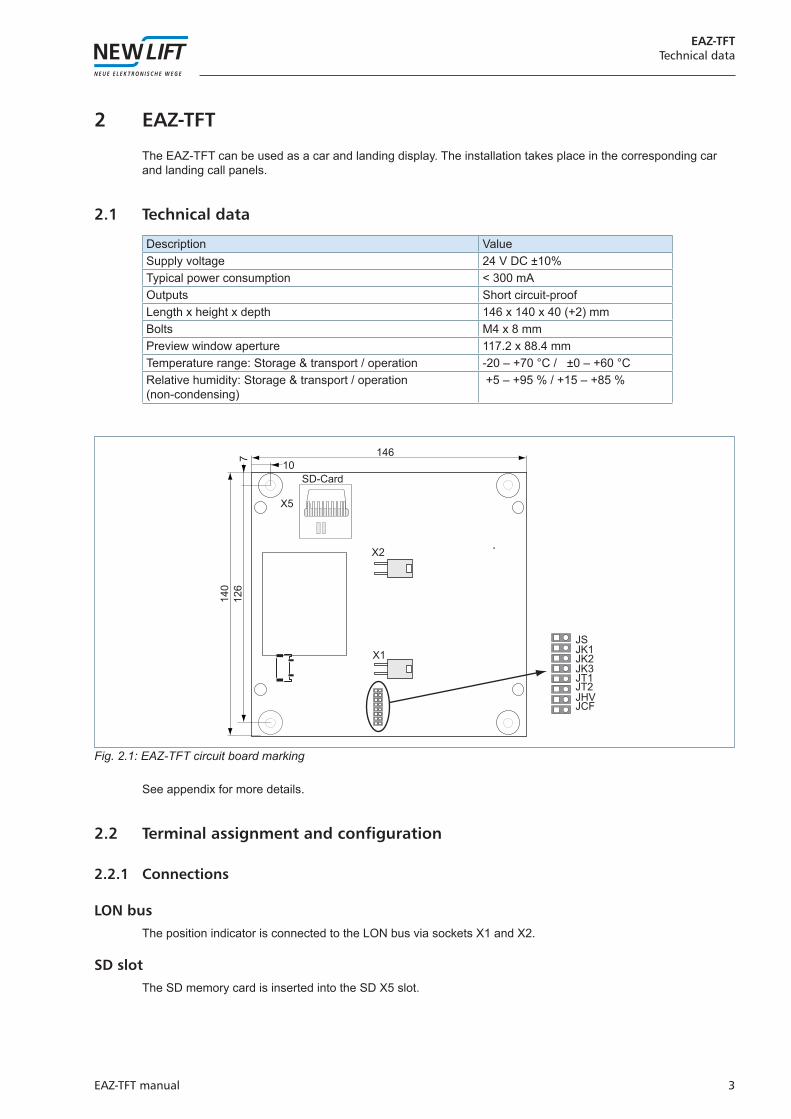
2.1 Technical data
Description ValueSupply voltage 24 V DC ±10%Typical power consumption < 300 mAOutputs Short circuit-proofLength x height x depth 146 x 140 x 40 (+2) mmBolts M4 x 8 mmPreview window aperture 117.2 x 88.4 mmTemperature range: Storage & transport / operation -20 – +70 °C / ±0 – +60 °CRelative humidity: Storage & transport / operation (non-condensing)
+5 – +95 % / +15 – +85 %
JSX1
X2
X5
SD-Card
JK1JK2JK3JT1JT2JHVJCF
140
126
14610
7
Fig. 2.1: EAZ-TFT circuit board marking
See appendix for more details.
2.2 Terminal assignment and configuration
2.2.1 Connections
LON busThe position indicator is connected to the LON bus via sockets X1 and X2.
SD slotThe SD memory card is inserted into the SD X5 slot.

EAZ-TFTTerminalassignmentandconfiguration
4 EAZ-TFTmanual
2.2.2 Jumpers
The service jumper JS is not plugged in.
Jumper J1 – J3: FST assignment
FST assignment JK1 JK2 JK3FST A open open openFST B plugged open openFST C open plugged openFST D plugged plugged openFST E open open pluggedFST F plugged open pluggedFST G open plugged pluggedFST H plugged plugged plugged
Jumper JT1: Door side
Installation position TIDoor side A openDoor side B plugged
Jumper JT2No function yet.
Jumper JVH: Installation position
Installation position VHHorizontal openVertical (currently not supported)
plugged
Jumper JCF: Installation site
Installation site CFLanding openCar plugged
2.2.3 Configurations via the FST control system
The EAZ-TFT must be selected as the EAZ type before you can make settings via the FST
Setting the EAZ type ► Config / EAZ Configuration / LON-EAZ Type ► Set EAZ-TFT with £ ¢ and confirm with E ► Exit menu and save settings with ¥.
In addition to the jumper settings, the following settings can be made via the FST menu Config->EAZ Configuration->LON-EAZ Config:
› Design selection: NEW LIFT provides 16 standard factory designs (0000 dddd) › Languages: German, English
Setting design and language ► Config / EAZ Configuration / LON-EAZ Config ► Select the individual digits with ¥ ¤ and set the respective digit with £ ¢ and confirm with E ► Exit menu and save settings with ¥.

EAZ-TFTUploadingthesoftwareupdate
EAZ-TFTmanual 5
The settings are made according to the following bit pattern. The designs (for an overview, see „Fig. 2.2: Over-view of standard designs with associated bit patterns“
Fig. 2.2: Overview of standard designs with associated bit patterns
S 0 0 0 D D D D11 22 44 88
Bit 0 - 3: Standard DesignsBit 7: Sprachauswahl: 0 = Deutsch; 1 = Englisch
Fig. 2.3: Bit pattern for settings of the EAZ-TFT in the FST menu
2.3 Uploading the software update ► Unzip the Update_Vxxx.zip file and copy the directory update to the existing SD card.
There must be at least one EAZ design on the SD card!!
► Reinsert the SD card into the EAZ-TFT and restart the EAZ-TFT.The update will run after the boot screen. It takes about 1-5 minutes. Do not switch off the EAZ during this time.
The EAZ automatically restarts following the successful update. The software version is then updated in the boot screen.
EAZDesignerRequirements
6 EAZ-TFTmanual
3 EAZDesigner
NEW LIFT has developed the user-friendly EAZ Designer specifically for the EAZ-TFT. With its graphical Win-dows interface, the EAZDesigner enables the simple, customised design of the EAZ-TFT.
3.1 Requirements
PC operating system XP, Vista or Windows 7 Microsoft .NET Framework 3.5 or higher PC equipment Internal or external SD card reader
3.2 Installation
Simply follow the instructions of the installation manager. If you have not yet installed Microsoft .NET Frame-work on your PC, the latest version of .NET should automatically begin to download.
3.3 Work areas
3.3.1 Menu bar › New: Opens new project › Open: Opens the project folder of the EAZDesigner. This is how to open existing projects. › Save as: Opens the window to save the current project › Save: Saves the current project › Create display output: Opens the window to select the SD card as the storage medium for a finished project › Format SD card: Formats the SD card › Language: Language selection
3.3.2 Preview area
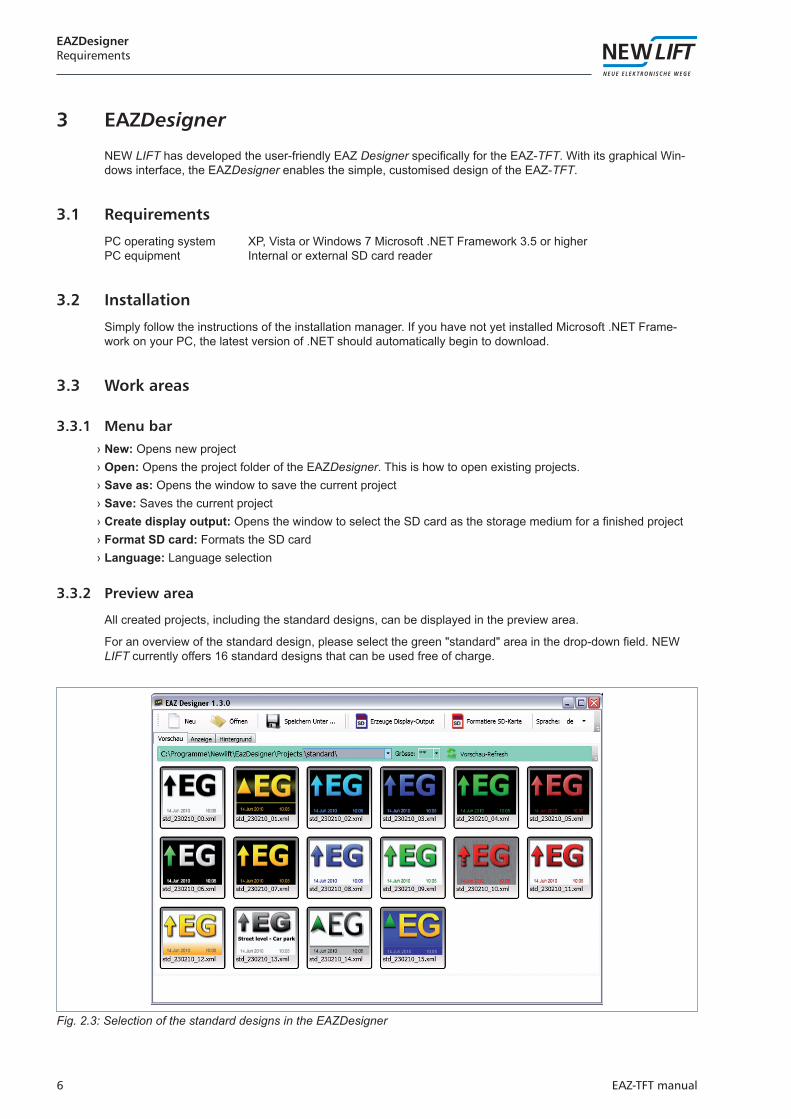
All created projects, including the standard designs, can be displayed in the preview area.
For an overview of the standard design, please select the green "standard" area in the drop-down field. NEW LIFT currently offers 16 standard designs that can be used free of charge.
Fig. 2.3: Selection of the standard designs in the EAZDesigner
EAZDesignerWorkareas
EAZ-TFTmanual 7
Opening an existing design ► Select the design and click the open button. ► The program automatically switches to the display area.
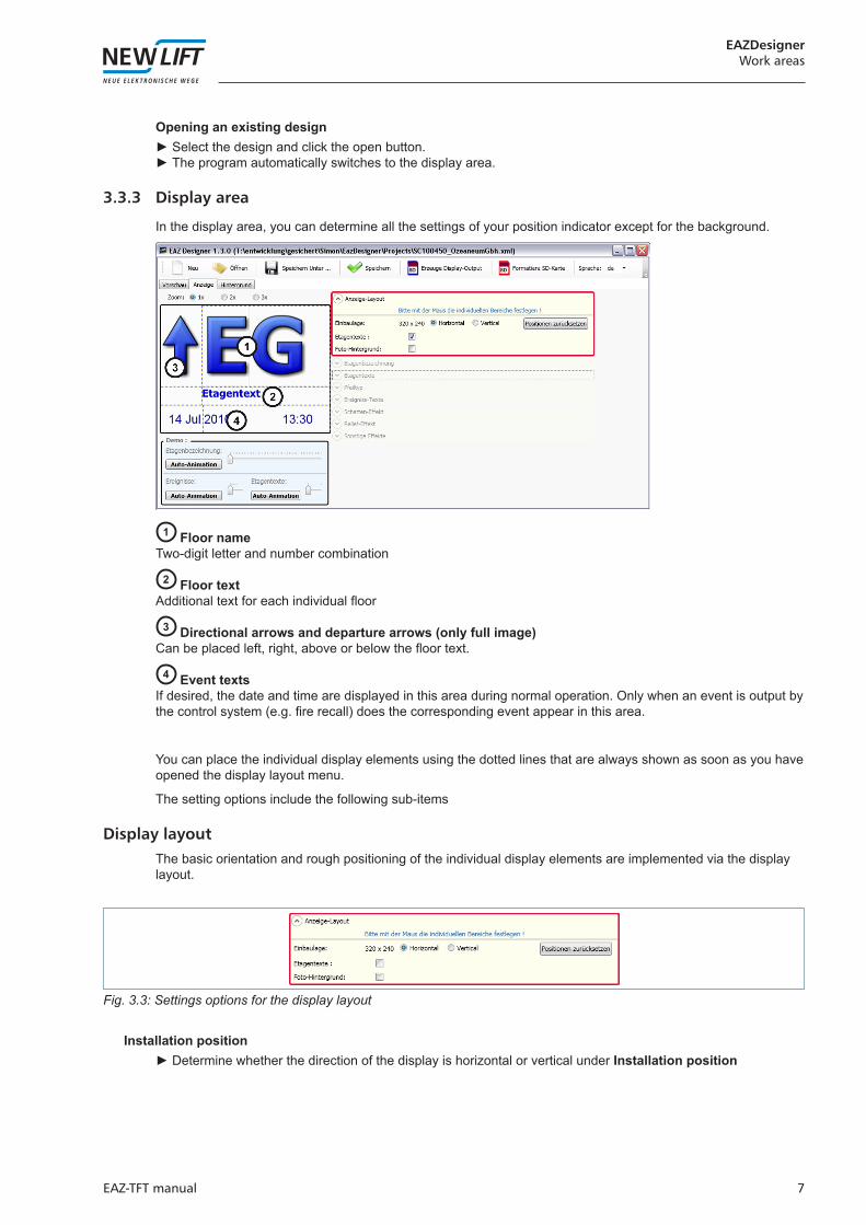
3.3.3 Display area
In the display area, you can determine all the settings of your position indicator except for the background.
1 Floor nameTwo-digit letter and number combination
2 Floor textAdditional text for each individual floor
3 Directional arrows and departure arrows (only full image)Can be placed left, right, above or below the floor text.
4 Event textsIf desired, the date and time are displayed in this area during normal operation. Only when an event is output by the control system (e.g. fire recall) does the corresponding event appear in this area.
You can place the individual display elements using the dotted lines that are always shown as soon as you have opened the display layout menu.
The setting options include the following sub-items
Display layoutThe basic orientation and rough positioning of the individual display elements are implemented via the display layout.
Fig. 3.3: Settings options for the display layout
Installation position ► Determine whether the direction of the display is horizontal or vertical under Installation position

EAZDesignerWorkareas
8 EAZ-TFTmanual
Floor text
In addition to the floor names (G, B, 1st, etc.), individual floor texts can be added to the floors (lobby, parking garage, ladies department, etc.). The floor text appears below the floor name. It is associated with the floor and must therefore be entered for each floor.
► Activate the Floor text checkbox ª The list of setting options now also shows the item "Floor text"
Background image
All common image files (JPG, TIFF, PNG) can be used as a background. If it is a picture or other graphic, the shadowing and 3D effects are omitted from the floor names and arrows.
► Activate the Photo background checkbox
If it is a logo that is placed on a solid-coloured background next to the display elements, all functions are availa-ble and the photo background checkbox does not have to be activated.
Positioning the display elements
The position and size of the individual elements can be changed by using the mouse on the dotted lines. This is how to make the first rough settings. Fine adjustments can be made later via the corresponding setting points.
Floor nameFloor names are adopted from the FST by default. Optical adjustments can be made here as follows.
Fig. 3.3: Setting options for floor names
Positioning the floor name
The position of the floor name depends on the selected alignment (align left, centre, right) and the borders (left, top, right)
► Orientation: In the drop-down menu, select between align left, centre and right to align the floor name ► Borders: Change the values left, top, right to finely adjust the positioning of the floor name
Fixed digit width
Because digits have different tracking depending on the font, this can lead to an uneven number continuation when running through the floors. A fixed width can be set for all digits in order to avoid this.
► Activate the fixed digit width checkbox
Fonts
A number of fonts are available in the drop-down menu. Depending on the font family, additional font styles can be selected (regular, bold, extra bold)

EAZDesignerWorkareas
EAZ-TFTmanual 9
Colour settings
The characters can also be customised by borders or colour filling. You can choose between various widths, colours and effects.
Floor texts (if under floor text display layout)Floor texts are texts that are displayed in addition to the floor name (e.g. lobby, parking garage, ladies depart-ment, etc.). These texts must be entered individually for each floor.
If the floor text field is not visible, activate the floor text checkbox in the display layout field
Fig. 3.3: Setting options for floor texts
Creating floor texts ► Use the + and - floor buttons to set the desired floor number ► Complete the floor text for the respective floor in the floor text field (line breaks are added with ; ) ► If desired, change the font, style, size, colour and border
To check the settings, either click on the respective floor text or on the Auto animation floor text button in the demo window below the display.
Forced floor name
You can replace or supplement the default floor names output by the FST using a forced floor name that you have defined.
► Activate the Short description instead of FST text checkbox ► Enter a short description (up to 5 digits) to replace the text output by the FST or enter a 2-digit text and ** (placeholder for FST text) to supplement the FST text (e.g. **FL: Output of the floors as 1st FL, 2nd FL, etc.)
Numbering: The lowest floor corresponds to floor 0.

EAZDesignerWorkareas
10 EAZ-TFTmanual
Arrow styleThe form and colour of all arrow types can be customised independently of each other.
Fig. 3.3: Setting options for arrow styles
Arrow type ► Activate the Editable down arrow checkbox if you want to design the up and down arrows differently ► Click on the desired arrow to set its position, form and colour settings
Position ► Select an arrow position from the drop-down menu (left, top, bottom, right)
Fillings & borders ► Use the Filling method drop-down menu to determine whether the arrow is to be displayed proportionally or to fit the area ► Make the fine adjustments to the borders in the numeric fields
Colour settings
The characters can also be customised by borders or colour filling. You can choose between various widths, colours and effects.
Event textsFor events, the EAZDesigner provides a list with preset event texts (all can be changed and expanded). If none of the events are active, the date and time output by the FST can be displayed if desired.
Additional informational text can be displayed with each event text. Here the event and informational text are displayed alternately. The informational text can also be used as a translation in order to alternately display German / English.

EAZDesignerWorkareas
EAZ-TFTmanual 11
Fig. 3.6: Setting options for event texts
Event texts ► Customise the event texts via the Text1;Info1 and Text2;Info2 fields ► Customise the font and background colour as well as the font family and style using the text settings ► Position the floor text using the position/length bar
Informational texts ► Add the desired informational text directly after the event text and separate them with a ;Example: Emergency stop;Please remain calm ► Activate the Flashing text function so that the text and information are displayed alternately
To check the settings, either click on the respective event or on the Auto-Animation events button in the demo window below the display. The cursor in the Preview partial text indicates which of the event columns (Text1, Info1, Text2 or Info2) is currently being displayed in the preview
Date & time
Under Date/time you can choose whether you want to display this information during normal operation ► From the drop-down field, choose the format for the date and ► make fine adjustments to the position using the fields date left, date at top, time left, time at top ► If desired, change the spelling of the name of the month (remember that you may have to reduce the font size)
Graphics
Corresponding symbols can be displayed in addition to the event notifications. NEW LIFT offers a graphics lib-rary to be used free of charge. However, you can also embed custom symbols in png format. The graphics can be displayed as a small icon next to the text or as a full image above the event text.
► Activate the Use symbol checkbox and select a graphic using the ... button ► With the Full image checkbox, determine whether the symbol is to be placed as a small icon next to the event text or as a full image above the event text ► With the Shadow checkbox, determine whether the symbol should have a shadow effect ► Set the desired size using the Size bar and position the graphic using the Position bar

EAZDesignerWorkareas
12 EAZ-TFTmanual
Shadow effectTo give the display elements a 3-dimensional appearance, you can add shadowing. Here you can change the shadow width, softness, angle, colour and random noise. All settings can also be reset using the set Shadow standards button.
Fig. 3.7: Setting options for shadow effect
Relief effectThe so-called relief effect can provide floor names and arrows with different reliefs. You can decide between the various widths and natures of the effect.
Fig. 3.8: Setting options for floor name
Other EffectsUsing this window you can increase the random noise of the display or darken it.
Fig. 3.9: Setting options for other effects
Demo window › You will see a window with several auto-animation buttons below the preview. Here you can view floor names, floor texts and events as auto-animations.

EAZDesignerGettingstarted
EAZ-TFTmanual 13
3.3.4 Background area
Fig. 3.10: Setting options for the background
Here you can make all of the settings for the background of your position indicator.
If you would like a background image for your position indicator, you can upload this into the program using the Upload image button.
You can, of course, use background colours and gradients instead of a background image.
3.4 Getting started
Here are some procedural tips if you would like to create your personal position indicator. › First choose a background (e.g. file with your company logo) in order to be sure that you can later place the display elements accordingly.
› Now open the display layout field and leave this open during the entire design process. You can change the position of the individual elements at any time by using the dotted lines.
› In the display layout field, choose whether you would like to display extended floor texts and determine whether you are using a plain background or a photo/other image file.
› Open the arrow layout field and make sure that the 'editable down arrow' checkbox is deactivated (an activated checkbox is only necessary if you want different up and down arrows. If this is the case, please only activate the checkbox after completing the editing and then make the individual settings for the down or departure arrow). Now determine whether the arrows are to be placed to the left, right, top, or bottom of the floor text
› Finally, you can move the dotted lines using the drag and drop function and can thus change the position of the display elements. Tip: If you want to set the arrows above or below the floor texts or want to display extended floor texts, you must first move the dotted lines before these settings will be visible
› If you have roughly determined the position of the display elements, you can still make fine adjustments to the position, colour, fonts, etc. in the respective field.

NEWLIFTSteuerungsbauGmbH
LochhamerSchlag882166Gräfelfing
Phone+49 89 – 898 66 – 0Fax +49 89 – 898 66 – 300Mail [email protected]
ServicelinePhone+49 89 – 898 66 – 110Mail [email protected]
www.newlift.de
14
0,0
mm
12
6,0
mm
88
,4m
m
44
,2m
m4
4,2
mm
146,0mm
126,0mm
117,2mm
58,6mm 58,6mm
4x 5,0mm�
4x Kunststoff Abstandsbolzen mit beidseitigemM4 Innengewinde und 23,0mm Länge2
,0
m
m
23
,0m
m
42
,0m
m±0,1
Alle Toleranzen 0,2mm sofern nicht anders angegeben!±