Embed Size (px)
Citation preview
Position Monitored Active CartridgesSeries RSE/SI1DIN 24342 or ISO 7368 Size 16 to 100
RSE_Cover 8/8/03 4:10 PM Seite 2
3
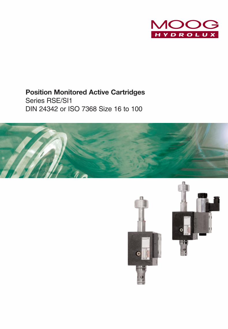
Table of Contents
BG - Approval Certificate 18
Notes 19
Ordering Information 16
Spare Parts 17
Standard Models 9
Dimensions 11
Technical Dates of the Position Switch 7
Typical Characteristic Curves 8
Different Types 5
Specifications and Characteristic Parameters 6
Description Page
General Description of Layout and Function 4
4
General Description of Layout and Function
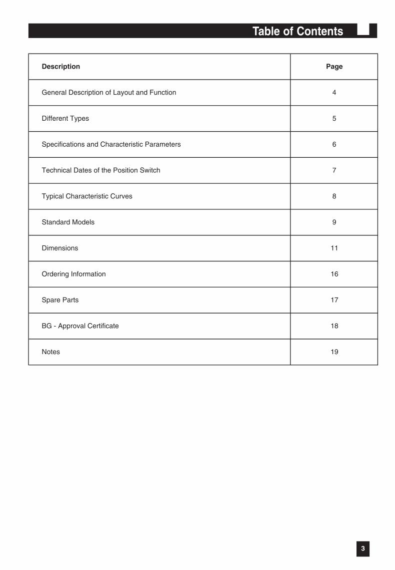
Position monitored active cartridge formanifold mounting
Ports A and B are either closed or fully openallowing bi-directional flow.
Valve description:
The valve comprises a sleeve (2), seated poppet(1) with integral tail rod (4), a non contactingposition monitoring switch (5) and the valve body(3).The seated poppet (1) can be controlled by anintegral pilot valve (6) mounted on the valve bodyor externally pilot through the interface ports X andY. Fast opening and closing times are achieved viathe active pilot areas AX and AY. The positionmonitoring switch (5) is operated when the nose(7) of the poppet (1) enters the seat diameter onthe sleeve (2) closing ports A and B. The poppet(1) then contacts the seat (9) fully blocking ports Aand B.
Advantages:
ÿ No dynamic sealing for position monitoringswitch.
ÿ Direct monitoring of the closed position.ÿ High cycle life.ÿ Zero leakage due to seals (8) and metal to
metal seat (9) – (excluding pilot valveleakage).
Application examples:
ÿ Presses.ÿ Injection moulding machines.ÿ Lifting equipment.ÿ Any application requiring position
monitored cartridges.
BG Approval certificate (see page 18):
ÿ All valves up to NG100.ÿ Approval includes the NG06 adaptor plate
for the WX3 version.ÿ For the WX1 and WX2 versions the
approval is for the main valve only.
Warning: The approval applies to valvestested, set and sealed at MoogHydrolux.
It is essential this setting is notmodified or tampered with, ifthis should happen then the BGapproval would be void.
5
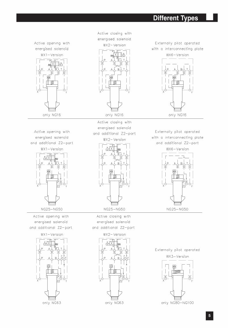
Different Types
6
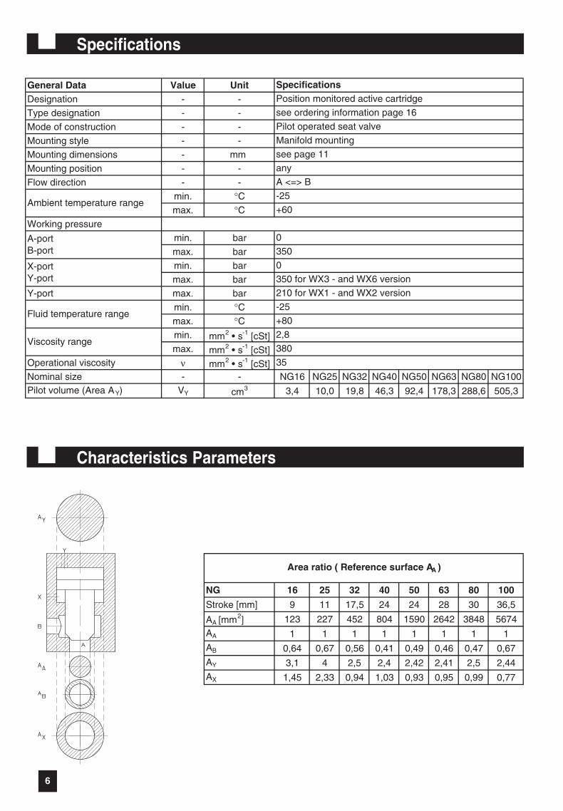
Specifications
Characteristics Parameters
General Data Value UnitDesignation - -
Type designation - -
Mode of construction - -
Mounting style - -
Mounting dimensions - mm
Mounting position - -
Flow direction - -
min. °Cmax. °C
Working pressure
min. bar
max. bar
min. bar
max. bar
Y-port max. bar
min. °Cmax. °Cmin. mm2 • s-1 [cSt]max. mm2 • s-1 [cSt]
Operational viscosity ν mm2 • s-1 [cSt]Nominal size - - NG16 NG25 NG32 NG40 NG50 NG63 NG80 NG100Pilot volume (Area AY) VY cm3 3,4 10,0 19,8 46,3 92,4 178,3 288,6 505,3
35
380
2,8
+60
-25
A <=> B
any
Viscosity range
Specifications
Ambient temperature range
Position monitored active cartridge
see ordering information page 16
Pilot operated seat valve
see page 11
Manifold mounting
0
Fluid temperature range
210 for WX1 - and WX2 version
-25
350A-portB-port
X-portY-port
+80
0
350 for WX3 - and WX6 version
NG 16 25 32 40 50 63 80 100
Stroke [mm] 9 11 17,5 24 24 28 30 36,5
AA [mm2] 123 227 452 804 1590 2642 3848 5674
AA 1 1 1 1 1 1 1 1
AB 0,64 0,67 0,56 0,41 0,49 0,46 0,47 0,67
AY 3,1 4 2,5 2,4 2,42 2,41 2,5 2,44
AX 1,45 2,33 0,94 1,03 0,93 0,95 0,99 0,77
Area ratio ( Reference surface AA )
7
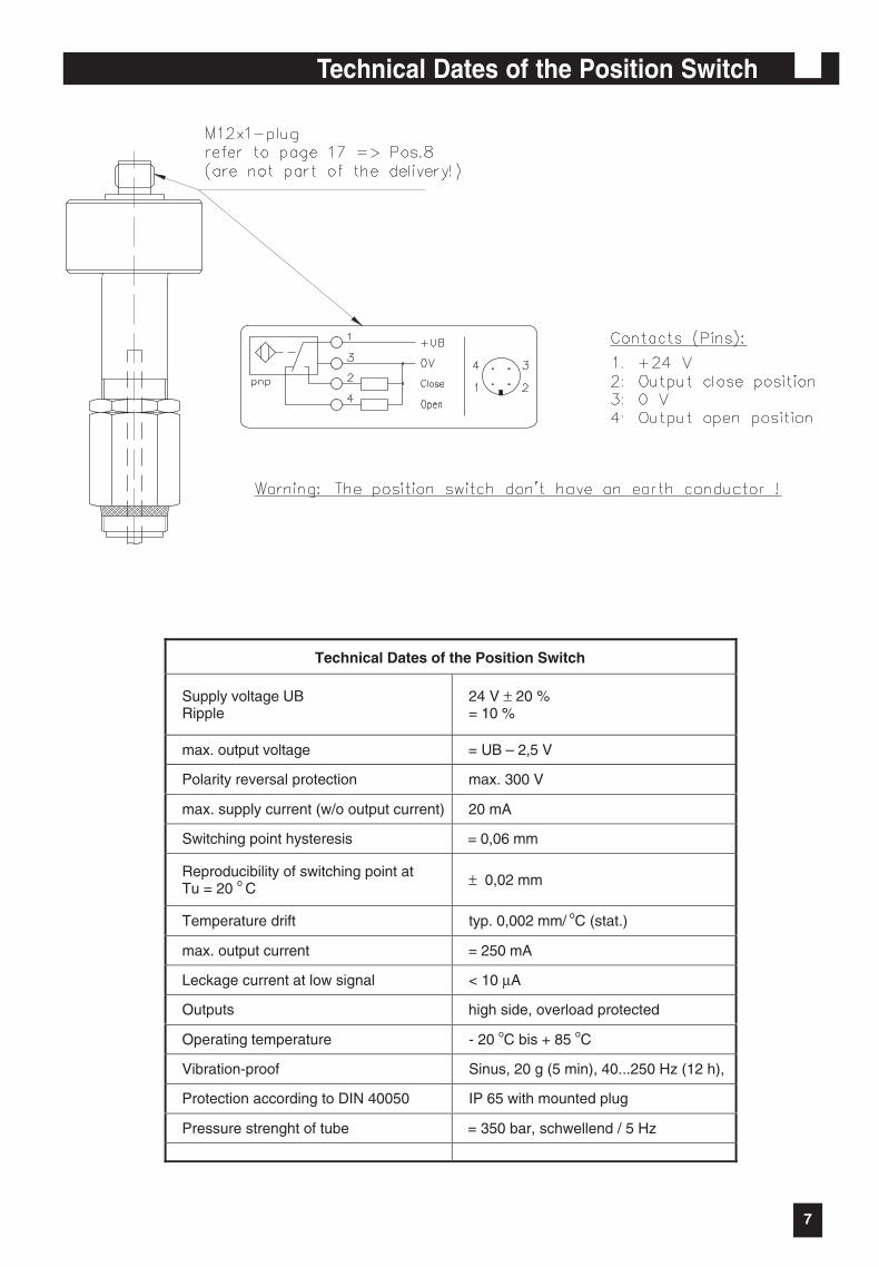
Technical Dates of the Position Switch
Technical Dates of the Position Switch
Supply voltage UBRipple
24 V ± 20 %= 10 %
max. output voltage = UB – 2,5 V
Polarity reversal protection max. 300 V
max. supply current (w/o output current) 20 mA
Switching point hysteresis = 0,06 mm
Reproducibility of switching point atTu = 20 o C ± 0,02 mm
Temperature drift typ. 0,002 mm/ oC (stat.)
max. output current = 250 mA
Leckage current at low signal < 10 µA
Outputs high side, overload protected
Operating temperature - 20 oC bis + 85 oC
Vibration-proof Sinus, 20 g (5 min), 40...250 Hz (12 h),
Protection according to DIN 40050 IP 65 with mounted plug
Pressure strenght of tube = 350 bar, schwellend / 5 Hz
8
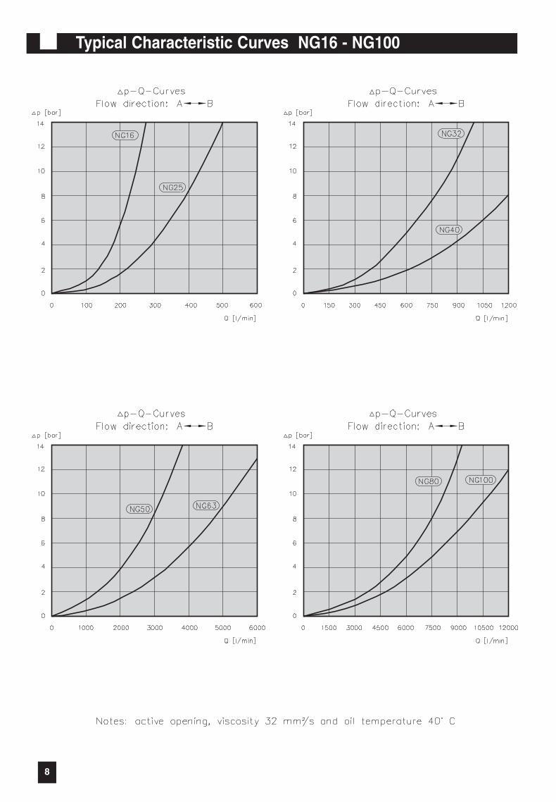
Typical Characteristic Curves NG16 - NG100
9
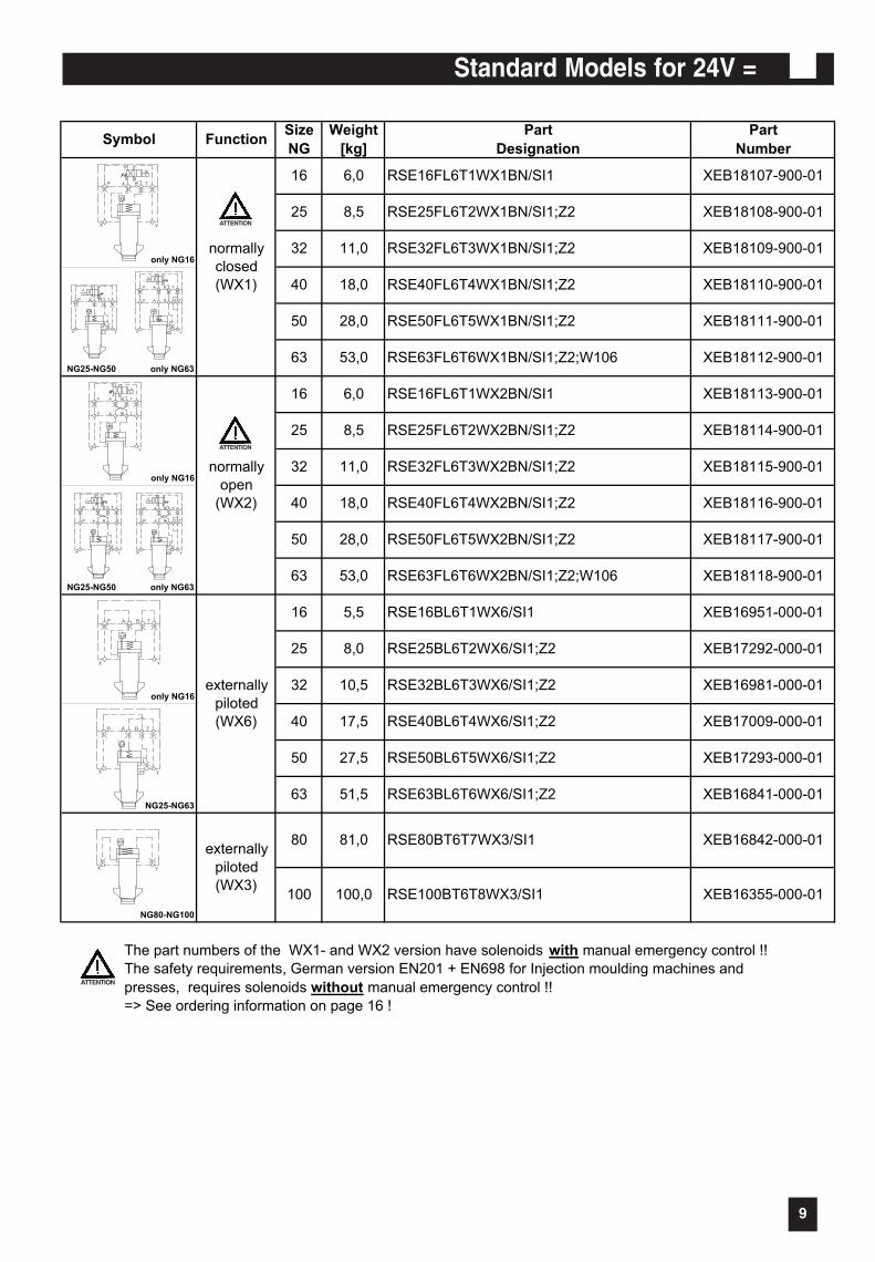
Standard Models for 24V =
RSE 8/8/03 2:58 PM Seite 9
XEB17009-000-01
XEB17293-000-01
XEB16841-000-01
XEB16842-000-01
XEB18118-900-01
XEB16951-000-01
XEB17292-000-01
XEB16981-000-01
XEB18114-900-01
XEB18115-900-01
XEB18116-900-01
XEB18117-900-01
RSE40BL6T4WX6/SI1;Z2
RSE50BL6T5WX6/SI1;Z2
RSE63BL6T6WX6/SI1;Z2
XEB18107-900-01
XEB18108-900-01
XEB18109-900-01
XEB18110-900-01
XEB18111-900-01
XEB18112-900-01
XEB18113-900-01
RSE32FL6T3WX2BN/SI1;Z2
RSE25FL6T2WX2BN/SI1;Z2
RSE100BT6T8WX3/SI1
RSE80BT6T7WX3/SI1
RSE50FL6T5WX2BN/SI1;Z2
RSE40FL6T4WX2BN/SI1;Z2
RSE63FL6T6WX2BN/SI1;Z2;W106
RSE16BL6T1WX6/SI1
RSE25BL6T2WX6/SI1;Z2
RSE32BL6T3WX6/SI1;Z2
RSE50FL6T5WX1BN/SI1;Z2
RSE63FL6T6WX1BN/SI1;Z2;W106
RSE16FL6T1WX2BN/SI1
RSE16FL6T1WX1BN/SI1
RSE25FL6T2WX1BN/SI1;Z2
RSE32FL6T3WX1BN/SI1;Z2
RSE40FL6T4WX1BN/SI1;Z2
11,0
18,0
28,0
53,0
28,0
53,0
6,0
8,5
6,0
8,5
11,0
18,0
32
40
50
63
50
63
16
25
16
25
32
40
Part
Designation
Part
NumberSymbol
Weight
[kg]
Size
NGFunction
normally
open
(WX2)
normally
closed
(WX1)
only NG16
NG25-NG50 only NG63
only NG16
NG25-NG50 only NG63
only NG16
25 8,0
32 10,5
NG25-NG63
40 17,5
50 27,5
63 51,5
externally
piloted
(WX6)
16 5,5
The part numbers of the WX1- and WX2 version have solenoids with manual emergency control !!
The safety requirements, German version EN201 + EN698 for Injection moulding machines and
presses, requires solenoids without manual emergency control !!
=> See ordering information on page 16 !
81,0
100,0
externally
piloted
(WX3)
NG80-NG100
80
100 XEB16355-000-01
ATTENTION
ATTENTION
ATTENTION
10
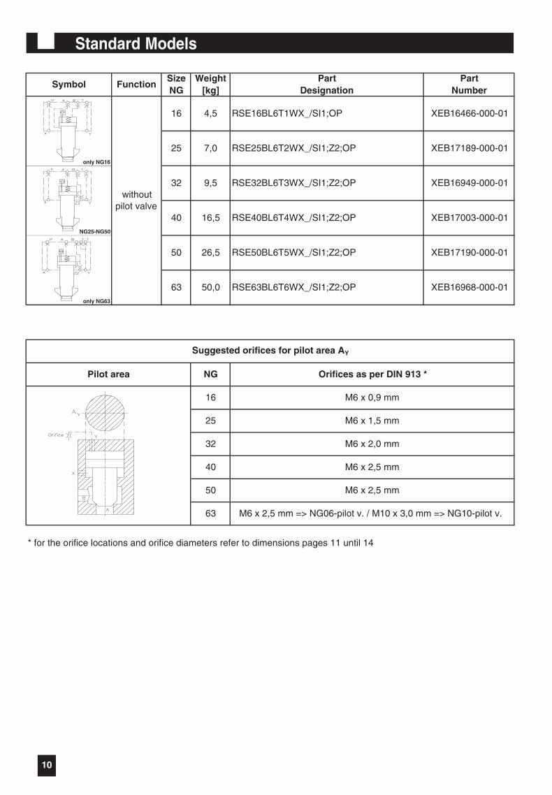
Standard Models
M6 x 2,5 mm
Pilot area NG Orifices as per DIN 913 *
withoutpilot valve
M6 x 0,9 mm
M6 x 1,5 mm
M6 x 2,0 mm
RSE16BL6T1WX_/SI1;OP
16
32
25
40
50
63
M6 x 2,5 mm
M6 x 2,5 mm => NG06-pilot v. / M10 x 3,0 mm => NG10-pilot v.
RSE50BL6T5WX_/SI1;Z2;OP
Suggested orifices for pilot area AY
PartDesignation
PartNumber
SymbolWeight
[kg]SizeNG
Function
XEB17190-000-01
XEB16968-000-01
32
40
RSE63BL6T6WX_/SI1;Z2;OP
XEB16466-000-01
XEB17189-000-01
XEB16949-000-01
XEB17003-000-01
RSE25BL6T2WX_/SI1;Z2;OP
RSE32BL6T3WX_/SI1;Z2;OP
RSE40BL6T4WX_/SI1;Z2;OP
4,5
7,0
9,5
16,5
* for the orifice locations and orifice diameters refer to dimensions pages 11 until 14
only NG16
NG25-NG50
only NG63
50
63
26,5
50,0
16
25
11
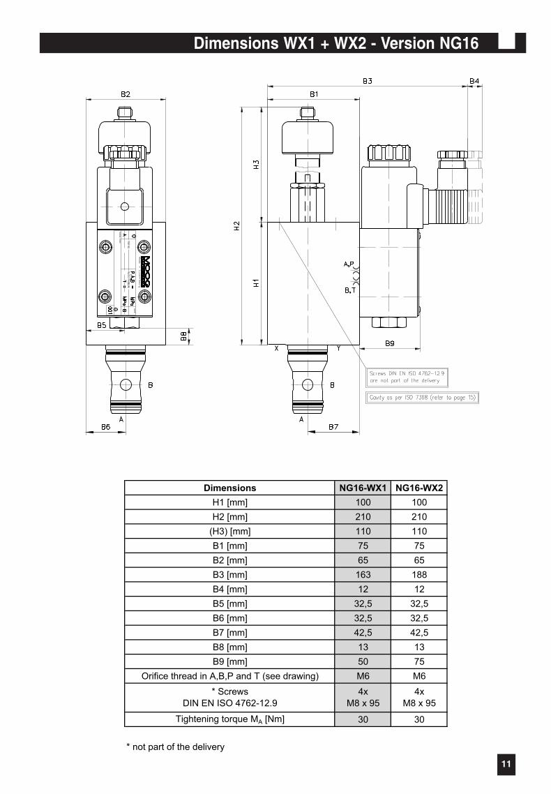
Dimensions WX1 + WX2 - Version NG16
Dimensions NG16-WX1 NG16-WX2
H1 [mm] 100 100
H2 [mm] 210 210
(H3) [mm] 110 110
B1 [mm] 75 75
B2 [mm] 65 65
B3 [mm] 163 188
B4 [mm] 12 12
B5 [mm] 32,5 32,5
B6 [mm] 32,5 32,5
B7 [mm] 42,5 42,5
B8 [mm] 13 13
B9 [mm] 50 75
Orifice thread in A,B,P and T (see drawing) M6 M6
Tightening torque MA [Nm] 30 30
* not part of the delivery
* Screws
DIN EN ISO 4762-12.9
4x
M8 x 95
4x
M8 x 95
12
Dimensions WX1 + WX2 -Versio NG 63
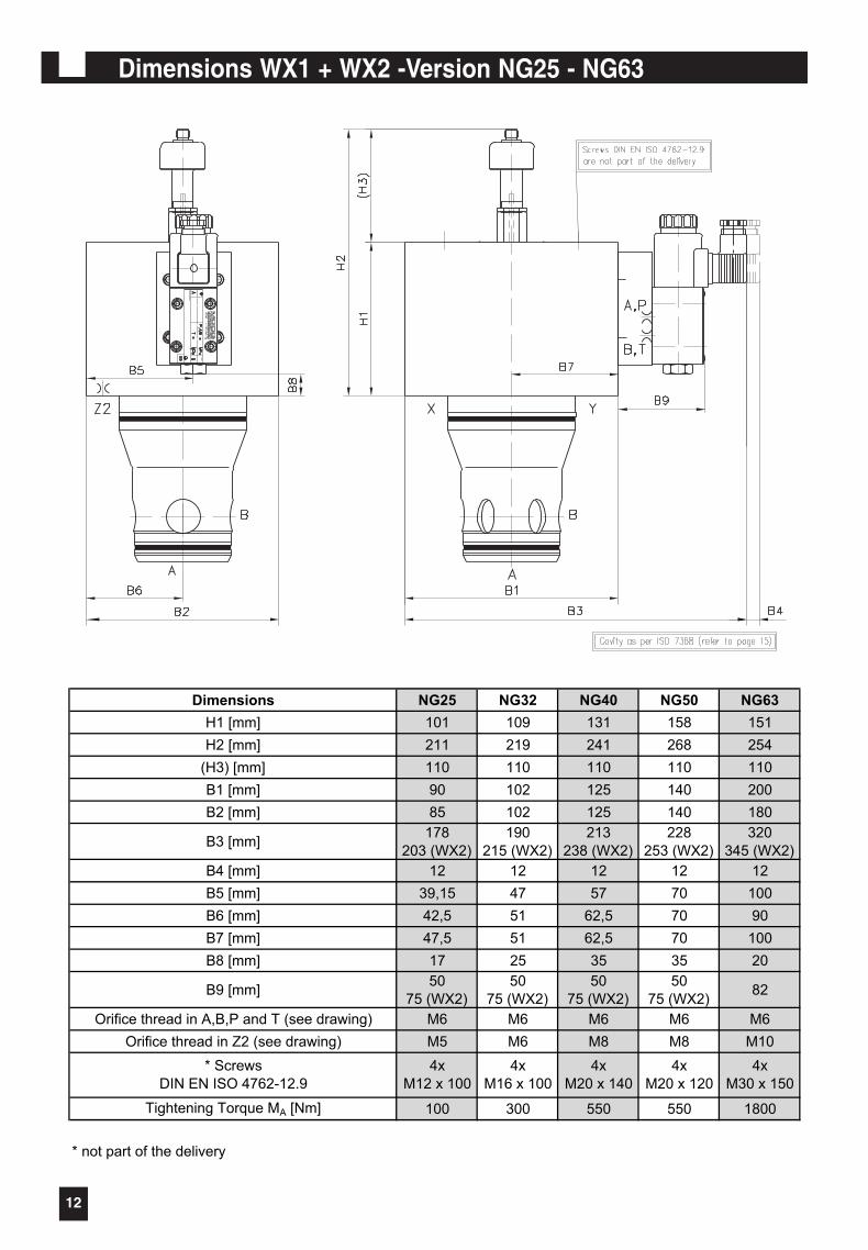
Dimensions NG25 NG32 NG40 NG50 NG63
H1 [mm] 101 109 131 158 151
H2 [mm] 211 219 241 268 254
(H3) [mm] 110 110 110 110 110
B1 [mm] 90 102 125 140 200
B2 [mm] 85 102 125 140 180
B3 [mm]178
203 (WX2)
190
215 (WX2)
213
238 (WX2)
228
253 (WX2)
320
345 (WX2)
B4 [mm] 12 12 12 12 12
B5 [mm] 39,15 47 57 70 100
B6 [mm] 42,5 51 62,5 70 90
B7 [mm] 47,5 51 62,5 70 100
B8 [mm] 17 25 35 35 20
B9 [mm]50
75 (WX2)
50
75 (WX2)
50
75 (WX2)
50
75 (WX2)82
Orifice thread in A,B,P and T (see drawing) M6 M6 M6 M6 M6
Orifice thread in Z2 (see drawing) M5 M6 M8 M8 M10
Tightening Torque MA [Nm] 100 300 550 550 1800
* not part of the delivery
* Screws
DIN EN ISO 4762-12.9
4x
M30 x 150
4x
M12 x 100
4x
M16 x 100
4x
M20 x 140
4x
M20 x 120
NGDimensions WX1 + WX2 -Version NG25 - NG63
13
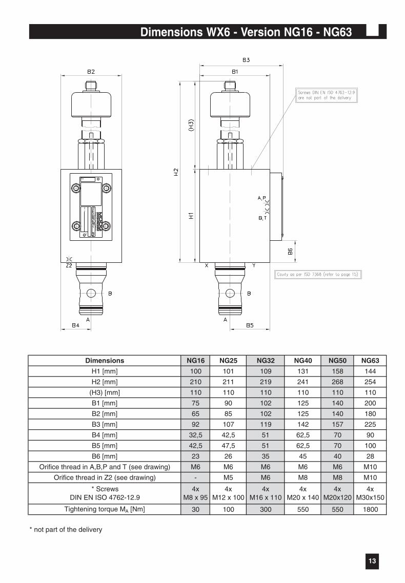
Dimensions WX6 - Version NG16 - NG63
Dimensions NG16 NG25 NG32 NG40 NG50 NG63
H1 [mm] 100 101 109 131 158 144
H2 [mm] 210 211 219 241 268 254
(H3) [mm] 110 110 110 110 110 110
B1 [mm] 75 90 102 125 140 200
B2 [mm] 65 85 102 125 140 180
B3 [mm] 92 107 119 142 157 225
B4 [mm] 32,5 42,5 51 62,5 70 90
B5 [mm] 42,5 47,5 51 62,5 70 100
B6 [mm] 23 26 35 45 40 28
Orifice thread in A,B,P and T (see drawing) M6 M6 M6 M6 M6 M10
Orifice thread in Z2 (see drawing) - M5 M6 M8 M8 M10
Tightening torque MA [Nm] 30 100 300 550 550 1800
* not part of the delivery
4xM30x150
4xM20 x 140
4xM20x120
* ScrewsDIN EN ISO 4762-12.9
4xM8 x 95
4xM12 x 100
4xM16 x 110
14
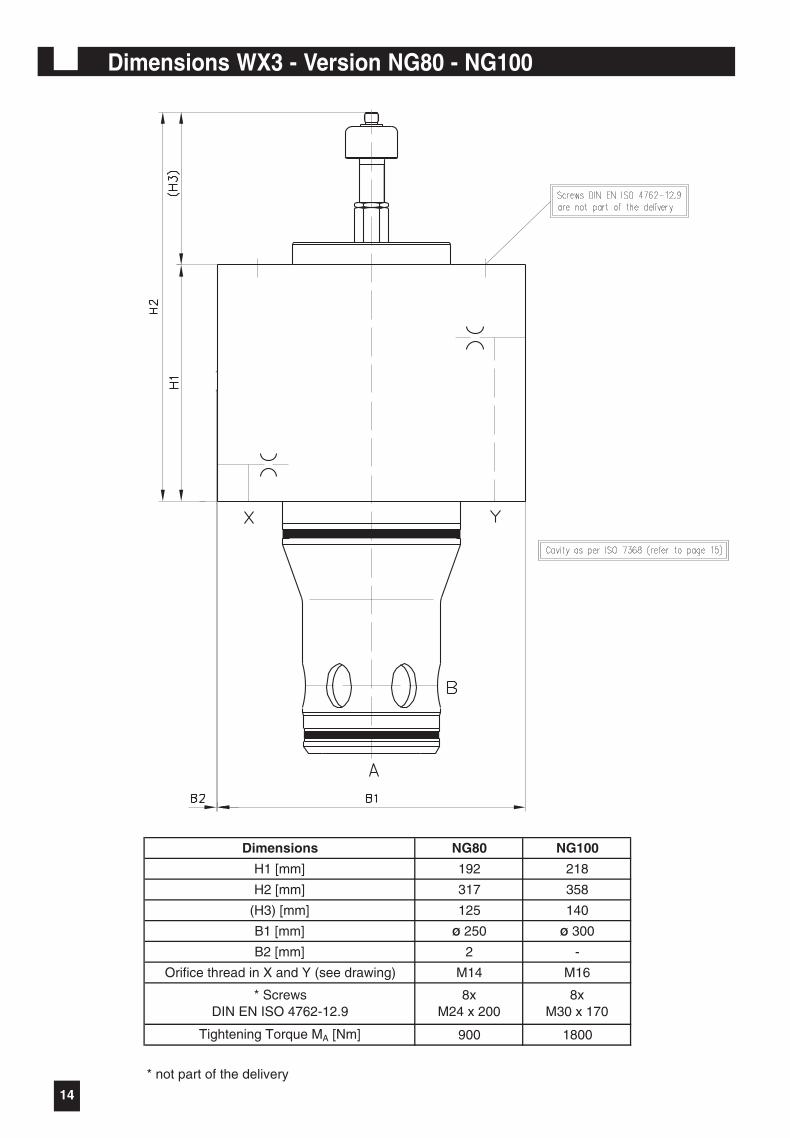
Dimensions WX3 - Version NG80 - NG100
Dimensions NG80 NG100
H1 [mm] 192 218
H2 [mm] 317 358
(H3) [mm] 125 140
B1 [mm] Ø 250 Ø 300
B2 [mm] 2 -
Orifice thread in X and Y (see drawing) M14 M16
Tightening Torque MA [Nm] 900 1800
* not part of the delivery
* ScrewsDIN EN ISO 4762-12.9
8xM24 x 200
8xM30 x 170
15
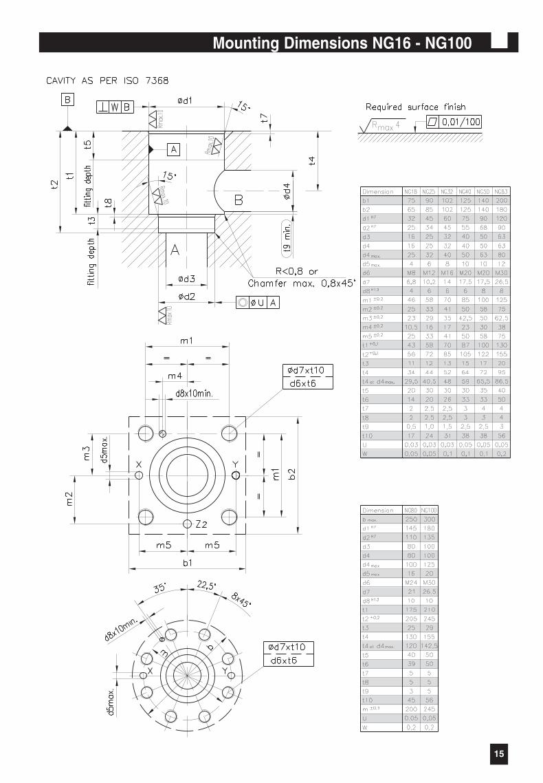
Mounting Dimensions NG16 - NG100
16
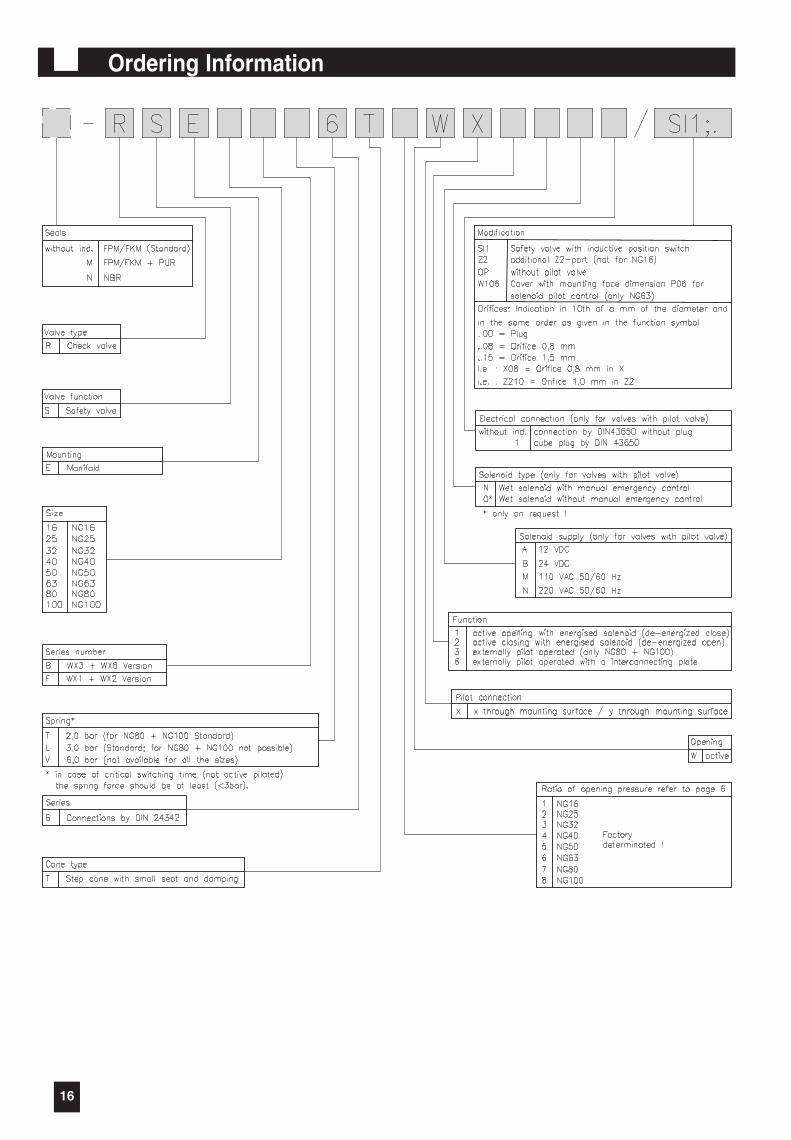
Ordering Information
RSE 8/11/03 7:29 AM Seite 16
17
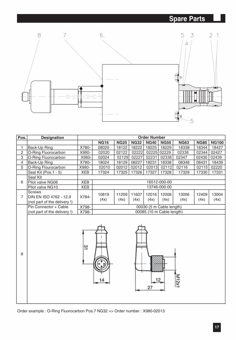
Spare Parts
Pos. DesignationNG16 NG25 NG32 NG40 NG50 NG63 NG80 NG100
1 Back-Up Ring X780- 08020 18122 18222 18225 18229 18338 18344 184272 O-Ring Fluorocarbon X980- 02020 02122 02222 02225 02229 02338 02344 024273 O-Ring Fluorocarbon X980- 02024 02129 02227 02231 02338 02347 02430 024394 Back-Up Ring X780- 18024 18129 08227 18231 18338 08348 08431 184395 O-Ring Flourocarbon X980- 02010 02012 02012 02013 02112 02116 02115 02220
Seal Kit (Pos.1 - 5) XEB 17324 17325 17326 17327 17328 17329 17330 17331Seal Kit Pilot valve NG06 XEBPilot valve NG10 XEB
X798-X798-
Order Number
Order example : O-Ring Fluorocarbon Pos.7 NG32 => Order number : X980-02013
11209(4x)
11607(4x)
12016(4x)
12409(4x)
12008(4x)
8
00085 (10 m Cable length)
7ScrewsDIN EN ISO 4762 - 12.9(not part of the delivery !)
X784-10819(4x)
6 16512-000-0013746-000-00
13006(4x)
13004(4x)
Pin Connector + Cable(not part of the delivery !)
00030 (5 m Cable length)
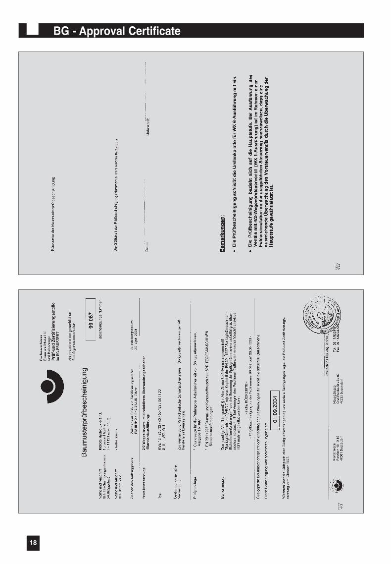
18
BG - Approval Certificate

19
Notes

AustraliaBrazilChina
DenmarkEnglandFinlandFrance
GermanyIndiaIrelandItaly
JapanKoreaLuxembourgPhilippinesSingaporeSpainSwedenUSA
MOOG HYDROLUX S.àr.l.1, rue de l’AciérieL-1112 LUXEMBOURGTel: (+352) 40 46 40-1Fax: (+352) 40 46 40-909E-mail: [email protected]
04/05 Rev1/X999-80226
RSE_Cover 8/8/03 4:10 PM Seite 1