Embed Size (px)
Citation preview
CDE/CDB3000Order Catalogue
Positioning and drive solutions
from 375 W to 90 kW (CDB3000)from 2 A to 170 A (CDE3000)
Cat
alog
ue -
Pos
ition
ing
Sys
tem
CD
E/C
DB
3000
Order Catalogue - CDE/CDB3000 Positioning Systems
ID no.: 1001.24B.5-00
Date: 10/2008
We reserve the right to make technical changes.
Cat
alog
ue -
Pos
ition
ing
Sys
tem
CD
E/C
DB
3000
The particular benefits to users of LTi drive control-lers lie in the expert solutions delivered for automa-tion with electric drives and in the high level of controlengineering know-how available to handle the controlof a wide range of motor types. Always keeping aneye on the physics, looking to make electric driveengineering the core element of machine optimisa-tion and automation.
It is a long-established fact in electric drives that thevarious control methods can complement each othereffectively in handling complex automation tasks.The best method of handling complex movementtasks depends in each case very heavily on the indi-vidual requirements of the user - and on the experi-ence and available equipment range of the supplier.Consequently, it is beneficial if all the options can beaccessed easily and without changing equipmentsetup, or even supplier.
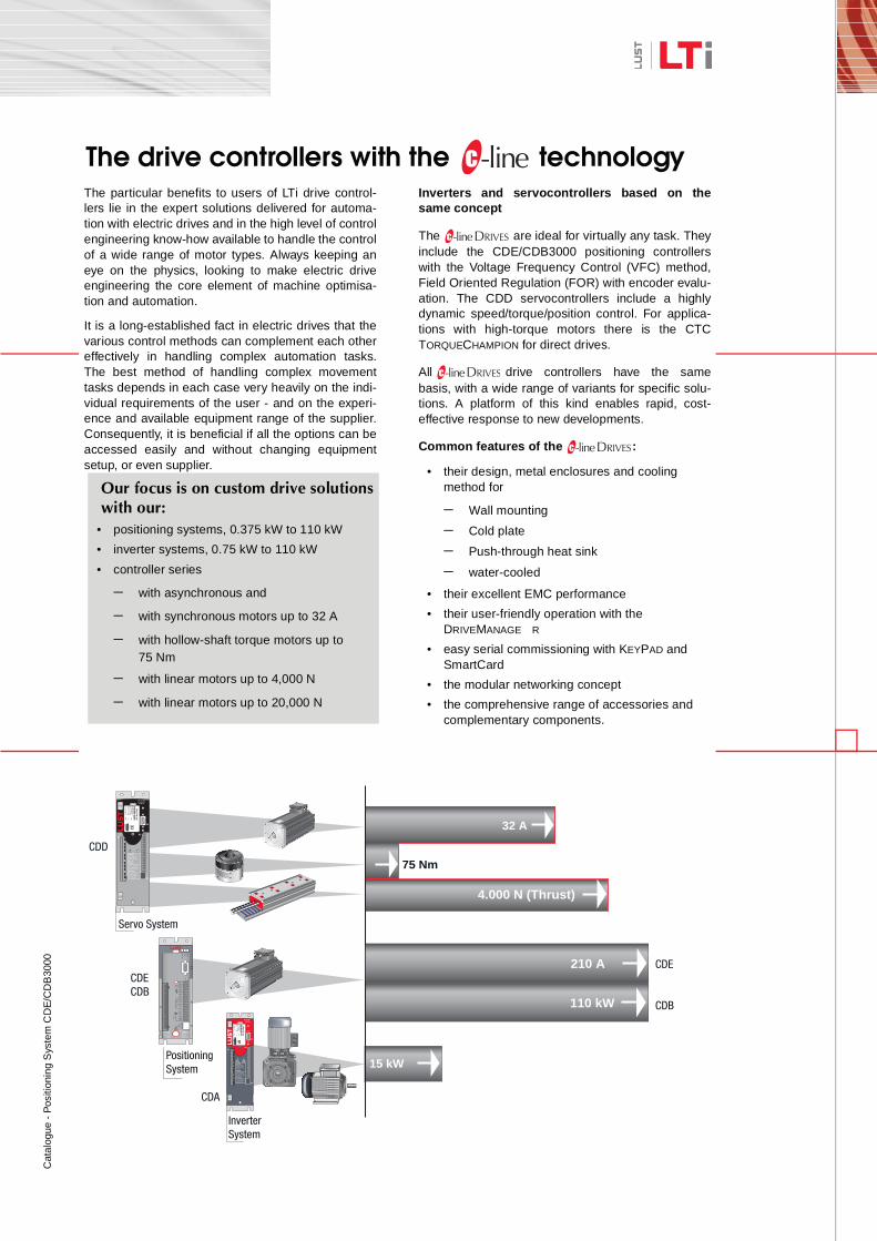
Inverters and servocontrollers based on thesame concept
The are ideal for virtually any task. Theyinclude the CDE/CDB3000 positioning controllerswith the Voltage Frequency Control (VFC) method,Field Oriented Regulation (FOR) with encoder evalu-ation. The CDD servocontrollers include a highlydynamic speed/torque/position control. For applica-tions with high-torque motors there is the CTCTORQUECHAMPION for direct drives.
All drive controllers have the samebasis, with a wide range of variants for specific solu-tions. A platform of this kind enables rapid, cost-effective response to new developments.
Common features of the :
• their design, metal enclosures and cooling method for
− Wall mounting
− Cold plate
− Push-through heat sink
− water-cooled
• their excellent EMC performance
• their user-friendly operation with the DRIVEMANAGE R
• easy serial commissioning with KEYPAD and SmartCard
• the modular networking concept
• the comprehensive range of accessories and complementary components.
The drive controllers with the technology
Our focus is on custom drive solutions with our:
• positioning systems, 0.375 kW to 110 kW
• inverter systems, 0.75 kW to 110 kW
• controller series
− with asynchronous and
− with synchronous motors up to 32 A
− with hollow-shaft torque motors up to 75 Nm
− with linear motors up to 4,000 N
− with linear motors up to 20,000 N
110 kW
PositioningSystem
LUST
15 kW
InverterSystem
LUST
Servo System
32 A
75 Nm
4.000 N (Thrust)
CDD
CDECDB
CDA
210 A CDE
CDB
Ca
talo
gue
- P
ositi
onin
g S
yste
m C
DE
/CD
B30
00
2
3
4
5
6
1
Ca
talo
gue
- P
ositi
onin
g S
yste
m C
DE
/CD
B30
00
2
3
4
5
1
6
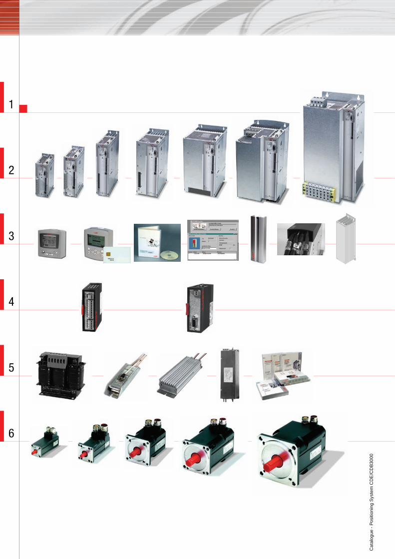
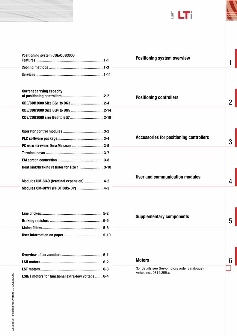
Positioning system overview
Current carrying capacity of positioning controllers ........................................... 2-2
CDE/CDB3000 Size BG1 to BG3 .................................. 2-4
CDE/CDB3000 Size BG4 to BG5 .................................. 2-14
CDE/CDB3000 size BG6 to BG7................................... 2-18
Operator control modules .......................................... 3-2
PLC software package................................................ 3-4
PC USER SOFTWARE DRIVEMANAGER ................................. 3-5
Terminal cover ............................................................ 3-7
EM screen connection ................................................ 3-8
Heat sink/braking resistor for size 1 ........................ 3-10
Modules UM-8I4O (terminal expansion) .................... 4-2
Modules CM-DPV1 (PROFIBUS-DP) ............................ 4-3
Line chokes................................................................ 5-2
Braking resistors ....................................................... 5-5
Mains filters ............................................................... 5-8
User information on paper ........................................ 5-10
Positioning controllers
Accessories for positioning controllers
User and communication modules
Supplementary components
Motors
(for details see Servomotors order catalogue) Article no.: 0814.25B.x
Overview of servomotors .......................................... 6-1
LSH motors................................................................. 6-2
LST motors ................................................................. 6-3
LSH/T motors for functional extra-low voltage........ 6-4
Positioning system CDE/CDB3000Features.......................................................................1-1
Cooling methods .........................................................1-3
Services.......................................................................1-11
Cat
alog
ue -
Pos
ition
ing
Sys
tem
CD
E/C
DB
3000
1
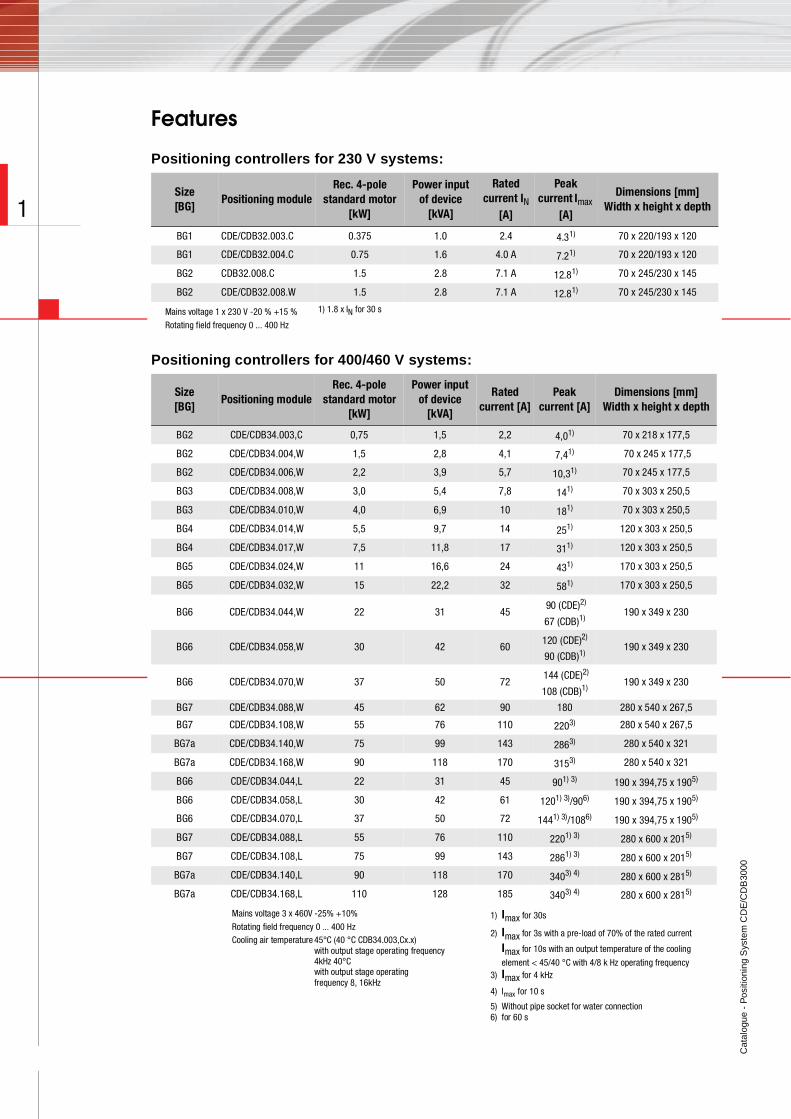
Features
Positioning controllers for 230 V systems:
Positioning controllers for 400/460 V systems:
Size[BG]
Positioning moduleRec. 4-pole
standard motor [kW]
Power input of device
[kVA]
Rated current IN
[A]
Peak current Imax
[A]
Dimensions [mm]Width x height x depth
BG1 CDE/CDB32.003.C 0.375 1.0 2.4 4.31) 70 x 220/193 x 120
BG1 CDE/CDB32.004.C 0.75 1.6 4.0 A 7.21) 70 x 220/193 x 120
BG2 CDB32.008.C 1.5 2.8 7.1 A 12.81) 70 x 245/230 x 145
BG2 CDE/CDB32.008.W 1.5 2.8 7.1 A 12.81) 70 x 245/230 x 145
Mains voltage 1 x 230 V -20 % +15 %
Rotating field frequency 0 ... 400 Hz
1) 1.8 x IN for 30 s
Size[BG]
Positioning moduleRec. 4-pole
standard motor [kW]
Power input of device
[kVA]
Rated current [A]
Peak current [A]
Dimensions [mm]Width x height x depth
BG2 CDE/CDB34.003,C 0,75 1,5 2,2 4,01) 70 x 218 x 177,5
BG2 CDE/CDB34.004,W 1,5 2,8 4,1 7,41) 70 x 245 x 177,5
BG2 CDE/CDB34.006,W 2,2 3,9 5,7 10,31) 70 x 245 x 177,5
BG3 CDE/CDB34.008,W 3,0 5,4 7,8 141) 70 x 303 x 250,5
BG3 CDE/CDB34.010,W 4,0 6,9 10 181) 70 x 303 x 250,5
BG4 CDE/CDB34.014,W 5,5 9,7 14 251) 120 x 303 x 250,5
BG4 CDE/CDB34.017,W 7,5 11,8 17 311) 120 x 303 x 250,5
BG5 CDE/CDB34.024,W 11 16,6 24 431) 170 x 303 x 250,5
BG5 CDE/CDB34.032,W 15 22,2 32 581) 170 x 303 x 250,5
BG6 CDE/CDB34.044,W 22 31 45 90 (CDE)2)
67 (CDB)1)190 x 349 x 230
BG6 CDE/CDB34.058,W 30 42 60120 (CDE)2)
90 (CDB)1)190 x 349 x 230
BG6 CDE/CDB34.070,W 37 50 72 144 (CDE)2)
108 (CDB)1)190 x 349 x 230
BG7 CDE/CDB34.088,W 45 62 90 180 280 x 540 x 267,5
BG7 CDE/CDB34.108,W 55 76 110 2203) 280 x 540 x 267,5
BG7a CDE/CDB34.140,W 75 99 143 2863) 280 x 540 x 321
BG7a CDE/CDB34.168,W 90 118 170 3153) 280 x 540 x 321
BG6 CDE/CDB34.044,L 22 31 45 901) 3) 190 x 394,75 x 1905)
BG6 CDE/CDB34.058,L 30 42 61 1201) 3)/906) 190 x 394,75 x 1905)
BG6 CDE/CDB34.070,L 37 50 72 1441) 3)/1086) 190 x 394,75 x 1905)
BG7 CDE/CDB34.088,L 55 76 110 2201) 3) 280 x 600 x 2015)
BG7 CDE/CDB34.108,L 75 99 143 2861) 3) 280 x 600 x 2015)
BG7a CDE/CDB34.140,L 90 118 170 3403) 4) 280 x 600 x 2815)
BG7a CDE/CDB34.168,L 110 128 185 3403) 4) 280 x 600 x 2815)
Mains voltage 3 x 460V -25% +10%
Rotating field frequency 0 ... 400 Hz Cooling air temperature 45°C (40 °C CDB34.003,Cx.x)
with output stage operating frequency 4kHz 40°C with output stage operating frequency 8, 16kHz
1) Imax for 30s
2) Imax for 3s with a pre-load of 70% of the rated current
Imax for 10s with an output temperature of the cooling
element < 45/40 °C with 4/8 k Hz operating frequency3) Imax for 4 kHz
4) Imax for 10 s
5) Without pipe socket for water connection6) for 60 s
Cat
alog
ue -
Pos
ition
ing
Sys
tem
CD
E/C
DB
3000
1 - 1
1
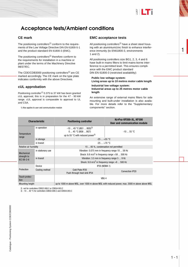
Acceptance tests/Ambient conditions
CE mark
The positioning controllers1) conform to the require-ments of the Low Voltage Directive DIN EN 61800-5-1 and the product standard EN 61800-3 (EMC).
The positioning controllers1) therefore conform to the requirements for installation in a machine or plant under the terms of the Machinery Directive 98/37/EC.
The CDE/CDB3000 positioning controllers1) are CE marked accordingly. The CE mark on the type plate indicates conformity with the above Directives.
cUL approbation
Positioning controller1) 0.375 to 37 kW has been grantedcUL approval, this is in preparation for the 47 - 90 kWrange. cUL approval is comparable to approval to ULand CSA.
1) Also applies to user and communication module
EMC acceptance tests
All positioning controllers1) have a sheet steel hous-ing with an aluminium/zinc finish to enhance interfer-ence immunity (to EN61800-3, environments 1 and 2).
All positioning controllers size BG1, 2, 3, 4 and 6 have built-in mains filters to limit mains-borne inter-ference to a permitted level. This ensures compli-ance with the EMC product standard DIN EN 61800-3 (restricted availability):
Public low voltage system:Living areas up to 10 metres motor cable length
Industrial low voltage system:Industrial areas up to 25 metres motor cable length
An extensive range of external mains filters for sidemounting and built-under installation is also availa-ble. For more details refer to the "Supplementarycomponents" section.
2) not for controllers CDB32.008.C or CDB34.003.C3) -10 ... 40 °C for controllers CDB32.008.C and CDB34.003.C
Characteristic Positioning controllerKEYPAD KP200-XL, KP300
User and communication module
Temperature range
in operation -10 ... 45 °C (BG1 ... BG5)3)
0 ... 45 °C (BG6 ... BG7)
up to 55 °C with reduced power2)
-10 ... 55 °C
in storage -25 ... +55 °C
in transit -25 ... +70 °C
Relative air humidity 15 ... 85 %, condensation not permitted
Mechanical strength to IEC 68-2-6
in stationary use Vibration: 0.075 mm in frequency range 10 ... 58 Hz
Shock: 9.8 m/s2 in frequency range >58 ... 500 Hz
in transit Vibration: 3.5 mm in frequency range 5 ... 9 Hz
Shock: 9.8 m/s2 in frequency range >9 ... 500 Hz
ProtectionDevice IP20 (NEMA 1)
Cooling method Cold Plate IP20Push-through heat sink IP54
Convection IP20
Touch protec-tion
VBG 4
Mounting height up to 1000 m above MSL, over 1000 m above MSL with reduced power, max. 2000 m above above MSL
Cat
alog
ue -
Pos
ition
ing
Sys
tem
CD
E/C
DB
3000
1 - 2
1
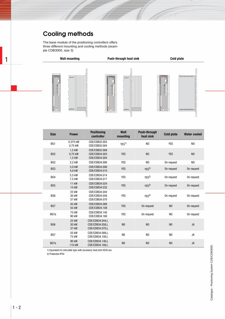
Cooling methodsThe base module of the positioning controllers offers three different mounting and cooling methods (exam-ple CDB3000, size 3)
Wall mounting Push-through heat sink Cold plate
WARNINGCapacitor discharge
time > 3 min.
Pay attention to the
operation manual!
ACHTUNGKondensatorent-
ladezeit > 3 Min.
Betriebsanleitung
beachten!
Ω
,5
WARNINGCapacitor discharge
time > 3 min.
Pay attention to the
operation manual!
ACHTUNGKondensatorent-
ladezeit > 3 Min.
Betriebsanleitung
beachten!
Ω
,5
WARNINGCapacitor discharge
time > 3 min.
Pay attention to the
operation manual!
ACHTUNGKondensatorent-
ladezeit > 3 Min.
Betriebsanleitung
beachten!
Ω
,5
Size PowerPositioning controller
Wallmounting
Push-through heat sink
Cold plate Water cooled
BG10,375 kW0,75 kW
CDE/CDB32.003CDE/CDB32.004 YES1) NO YES NO
BG21,5 kW
0,75 kW1,5 kW
CDE/CDB32.008CDE/CDB34.003CDE/CDB34.004
YES NO YES NO
BG2 2,2 kW CDE/CDB34.006 YES NO On request NO
BG33,0 kW4,0 kW
CDE/CDB34.008CDE/CDB34.010
YES YES2) On request On request
BG45,5 kW7,5 kW
CDE/CDB34.014CDE/CDB34.017
YES YES2) On request On request
BG511 kW15 kW
CDE/CDB34.024CDE/CDB34.032
YES YES2) On request On request
BG622 kW30 kW37 kW
CDE/CDB34.044CDE/CDB34.058CDE/CDB34.070
YES YES2) On request On request
BG745 kW55 kW
CDE/CDB34.088CDE/CDB34.108
YES On request NO On request
BG7a75 kW90 kW
CDE/CDB34.140CDE/CDB34.168
YES On request NO On request
BG622 kW30 kW37 kW
CDE/CDB34.044,LCDE/CDB34.058,LCDE/CDB34.070,L
NO NO NO JA
BG755 kW75 kW
CDE/CDB34.088,LCDE/CDB34.108,L
NO NO NO JA
BG7a90 kW
110 kWCDE/CDB34.140,LCDE/CDB34.168,L
NO NO NO JA
1) Equivalent to cold plate type with accessory heat sink HS3X.xxx
2) Protection IP54
Cat
alog
ue -
Pos
ition
ing
Sys
tem
CD
E/C
DB
3000
1 - 3
1
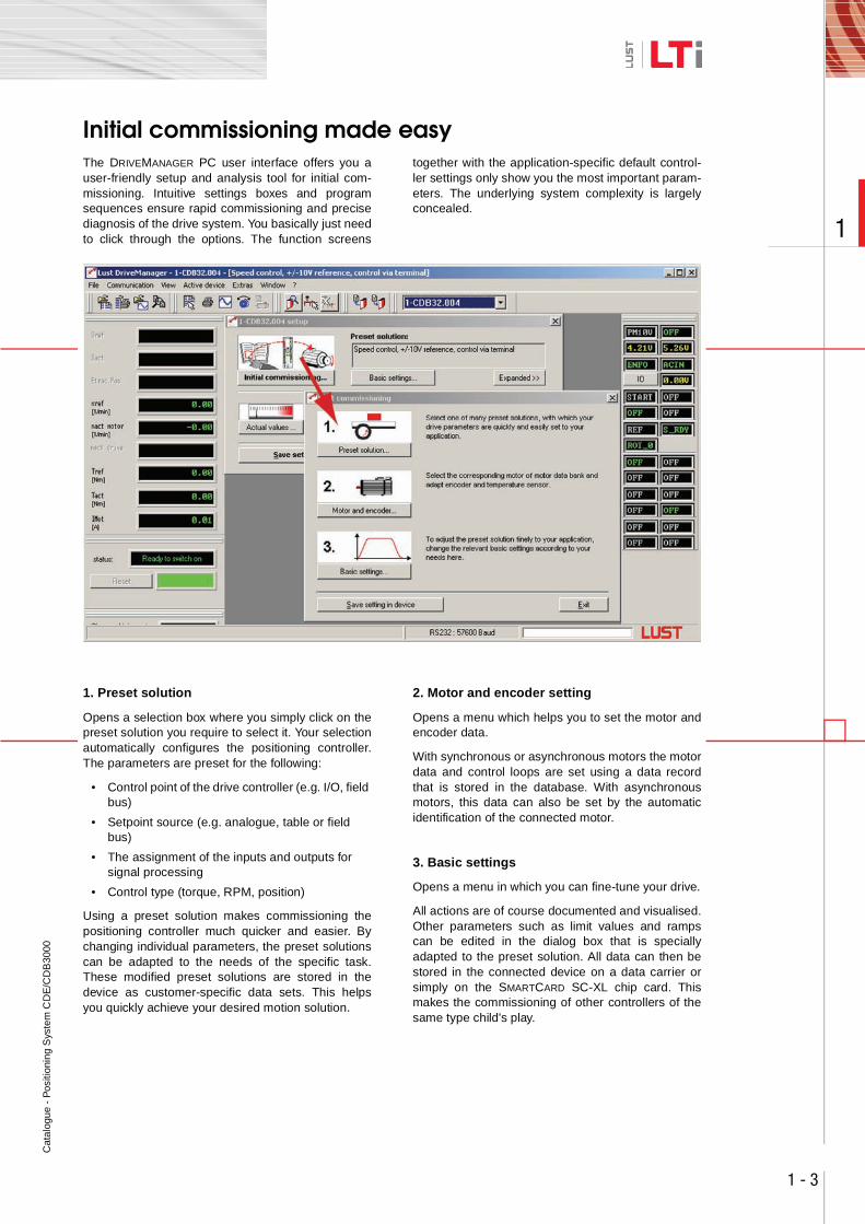
Initial commissioning made easyThe DRIVEMANAGER PC user interface offers you auser-friendly setup and analysis tool for initial com-missioning. Intuitive settings boxes and programsequences ensure rapid commissioning and precisediagnosis of the drive system. You basically just needto click through the options. The function screens
together with the application-specific default control-ler settings only show you the most important param-eters. The underlying system complexity is largelyconcealed.
1. Preset solution
Opens a selection box where you simply click on thepreset solution you require to select it. Your selectionautomatically configures the positioning controller.The parameters are preset for the following:
• Control point of the drive controller (e.g. I/O, field bus)
• Setpoint source (e.g. analogue, table or field bus)
• The assignment of the inputs and outputs for signal processing
• Control type (torque, RPM, position)
Using a preset solution makes commissioning thepositioning controller much quicker and easier. Bychanging individual parameters, the preset solutionscan be adapted to the needs of the specific task.These modified preset solutions are stored in thedevice as customer-specific data sets. This helpsyou quickly achieve your desired motion solution.
2. Motor and encoder setting
Opens a menu which helps you to set the motor andencoder data.
With synchronous or asynchronous motors the motordata and control loops are set using a data recordthat is stored in the database. With asynchronousmotors, this data can also be set by the automaticidentification of the connected motor.
3. Basic settings
Opens a menu in which you can fine-tune your drive.
All actions are of course documented and visualised.Other parameters such as limit values and rampscan be edited in the dialog box that is speciallyadapted to the preset solution. All data can then bestored in the connected device on a data carrier orsimply on the SMARTCARD SC-XL chip card. Thismakes the commissioning of other controllers of thesame type child's play.
Cat
alog
ue -
Pos
ition
ing
Sys
tem
CD
E/C
DB
3000
1 - 4
1
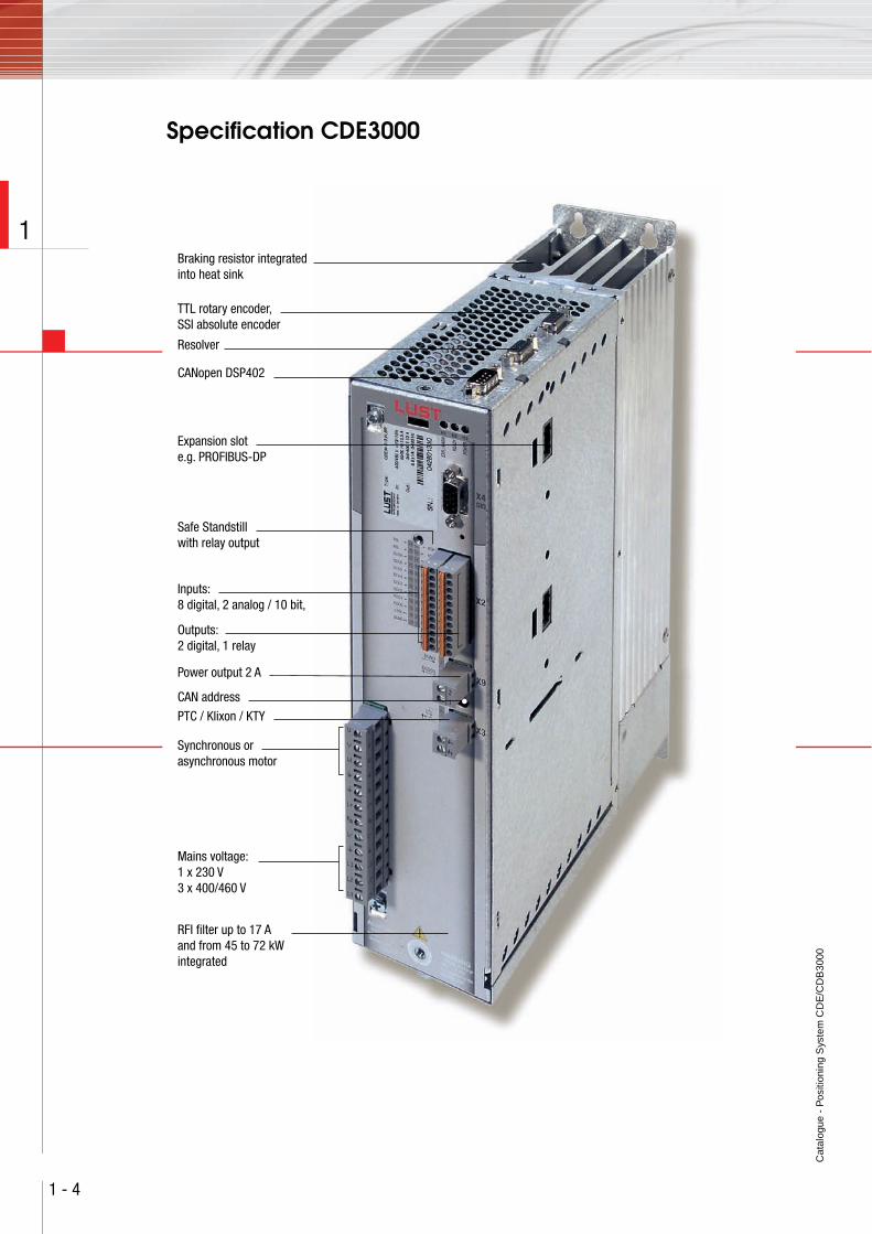
Specification CDE3000
Braking resistor integrated into heat sink
TTL rotary encoder,SSI absolute encoder
Resolver
CANopen DSP402
Expansion slote.g. PROFIBUS-DP
Safe Standstill with relay output
PTC / Klixon / KTY
Mains voltage:1 x 230 V3 x 400/460 V
Synchronous or asynchronous motor
RFI filter up to 17 A and from 45 to 72 kWintegrated
Outputs:2 digital, 1 relay
Inputs:8 digital, 2 analog / 10 bit,
Power output 2 A
CAN address
Cat
alog
ue -
Pos
ition
ing
Sys
tem
CD
E/C
DB
3000
1 - 5
1
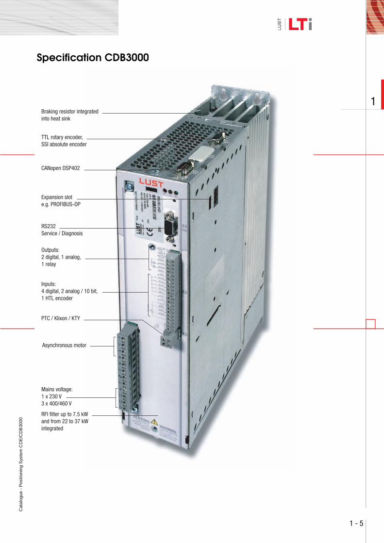
Specification CDB3000
Braking resistor integrated into heat sink
TTL rotary encoder,SSI absolute encoder
CANopen DSP402
Expansion slote.g. PROFIBUS-DP
RS232Service / Diagnosis
PTC / Klixon / KTY
Mains voltage:1 x 230 V3 x 400/460 V
Asynchronous motor
RFI filter up to 7.5 kW and from 22 to 37 kWintegrated
Outputs:2 digital, 1 analog,1 relay
Inputs:4 digital, 2 analog / 10 bit,1 HTL encoder
Cat
alog
ue -
Pos
ition
ing
Sys
tem
CD
E/C
DB
3000
1 - 6
1
ECOPOS — Positioning at its finestThe CDE/CDB3000 drive controllers are optimisedfor the positioning of electric drives. Alternatively,operation of the drive can also be speed or torquecontrolled.
The preset solutions provide a wide range of optionsfor setting the driving profile.
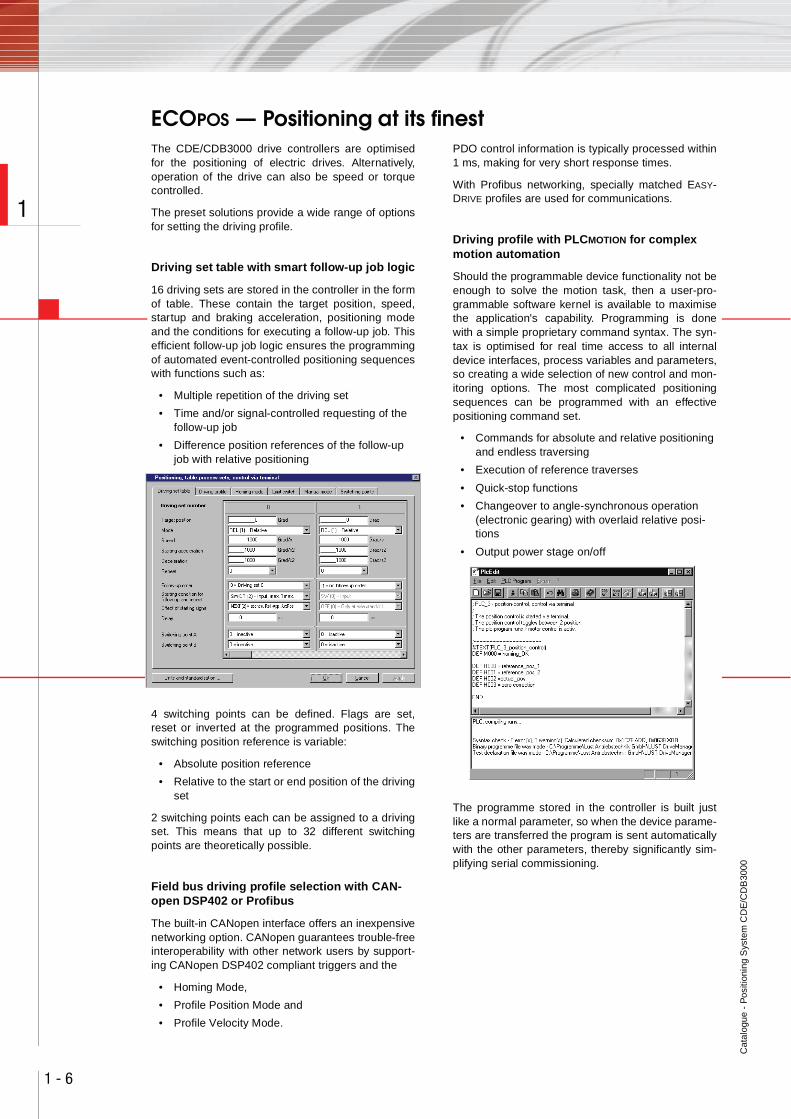
Driving set table with smart follow-up job logic
16 driving sets are stored in the controller in the formof table. These contain the target position, speed,startup and braking acceleration, positioning modeand the conditions for executing a follow-up job. Thisefficient follow-up job logic ensures the programmingof automated event-controlled positioning sequenceswith functions such as:
• Multiple repetition of the driving set
• Time and/or signal-controlled requesting of the follow-up job
• Difference position references of the follow-up job with relative positioning
4 switching points can be defined. Flags are set,reset or inverted at the programmed positions. Theswitching position reference is variable:
• Absolute position reference
• Relative to the start or end position of the drivingset
2 switching points each can be assigned to a drivingset. This means that up to 32 different switchingpoints are theoretically possible.
Field bus driving profile selection with CAN-open DSP402 or Profibus
The built-in CANopen interface offers an inexpensivenetworking option. CANopen guarantees trouble-freeinteroperability with other network users by support-ing CANopen DSP402 compliant triggers and the
• Homing Mode,
• Profile Position Mode and
• Profile Velocity Mode.
PDO control information is typically processed within1 ms, making for very short response times.
With Profibus networking, specially matched EASY-DRIVE profiles are used for communications.
Driving profile with PLCMOTION for complex motion automation
Should the programmable device functionality not beenough to solve the motion task, then a user-pro-grammable software kernel is available to maximisethe application's capability. Programming is donewith a simple proprietary command syntax. The syn-tax is optimised for real time access to all internaldevice interfaces, process variables and parameters,so creating a wide selection of new control and mon-itoring options. The most complicated positioningsequences can be programmed with an effectivepositioning command set.
• Commands for absolute and relative positioning and endless traversing
• Execution of reference traverses
• Quick-stop functions
• Changeover to angle-synchronous operation (electronic gearing) with overlaid relative posi-tions
• Output power stage on/off
The programme stored in the controller is built justlike a normal parameter, so when the device parame-ters are transferred the program is sent automaticallywith the other parameters, thereby significantly sim-plifying serial commissioning.
Cat
alog
ue -
Pos
ition
ing
Sys
tem
CD
E/C
DB
3000
1 - 7
1
High dynamics and superior control quality
At the heart of the software is the position profilegenerator that computes the a smooth and time-opti-mised setpoint trajectory for the position controllerfrom a selected driving set. The fact that the setpointtrajectory is generated online means that a new mod-ified driving set can be transferred and started dur-ing ongoing positioning inside just 1ms.
• Short cycle times thanks to a setup time of just 1 ms
• Absolute or relative positioning, endless travers-ing
• Linear acceleration and braking ramps or with adjustable jolt limiting for motions that are easy on the mechanics
• Jolt-limited changes to the driving job in just 1 ms even during ongoing positioning
The position control loop with its sampling frequencyof 4 kHz (250 μs) and an overlaid pre-control struc-ture creates optimum dynamic characteristics and ahigh control quality.
Comprehensive basic functions for position-ing
Positioning is based on comprehensive basic func-tions in the hardware or software which can be usedindependently of a preset solution.
• Application-specific units such as mm, degrees or even user-specific units allow settings in your own language
• Correction-free calculation of uneven gear ratios for rotary tables or indexing conveyors
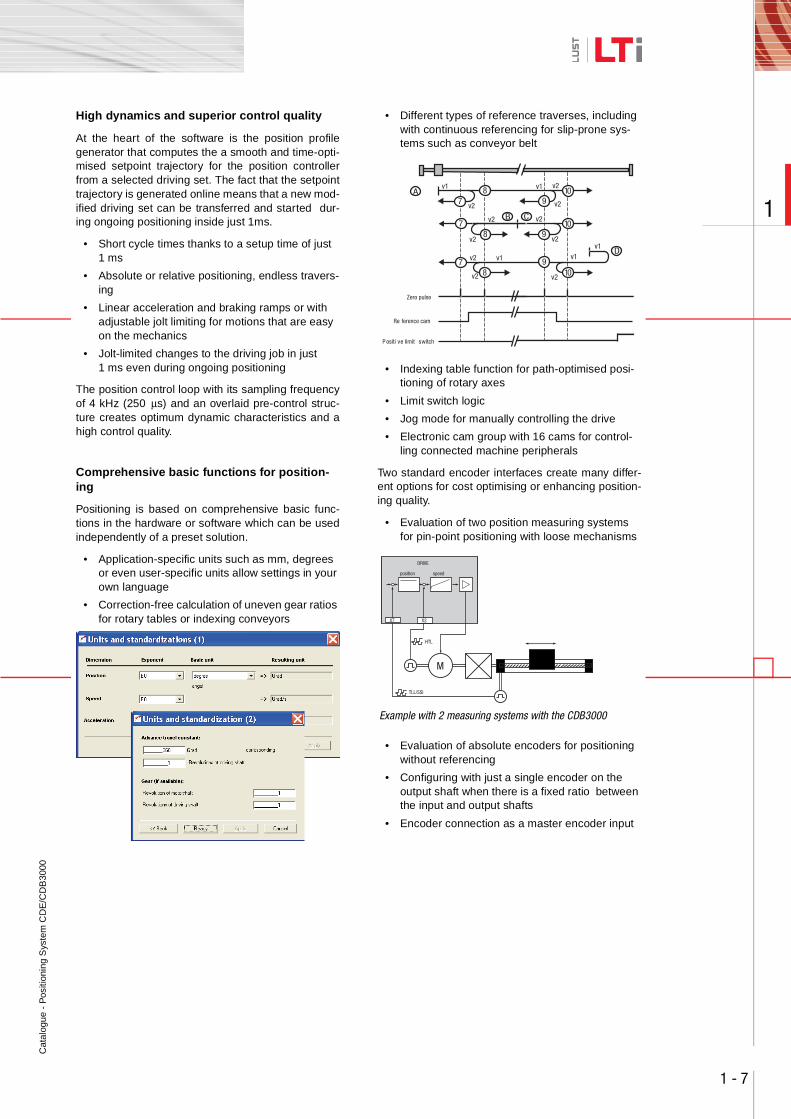
• Different types of reference traverses, including with continuous referencing for slip-prone sys-tems such as conveyor belt
• Indexing table function for path-optimised posi-tioning of rotary axes
• Limit switch logic
• Jog mode for manually controlling the drive
• Electronic cam group with 16 cams for control-ling connected machine peripherals
Two standard encoder interfaces create many differ-ent options for cost optimising or enhancing position-ing quality.
• Evaluation of two position measuring systems for pin-point positioning with loose mechanisms
• Evaluation of absolute encoders for positioning without referencing
• Configuring with just a single encoder on the output shaft when there is a fixed ratio between the input and output shafts
• Encoder connection as a master encoder input
Zero pulse
Re ference cam
P ositi ve limit switch
A
B Cv2 v2
v2v2
Dv1
v1v1v2
v2 v2
v1 v1
v2
v2
v2 9
9
9
7
7
7
8
8
8
10
10
10
M
TLL/SSI
position speed
X7 X2
HTL
DRIVE
Example with 2 measuring systems with the CDB3000
Cat
alog
ue -
Pos
ition
ing
Sys
tem
CD
E/C
DB
3000
1 - 8
1
ServicesLTi offers a wide range of information on the Internet.Whether you are looking for more detailed technicalinformation on our products or on project planningand design, or want to contact your nearest LTi rep-resentative - just visit our website at
http://www.lt-i.com
Software Update Service
We are continuously improving the quality of thedrive system in the interests of product development.Our Software Update Service will brief you on inno-vations and enhancements to individual firmwareversions.
This information, together with the latest firmware, isavailable for downloading on our Info Server.
Design-In
Professional project management that keeps you towithin deadlines and budgets is an important ele-ment of our joint success. The sooner you get tomarket with your new solution the better. That's whywe can support you in
• analysing requirements
• planning the drive design
• creating the functional specification
• the total cost analysis
• project management
Logistics
To make ordering a routine exercise and reduce oreven eliminate unnecessary formalities, the entireprocess is co-ordinated, from planning throughordering to spare parts supplies.
After-sales
You can call on our service and support whereverand whenever you need it. With our flexibility, fastresponse times, superior technical know-how andextensive user experience, we can offer a wide rangeof services, including
• on-site commissioning
• advice and training
• repairs/service concept
Helpline
Our Helpline can assist you with:
• the telephone commissioning of standard prod-ucts and systems
• evaluating error and diagnostic displays
• locating and dealing with repeatable faults, and
• software updates.
You can reach us:
Mon.-Thur.: 8 a.m. - 4.30 p.m.Fri.: 8 a.m. - 4 p.m.
Tel. +49(0) 6441/966-180
Fax: +49(0) 6441/966-177e-mail: [email protected]
Downloads:• You will find detailed information on our prod-
ucts in the "Downloads" section of our website.
Ca
talo
gue
- P
ositi
onin
g S
yste
m C
DE
/CD
B30
00
2 - 1
2
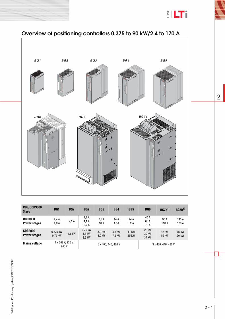
Overview of positioning controllers 0.375 to 90 kW/2.4 to 170 A
CDE/CDB3000 Sizes
BG1 BG2 BG2 BG3 BG4 BG5 BG6 BG7a1) BG7b1)
CDE3000Power stages
2,4 A4,0 A
7,1 A2,2 A4,1 A5,7 A
7,8 A10 A
14 A17 A
24 A32 A
45 A60 A72 A
90 A110 A
143 A170 A
CDB3000Power stages
0,375 kW0,75 kW
1,5 kW0,75 kW1,5 kW2,2 kW
3,0 kW4,0 kW
5,5 kW7,5 kW
11 kW15 kW
22 kW30 kW37 kW
47 kW55 kW
75 kW90 kW
Mains voltage 1 x 208 V, 230 V,240 V
3 x 400, 440, 460 V 3 x 400, 440, 480 V
X1
L3
U
V
W
RB+RB
L-
L1
L2
Ω
,5
Ca
talo
gue
- P
ositi
onin
g S
yste
m C
DE
/CD
B30
00
2 - 2
2
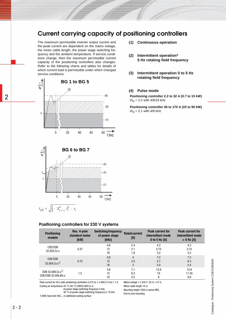
Current carrying capacity of positioning controllersThe maximum permissible inverter output current andthe peak current are dependent on the mains voltage,the motor cable length, the power stage switching fre-quency and the ambient temperature. If service condi-tions change, then the maximum permissible currentcapacity of the positioning controllers also changes.Refer to the following charts and tables for details ofwhich current load is permissible under which changedservice conditions.
(1) Continuous operation
(2) Intermittent operation* 5 Hz rotating field frequency
(3) Intermittent operation 0 to 5 Hz rotating field frequency
(4) Pulse modePositioning controller 2.2 to 32 A (0.7 to 15 kW)I/IN = 2.2 with 4/8/16 kHz
Positioning controller 45 to 170 A (22 to 90 kW)I/IN = 2.1 with 4/8 kHz
5 25 40 45 50
1
IIN
(1)
f [Hz]
(2)
(3)
(4)
BG 1 to BG 5
5 35 40 45 50
1
IIN
Imax
(1)
f [Hz]
(2)
(3)
(4)
BG 6 to BG 7
Ief f1T--- Σn
i 1=I2i ti⋅ ⋅=
Positioning controllers for 230 V systems
Positioningmodule
Rec. 4-pole standard motor
[kW]
Switching frequency of power stage
[kHz]
Rated current [A]
Peak current for intermittent mode
0 to 5 Hz [A]
Peak current for intermittent mode
> 5 Hz [A]
CDE/CDB 32.003,Cx.x
0.37 4.81216
2.42.11.8
4.33.753.2
4.33.753.2
CDE/CDB
32.004,Cx.x1) 0.75 4.81216
43.53
7.25.75.0
7.26.35.4
CDB 32.008,Cx.x1)
CDE/CDB 32.008,Wx.x1.5
4.81216
7.16.35.5
12.8108
12.811.35
9.9
Peak current for 30 s with positioning controllers 0.375 to 1.5 kW/2.4 A to 7.1 A
Cooling air temperature 45 °C (40 °C CDB32.008.Cx.x) at power stage switching frequency 4 kHz
40 °C at power stage switching frequency 8, 16 kHz1) With heat sink HS3... or additional cooling surface
Mains voltage 1 x 230 V -20 % +15 %
Motor cable length 10 m
Mounting height 1000 m above MSLEnd-to-end mounting
Ca
talo
gue
- P
ositi
onin
g S
yste
m C
DE
/CD
B30
00
2 - 3
2
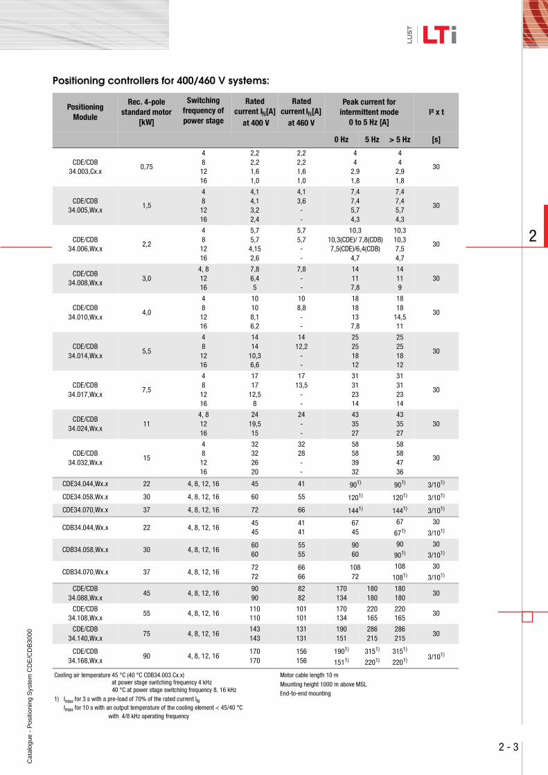
Positioning controllers for 400/460 V systems:
PositioningModule
Rec. 4-pole standard motor
[kW]
Switching frequency of power stage
Rated current IN[A]
at 400 V
Rated current IN[A]
at 460 V
Peak current for intermittent mode
0 to 5 Hz [A]I² x t
0 Hz 5 Hz > 5 Hz [s]
CDE/CDB34.003,Cx.x
0,75
48
1216
2,22,21,61,0
2,22,21,61,0
44
2,91,8
44
2,91,8
30
CDE/CDB34.005,Wx.x
1,5
48
1216
4,14,13,22,4
4,13,6--
7,47,45,74,3
7,47,45,74,3
30
CDE/CDB34.006,Wx.x
2,2
48
1216
5,75,7
4,152,6
5,75,7--
10,310,3(CDE)/ 7,8(CDB)7,5(CDE)/6,4(CDB)
4,7
10,310,37,54,7
30
CDE/CDB34.008,Wx.x
3,04, 81216
7,86,45
7,8--
14117,8
14119
30
CDE/CDB34.010,Wx.x
4,0
48
1216
10108,16,2
108,8--
1818137,8
1818
14,511
30
CDE/CDB34.014,Wx.x
5,5
48
1216
1414
10,36,6
1412,2
--
25251812
25251812
30
CDE/CDB34.017,Wx.x
7,5
48
1216
1717
12,58
1713,5
--
31312314
31312314
30
CDE/CDB34.024,Wx.x
114, 81216
2419,515
24--
433527
433527
30
CDE/CDB34.032,Wx.x
15
48
1216
32322620
3228--
58583932
58584736
30
CDE34.044,Wx.x 22 4, 8, 12, 16 45 41 901) 901) 3/101)
CDE34.058,Wx.x 30 4, 8, 12, 16 60 55 1201) 1201) 3/101)
CDE34.070,Wx.x 37 4, 8, 12, 16 72 66 1441) 1441) 3/101)
CDB34.044,Wx.x 22 4, 8, 12, 1645 45
4141
67 45
67
671)
30
3/101)
CDB34.058,Wx.x 30 4, 8, 12, 1660 60
5555
9060
90
901)30
3/101)
CDB34.070,Wx.x 37 4, 8, 12, 1672 72
6666
10872
108
1081)
30
3/101)
CDE/CDB34.088,Wx.x
45 4, 8, 12, 1690 90
8282
170134
180180
180180
30
CDE/CDB34.108,Wx.x
55 4, 8, 12, 16110 110
101101
170134
220165
220165
30
CDE/CDB34.140,Wx.x
75 4, 8, 12, 16143143
131131
190151
286215
286215
30
CDE/CDB34.168,Wx.x
90 4, 8, 12, 16170170
156156
1901)
1511)3151)
2201)3151)
2201) 3/101)
Cooling air temperature 45 °C (40 °C CDB34.003.Cx.x) at power stage switching frequency 4 kHz40 °C at power stage switching frequency 8, 16 kHz
1) Imax for 3 s with a pre-load of 70% of the rated current IN Imax for 10 s with an output temperature of the cooling element < 45/40 °C with 4/8 kHz operating frequency
Motor cable length 10 m
Mounting height 1000 m above MSLEnd-to-end mounting
Ca
talo
gue
- P
ositi
onin
g S
yste
m C
DE
/CD
B30
00
2 - 4
2
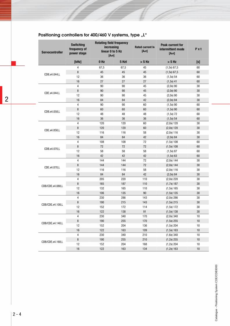
Positioning controllers for 400/460 V systems, type „L“
Servocontroller
Switchingfrequency ofpower stage
Rotating field frequency increasing
linear 0 to 5 Hz[Aeff]
Rated current IN[Aeff]
Peak current forintermittent mode
[Aeff]I² x t
[kHz] 0 Hz 5 Hzt > 5 Hz > 5 Hz [s]
CDB.x4.044,L
4 67,5 67,5 45 (1,5x) 67,5 60
8 45 45 45 (1,5x) 67,5 60
12 36 36 36 (1,5x) 54 60
16 27 27 27 (1,5x) 41 60
CDE.x4.044,L
4 90 90 45 (2,0x) 90 30
8 90 90 45 (2,0x) 90 30
12 90 90 45 (2,0x) 90 30
16 84 84 42 (2,0x) 84 30
CDB.x4.058,L
4 90 90 60 (1,5x) 90 60
8 60 60 60 (1,5x) 90 60
12 48 48 48 (1,5x) 72 60
16 36 36 36 (1,5x) 54 60
CDE.x4.058,L
4 120 120 60 (2,0x) 120 30
8 120 120 60 (2,0x) 120 30
12 116 116 58 (2,0x) 116 30
16 84 84 42 (2,0x) 84 30
CDB.x4.070,L
4 108 108 72 (1,5x) 108 60
8 72 72 72 (1,5x) 108 60
12 58 58 58 (1,5x) 87 60
16 42 42 42 (1,5x) 63 60
CDE.x4.070,L
4 144 144 72 (2,0x) 144 30
8 144 144 72 (2,0x) 144 30
12 116 116 58 (2,0x) 116 30
16 84 84 42 (2,0x) 84 30
CDB/CDE.x4.088,L
4 205 220 110 (2,0x) 220 30
8 165 187 110 (1,7x) 187 30
12 132 165 110 (1,5x) 165 30
16 106 135 90 (1,5x) 135 30
CDB/CDE.x4.108,L
4 230 286 143 (2,0x) 286 30
8 190 215 143 (1,5x) 215 30
12 152 172 114 (1,5x) 172 30
16 122 138 91 (1,5x) 138 30
CDB/CDE.x4.140,L
4 230 340 170 (2,0x) 340 10
8 190 255 170 (1,5x) 255 10
12 152 204 136 (1,5x) 204 10
16 122 163 109 (1,5x) 163 10
CDB/CDE.x4.168,L
4 230 340 210 (1,6x) 340 10
8 190 255 210 (1,2x) 255 10
12 152 204 168 (1,2x) 204 10
16 122 163 134 (1,2x) 163 10
Ca
talo
gue
- P
ositi
onin
g S
yste
m C
DE
/CD
B30
00
2 - 5
2
Notes:
Ca
talo
gue
- P
ositi
onin
g S
yste
m C
DE
/CD
B30
00
2 - 6
2
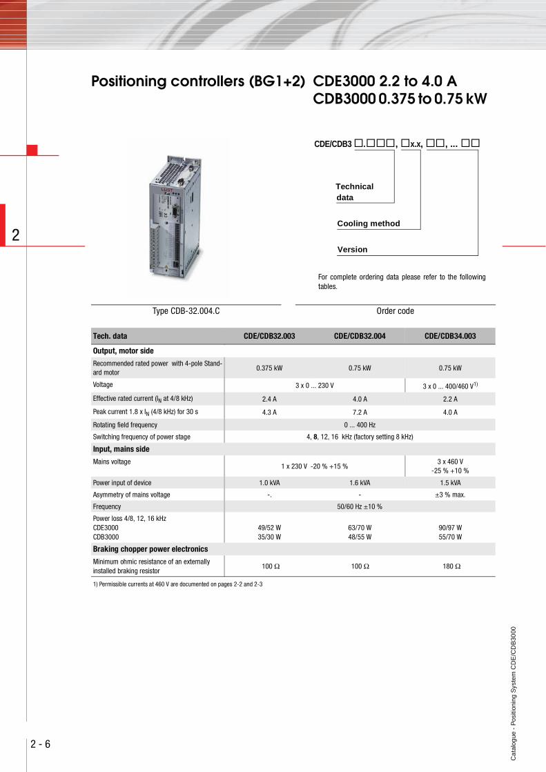
Positioning controllers (BG1+2) CDE3000 2.2 to 4.0 ACDB3000 0.375 to 0.75 kW
Type CDB-32.004.C Order code
CDE/CDB3 . , x.x, , ...
Cooling method
Version
Technicaldata
For complete ordering data please refer to the followingtables.
Tech. data CDE/CDB32.003 CDE/CDB32.004 CDE/CDB34.003
Output, motor side
Recommended rated power with 4-pole Stand-ard motor
0.375 kW 0.75 kW 0.75 kW
Voltage 3 x 0 ... 230 V 3 x 0 ... 400/460 V1)
Effective rated current (IN at 4/8 kHz) 2.4 A 4.0 A 2.2 A
Peak current 1.8 x IN (4/8 kHz) for 30 s 4.3 A 7.2 A 4.0 A
Rotating field frequency 0 ... 400 Hz
Switching frequency of power stage 4, 8, 12, 16 kHz (factory setting 8 kHz)
Input, mains side
Mains voltage1 x 230 V -20 % +15 %
3 x 460 V -25 % +10 %
Power input of device 1.0 kVA 1.6 kVA 1.5 kVA
Asymmetry of mains voltage -. - ±3 % max.
Frequency 50/60 Hz ±10 %
Power loss 4/8, 12, 16 kHzCDE3000CDB3000
49/52 W35/30 W
63/70 W48/55 W
90/97 W55/70 W
Braking chopper power electronics
Minimum ohmic resistance of an externally installed braking resistor
100 Ω 100 Ω 180 Ω
1) Permissible currents at 460 V are documented on pages 2-2 and 2-3
Ca
talo
gue
- P
ositi
onin
g S
yste
m C
DE
/CD
B30
00
2 - 7
2
.
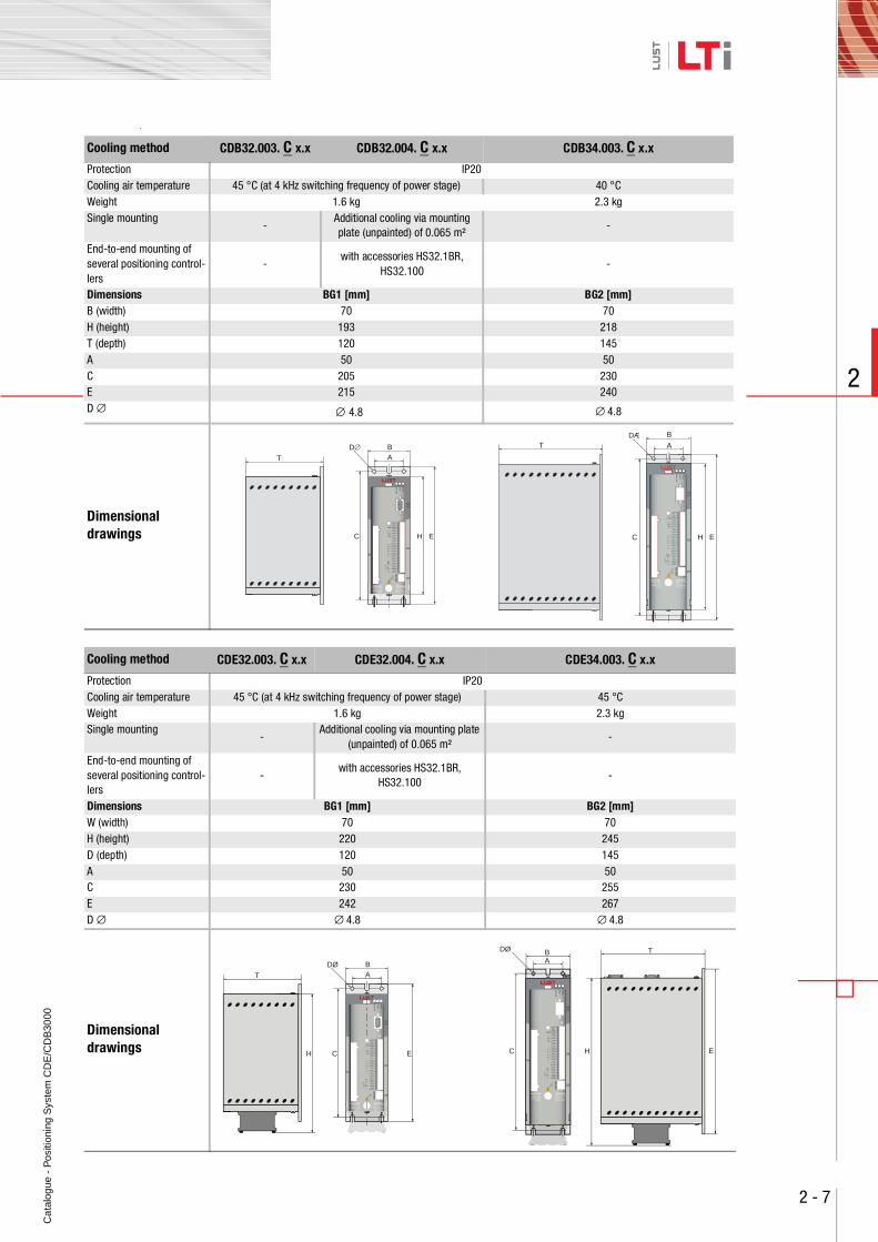
Cooling method CDB32.003. C x.x CDB32.004. C x.x CDB34.003. C x.x
Protection IP20Cooling air temperature 45 °C (at 4 kHz switching frequency of power stage) 40 °CWeight 1.6 kg 2.3 kgSingle mounting
-Additional cooling via mounting plate (unpainted) of 0.065 m²
-
End-to-end mounting of several positioning control-lers
-with accessories HS32.1BR,
HS32.100-
Dimensions BG1 [mm] BG2 [mm]B (width) 70 70H (height) 193 218T (depth) 120 145A 50 50C 205 230E 215 240D ∅ ∅ 4.8 ∅ 4.8
Dimensional drawings
Cooling method CDE32.003. C x.x CDE32.004. C x.x CDE34.003. C x.x
Protection IP20Cooling air temperature 45 °C (at 4 kHz switching frequency of power stage) 45 °CWeight 1.6 kg 2.3 kgSingle mounting
-Additional cooling via mounting plate
(unpainted) of 0.065 m²-
End-to-end mounting of several positioning control-lers
-with accessories HS32.1BR,
HS32.100-
Dimensions BG1 [mm] BG2 [mm]W (width) 70 70H (height) 220 245D (depth) 120 145A 50 50C 230 255E 242 267D ∅ ∅ 4.8 ∅ 4.8
Dimensional drawings
T
BA
HC E
D∅ T
H E
B
A
C
DÆ
T
BA
C E
DØ
H
T
H
B
C E
DØ
A
Ca
talo
gue
- P
ositi
onin
g S
yste
m C
DE
/CD
B30
00
2 - 8
2
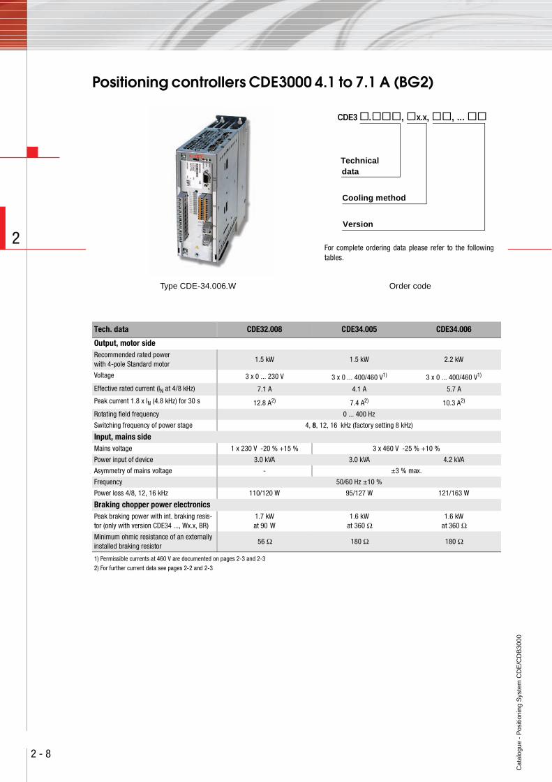
Positioning controllers CDE3000 4.1 to 7.1 A (BG2)
Type CDE-34.006.W Order code
CDE3 . , x.x, , ...
Cooling method
Version
Technicaldata
For complete ordering data please refer to the followingtables.
Tech. data CDE32.008 CDE34.005 CDE34.006
Output, motor sideRecommended rated powerwith 4-pole Standard motor
1.5 kW 1.5 kW 2.2 kW
Voltage 3 x 0 ... 230 V 3 x 0 ... 400/460 V1) 3 x 0 ... 400/460 V1)
Effective rated current (IN at 4/8 kHz) 7.1 A 4.1 A 5.7 A
Peak current 1.8 x IN (4.8 kHz) for 30 s 12.8 A2) 7.4 A2) 10.3 A2)
Rotating field frequency 0 ... 400 Hz
Switching frequency of power stage 4, 8, 12, 16 kHz (factory setting 8 kHz)
Input, mains sideMains voltage 1 x 230 V -20 % +15 % 3 x 460 V -25 % +10 %
Power input of device 3.0 kVA 3.0 kVA 4.2 kVA
Asymmetry of mains voltage - ±3 % max.
Frequency 50/60 Hz ±10 %
Power loss 4/8, 12, 16 kHz 110/120 W 95/127 W 121/163 W
Braking chopper power electronicsPeak braking power with int. braking resis-tor (only with version CDE34 ..., Wx.x, BR)
1.7 kW at 90 W
1.6 kWat 360 Ω
1.6 kWat 360 Ω
Minimum ohmic resistance of an externally installed braking resistor
56 Ω 180 Ω 180 Ω
1) Permissible currents at 460 V are documented on pages 2-3 and 2-3
2) For further current data see pages 2-2 and 2-3
Ca
talo
gue
- P
ositi
onin
g S
yste
m C
DE
/CD
B30
00
2 - 9
2
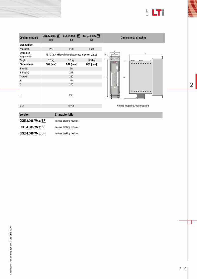
Cooling method,CDE32.008. W
x.x,CDE34.005. W
x.x,CDE34.006. W
x.xDimensional drawing
MechanismProtection IP20 IP20 IP20
Cooling airtemperature
45 °C (at 4 kHz switching frequency of power stage)
Weight 3.5 kg 3.5 kg 3.5 kg
Dimensions BG2 [mm] BG2 [mm] BG2 [mm]
B (width) 70
H (height) 247
T (depth) 220
A 40
C 270
E 260
D ∅ ∅ 4.8 Vertical mounting, wall mounting
Version Characteristic
CDE32.008.Wx.x,BR Internal braking resistor
CDE34.005.Wx.x,BR Internal braking resistor
CDE34.006.Wx.x,BR Internal braking resistor
T
H
BA
CE
DØ
Ca
talo
gue
- P
ositi
onin
g S
yste
m C
DE
/CD
B30
00
2 - 10
2
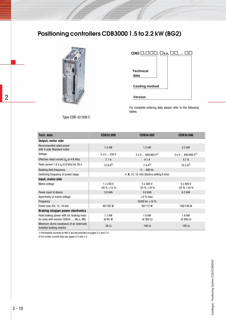
Positioning controllers CDB3000 1.5 to 2.2 kW (BG2)
Type CDB-32.008.C
CDB3 . , x.x, , ...
Cooling method
Version
Technicaldata
For complete ordering data please refer to the followingtables.
Tech. data CDB32.008 CDB34.005 CDB34.006
Output, motor sideRecommended rated powerwith 4-pole Standard motor
1.5 kW 1.5 kW 2.2 kW
Voltage 3 x 0 ... 230 V 3 x 0 ... 400/460 V1) 3 x 0 ... 400/460 V1)
Effective rated current (IN at 4/8 kHz) 7.1 A 4.1 A 5.7 A
Peak current 1.8 x IN (4.8 kHz) for 30 s 12.8 A2) 7.4 A2) 10.3 A2)
Rotating field frequency 0 ... 400 Hz
Switching frequency of power stage 4, 8, 12, 16 kHz (factory setting 8 kHz)
Input, mains sideMains voltage 1 x 230 V
-20 % +15 %3 x 460 V
-25 % +10 %3 x 460 V
-25 % +10 %
Power input of device 3.0 kVA 3.0 kVA 4.2 kVA
Asymmetry of mains voltage - ±3 % max.
Frequency 50/60 Hz ±10 %
Power loss 4/8, 12, 16 kHz 95/105 W 80/112 W 106/148 W
Braking chopper power electronicsPeak braking power with int. braking resis-tor (only with version CDB34 ..., Wx.x, BR)
1.7 kW at 90 W
1.6 kWat 360 Ω
1.6 kW at 360 Ω
Minimum ohmic resistance of an externally installed braking resistor
56 Ω 180 Ω 180 Ω
1) Permissible currents at 460 V are documented on pages 2-2 and 2-3
2) For further current data see pages 2-2 and 2-3
Ca
talo
gue
- P
ositi
onin
g S
yste
m C
DE
/CD
B30
00
2 - 11
2
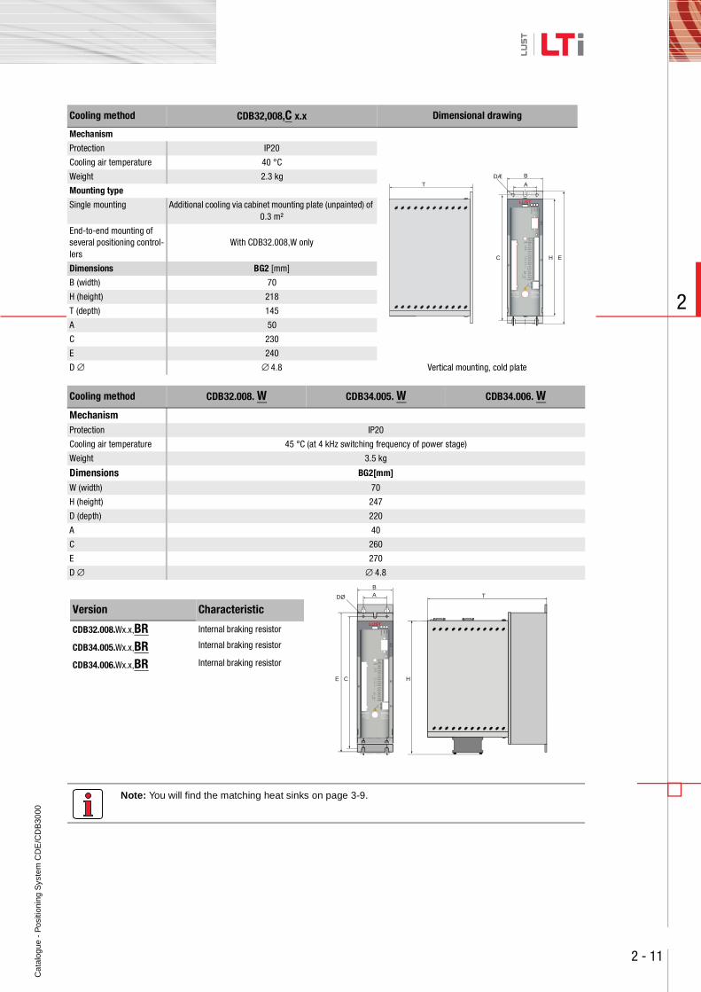
Note: You will find the matching heat sinks on page 3-9.
Cooling method CDB32,008,C x.x Dimensional drawing
Mechanism
Protection IP20
Cooling air temperature 40 °C
Weight 2.3 kg
Mounting type
Single mounting Additional cooling via cabinet mounting plate (unpainted) of 0.3 m²
End-to-end mounting of several positioning control-lers
With CDB32.008,W only
Dimensions BG2 [mm]
B (width) 70
H (height) 218
T (depth) 145
A 50
C 230
E 240
D ∅ ∅ 4.8 Vertical mounting, cold plate
Cooling method ,CDB32.008. W ,CDB34.005. W ,CDB34.006. W
MechanismProtection IP20
Cooling air temperature 45 °C (at 4 kHz switching frequency of power stage)
Weight 3.5 kg
Dimensions BG2[mm]
W (width) 70
H (height) 247
D (depth) 220
A 40
C 260
E 270
D ∅ ∅ 4.8
T
H E
B
A
C
DÆ
Version Characteristic
CDB32.008.Wx.x,BR Internal braking resistor
CDB34.005.Wx.x,BR Internal braking resistor
CDB34.006.Wx.x,BR Internal braking resistor
T
H
BA
CE
DØ
Ca
talo
gue
- P
ositi
onin
g S
yste
m C
DE
/CD
B30
00
2 - 12
2
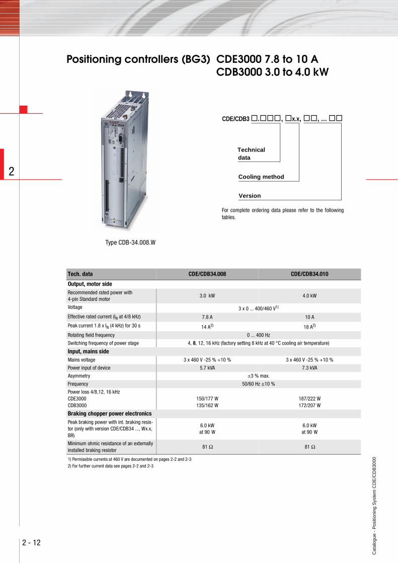
Positioning controllers (BG3) CDE3000 7.8 to 10 ACDB3000 3.0 to 4.0 kW
Type CDB-34.008.W
CDE/CDB3 . , x.x, , ...
Cooling method
Version
Technicaldata
For complete ordering data please refer to the followingtables.
Tech. data CDE/CDB34.008 CDE/CDB34.010
Output, motor sideRecommended rated power with 4-pin Standard motor
3.0 kW 4.0 kW
Voltage 3 x 0 ... 400/460 V1)
Effective rated current (IN at 4/8 kHz) 7.8 A 10 A
Peak current 1.8 x IN (4 kHz) for 30 s 14 A2) 18 A2)
Rotating field frequency 0 ... 400 Hz
Switching frequency of power stage 4, 8, 12, 16 kHz (factory setting 8 kHz at 40 °C cooling air temperature)
Input, mains sideMains voltage 3 x 460 V -25 % +10 % 3 x 460 V -25 % +10 %
Power input of device 5.7 kVA 7.3 kVA
Asymmetry ±3 % max.
Frequency 50/60 Hz ±10 %
Power loss 4/8,12, 16 kHzCDE3000CDB3000
150/177 W135/162 W
187/222 W172/207 W
Braking chopper power electronicsPeak braking power with int. braking resis-tor (only with version CDE/CDB34 ..., Wx.x, BR)
6.0 kWat 90 W
6.0 kWat 90 W
Minimum ohmic resistance of an externally installed braking resistor
81 Ω 81 Ω
1) Permissible currents at 460 V are documented on pages 2-2 and 2-3
2) For further current data see pages 2-2 and 2-3
Ca
talo
gue
- P
ositi
onin
g S
yste
m C
DE
/CD
B30
00
2 - 13
2
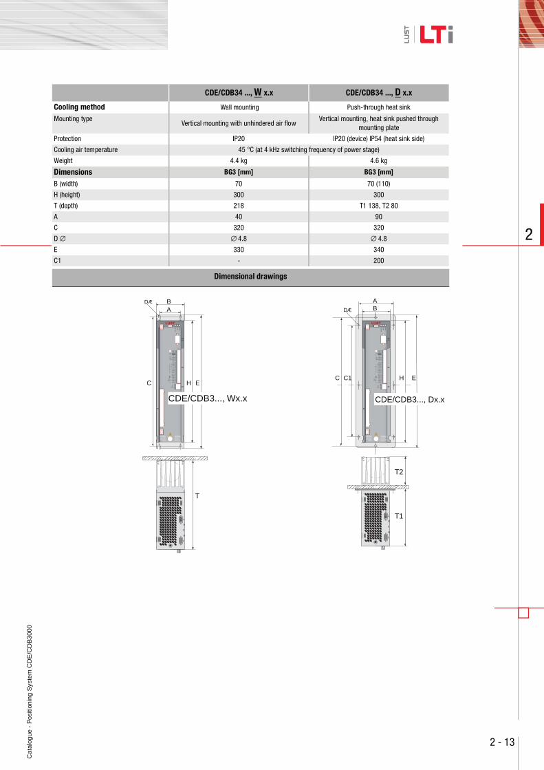
,CDE/CDB34 ..., W x.x ,CDE/CDB34 ..., D x.x
Cooling method Wall mounting Push-through heat sink
Mounting typeVertical mounting with unhindered air flow
Vertical mounting, heat sink pushed through mounting plate
Protection IP20 IP20 (device) IP54 (heat sink side)
Cooling air temperature 45 °C (at 4 kHz switching frequency of power stage)
Weight 4.4 kg 4.6 kg
Dimensions BG3 [mm] BG3 [mm]
B (width) 70 70 (110)
H (height) 300 300
T (depth) 218 T1 138, T2 80
A 40 90
C 320 320
D ∅ ∅ 4.8 ∅ 4.8
E 330 340
C1 - 200
Dimensional drawings
BA
HC E
DÆ
E
BA
HC1C
DÆ
WARNINGCapacitor dischargetime > 3 min.Pay attention to theoperation manual!
ACHTUNGKondensatorent-ladezeit > 3 Min.Betriebsanleitung
beachten!
,5
WARNINGCapacitor dischargetime > 3 min.Pay attention to theoperation manual!
ACHTUNGKondensatorent-ladezeit > 3 Min.Betriebsanleitung
beachten!
,5
CDE/CDB3..., Dx.xCDE/CDB3..., Wx.x
T
X5
X6
X7 T1
T2
X5
X6
X7
Ca
talo
gue
- P
ositi
onin
g S
yste
m C
DE
/CD
B30
00
2 - 14
2
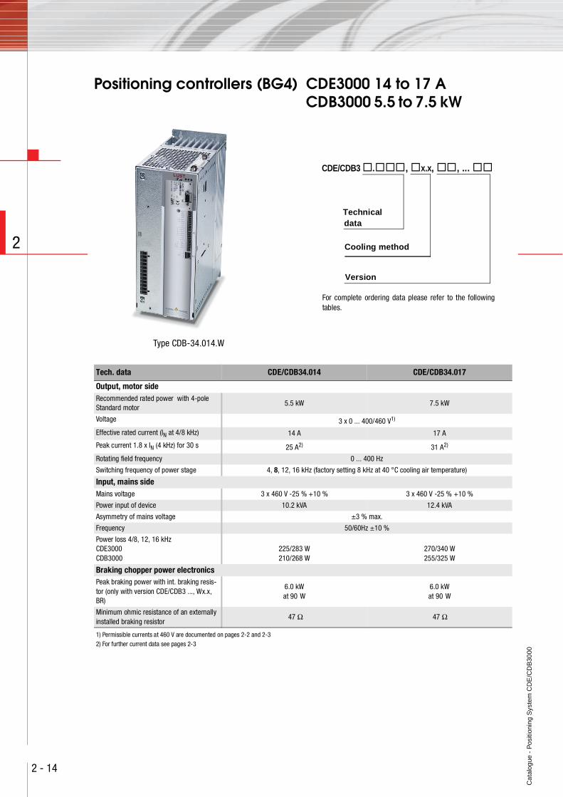
Positioning controllers (BG4) CDE3000 14 to 17 ACDB3000 5.5 to 7.5 kW
Type CDB-34.014.W
Tech. data CDE/CDB34.014 CDE/CDB34.017
Output, motor sideRecommended rated power with 4-pole Standard motor
5.5 kW 7.5 kW
Voltage 3 x 0 ... 400/460 V1)
Effective rated current (IN at 4/8 kHz) 14 A 17 A
Peak current 1.8 x IN (4 kHz) for 30 s 25 A2) 31 A2)
Rotating field frequency 0 ... 400 Hz
Switching frequency of power stage 4, 8, 12, 16 kHz (factory setting 8 kHz at 40 °C cooling air temperature)
Input, mains sideMains voltage 3 x 460 V -25 % +10 % 3 x 460 V -25 % +10 %
Power input of device 10.2 kVA 12.4 kVA
Asymmetry of mains voltage ±3 % max.
Frequency 50/60Hz ±10 %
Power loss 4/8, 12, 16 kHzCDE3000CDB3000
225/283 W210/268 W
270/340 W255/325 W
Braking chopper power electronicsPeak braking power with int. braking resis-tor (only with version CDE/CDB3 ..., Wx.x, BR)
6.0 kWat 90 W
6.0 kWat 90 W
Minimum ohmic resistance of an externally installed braking resistor
47 Ω 47 Ω
1) Permissible currents at 460 V are documented on pages 2-2 and 2-32) For further current data see pages 2-3
CDE/CDB3 . , x.x, , ...
Cooling method
Version
Technicaldata
For complete ordering data please refer to the followingtables.
Ca
talo
gue
- P
ositi
onin
g S
yste
m C
DE
/CD
B30
00
2 - 15
2
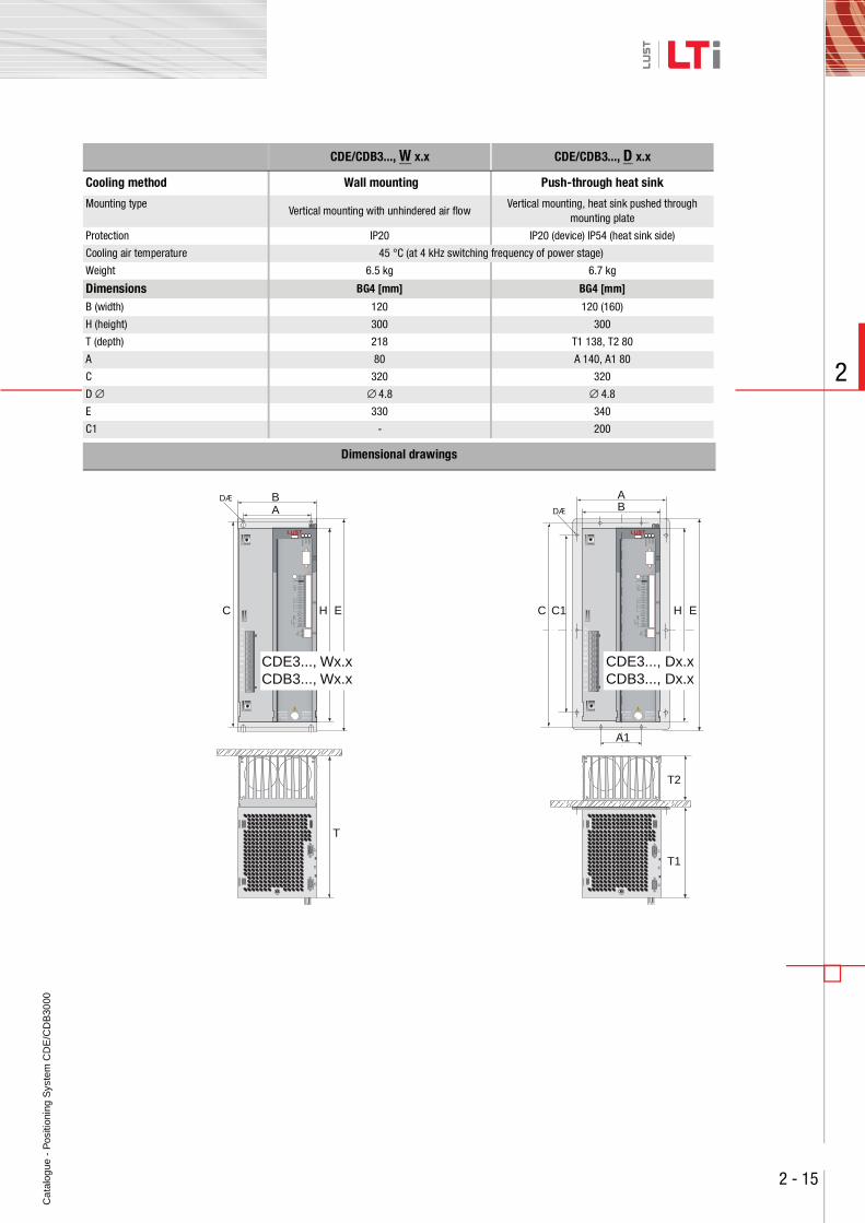
,CDE/CDB3..., W x.x ,CDE/CDB3..., D x.x
Cooling method Wall mounting Push-through heat sink
Mounting typeVertical mounting with unhindered air flow
Vertical mounting, heat sink pushed through mounting plate
Protection IP20 IP20 (device) IP54 (heat sink side)
Cooling air temperature 45 °C (at 4 kHz switching frequency of power stage)
Weight 6.5 kg 6.7 kg
Dimensions BG4 [mm] BG4 [mm]
B (width) 120 120 (160)
H (height) 300 300
T (depth) 218 T1 138, T2 80
A 80 A 140, A1 80
C 320 320
D ∅ ∅ 4.8 ∅ 4.8
E 330 340
C1 - 200
Dimensional drawings
BA
HC E
T
DÆ
X1
L3
U
V
W
RB+
RB
L-
L1
L2
E
B
A1
A
HC1C
T1
T2
DÆ
X1
L3
U
V
W
RB+
RB
L-
L1
L2
X5
X6
X7
X5
X6
X7
WARNINGCapacitor dischargetime > 3 min.Pay attention to theoperation manual!
ACHTUNGKondensatorent-ladezeit > 3 Min.Betriebsanleitung
beachten!
,5
WARNINGCapacitor dischargetime > 3 min.Pay attention to theoperation manual!
ACHTUNGKondensatorent-ladezeit > 3 Min.Betriebsanleitung
beachten!
,5
CDE3..., Wx.xCDB3..., Wx.x
CDE3..., Dx.xCDB3..., Dx.x
Ca
talo
gue
- P
ositi
onin
g S
yste
m C
DE
/CD
B30
00
2 - 16
2
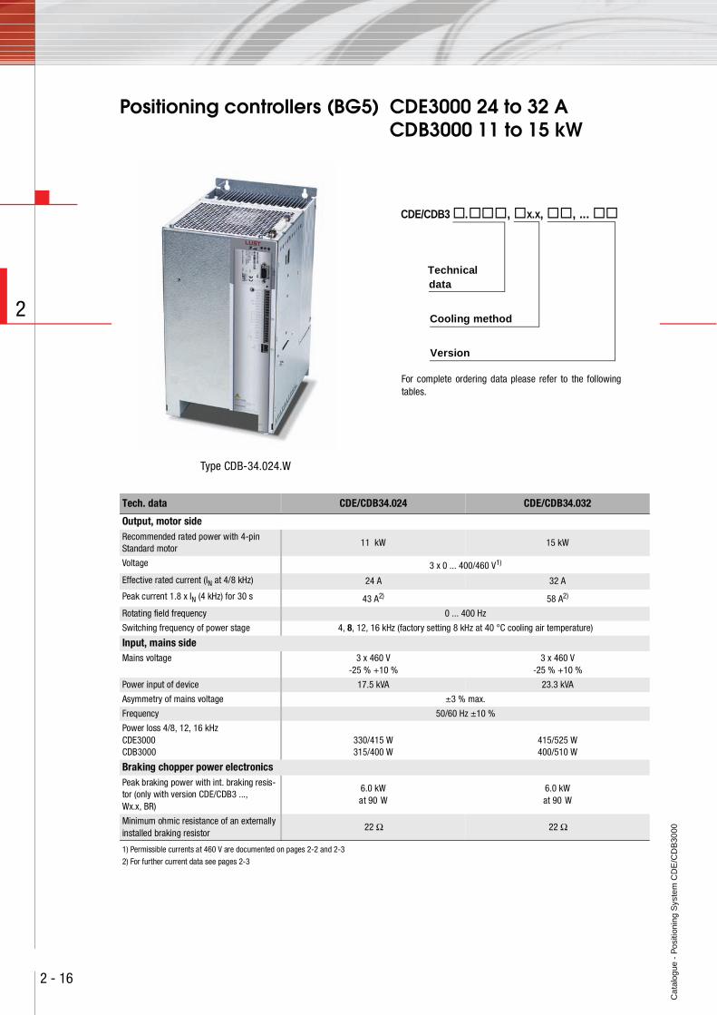
Positioning controllers (BG5) CDE3000 24 to 32 ACDB3000 11 to 15 kW
Type CDB-34.024.W
Tech. data CDE/CDB34.024 CDE/CDB34.032
Output, motor sideRecommended rated power with 4-pin Standard motor
11 kW 15 kW
Voltage 3 x 0 ... 400/460 V1)
Effective rated current (IN at 4/8 kHz) 24 A 32 A
Peak current 1.8 x IN (4 kHz) for 30 s 43 A2) 58 A2)
Rotating field frequency 0 ... 400 Hz
Switching frequency of power stage 4, 8, 12, 16 kHz (factory setting 8 kHz at 40 °C cooling air temperature)
Input, mains sideMains voltage 3 x 460 V
-25 % +10 %3 x 460 V
-25 % +10 %
Power input of device 17.5 kVA 23.3 kVA
Asymmetry of mains voltage ±3 % max.
Frequency 50/60 Hz ±10 %
Power loss 4/8, 12, 16 kHzCDE3000CDB3000
330/415 W315/400 W
415/525 W400/510 W
Braking chopper power electronicsPeak braking power with int. braking resis-tor (only with version CDE/CDB3 ..., Wx.x, BR)
6.0 kWat 90 W
6.0 kWat 90 W
Minimum ohmic resistance of an externally installed braking resistor
22 Ω 22 Ω
1) Permissible currents at 460 V are documented on pages 2-2 and 2-3
2) For further current data see pages 2-3
CDE/CDB3 . , x.x, , ...
Cooling method
Version
Technicaldata
For complete ordering data please refer to the followingtables.
Ca
talo
gue
- P
ositi
onin
g S
yste
m C
DE
/CD
B30
00
2 - 17
2
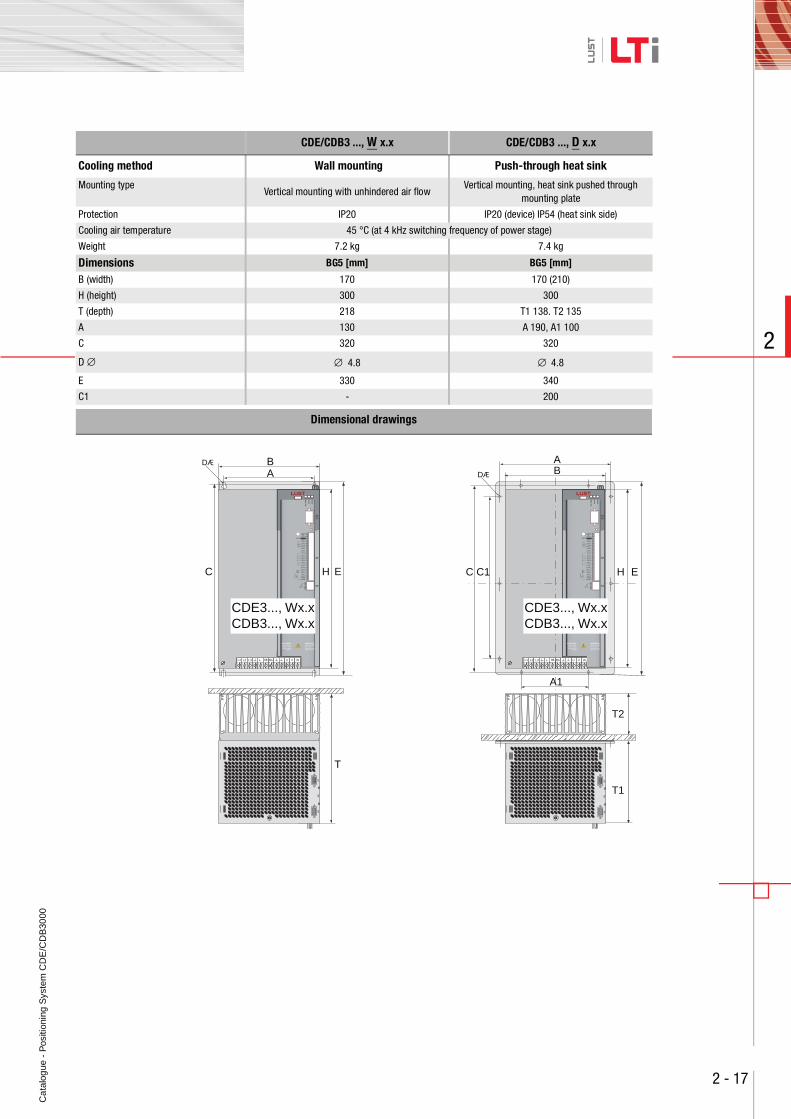
,CDE/CDB3 ..., W x.x ,CDE/CDB3 ..., D x.x
Cooling method Wall mounting Push-through heat sink
Mounting typeVertical mounting with unhindered air flow
Vertical mounting, heat sink pushed through mounting plate
Protection IP20 IP20 (device) IP54 (heat sink side)
Cooling air temperature 45 °C (at 4 kHz switching frequency of power stage)
Weight 7.2 kg 7.4 kg
Dimensions BG5 [mm] BG5 [mm]
B (width) 170 170 (210)
H (height) 300 300
T (depth) 218 T1 138. T2 135
A 130 A 190, A1 100
C 320 320
D ∅ ∅ 4.8 ∅ 4.8
E 330 340
C1 - 200
Dimensional drawings
L-L2 RB+RBL1 L3 U V W
B
A1
A
H EC1C
T1
T2
DÆ
L-L2 RB+RBL1 L3 U V W
X3
T
E
BA
HC
DÆ
X5
X6
X7
X5
X6
X7
WARNINGCapacitor dischargetime > 3 min.Pay attention to theoperation manual!
ACHTUNGKondensatorent-ladezeit > 3 Min.Betriebsanleitung
beachten!
,5
WARNINGCapacitor dischargetime > 3 min.Pay attention to theoperation manual!
ACHTUNGKondensatorent-ladezeit > 3 Min.Betriebsanleitung
beachten!
,5
CDE3..., Wx.xCDB3..., Wx.x
CDE3..., Wx.xCDB3..., Wx.x
Ca
talo
gue
- P
ositi
onin
g S
yste
m C
DE
/CD
B30
00
2 - 18
2
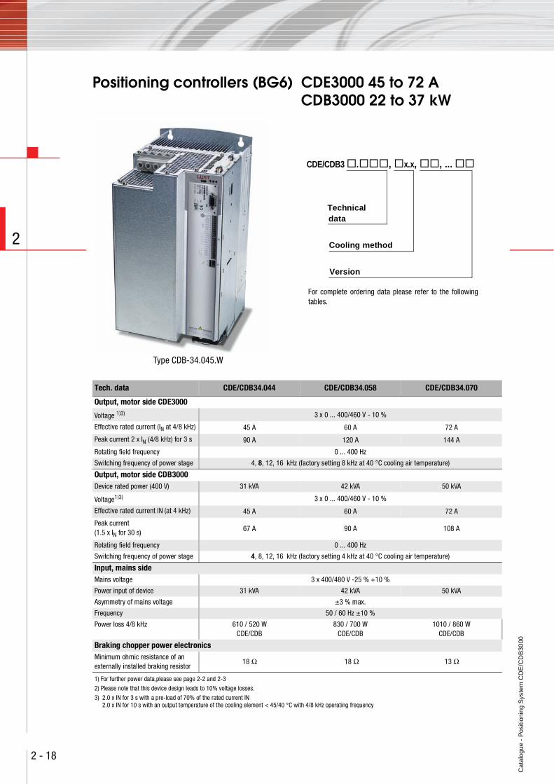
Positioning controllers (BG6) CDE3000 45 to 72 ACDB3000 22 to 37 kW
Type CDB-34.045.W
CDE/CDB3 . , x.x, , ...
Cooling method
Version
Technicaldata
For complete ordering data please refer to the followingtables.
Tech. data CDE/CDB34.044 CDE/CDB34.058 CDE/CDB34.070
Output, motor side CDE3000
Voltage 1)3) 3 x 0 ... 400/460 V - 10 %
Effective rated current (IN at 4/8 kHz) 45 A 60 A 72 A
Peak current 2 x IN (4/8 kHz) for 3 s 90 A 120 A 144 A
Rotating field frequency 0 ... 400 Hz
Switching frequency of power stage 4, 8, 12, 16 kHz (factory setting 8 kHz at 40 °C cooling air temperature)
Output, motor side CDB3000Device rated power (400 V) 31 kVA 42 kVA 50 kVA
Voltage1)3) 3 x 0 ... 400/460 V - 10 %
Effective rated current IN (at 4 kHz) 45 A 60 A 72 A
Peak current (1.5 x IN for 30 s) 67 A 90 A 108 A
Rotating field frequency 0 ... 400 Hz
Switching frequency of power stage 4, 8, 12, 16 kHz (factory setting 4 kHz at 40 °C cooling air temperature)
Input, mains sideMains voltage 3 x 400/480 V -25 % +10 %
Power input of device 31 kVA 42 kVA 50 kVA
Asymmetry of mains voltage ±3 % max.
Frequency 50 / 60 Hz ±10 %
Power loss 4/8 kHz 610 / 520 WCDE/CDB
830 / 700 WCDE/CDB
1010 / 860 WCDE/CDB
Braking chopper power electronicsMinimum ohmic resistance of an externally installed braking resistor
18 Ω 18 Ω 13 Ω
1) For further power data,please see page 2-2 and 2-3
2) Please note that this device design leads to 10% voltage losses.
3) 2.0 x IN for 3 s with a pre-load of 70% of the rated current IN2.0 x IN for 10 s with an output temperature of the cooling element < 45/40 °C with 4/8 kHz operating frequency
Ca
talo
gue
- P
ositi
onin
g S
yste
m C
DE
/CD
B30
00
2 - 19
2
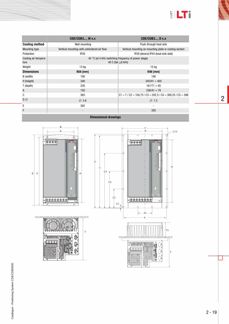
CDE/CDB3..., W x.x CDE/CDB3..., D x.x
Cooling method Wall mounting Push-through heat sink
Mounting type Vertical mounting with unhindered air flow Vertical mounting on mounting plate or cooling section
Protection IP20 IP20 (device) IP54 (heat sink side)
Cooling air tempera-ture
45 °C (at 4 kHz switching frequency of power stage)40 C (bei >8 kHz)
Weight 13 kg 15 kg
Dimensions BG6 [mm] BG6 [mm]
B (width) 190 190
H (height) 348 345/H1 = 405
T (depth) 230 161/T1 = 85
A 150 236/A1 = 78
C 365 C1 = 7 / C2 = 104,75 / C3 = 202,5 / C4 = 300,25 / C5 = 398
D ∅ ∅ 5.6 ∅ 7.5
E 382 -
F - 350
Dimensional drawings
WARNINGCapacitor dischargetime > 3 min.Pay attention to theoperation manual!
ACHTUNGKondensatorent-ladezeit > 3 Min.Betriebsanleitung
beachten!
+10,5V
OSD02
T
A
B
C HE
WARNINGCapacitor dischargetime > 3 min.Pay attention to theoperation manual!
ACHTUNGKondensatorent-ladezeit > 3 Min.Betriebsanleitung
beachten!
+10,5V
OSD02
T
T1
BF
E
C
C4
C3
C2
C1
A1
A
∅ D
H
Ca
talo
gue
- P
ositi
onin
g S
yste
m C
DE
/CD
B30
00
2 - 20
2
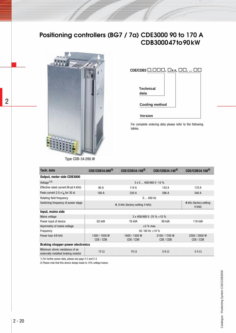
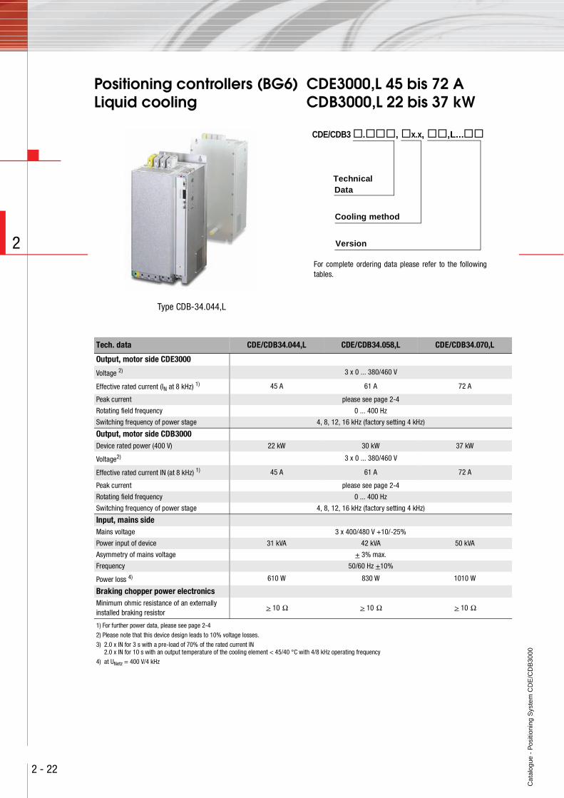
Positioning controllers (BG7 / 7a) CDE3000 90 to 170 A CDB3000 47 to 90 kW
Type CDB-34.090.W
Tech. data CDE/CDB34.0884) CDE/CDB34.1084) CDE/CDB34.1404) CDE/CDB34.1684)
Output, motor side CDB3000
Voltage1)3) 3 x 0 ... 400/460 V -10 %
Effective rated current IN (at 4 kHz) 90 A 110 A 143 A 170 A
Peak current 2.0 x IN for 30 s) 180 A 220 A 286 A 340 A
Rotating field frequency 0 ... 400 Hz
Switching frequency of power stage4, 8 kHz (factory setting 4 kHz)
4 kHz (factory setting4 kHz)
Input, mains sideMains voltage 3 x 400/480 V -25 % +10 %
Power input of device 62 kVA 76 kVA 99 kVA 118 kVA
Asymmetry of mains voltage ±3 % max.
Frequency 50 / 60 Hz ±10 %
Power loss 4/8 kHz 1300 / 1050 WCDE / CDB
1600 / 1300 WCDE / CDB
2100 / 1700 WCDE / CDB
2500 / 2000 WCDE / CDB
Braking chopper power electronicsMinimum ohmic resistance of an externally installed braking resistor
12 Ω 10 Ω 5.6 Ω 5.4 Ω
1) For further power data, please see page 2-2 and 2-3
2) Please note that this device design leads to 10% voltage losses.
CDE/CDB3 . , x.x, , ...
Cooling method
Version
Technicaldata
For complete ordering data please refer to the followingtables.
Ca
talo
gue
- P
ositi
onin
g S
yste
m C
DE
/CD
B30
00
2 - 21
2
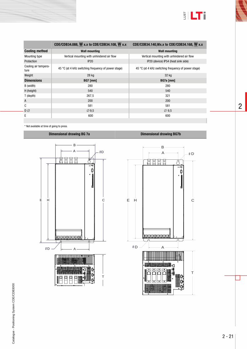
,CDE/CDB34.088, W x.x to CDE/CDB34.108, W x.x CDE/CDB34.140,Wx.x to ,CDE/CDB34.168, W x.x
Cooling method Wall mounting Wall mounting
Mounting type Vertical mounting with unhindered air flow Vertical mounting with unhindered air flow
Protection IP20 IP20 (device) IP54 (heat sink side)
Cooling air tempera-ture
45 °C (at 4 kHz switching frequency of power stage) 45 °C (at 4 kHz switching frequency of power stage)
Weight 28 kg 32 kg
Dimensions BG7 [mm] BG7a [mm]
B (width) 280 280
H (height) 540 540
T (depth) 267,5 321
A 200 200
C 581 581
D ∅ ∅ 9,5 ∅ 9,5
E 600 600
* Not available at time of going to press.
Dimensional drawing BG 7a Dimensional drawing BG7b
Ø
Ø
B
A D
CE H
D A
T
Ø
Ø
B
A D
CE H
AD
T
Ca
talo
gue
- P
ositi
onin
g S
yste
m C
DE
/CD
B30
00
2 - 22
2
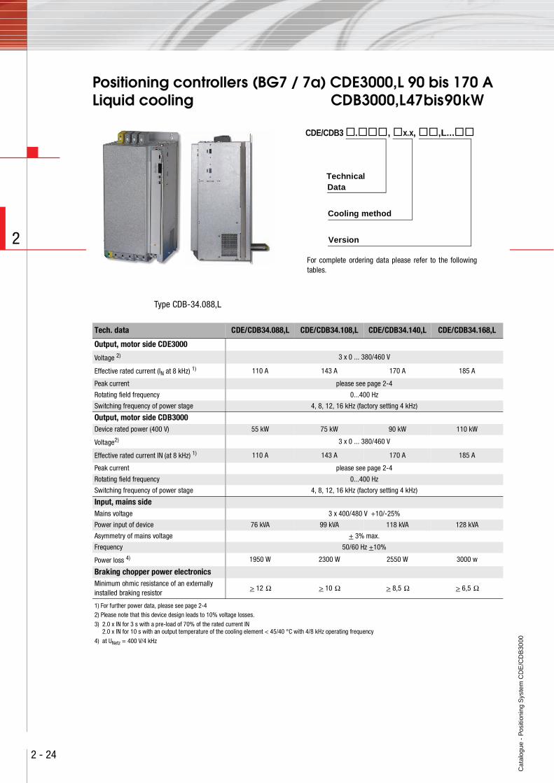
Positioning controllers (BG6) CDE3000,L 45 bis 72 ALiquid cooling CDB3000,L 22 bis 37 kW
Type CDB-34.044,L
CDE/CDB3 . , x.x, ,L...
Cooling method
Version
TechnicalData
For complete ordering data please refer to the followingtables.
Tech. data CDE/CDB34.044,L CDE/CDB34.058,L CDE/CDB34.070,L
Output, motor side CDE3000
Voltage 2) 3 x 0 ... 380/460 V
Effective rated current (IN at 8 kHz) 1) 45 A 61 A 72 A
Peak current please see page 2-4
Rotating field frequency 0 ... 400 Hz
Switching frequency of power stage 4, 8, 12, 16 kHz (factory setting 4 kHz)
Output, motor side CDB3000Device rated power (400 V) 22 kW 30 kW 37 kW
Voltage2) 3 x 0 ... 380/460 V
Effective rated current IN (at 8 kHz) 1) 45 A 61 A 72 A
Peak current please see page 2-4
Rotating field frequency 0 ... 400 Hz
Switching frequency of power stage 4, 8, 12, 16 kHz (factory setting 4 kHz)
Input, mains sideMains voltage 3 x 400/480 V +10/-25%
Power input of device 31 kVA 42 kVA 50 kVA
Asymmetry of mains voltage + 3% max.
Frequency 50/60 Hz +10%
Power loss 4) 610 W 830 W 1010 W
Braking chopper power electronicsMinimum ohmic resistance of an externally installed braking resistor
> 10 Ω > 10 Ω > 10 Ω
1) For further power data, please see page 2-4
2) Please note that this device design leads to 10% voltage losses.
3) 2.0 x IN for 3 s with a pre-load of 70% of the rated current IN2.0 x IN for 10 s with an output temperature of the cooling element < 45/40 °C with 4/8 kHz operating frequency
4) at UNetz = 400 V/4 kHz
Ca
talo
gue
- P
ositi
onin
g S
yste
m C
DE
/CD
B30
00
2 - 23
2
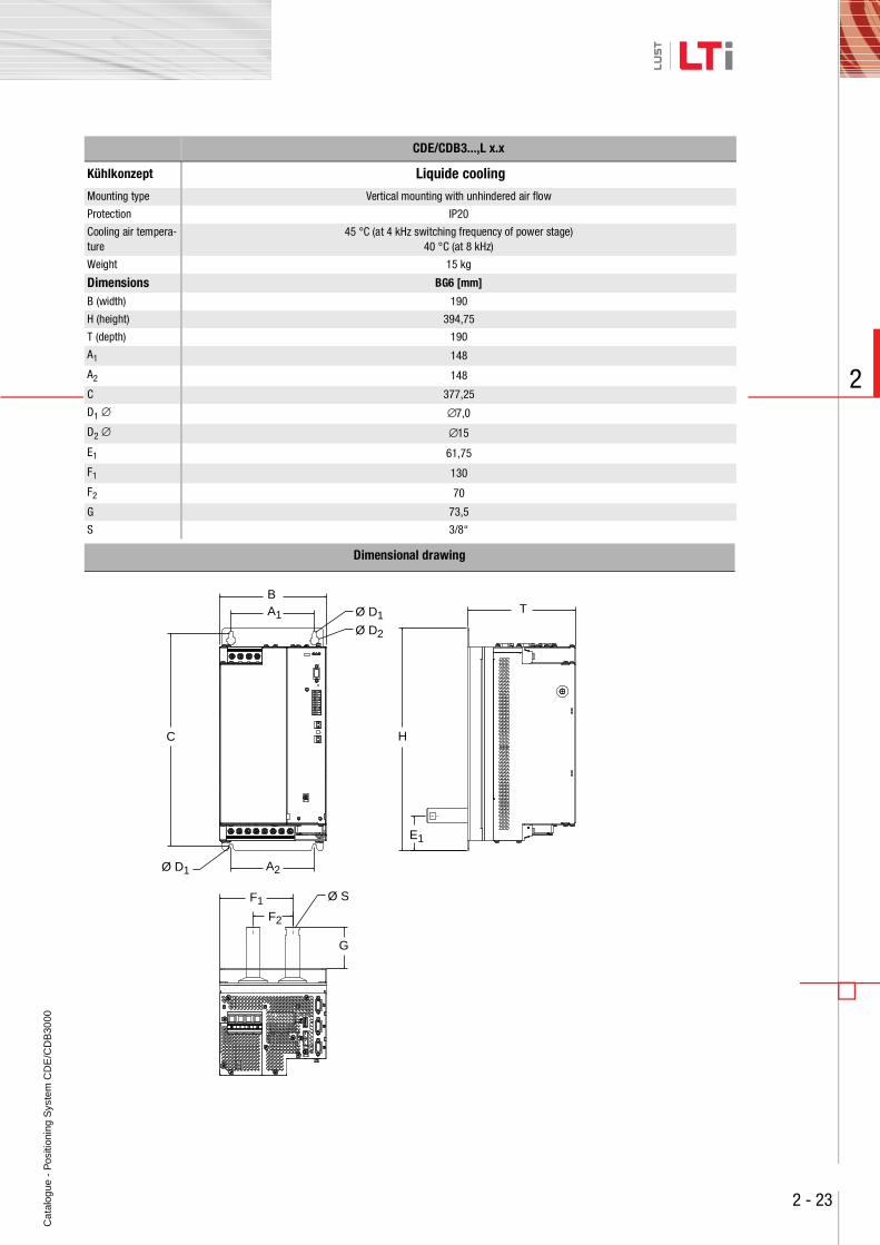
CDE/CDB3...,L x.x
Kühlkonzept Liquide cooling
Mounting type Vertical mounting with unhindered air flow
Protection IP20
Cooling air tempera-ture
45 °C (at 4 kHz switching frequency of power stage)40 °C (at 8 kHz)
Weight 15 kg
Dimensions BG6 [mm]
B (width) 190
H (height) 394,75
T (depth) 190
A1 148
A2 148
C 377,25
D1 ∅ ∅7,0
D2 ∅ ∅15
E1 61,75
F1 130
F2 70
G 73,5
S 3/8“
Dimensional drawing
E1
H
T
F1
F2
G
Ø D1
Ø D1
Ø S
Ø D2
C
A1
B
A2
Ca
talo
gue
- P
ositi
onin
g S
yste
m C
DE
/CD
B30
00
2 - 24
2
Positioning controllers (BG7 / 7a) CDE3000,L 90 bis 170 A Liquid cooling CDB3000,L 47 bis 90 kW
Type CDB-34.088,L
Tech. data CDE/CDB34.088,L CDE/CDB34.108,L CDE/CDB34.140,L CDE/CDB34.168,L
Output, motor side CDE3000
Voltage 2) 3 x 0 ... 380/460 V
Effective rated current (IN at 8 kHz) 1) 110 A 143 A 170 A 185 A
Peak current please see page 2-4
Rotating field frequency 0...400 Hz
Switching frequency of power stage 4, 8, 12, 16 kHz (factory setting 4 kHz)
Output, motor side CDB3000Device rated power (400 V) 55 kW 75 kW 90 kW 110 kW
Voltage2) 3 x 0 ... 380/460 V
Effective rated current IN (at 8 kHz) 1) 110 A 143 A 170 A 185 A
Peak current please see page 2-4
Rotating field frequency 0...400 Hz
Switching frequency of power stage 4, 8, 12, 16 kHz (factory setting 4 kHz)
Input, mains sideMains voltage 3 x 400/480 V +10/-25%
Power input of device 76 kVA 99 kVA 118 kVA 128 kVA
Asymmetry of mains voltage + 3% max.
Frequency 50/60 Hz +10%
Power loss 4) 1950 W 2300 W 2550 W 3000 w
Braking chopper power electronicsMinimum ohmic resistance of an externally installed braking resistor
> 12 Ω > 10 Ω > 8,5 Ω > 6,5 Ω
1) For further power data, please see page 2-4 2) Please note that this device design leads to 10% voltage losses.
3) 2.0 x IN for 3 s with a pre-load of 70% of the rated current IN2.0 x IN for 10 s with an output temperature of the cooling element < 45/40 °C with 4/8 kHz operating frequency
4) at UNetz = 400 V/4 kHz
CDE/CDB3 . , x.x, ,L...
Cooling method
Version
TechnicalData
For complete ordering data please refer to the followingtables.
Ca
talo
gue
- P
ositi
onin
g S
yste
m C
DE
/CD
B30
00
2 - 25
2
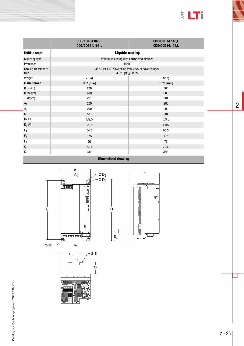
CDE/CDB34.088,LCDE/CDB34.108,L
CDE/CDB34.140,LCDE/CDB34.168,L
Kühlkonzept Liquide cooling
Mounting type Vertical mounting with unhindered air flow
Protection IP20
Cooling air tempera-ture
45 °C (at 4 kHz switching frequency of power stage)40 °C (at >8 kHz)
Weight 28 kg 32 kg
Dimensions BG7 [mm] BG7a [mm]
B (width) 280 280
H (height) 600 600
T (depth) 201 281
A1 200 200
A2 200 200
C 581 581
D1 ∅ ∅9,5 ∅9,5
D2 ∅ ∅15 ∅15
E1 66,5 66,5
F1 175 175
F2 70 70
G 73,5 73,5
S 3/8“ 3/8“
Dimensional drawing
E1
H
T
F1
F2
G
Ø D1
Ø D1
Ø S
Ø D2
C
A1
B
A2
Ca
talo
gue
- P
ositi
onin
g S
yste
m C
DE
/CD
B30
00
2 - 26
2
Notes:
Ca
talo
gue
- P
ositi
onin
g S
yste
m C
DE
/CD
B30
00
3 - 1
3
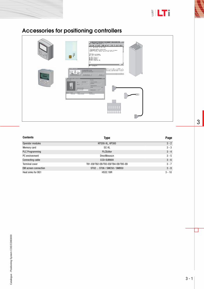
Accessories for positioning controllers
Contents Type Page
Operator modules KP200-XL, KP300 3 - 2
Memory card SC-XL 3 - 3
PLC Programming PLCEditor 3 - 4
PC environment DRIVEMANAGER 3 - 5
Connecting cable CCD-SUB90X 3 - 6
Terminal cover TB1-EB/TB2-EB/TB3-EB/TB4-EB/TB5-EB 3 - 7
EM screen connection ST02 ... ST06 / SMC50 / SMB50 3 - 8
Heat sinks for BG1 HS32.1BR 3 - 10
Ca
talo
gue
- P
ositi
onin
g S
yste
m C
DE
/CD
B30
00
3 - 2
3
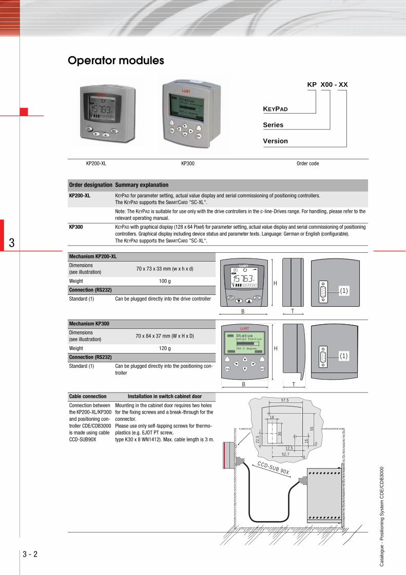
Operator modules
KP200-XL KP300 Order code
KEYPAD
Series
KP X00 - XX
Version
Order designation Summary explanation
KP200-XL KEYPAD for parameter setting, actual value display and serial commissioning of positioning controllers. The KEYPAD supports the SMARTCARD "SC-XL".
Note: The KEYPAD is suitable for use only with the drive controllers in the c-line-Drives range. For handling, please refer to the relevant operating manual.
KP300 KEYPAD with graphical display (128 x 64 Pixel) for parameter setting, actual value display and serial commissioning of positioning controllers. Graphical display including device status and parameter texts. Language: German or English (configurable).The KEYPAD supports the SMARTCARD "SC-XL".
Mechanism KP200-XL
Dimensions (see illustration)
70 x 73 x 33 mm (w x h x d)
Weight 100 g
Connection (RS232)
Standard (1) Can be plugged directly into the drive controller
Mechanism KP300
Dimensions (see illustration)
70 x 84 x 37 mm (W x H x D)
Weight 120 g
Connection (RS232)
Standard (1) Can be plugged directly into the positioning con-troller
Cable connection Installation in switch cabinet door
Connection between the KP200-XL/KP300 and positioning con-troller CDE/CDB3000 is made using cable CCD-SUB90X
Mounting in the cabinet door requires two holes for the fixing screws and a break-through for the connector.Please use only self-tapping screws for thermo-plastics (e.g. EJOT PT screw, type K30 x 8 WN1412). Max. cable length is 3 m.
H
TB
(1)startenter
stopreturn
VAL
Hz
H
TB
(1)
Status
360.0 degree
Actual Position
Back Help
stop start
57,5
52,7
1522,5
55
18
35
12,5
0
0
CCD-SUB 90X
Ca
talo
gue
- P
ositi
onin
g S
yste
m C
DE
/CD
B30
00
3 - 3
3
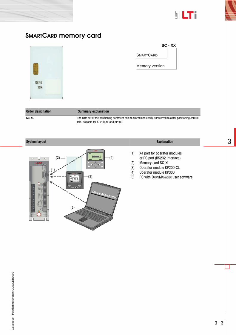
SMARTCARD memory card
Order designation Summary explanation
SC-XL The data set of the positioning controller can be stored and easily transferred to other positioning control-lers. Suitable for KP200-XL and KP300.
System layout Explanation
(1) X4 port for operator modules or PC port (RS232 interface)
(2) Memory card SC-XL(3) Operator module KP200-XL(4) Operator module KP300(5) PC with DRIVEMANAGER user software
SC - XX
SMARTCARD
Memory version
(1)
(2)
(3)
(4)
(5)
startenter
stopreturn
VAL
Hz
Ca
talo
gue
- P
ositi
onin
g S
yste
m C
DE
/CD
B30
00
3 - 4
3
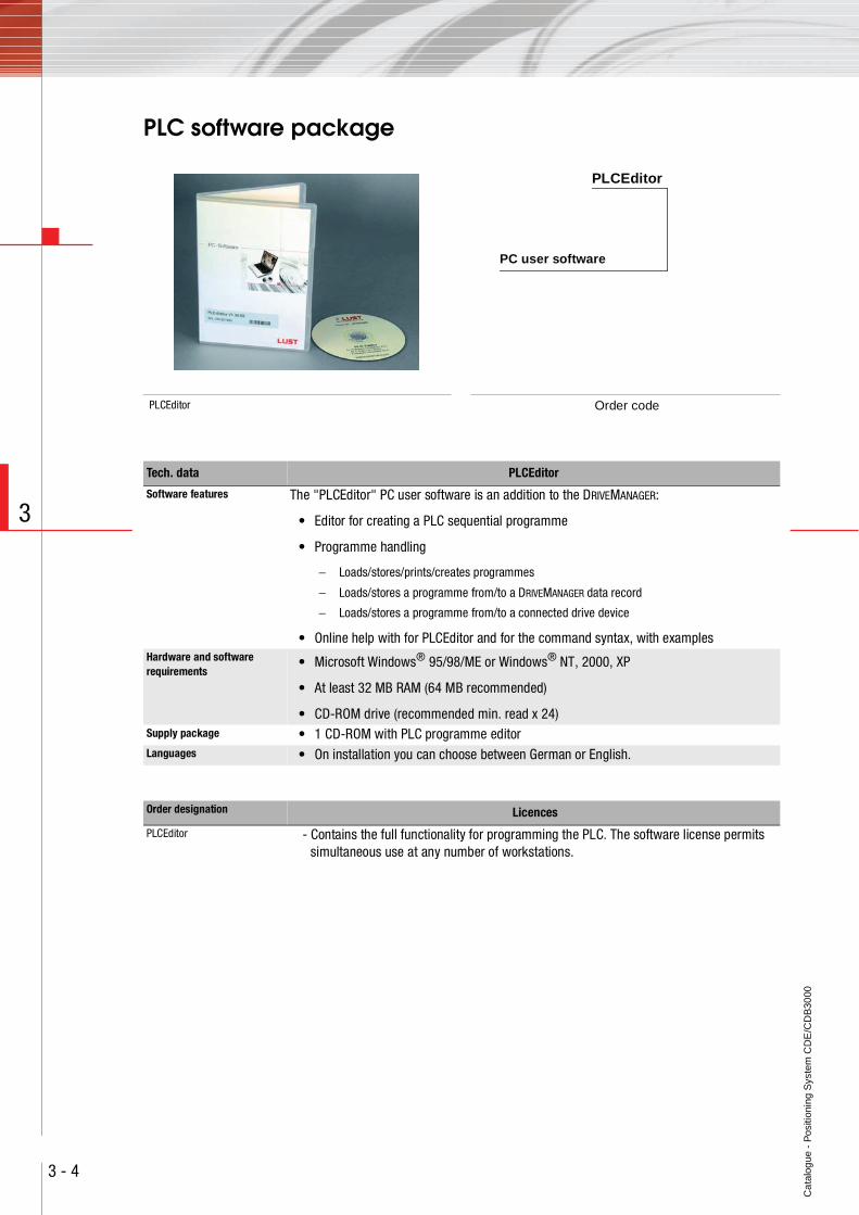
PLC software package
PLCEditor Order code
PLCEditor
PC user software
Tech. data PLCEditor
Software features The "PLCEditor" PC user software is an addition to the DRIVEMANAGER:
• Editor for creating a PLC sequential programme
• Programme handling
− Loads/stores/prints/creates programmes
− Loads/stores a programme from/to a DRIVEMANAGER data record
− Loads/stores a programme from/to a connected drive device
• Online help with for PLCEditor and for the command syntax, with examples Hardware and software requirements
• Microsoft Windows® 95/98/ME or Windows® NT, 2000, XP
• At least 32 MB RAM (64 MB recommended)
• CD-ROM drive (recommended min. read x 24)Supply package • 1 CD-ROM with PLC programme editorLanguages • On installation you can choose between German or English.
Order designation Licences
PLCEditor - Contains the full functionality for programming the PLC. The software license permits simultaneous use at any number of workstations.
Ca
talo
gue
- P
ositi
onin
g S
yste
m C
DE
/CD
B30
00
3 - 5
3
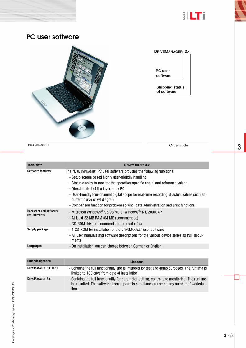
PC user software
DRIVEMANAGER 3.x Order code
Tech. data DRIVEMANAGER 3.x
Software features The "DRIVEMANAGER" PC user software provides the following functions:
- Setup screen based highly user-friendly handling- Status display to monitor the operation-specific actual and reference values- Direct control of the inverter by PC
- User-friendly four-channel digital scope for real-time recording of actual values such as current curve or v/t diagram
- Comparison function for problem solving, data administration and print functionsHardware and software requirements
- Microsoft Windows® 95/98/ME or Windows® NT, 2000, XP
- At least 32 MB RAM (64 MB recommended)- CD-ROM drive (recommended min. read x 24)
Supply package - 1 CD-ROM for installation of the DRIVEMANAGER user software
- All user manuals and software descriptions for the various device series as PDF docu-ments
Languages - On installation you can choose between German or English.
Order designation Licences
DRIVEMANAGER 3.x TEST - Contains the full functionality and is intended for test and demo purposes. The runtime is limited to 180 days from date of installation.
DRIVEMANAGER 3.x - Contains the full functionality for parameter-setting, control and monitoring. The runtime is unlimited. The software license permits simultaneous use on any number of worksta-tions.
DRIVEMANAGER 3.x
Shipping status
PC usersoftware
of software
Ca
talo
gue
- P
ositi
onin
g S
yste
m C
DE
/CD
B30
00
3 - 6
3
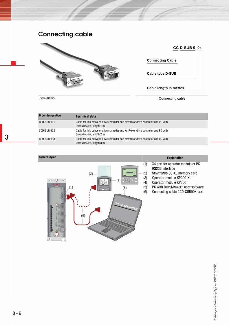
Connecting cable
CCD-SUB 90x Connecting cable
CC D-SUB 9 0X
Cable length in metres
Cable type D-SUB
Connecting Cable
Order designation Technical data
CCD-SUB 901 Cable for link between drive controller and KEYPAD or drive controller and PC with DRIVEMANAGER, length 1 m
CCD-SUB 902 Cable for link between drive controller and KEYPAD or drive controller and PC with DRIVEMANAGER, length 2 m
CCD-SUB 903 Cable for link between drive controller and KEYPAD or drive controller and PC with DRIVEMANAGER, length 3 m
System layout Explanation
(1) X4 port for operator module or PC RS232 interface
(2) SMARTCARD SC-XL memory card(3) Operator module KP200-XL(4) Operator module KP300(5) PC with DRIVEMANAGER user software(6) Connecting cable CCD-SUB90X, x.x
(1)
(2)
(6)
(3)
(5)startenter
stopreturn
VAL
Hz
Ca
talo
gue
- P
ositi
onin
g S
yste
m C
DE
/CD
B30
00
3 - 7
3
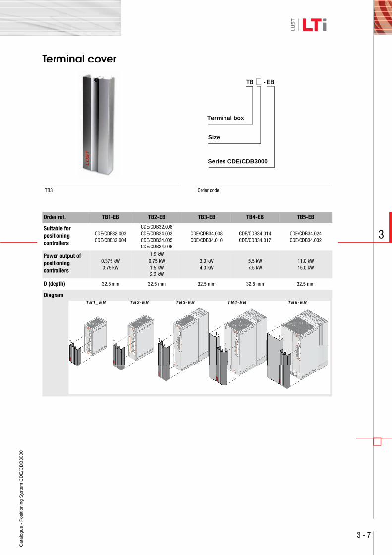
Terminal cover
TB3 Order code
Order ref. TB1-EB TB2-EB TB3-EB TB4-EB TB5-EB
Suitable for positioning controllers
CDE/CDB32.003CDE/CDB32.004
CDE/CDB32.008CDE/CDB34.003CDE/CDB34.005CDE/CDB34.006
CDE/CDB34.008CDE/CDB34.010
CDE/CDB34.014CDE/CDB34.017
CDE/CDB34.024CDE/CDB34.032
Power output of positioning controllers
0.375 kW0.75 kW
1.5 kW0.75 kW1.5 kW2.2 kW
3.0 kW4.0 kW
5.5 kW7.5 kW
11.0 kW15.0 kW
D (depth) 32.5 mm 32.5 mm 32.5 mm 32.5 mm 32.5 mm
Diagram
TB - EB
Size
Terminal box
Series CDE/CDB3000
Ca
talo
gue
- P
ositi
onin
g S
yste
m C
DE
/CD
B30
00
3 - 8
3
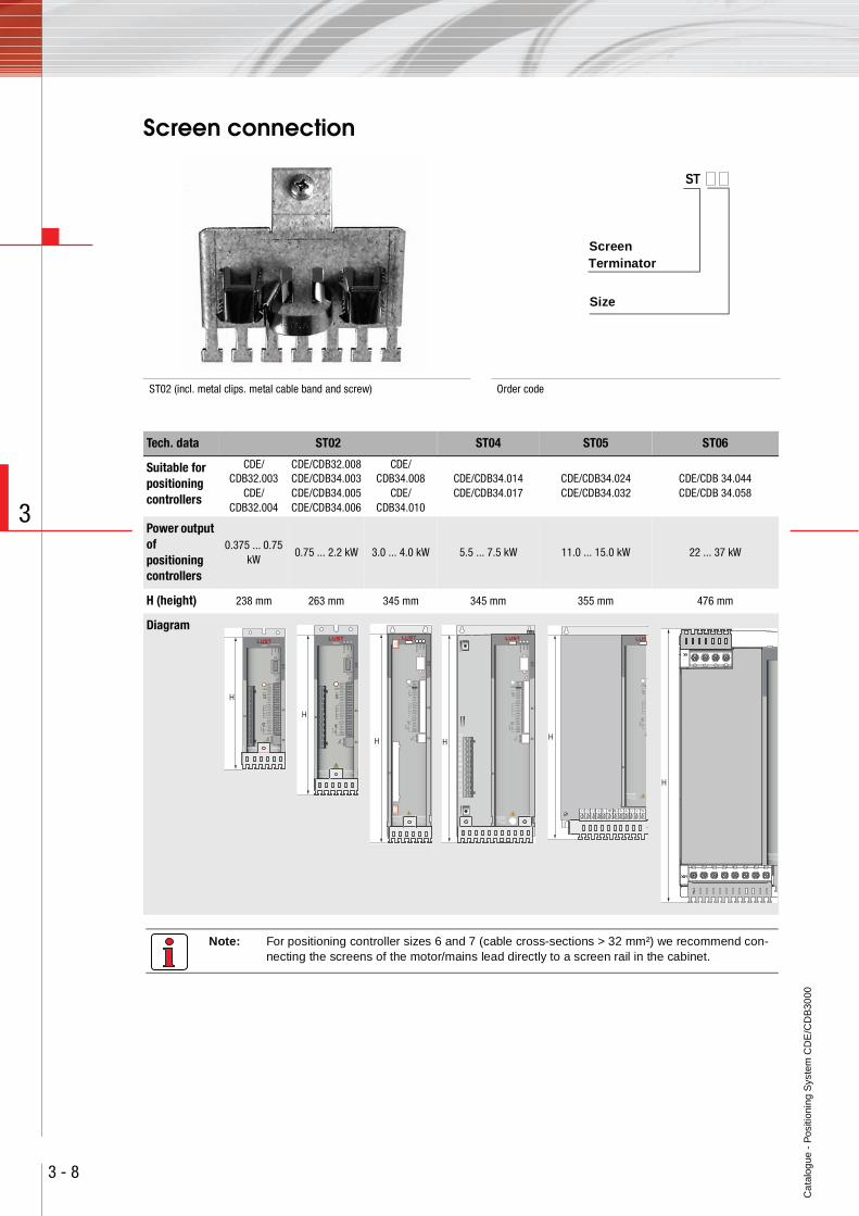
Screen connection
Note: For positioning controller sizes 6 and 7 (cable cross-sections > 32 mm²) we recommend con-necting the screens of the motor/mains lead directly to a screen rail in the cabinet.
ST02 (incl. metal clips. metal cable band and screw) Order code
ST
Size
Screen Terminator
Tech. data ST02 ST04 ST05 ST06
Suitable for positioning controllers
CDE/CDB32.003
CDE/CDB32.004
CDE/CDB32.008CDE/CDB34.003CDE/CDB34.005CDE/CDB34.006
CDE/CDB34.008
CDE/CDB34.010
CDE/CDB34.014CDE/CDB34.017
CDE/CDB34.024CDE/CDB34.032
CDE/CDB 34.044CDE/CDB 34.058
Power output of positioning controllers
0.375 ... 0.75 kW
0.75 ... 2.2 kW 3.0 ... 4.0 kW 5.5 ... 7.5 kW 11.0 ... 15.0 kW 22 ... 37 kW
H (height) 238 mm 263 mm 345 mm 345 mm 355 mm 476 mm
Diagram
H
H
WARNINGCapacitor dischargetime > 3 min.Pay attention to theoperation manual!
ACHTUNGKondensatorent-ladezeit > 3 Min.Betriebsanleitung
beachten!
Ω
,5
HX1
L3
U
V
W
RB+
RB
L-
L1
L2
WARNINGCapacitor dischargetime > 3 min.Pay attention to theoperation manual!
ACHTUNGKondensatorent-ladezeit > 3 Min.Betriebsanleitung
beachten!
Ω
,5
H
L-L2 RB+RBL1 L3 U V W
ACHTUNGKondensatorent-ladezeit > 3 Min.Betriebsanleitung
beachten!
Ω
H
H
ACHTUNGKondensatorent-ladezeit > 3 Min.Betriebsanleitung
beachten!
Ca
talo
gue
- P
ositi
onin
g S
yste
m C
DE
/CD
B30
00
3 - 9
3
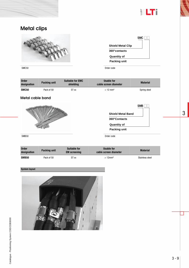
Metal clips
Metal cable band
SMC50 Order code
Order designation
Packing unitSuitable for EMC
shieldingUsable for
cable screen diameterMaterial
SMC50 Pack of 50 ST xx < 12 mm² Spring steel
SMB50 Order code
Order designation
Packing unitSuitable for
EM screeningUsable for
cable screen diameterMaterial
SMB50 Pack of 50 ST xx > 12mm² Stainless steel
System layout
SMC
Shield Metal Clip
Quantity of
360°contacts
Packing unit
SMB xx
Shield Metal Band
Quantity1)
SMB
Shield Metal Band
Quantity of
360°Contacts
Packing unit
Ca
talo
gue
- P
ositi
onin
g S
yste
m C
DE
/CD
B30
00
3 - 10
3
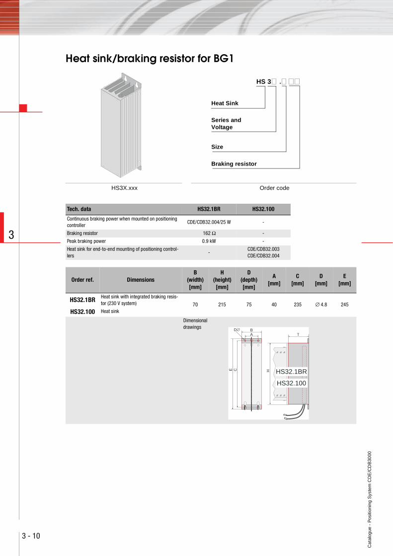
Heat sink/braking resistor for BG1
HS3X.xxx Order code
HS 3 .
Braking resistor
Size
Series and
Heat Sink
Voltage
Tech. data HS32.1BR HS32.100
Continuous braking power when mounted on positioning controller
CDE/CDB32.004/25 W -
Braking resistor 162 Ω -
Peak braking power 0.9 kW -
Heat sink for end-to-end mounting of positioning control-lers
-CDE/CDB32.003 CDE/CDB32.004
Order ref. DimensionsB
(width)[mm]
H (height)[mm]
D (depth)[mm]
A[mm]
C[mm]
D[mm]
E[mm]
HS32.1BR Heat sink with integrated braking resis-tor (230 V system) 70 215 75 40 235 ∅ 4.8 245
HS32.100 Heat sink
Dimensional drawings
T
H
BA
C HS32.1BR
HS32.100
E
D∅
Ca
talo
gue
- P
ositi
onin
g S
yste
m C
DE
/CD
B30
00
4 - 1
4
User and communication modules
Contents Type Page
User modules UM-8I4O 4 - 2
Communication modules CM-DPV1 4 - 3
12
34
516
1718
1920
1112
1314
156
78
910
ANTRIEBSTE
CHNIK
SN.:
000.000.00000000
Typ:
Netz:
Ausg.:
D-35633 Lahnau
12
ANTRIEBSTE
CHNIK
SN.:
000.000.00000000
Typ:
Netz:
Ausg.:
D-35633 Lahnau
Ca
talo
gue
- P
ositi
onin
g S
yste
m C
DE
/CD
B30
00
4 - 2
4
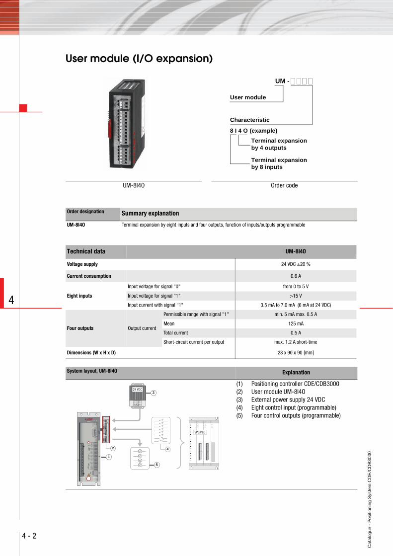
User module (I/O expansion)
UM-8I4O Order code
UM -
8 I 4 O (example)
Characteristic
User module
Terminal expansion
Terminal expansion
by 4 outputs
by 8 inputs
Order designation Summary explanation
UM-8I4O Terminal expansion by eight inputs and four outputs, function of inputs/outputs programmable
Technical data UM-8I4O
Voltage supply 24 VDC ±20 %
Current consumption 0.6 A
Eight inputs
Input voltage for signal "0" from 0 to 5 V
Input voltage for signal "1" >15 V
Input current with signal "1" 3.5 mA to 7.0 mA (6 mA at 24 VDC)
Four outputs Output current
Permissible range with signal "1" min. 5 mA max. 0.5 A
Mean 125 mA
Total current 0.5 A
Short-circuit current per output max. 1.2 A short-time
Dimensions (W x H x D) 28 x 90 x 90 [mm]
System layout, UM-8I4O Explanation
(1) Positioning controller CDE/CDB3000(2) User module UM-8I4O(3) External power supply 24 VDC(4) Eight control input (programmable)(5) Four control outputs (programmable)
34
56
78
910
1112
12
1314
1516
17
L-L1 L+N
24 VDC
1112
1314
1516
1718
1920
12
34
56
78
910
1112
1314
1516
1718
1920
12
34
56
78
910
SPS/PLC
1
3
5
2 4
Ca
talo
gue
- P
ositi
onin
g S
yste
m C
DE
/CD
B30
00
4 - 3
4
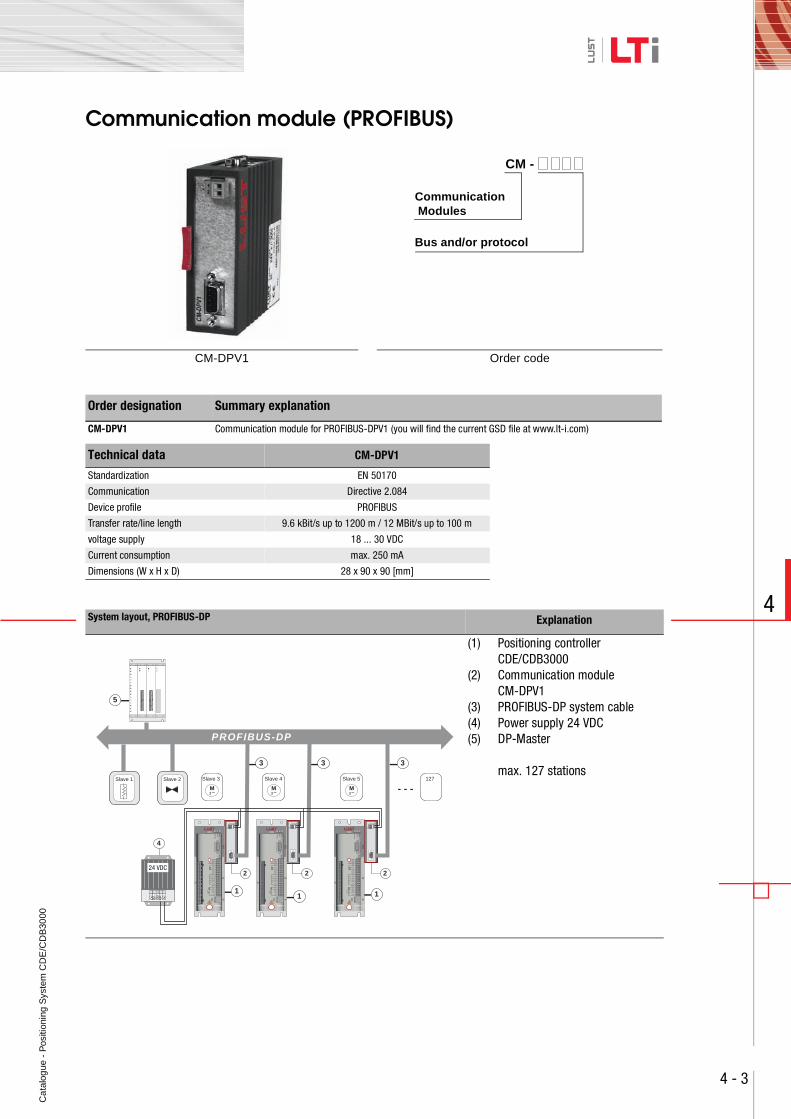
Communication module (PROFIBUS)
CM-DPV1 Order code
Order designation Summary explanation
CM-DPV1 Communication module for PROFIBUS-DPV1 (you will find the current GSD file at www.lt-i.com)
Technical data CM-DPV1
Standardization EN 50170
Communication Directive 2.084
Device profile PROFIBUS
Transfer rate/line length 9.6 kBit/s up to 1200 m / 12 MBit/s up to 100 m
voltage supply 18 ... 30 VDC
Current consumption max. 250 mA
Dimensions (W x H x D) 28 x 90 x 90 [mm]
System layout, PROFIBUS-DP Explanation
(1) Positioning controller CDE/CDB3000
(2) Communication module CM-DPV1
(3) PROFIBUS-DP system cable(4) Power supply 24 VDC(5) DP-Master
max. 127 stations
CM -
Bus and/or protocol
Communication Modules
PROFIBUS-DP
127
3 33
11 1
12
12
12
2 2 2
Slave 2Slave 1
- - -
4
L-L1 L+N
24 VDC
Slave 3
M3~
Slave 4
M3~
Slave 5
M3~
5 1112
1314
1516
1718
1920
12
34
56
78
910
1112
1314
1516
1718
1920
12
34
56
78
910
Ca
talo
gue
- P
ositi
onin
g S
yste
m C
DE
/CD
B30
00
4 - 4
4
Ca
talo
gue
- P
ositi
onin
g S
yste
m C
DE
/CD
B30
00
5 - 1
5
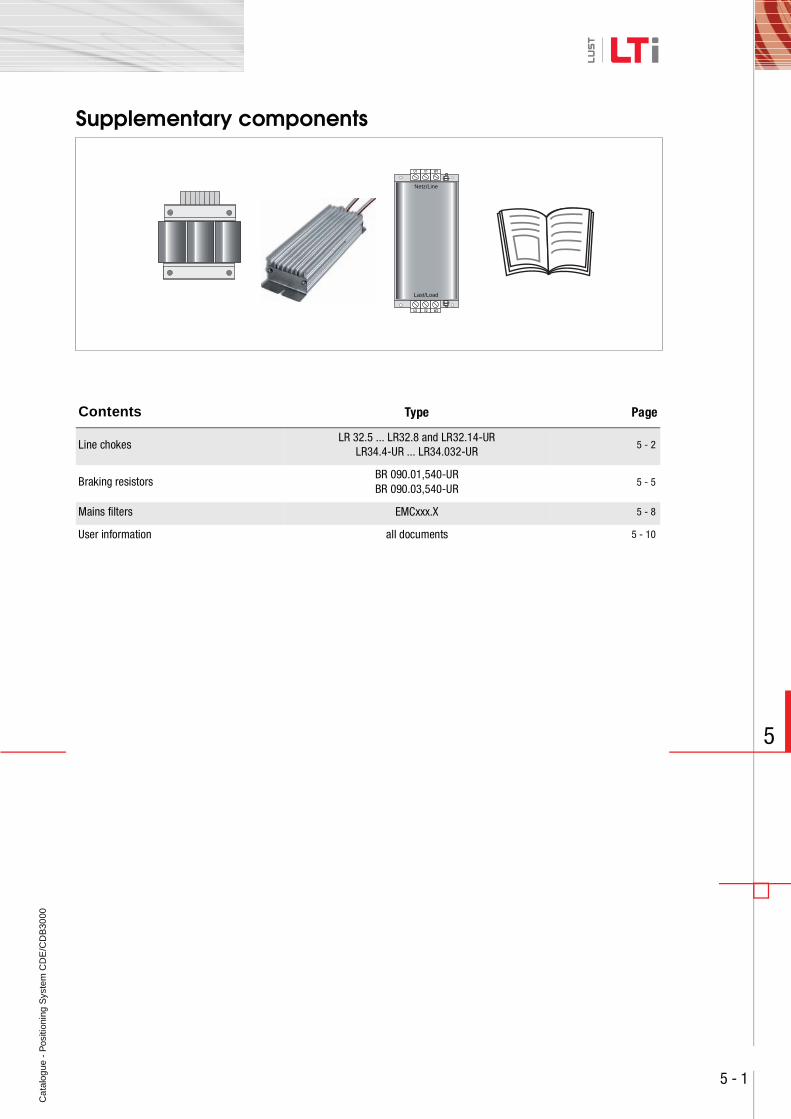
Supplementary components
Contents Type Page
Line chokesLR 32.5 ... LR32.8 and LR32.14-UR
LR34.4-UR ... LR34.032-UR5 - 2
Braking resistorsBR 090.01,540-URBR 090.03,540-UR
5 - 5
Mains filters EMCxxx.X 5 - 8
User information all documents 5 - 10
Netz/Line
Last/Load
U1 V1 W1
U2 V2 W2
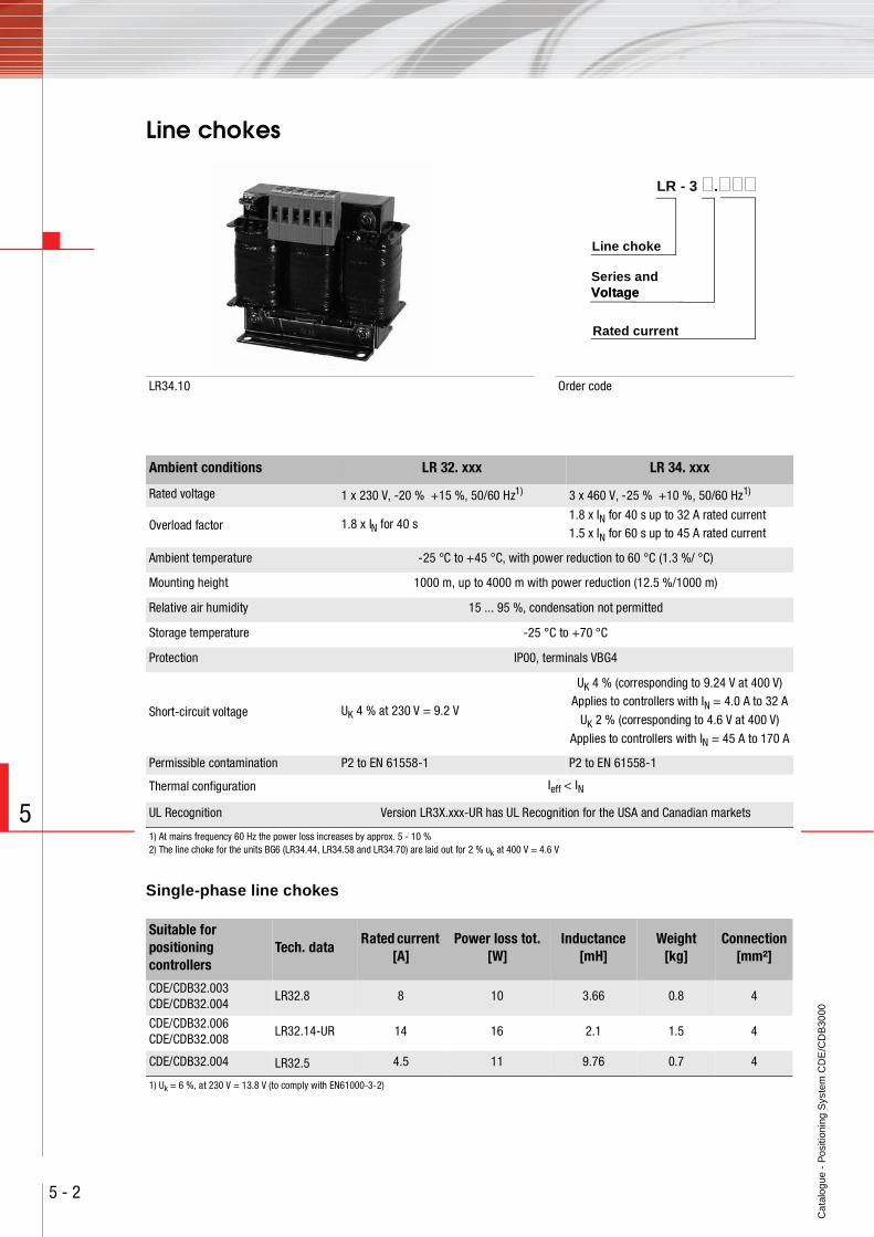
Ca
talo
gue
- P
ositi
onin
g S
yste
m C
DE
/CD
B30
00
5 - 2
5
Line chokes
Single-phase line chokes
LR34.10 Order code
Rated current
Series and
Line choke
VoltageVoltage
LR - 3 .
Ambient conditions LR 32. xxx LR 34. xxx
Rated voltage 1 x 230 V, -20 % +15 %, 50/60 Hz1) 3 x 460 V, -25 % +10 %, 50/60 Hz1)
Overload factor 1.8 x IN for 40 s1.8 x IN for 40 s up to 32 A rated current1.5 x IN for 60 s up to 45 A rated current
Ambient temperature -25 °C to +45 °C, with power reduction to 60 °C (1.3 %/ °C)
Mounting height 1000 m, up to 4000 m with power reduction (12.5 %/1000 m)
Relative air humidity 15 ... 95 %, condensation not permitted
Storage temperature -25 °C to +70 °C
Protection IP00, terminals VBG4
Short-circuit voltage UK 4 % at 230 V = 9.2 V
UK 4 % (corresponding to 9.24 V at 400 V)Applies to controllers with IN = 4.0 A to 32 A
UK 2 % (corresponding to 4.6 V at 400 V)
Applies to controllers with IN = 45 A to 170 A
Permissible contamination P2 to EN 61558-1 P2 to EN 61558-1
Thermal configuration Ieff < IN
UL Recognition Version LR3X.xxx-UR has UL Recognition for the USA and Canadian markets
1) At mains frequency 60 Hz the power loss increases by approx. 5 - 10 %2) The line choke for the units BG6 (LR34.44, LR34.58 and LR34.70) are laid out for 2 % uk at 400 V = 4.6 V
Suitable for positioning controllers
Tech. dataRated current
[A]Power loss tot.
[W]Inductance
[mH]Weight
[kg]Connection
[mm²]
CDE/CDB32.003CDE/CDB32.004
LR32.8 8 10 3.66 0.8 4
CDE/CDB32.006CDE/CDB32.008
LR32.14-UR 14 16 2.1 1.5 4
CDE/CDB32.004 LR32.5 4.5 11 9.76 0.7 4
1) Uk = 6 %, at 230 V = 13.8 V (to comply with EN61000-3-2)
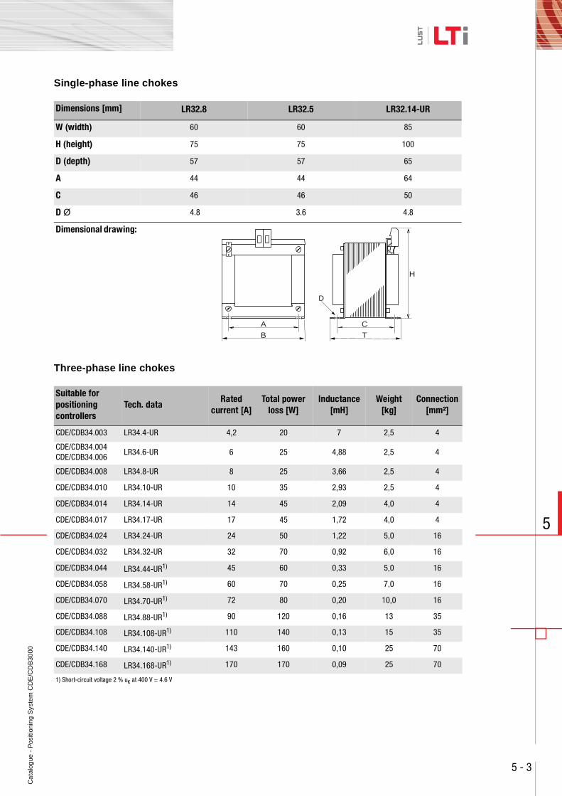
Ca
talo
gue
- P
ositi
onin
g S
yste
m C
DE
/CD
B30
00
5 - 3
5
Single-phase line chokes
Three-phase line chokes
Dimensions [mm] LR32.8 LR32.5 LR32.14-UR
W (width) 60 60 85
H (height) 75 75 100
D (depth) 57 57 65
A 44 44 64
C 46 46 50
D Ø 4.8 3.6 4.8
Dimensional drawing:
Suitable for positioning controllers
Tech. dataRated
current [A]Total power
loss [W]Inductance
[mH]Weight
[kg]Connection
[mm²]
CDE/CDB34.003 LR34.4-UR 4,2 20 7 2,5 4
CDE/CDB34.004CDE/CDB34.006
LR34.6-UR 6 25 4,88 2,5 4
CDE/CDB34.008 LR34.8-UR 8 25 3,66 2,5 4
CDE/CDB34.010 LR34.10-UR 10 35 2,93 2,5 4
CDE/CDB34.014 LR34.14-UR 14 45 2,09 4,0 4
CDE/CDB34.017 LR34.17-UR 17 45 1,72 4,0 4
CDE/CDB34.024 LR34.24-UR 24 50 1,22 5,0 16
CDE/CDB34.032 LR34.32-UR 32 70 0,92 6,0 16
CDE/CDB34.044 LR34.44-UR1) 45 60 0,33 5,0 16
CDE/CDB34.058 LR34.58-UR1) 60 70 0,25 7,0 16
CDE/CDB34.070 LR34.70-UR1) 72 80 0,20 10,0 16
CDE/CDB34.088 LR34.88-UR1) 90 120 0,16 13 35
CDE/CDB34.108 LR34.108-UR1) 110 140 0,13 15 35
CDE/CDB34.140 LR34.140-UR1) 143 160 0,10 25 70
CDE/CDB34.168 LR34.168-UR1) 170 170 0,09 25 70
1) Short-circuit voltage 2 % uK at 400 V = 4.6 V
A
B
C
H
T
D
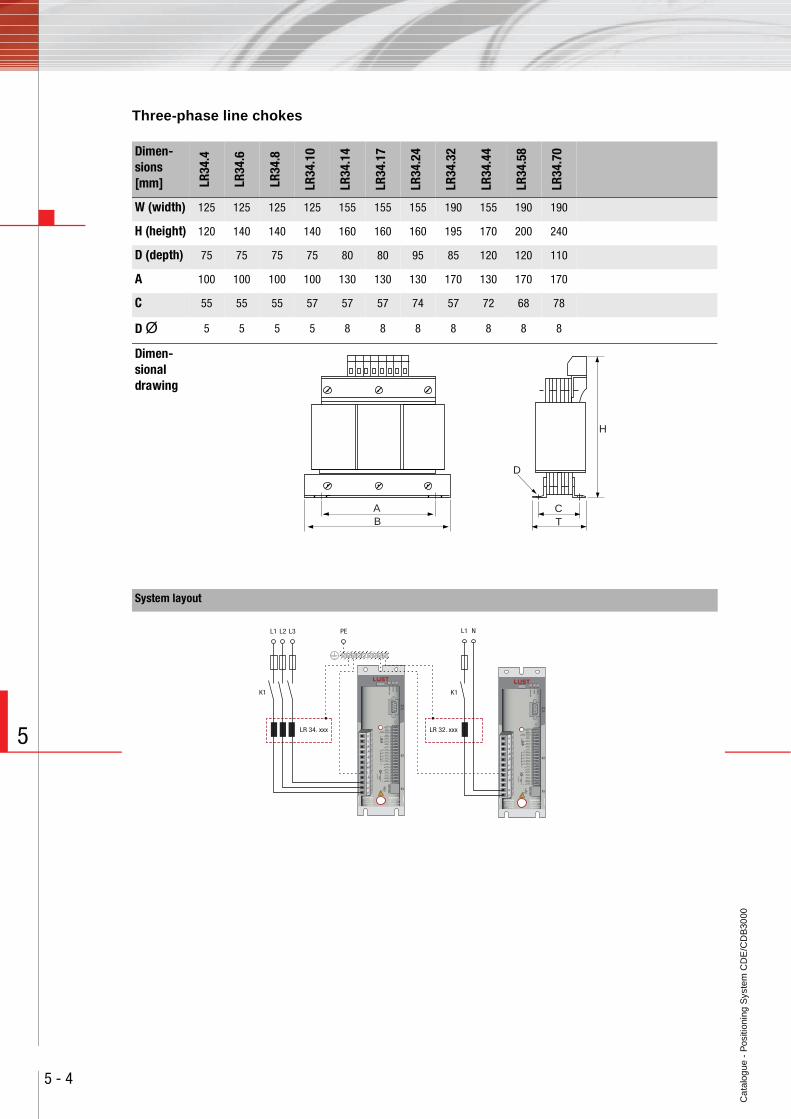
Ca
talo
gue
- P
ositi
onin
g S
yste
m C
DE
/CD
B30
00
5 - 4
5
Three-phase line chokes
Dimen-sions [mm] LR
34.4
LR34
.6
LR34
.8
LR34
.10
LR34
.14
LR34
.17
LR34
.24
LR34
.32
LR34
.44
LR34
.58
LR34
.70
W (width) 125 125 125 125 155 155 155 190 155 190 190
H (height) 120 140 140 140 160 160 160 195 170 200 240
D (depth) 75 75 75 75 80 80 95 85 120 120 110
A 100 100 100 100 130 130 130 170 130 170 170
C 55 55 55 57 57 57 74 57 72 68 78
D Ø 5 5 5 5 8 8 8 8 8 8 8
Dimen-sional drawing
AB
D
CT
H
System layout
U
V
W
L+
RB
L-
L2
L3
L1
U
V
W
L+
RB
L-
N
L1
L1
K1 K1
L2 L3 PE
LR 34. xxx
L1 N
LR 32. xxx
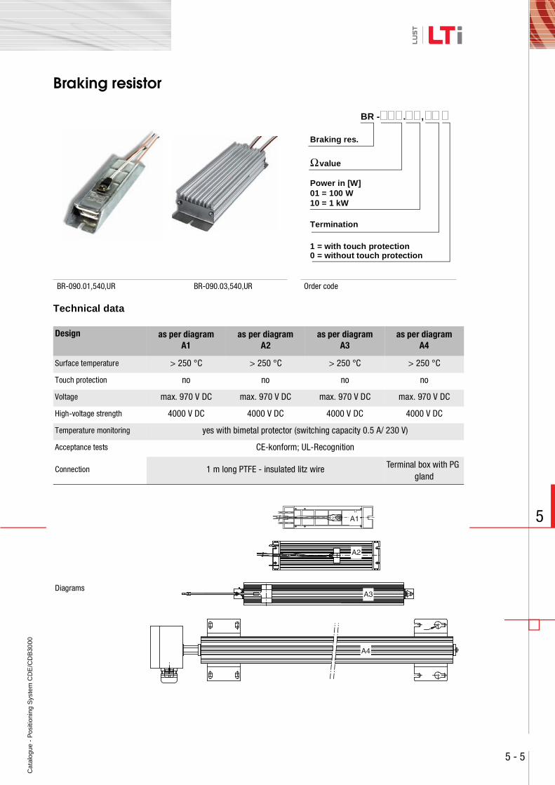
Ca
talo
gue
- P
ositi
onin
g S
yste
m C
DE
/CD
B30
00
5 - 5
5
Braking resistor
Technical data
BR-090.01,540,UR BR-090.03,540,UR Order code
Design as per diagramA1
as per diagramA2
as per diagramA3
as per diagramA4
Surface temperature > 250 °C > 250 °C > 250 °C > 250 °C
Touch protection no no no no
Voltage max. 970 V DC max. 970 V DC max. 970 V DC max. 970 V DC
High-voltage strength 4000 V DC 4000 V DC 4000 V DC 4000 V DC
Temperature monitoring yes with bimetal protector (switching capacity 0.5 A/ 230 V)
Acceptance tests CE-konform; UL-Recognition
Connection 1 m long PTFE - insulated litz wire Terminal box with PGgland
Diagrams
BR - . ,
Ω value
Braking res.
Power in [W]
Termination
0 = without touch protection1 = with touch protection
01 = 100 W10 = 1 kW
A1
A2
A4
A3
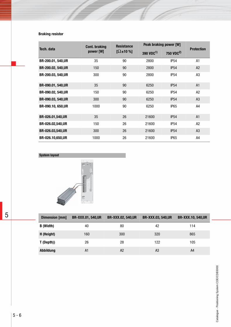
Ca
talo
gue
- P
ositi
onin
g S
yste
m C
DE
/CD
B30
00
5 - 6
5
Braking resistor
Tech. dataCont. braking
power [W]Resistance[Ω ±10 %]
Peak braking power [W]Protection
390 VDC1) 750 VDC2)
BR-200.01, 540,UR 35 90 2800 IP54 A1
BR-200.02, 540,UR 150 90 2800 IP54 A2
BR-200.03, 540,UR 300 90 2800 IP54 A3
BR-090.01, 540,UR 35 90 6250 IP54 A1
BR-090.02, 540,UR 150 90 6250 IP54 A2
BR-090.03, 540,UR 300 90 6250 IP54 A3
BR-090.10, 650,UR 1000 90 6250 IP65 A4
BR-026.01,540,UR 35 26 21600 IP54 A1
BR-026.02,540,UR 150 26 21600 IP54 A2
BR-026.03,540,UR 300 26 21600 IP54 A3
BR-026.10,650,UR 1000 26 21600 IP65 A4
System layout
H1 H2 H3
X4
X2
X1X3
ACHTUNGKondensatorent-ladezeit >3 Min.Betriebsanleitungbeachten!
WARNINGcapacitor disschargetime >3 minutes.Pay attention to theoperation manual!ATTENTIONtemps de dechargedu condensteur>3 min. observer lemode dèmploi!
!
U
V
W
L+
RB
L-
L3
L2
L1
Dimension [mm] BR-XXX.01, 540,UR BR-XXX.02, 540,UR BR-XXX.03, 540,UR BR-XXX.10, 540,UR
B (Width) 40 80 42 114
H (Height) 160 300 320 865
T (Depth)) 26 28 122 105
Abbildung A1 A2 A3 A4
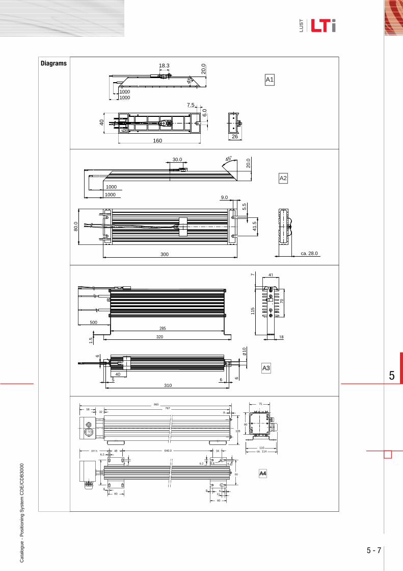
Ca
talo
gue
- P
ositi
onin
g S
yste
m C
DE
/CD
B30
00
5 - 7
5
Diagrams 18.3
26
6.0
1000
7.5
160
45°
1000
40
6
20.0
A1
300 ca. 28.0
45°
1000
80.0
20.030.0
41.5
5.5
9.01000
A2
5
6
1.5
6
310
285
320
417
18
115
70
406
Ø 10
500
A3A3
58 32
105
8
107.5 48 6.2
6
90
6
60
6.2
34
6.2 R 6
6
60
9
75
80
110 ca. 114
11
767 865
640.0
90 A4A4
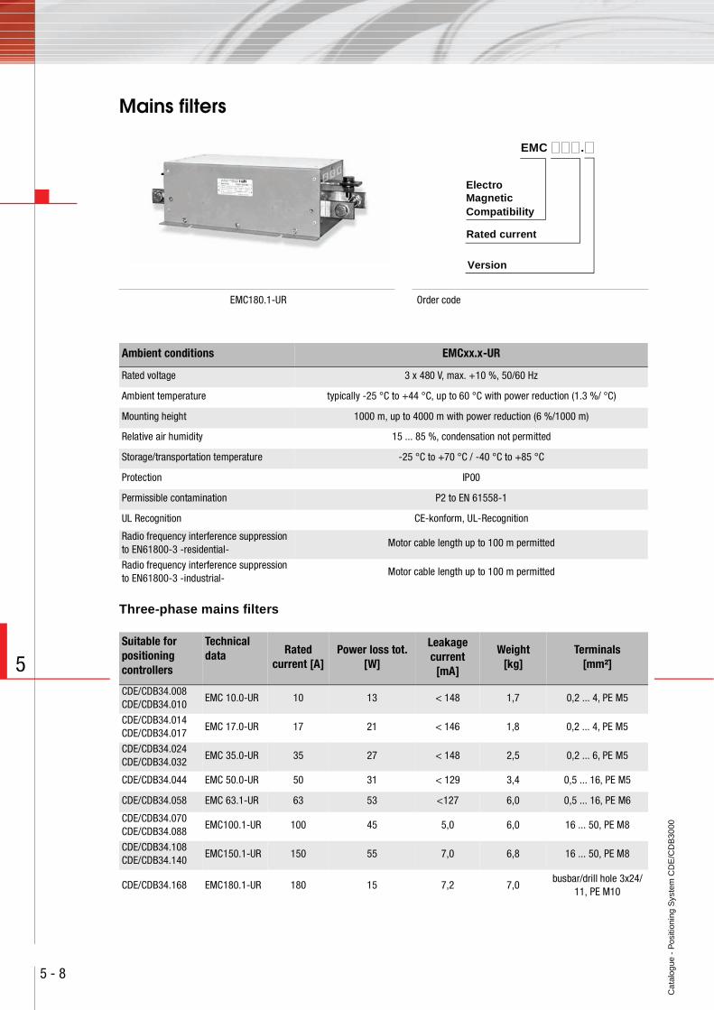
Ca
talo
gue
- P
ositi
onin
g S
yste
m C
DE
/CD
B30
00
5 - 8
5
Mains filters
Three-phase mains filters
EMC180.1-UR Order code
Version
Rated current
EMC .
Electro
CompatibilityMagnetic
Ambient conditions EMCxx.x-UR
Rated voltage 3 x 480 V, max. +10 %, 50/60 Hz
Ambient temperature typically -25 °C to +44 °C, up to 60 °C with power reduction (1.3 %/ °C)
Mounting height 1000 m, up to 4000 m with power reduction (6 %/1000 m)
Relative air humidity 15 ... 85 %, condensation not permitted
Storage/transportation temperature -25 °C to +70 °C / -40 °C to +85 °C
Protection IP00
Permissible contamination P2 to EN 61558-1
UL Recognition CE-konform, UL-Recognition
Radio frequency interference suppression to EN61800-3 -residential-
Motor cable length up to 100 m permitted
Radio frequency interference suppression to EN61800-3 -industrial-
Motor cable length up to 100 m permitted
Suitable for positioning controllers
Technical data Rated
current [A]Power loss tot.
[W]
Leakage current
[mA]
Weight [kg]
Terminals[mm²]
CDE/CDB34.008CDE/CDB34.010
EMC 10.0-UR 10 13 < 148 1,7 0,2 ... 4, PE M5
CDE/CDB34.014CDE/CDB34.017
EMC 17.0-UR 17 21 < 146 1,8 0,2 ... 4, PE M5
CDE/CDB34.024CDE/CDB34.032
EMC 35.0-UR 35 27 < 148 2,5 0,2 ... 6, PE M5
CDE/CDB34.044 EMC 50.0-UR 50 31 < 129 3,4 0,5 ... 16, PE M5
CDE/CDB34.058 EMC 63.1-UR 63 53 <127 6,0 0,5 ... 16, PE M6
CDE/CDB34.070CDE/CDB34.088
EMC100.1-UR 100 45 5,0 6,0 16 ... 50, PE M8
CDE/CDB34.108CDE/CDB34.140
EMC150.1-UR 150 55 7,0 6,8 16 ... 50, PE M8
CDE/CDB34.168 EMC180.1-UR 180 15 7,2 7,0busbar/drill hole 3x24/
11, PE M10
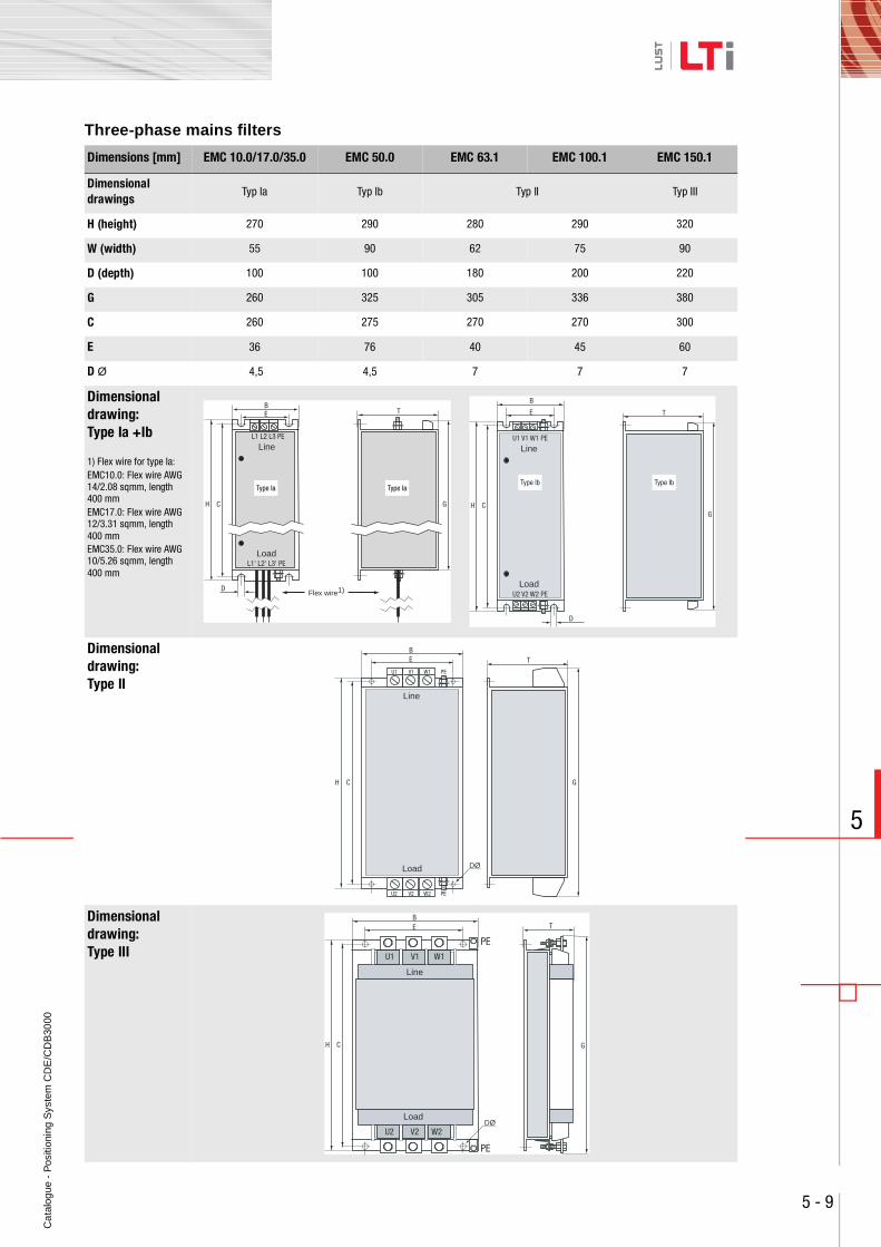
Ca
talo
gue
- P
ositi
onin
g S
yste
m C
DE
/CD
B30
00
5 - 9
5
Three-phase mains filters
Dimensions [mm] EMC 10.0/17.0/35.0 EMC 50.0 EMC 63.1 EMC 100.1 EMC 150.1
Dimensional drawings
Typ Ia Typ Ib Typ II Typ III
H (height) 270 290 280 290 320
W (width) 55 90 62 75 90
D (depth) 100 100 180 200 220
G 260 325 305 336 380
C 260 275 270 270 300
E 36 76 40 45 60
D Ø 4,5 4,5 7 7 7
Dimensional drawing: Type Ia +Ib
1) Flex wire for type Ia:EMC10.0: Flex wire AWG 14/2.08 sqmm, length 400 mmEMC17.0: Flex wire AWG 12/3.31 sqmm, length 400 mmEMC35.0: Flex wire AWG 10/5.26 sqmm, length 400 mm
Dimensional drawing: Type II
Dimensional drawing: Type III
Line
Flex wire1)
LoadL1' L2' L3' PE
L1 L2 L3 PE
B
C GH
TE
D
Type Ia Type Ia
Line
LoadU2 V2 W2 PE
U1 V1 W1 PE
B
CG
H
TE
D
Type Ib Type Ib
Line
Load
U1 V1 W1 PE
B
C GH
TE
DØ
U2 V2 W2 PE
B
PE
PE
CH
E
DØ
G
T
U1 V1 W1
U2 V2 W2
Line
Load
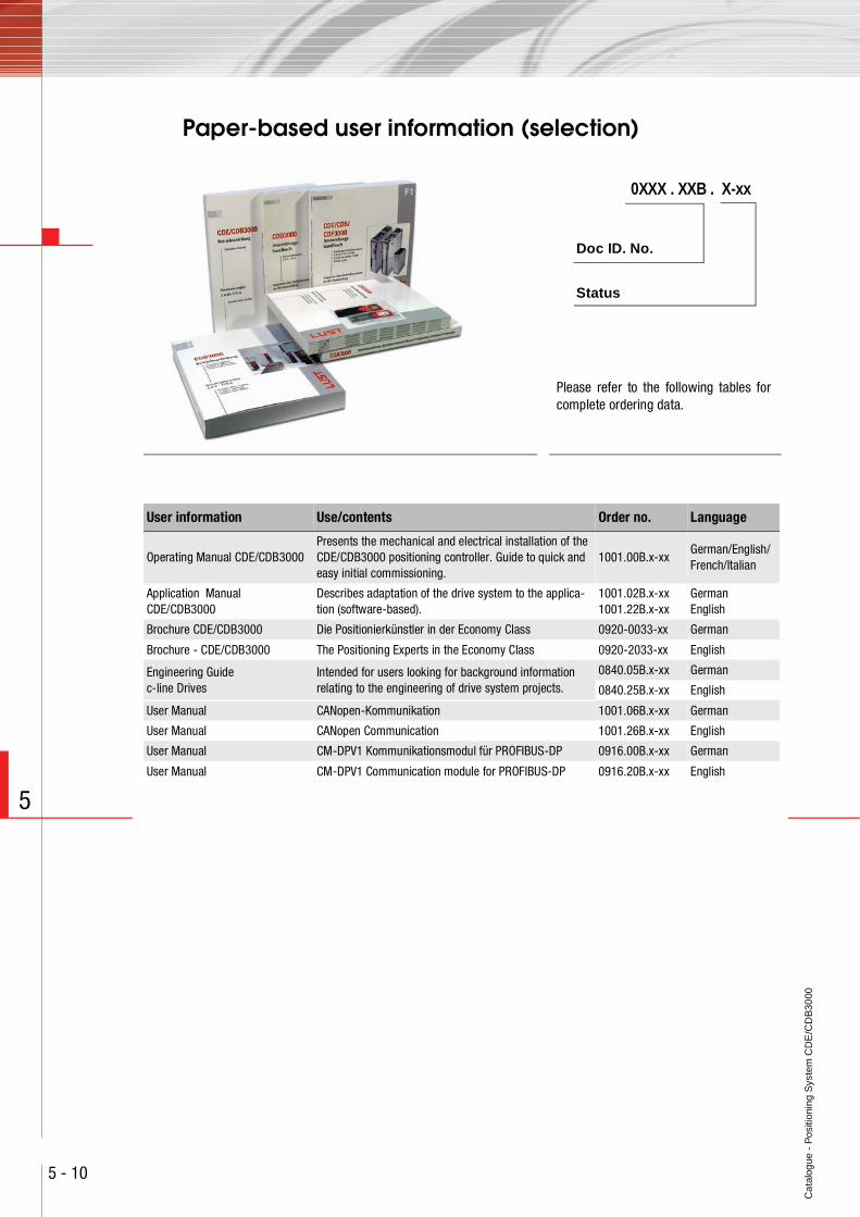
Ca
talo
gue
- P
ositi
onin
g S
yste
m C
DE
/CD
B30
00
5 - 10
5
Paper-based user information (selection)
New picture
0XXX . XXB . X-xx
Doc ID. No.
Status
Please refer to the following tables forcomplete ordering data.
User information Use/contents Order no. Language
Operating Manual CDE/CDB3000 Presents the mechanical and electrical installation of the CDE/CDB3000 positioning controller. Guide to quick and easy initial commissioning.
1001.00B.x-xxGerman/English/French/Italian
Application Manual CDE/CDB3000
Describes adaptation of the drive system to the applica-tion (software-based).
1001.02B.x-xx1001.22B.x-xx
GermanEnglish
Brochure CDE/CDB3000 Die Positionierkünstler in der Economy Class 0920-0033-xx German
Brochure - CDE/CDB3000 The Positioning Experts in the Economy Class 0920-2033-xx English
Engineering Guide c-line Drives
Intended for users looking for background information relating to the engineering of drive system projects.
0840.05B.x-xx German
0840.25B.x-xx English
User Manual CANopen-Kommunikation 1001.06B.x-xx German
User Manual CANopen Communication 1001.26B.x-xx English
User Manual CM-DPV1 Kommunikationsmodul für PROFIBUS-DP 0916.00B.x-xx German
User Manual CM-DPV1 Communication module for PROFIBUS-DP 0916.20B.x-xx English
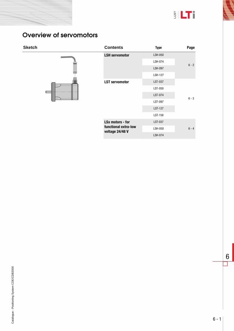
Cat
alog
ue -
Pos
ition
ing
Sys
tem
CD
E/C
DB
300
0
6 - 1
6
Overview of servomotors
Sketch Contents Type Page
LSH servomotor LSH-050
6 - 2LSH-074
LSH-097
LSH-127
LST servomotor LST-037
6 - 3
LST-050
LST-074
LST-097
LST-127
LST-158
LSx motors - for functional extra-low voltage 24/48 V
LST-037
6 - 4LSH-050
LSH-074
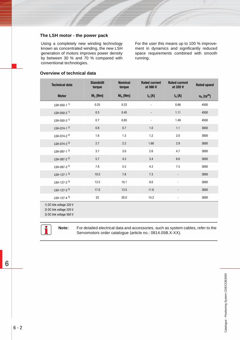
Cat
alog
ue -
Pos
ition
ing
Sys
tem
CD
E/C
DB
3000
6 - 2
6
The LSH motor - the power pack
Overview of technical data
Note: For detailed electrical data and accessories, such as system cables, refer to the Servomotors order catalogue (article no.: 0814.05B.X-XX).
Using a completely new winding technologyknown as concentrated winding, the new LSHgeneration of motors improves power densityby between 30 % and 70 % compared withconventional technologies.
For the user this means up to 100 % improve-ment in dynamics and significantly reducedspace requirements combined with smoothrunning.
Technical dataStandstill
torqueNominaltorque
Rated currentat 560 V
Rated currentat 320 V
Rated speed
Motor M0 [Nm] MN [Nm] IN [A] IN [A] nN [rpm]
LSH-050-1 1) 0.25 0.23 - 0.66 4500
LSH-050-2 1) 0.5 0.45 - 1.11 4500
LSH-050-3 1) 0.7 0.65 - 1.49 4500
LSH-074-1 2) 0.8 0.7 1.0 1.1 3000
LSH-074-2 2) 1.6 1.3 1.2 2.0 3000
LSH-074-3 2) 2.7 2.2 1.68 2.9 3000
LSH-097-1 2) 3.7 3.0 2.6 4.7 3000
LSH-097-2 2) 5.7 4.3 3.4 6.6 3000
LSH-097-3 2) 7.8 5.5 4.3 7.5 3000
LSH-127-1 3) 10.5 7.8 7.3 - 3000
LSH-127-2 3) 13.5 10.1 9.0 - 3000
LSH-127-3 3) 17.0 13.5 11.6 - 3000
LSH-127-4 3) 25 20.0 14.2 - 3000
1) DC link voltage 320 V
2) DC link voltage 320 V
3) DC link voltage 560 V
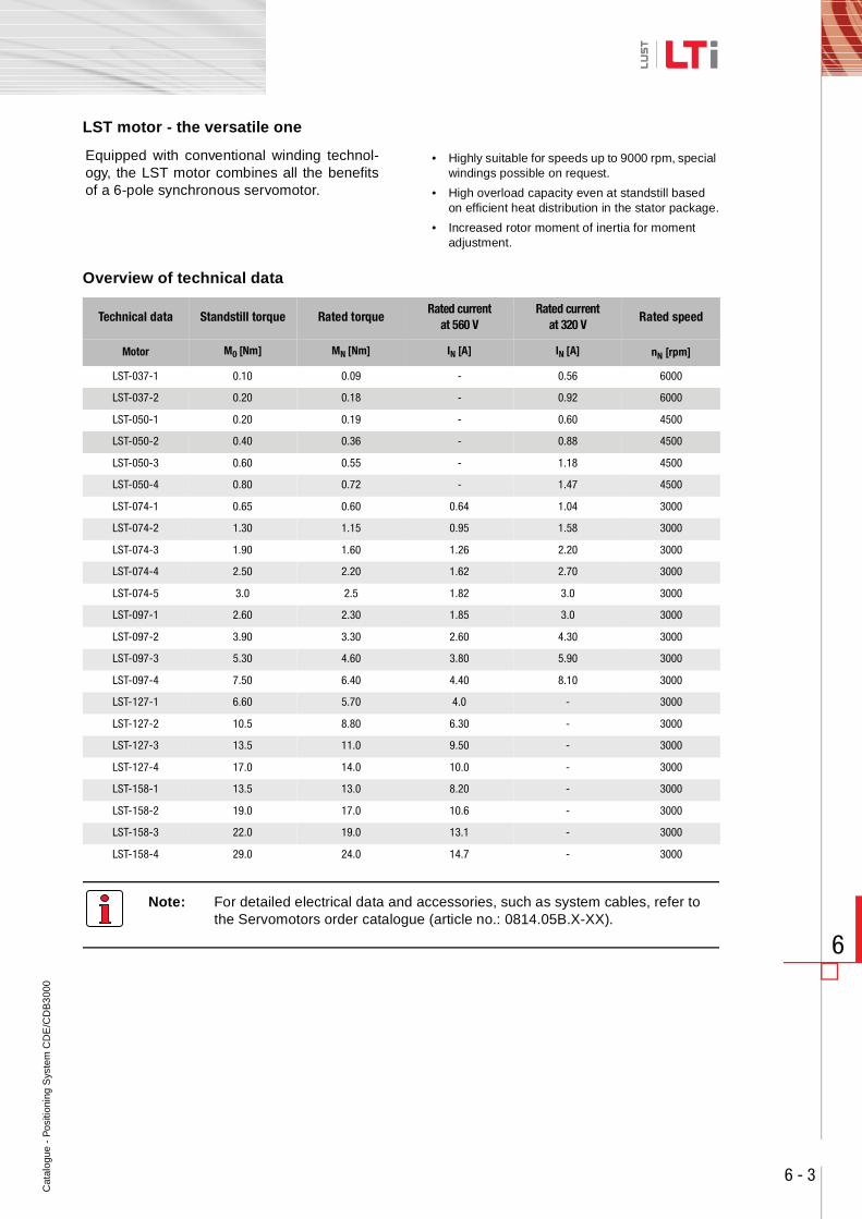
Cat
alog
ue -
Pos
ition
ing
Sys
tem
CD
E/C
DB
300
0
6 - 3
6
LST motor - the versatile one
Overview of technical data
Note: For detailed electrical data and accessories, such as system cables, refer to the Servomotors order catalogue (article no.: 0814.05B.X-XX).
Equipped with conventional winding technol-ogy, the LST motor combines all the benefitsof a 6-pole synchronous servomotor.
• Highly suitable for speeds up to 9000 rpm, special windings possible on request.
• High overload capacity even at standstill based on efficient heat distribution in the stator package.
• Increased rotor moment of inertia for moment adjustment.
Technical data Standstill torque Rated torqueRated current
at 560 VRated current
at 320 VRated speed
Motor M0 [Nm] MN [Nm] IN [A] IN [A] nN [rpm]
LST-037-1 0.10 0.09 - 0.56 6000
LST-037-2 0.20 0.18 - 0.92 6000
LST-050-1 0.20 0.19 - 0.60 4500
LST-050-2 0.40 0.36 - 0.88 4500
LST-050-3 0.60 0.55 - 1.18 4500
LST-050-4 0.80 0.72 - 1.47 4500
LST-074-1 0.65 0.60 0.64 1.04 3000
LST-074-2 1.30 1.15 0.95 1.58 3000
LST-074-3 1.90 1.60 1.26 2.20 3000
LST-074-4 2.50 2.20 1.62 2.70 3000
LST-074-5 3.0 2.5 1.82 3.0 3000
LST-097-1 2.60 2.30 1.85 3.0 3000
LST-097-2 3.90 3.30 2.60 4.30 3000
LST-097-3 5.30 4.60 3.80 5.90 3000
LST-097-4 7.50 6.40 4.40 8.10 3000
LST-127-1 6.60 5.70 4.0 - 3000
LST-127-2 10.5 8.80 6.30 - 3000
LST-127-3 13.5 11.0 9.50 - 3000
LST-127-4 17.0 14.0 10.0 - 3000
LST-158-1 13.5 13.0 8.20 - 3000
LST-158-2 19.0 17.0 10.6 - 3000
LST-158-3 22.0 19.0 13.1 - 3000
LST-158-4 29.0 24.0 14.7 - 3000
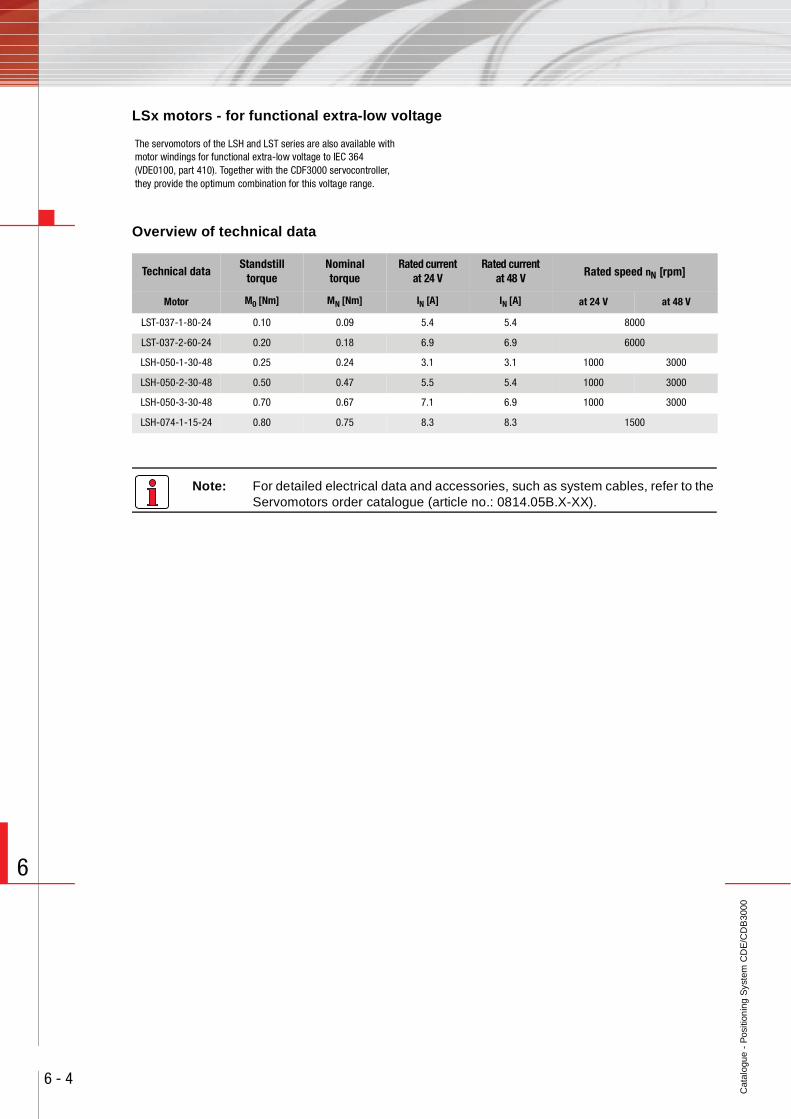
Cat
alog
ue -
Pos
ition
ing
Sys
tem
CD
E/C
DB
3000
6 - 4
6
LSx motors - for functional extra-low voltage
Overview of technical data
Note: For detailed electrical data and accessories, such as system cables, refer to the Servomotors order catalogue (article no.: 0814.05B.X-XX).
The servomotors of the LSH and LST series are also available with motor windings for functional extra-low voltage to IEC 364 (VDE0100, part 410). Together with the CDF3000 servocontroller, they provide the optimum combination for this voltage range.
Technical dataStandstill
torqueNominaltorque
Rated currentat 24 V
Rated currentat 48 V Rated speed nN [rpm]
Motor M0 [Nm] MN [Nm] IN [A] IN [A] at 24 V at 48 V
LST-037-1-80-24 0.10 0.09 5.4 5.4 8000
LST-037-2-60-24 0.20 0.18 6.9 6.9 6000
LSH-050-1-30-48 0.25 0.24 3.1 3.1 1000 3000
LSH-050-2-30-48 0.50 0.47 5.5 5.4 1000 3000
LSH-050-3-30-48 0.70 0.67 7.1 6.9 1000 3000
LSH-074-1-15-24 0.80 0.75 8.3 8.3 1500

LTi DRiVES GmbH
Gewerbestraße 5-935633 LahnauGermany
Fon +49 (0) 6441/ 96 6-0Fax:+49 (0) 6441/ 96 6-137
Heinrich-Hertz-Straße 1859423 UnnaGermany
Fon +49 (0) 2303/ 77 9-0Fax:+49 (0) 2303/ 77 9-397
We reserve the right to make technical changes.
The content of our Order Catalogue was compiled with the greatest care and attention, and based on the lat-est information available to us.We should nevertheless point out that this document cannot always be updated in line with ongoing techni-cal developments in our products.
Information and specifications may be subjectto change at any time. Please visit www.lt-i.com for details of the latest versions.
Cataloque - CDE/CDB3000Id.-Nr.: 1001.24B.5-00 Stand 11/2008