Embed Size (px)
Citation preview
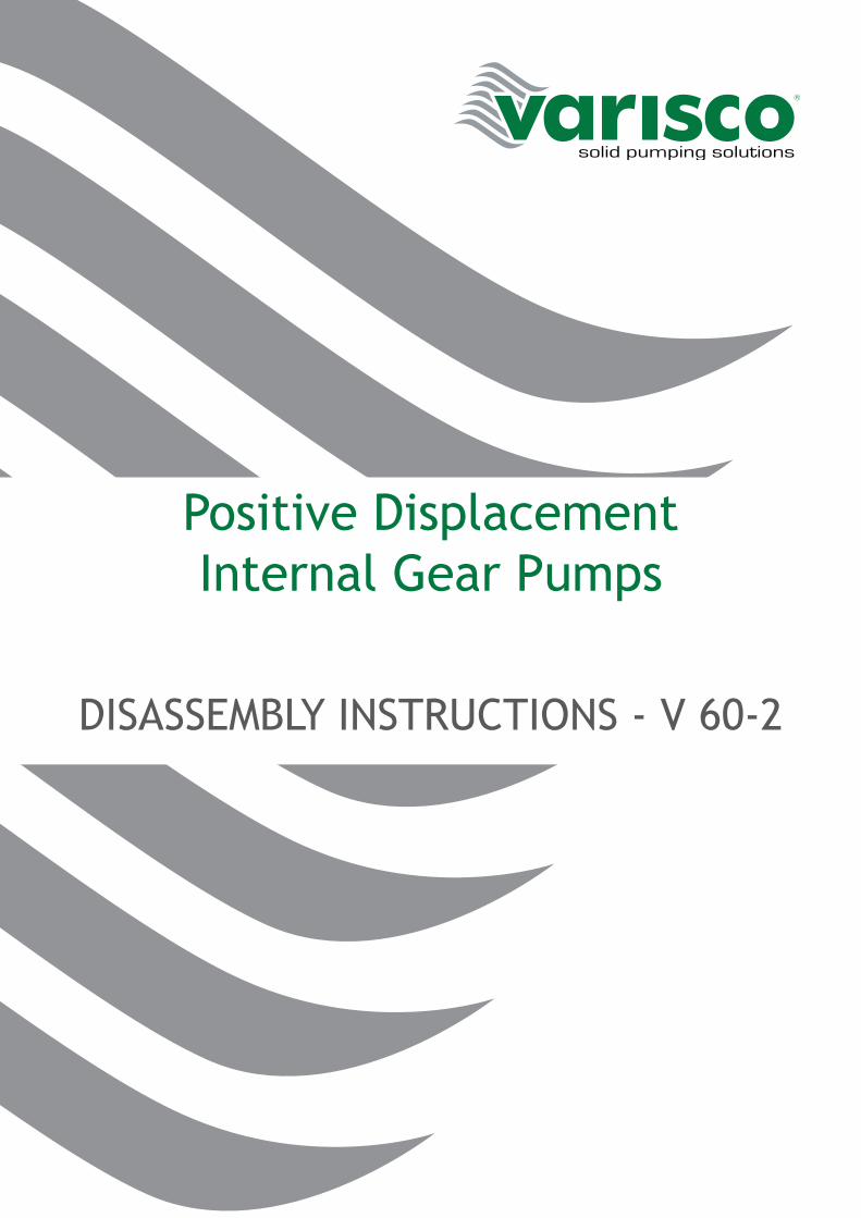
Positive DisplacementInternal Gear Pumps
DISASSEMBLY INSTRUCTIONS - V 60-2
2
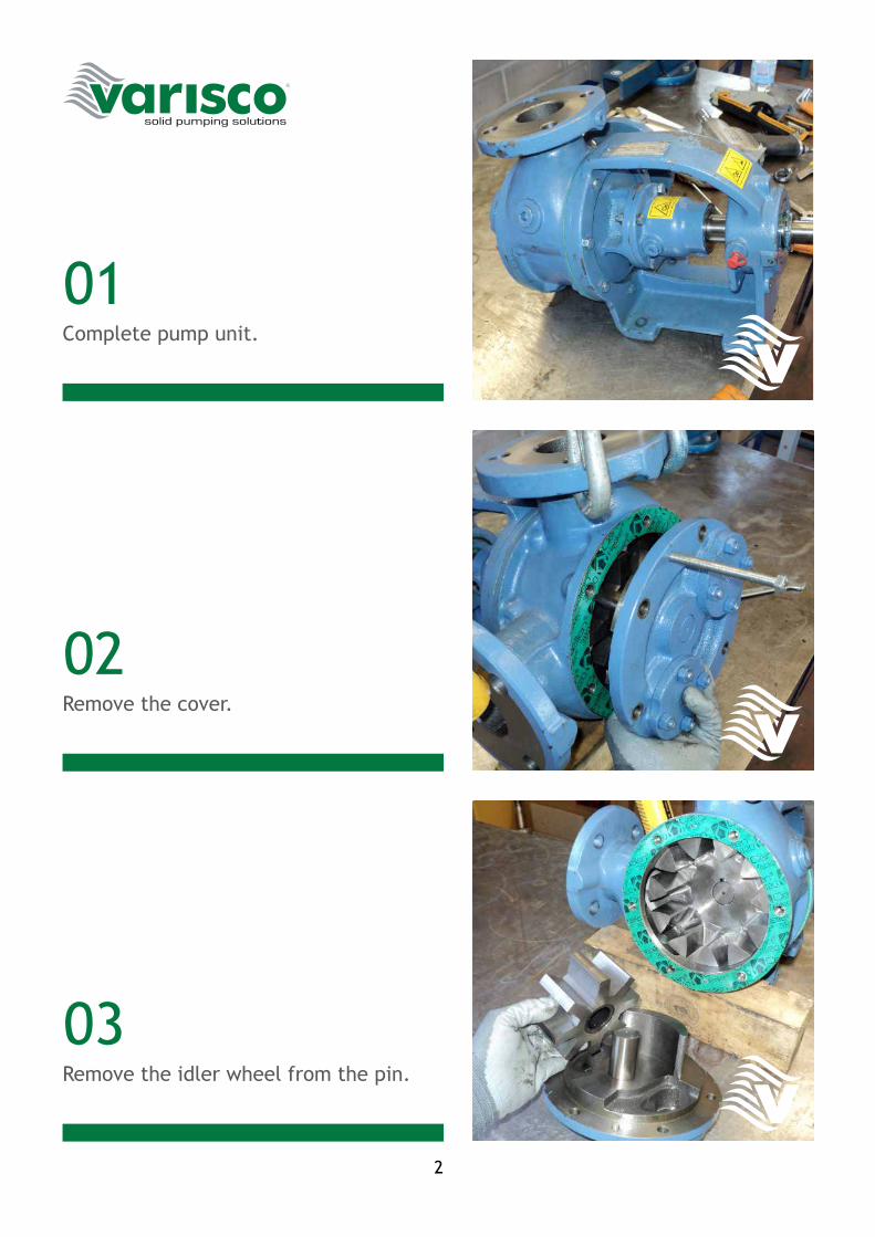
01
02
03
Complete pump unit.
Remove the cover.
Remove the idler wheel from the pin.

3
04
05
06
Set the pump upright.
Remove the top of the shaft.
Release the safety washer by bending it outwards.
4
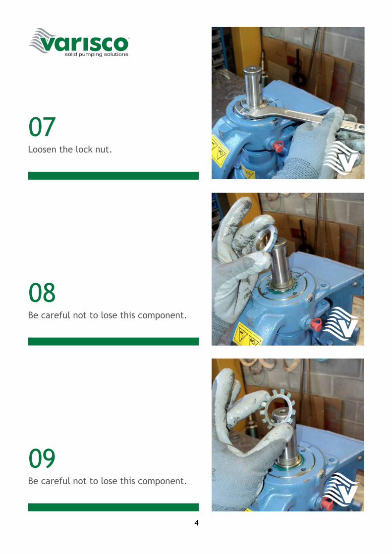
07
08
09
Loosen the lock nut.
Be careful not to lose this component.
Be careful not to lose this component.
5
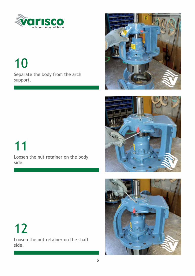
10
11
12
Separate the body from the arch support.
Loosen the nut retainer on the body side.
Loosen the nut retainer on the shaft side.
6
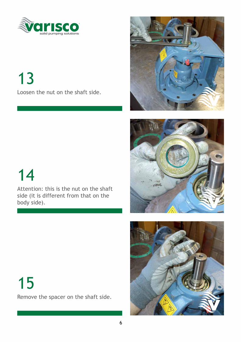
13
14
15
Loosen the nut on the shaft side.
Attention: this is the nut on the shaft side (it is different from that on the body side).
Remove the spacer on the shaft side.
7
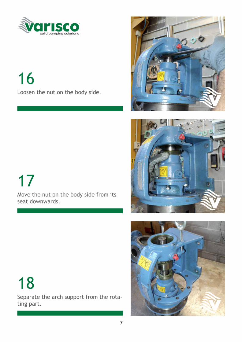
16
17
18
Loosen the nut on the body side.
Move the nut on the body side from its seat downwards.
Separate the arch support from the rota-ting part.
8
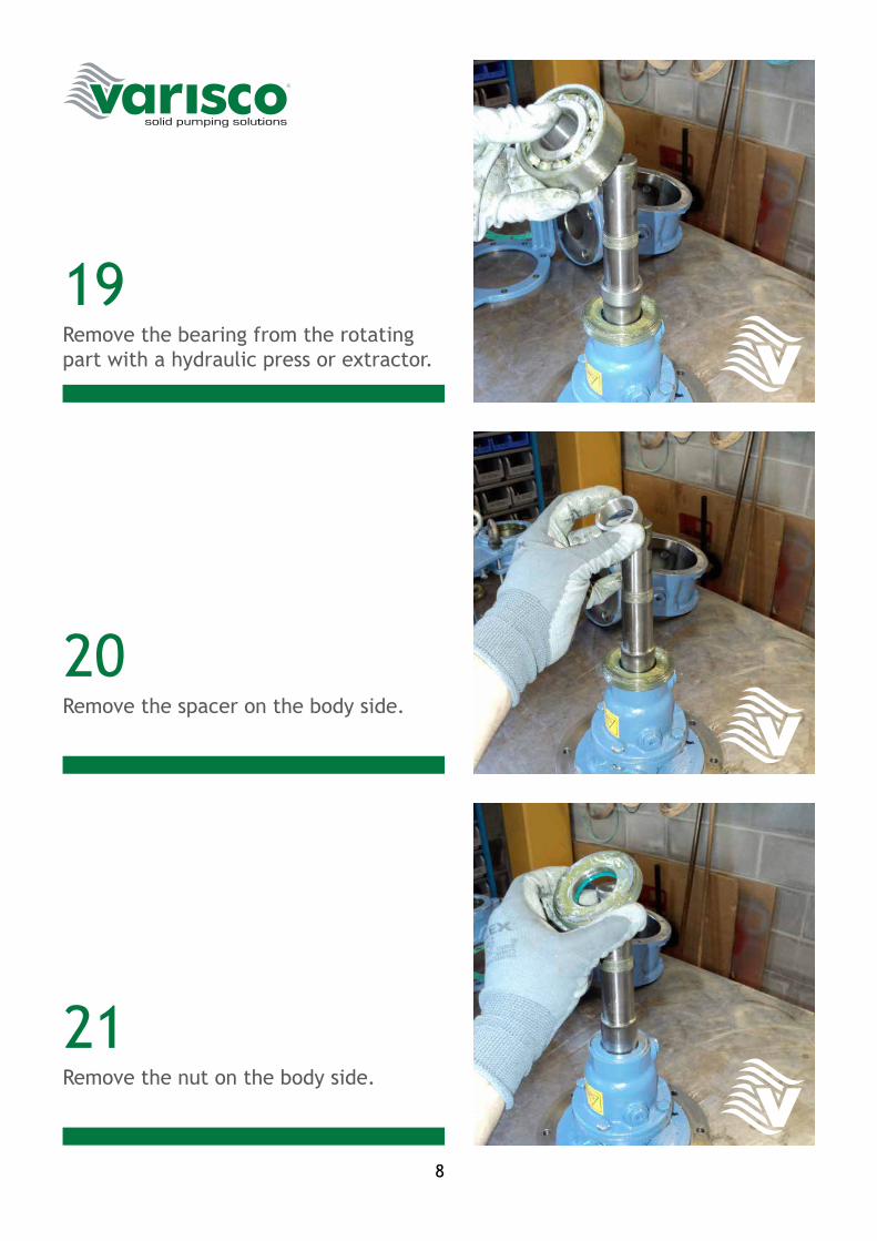
19
20
21
Remove the bearing from the rotating part with a hydraulic press or extractor.
Remove the spacer on the body side.
Remove the nut on the body side.
9
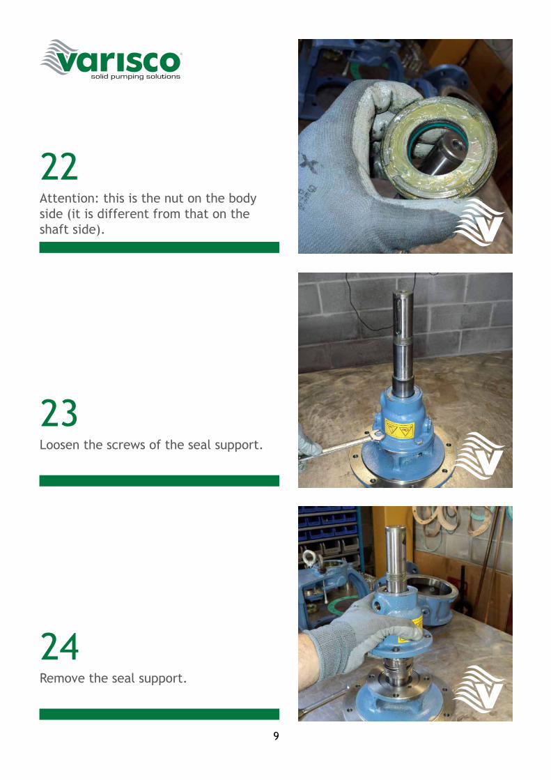
22
23
24
Attention: this is the nut on the body side (it is different from that on the shaft side).
Loosen the screws of the seal support.
Remove the seal support.
10
25
26
27
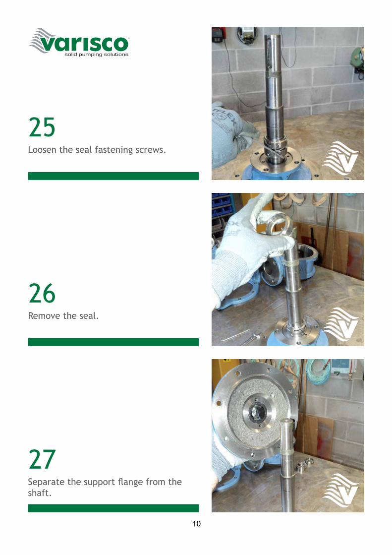
Loosen the seal fastening screws.
Remove the seal.
Separate the support flange from the shaft.
11
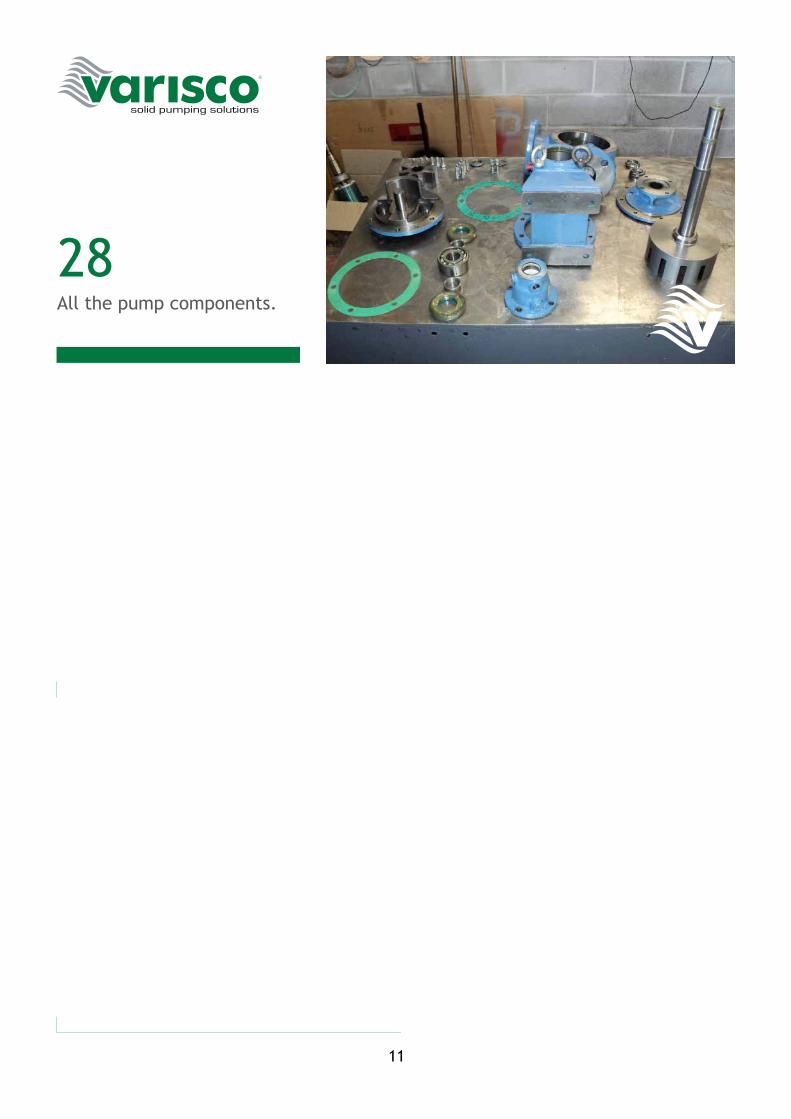
28All the pump components.

12
Positive DisplacementInternal Gear Pumps
ASSEMBLY INSTRUCTIONS - V 60-2
14
01
02
03
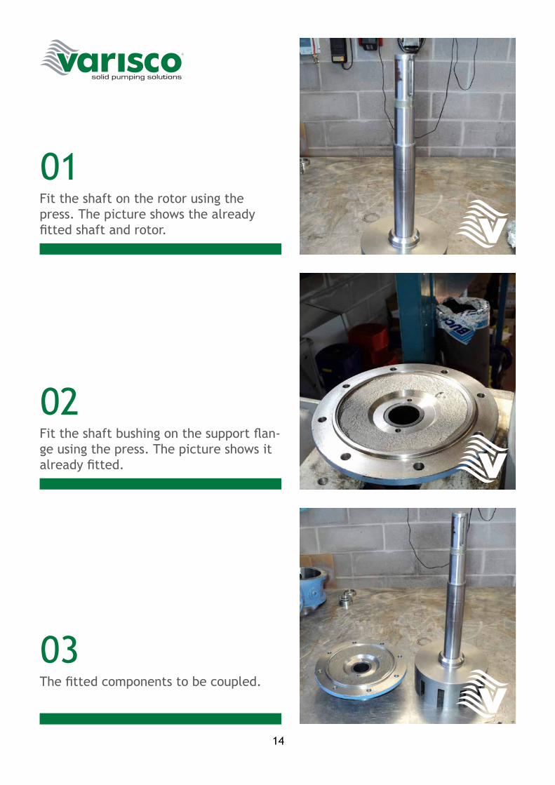
Fit the shaft on the rotor using the press. The picture shows the already fitted shaft and rotor.
Fit the shaft bushing on the support flan-ge using the press. The picture shows it already fitted.
The fitted components to be coupled.
15
04
05
06
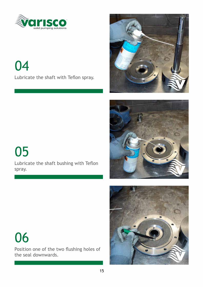
Lubricate the shaft with Teflon spray.
Lubricate the shaft bushing with Teflon spray.
Position one of the two flushing holes of the seal downwards.
16
07
08
09
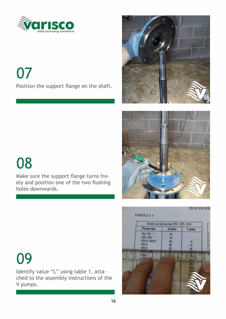
Position the support flange on the shaft.
Make sure the support flange turns fre-ely and position one of the two flushing holes downwards.
Identify value “L” using table 1, atta-ched to the assembly instructions of the V pumps.
17
10
11
12
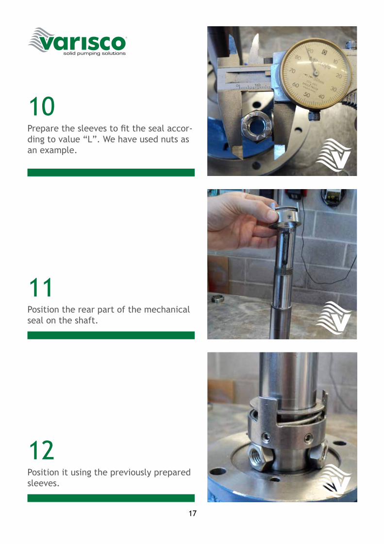
Prepare the sleeves to fit the seal accor-ding to value “L”. We have used nuts as an example.
Position the rear part of the mechanical seal on the shaft.
Position it using the previously prepared sleeves.
18
13
14
15
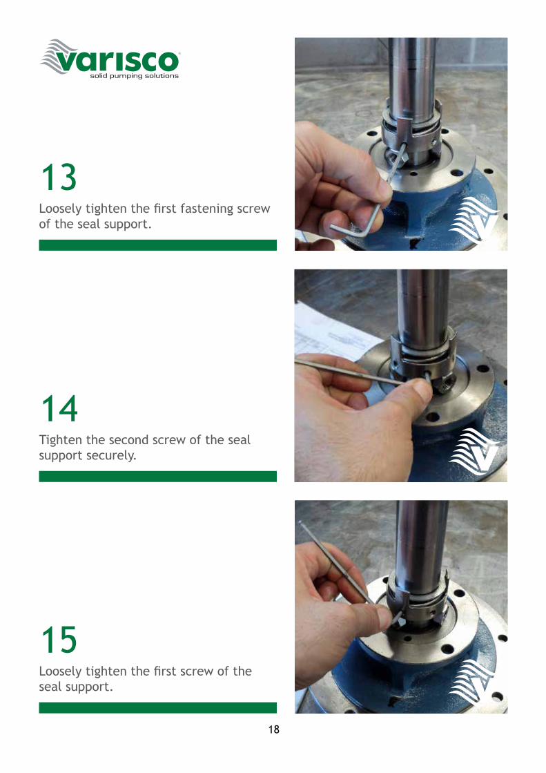
Loosely tighten the first fastening screw of the seal support.
Tighten the second screw of the seal support securely.
Loosely tighten the first screw of the seal support.
19
16
17
18
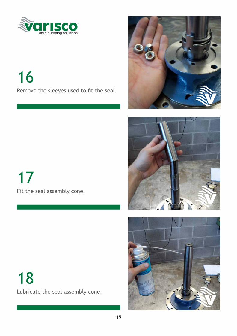
Remove the sleeves used to fit the seal.
Fit the seal assembly cone.
Lubricate the seal assembly cone.
20
19
20
21
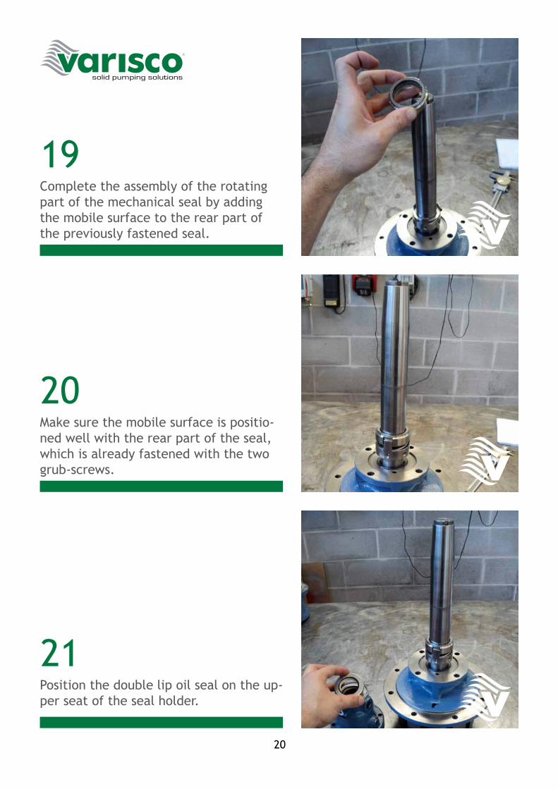
Complete the assembly of the rotating part of the mechanical seal by adding the mobile surface to the rear part of the previously fastened seal.
Make sure the mobile surface is positio-ned well with the rear part of the seal, which is already fastened with the two grub-screws.
Position the double lip oil seal on the up-per seat of the seal holder.
21
22
23
24
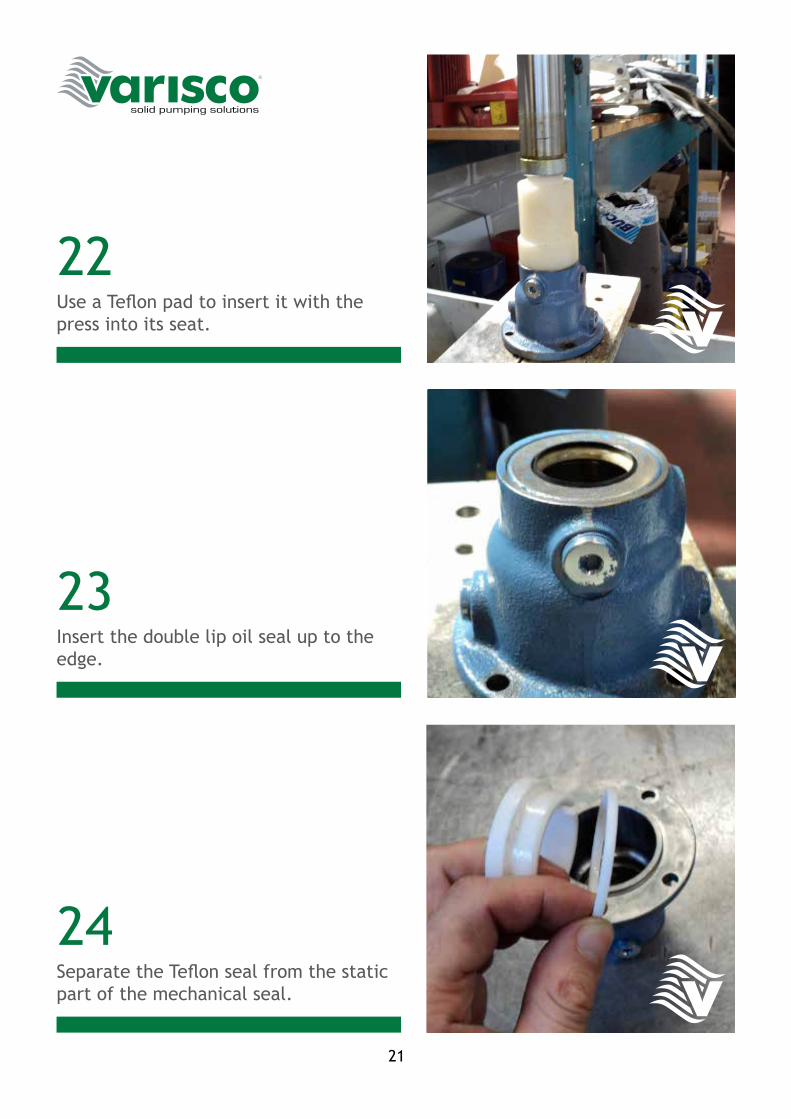
Use a Teflon pad to insert it with the press into its seat.
Insert the double lip oil seal up to the edge.
Separate the Teflon seal from the static part of the mechanical seal.

22
25
26
27
Fit the seal that has just been separated in the seat of the seal holder, while ma-king sure it adheres as best as possible in its seat.
Lubricate the seal that has just been fitted.
Fit the static part of the mechanical seal.
23
28
29
30
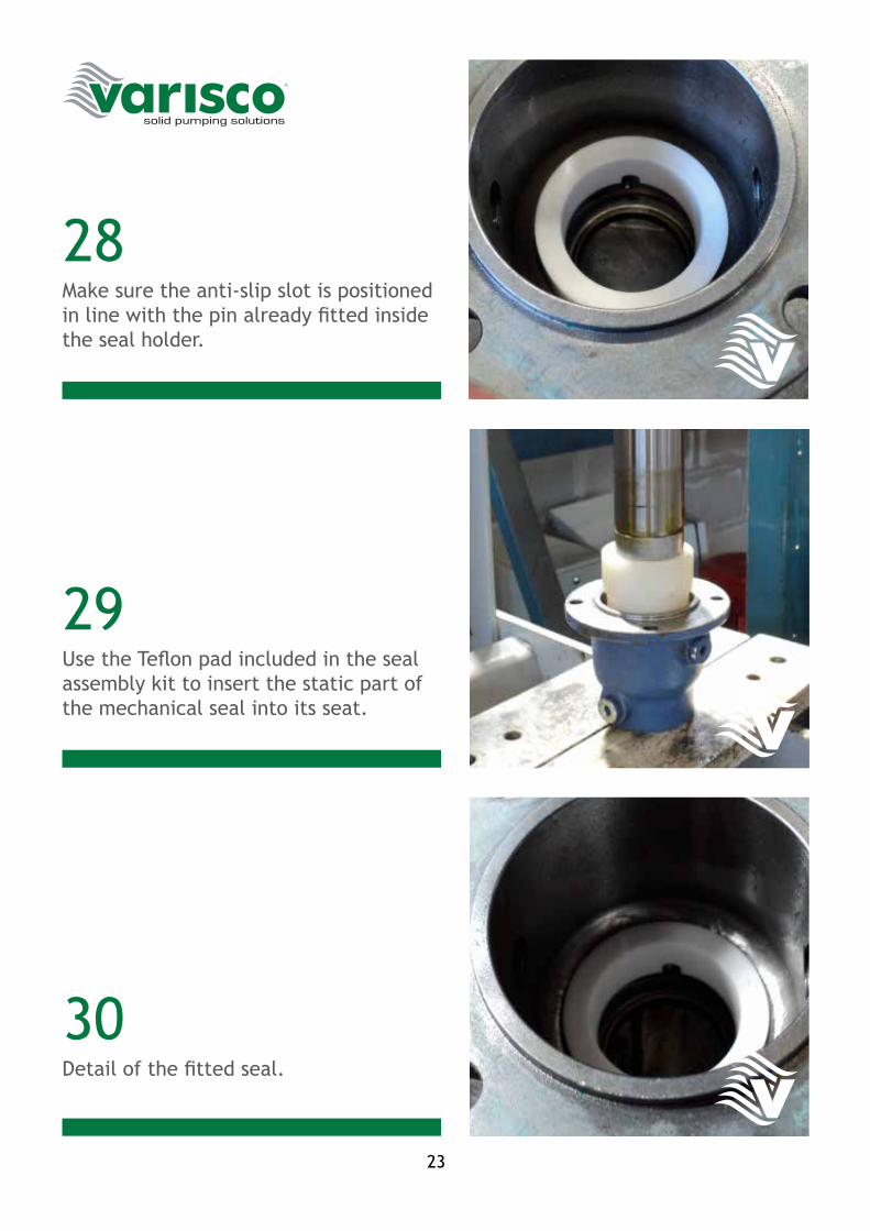
Make sure the anti-slip slot is positioned in line with the pin already fitted inside the seal holder.
Use the Teflon pad included in the seal assembly kit to insert the static part of the mechanical seal into its seat.
Detail of the fitted seal.
24
31
32
33
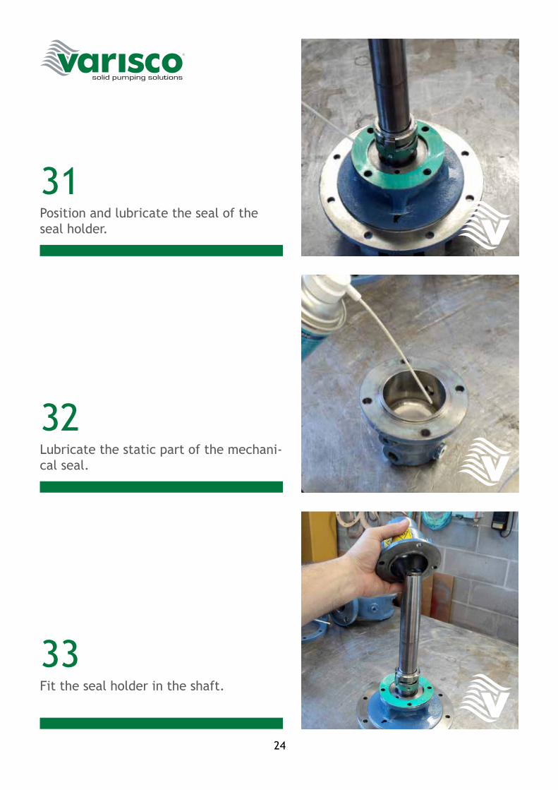
Position and lubricate the seal of the seal holder.
Lubricate the static part of the mechani-cal seal.
Fit the seal holder in the shaft.
25
34
35
36
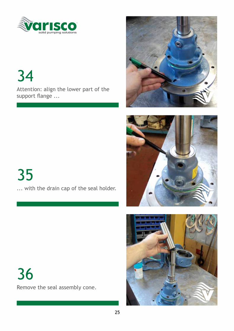
Attention: align the lower part of the support flange ...
... with the drain cap of the seal holder.
Remove the seal assembly cone.
26
37
38
39
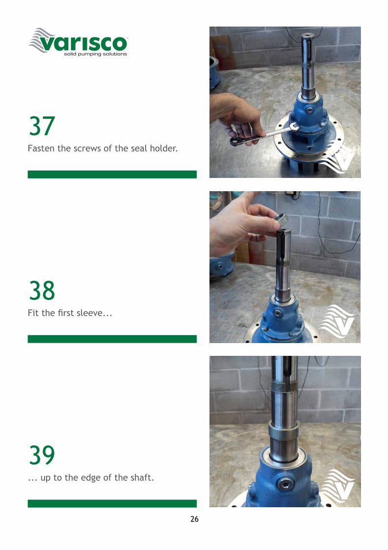
Fasten the screws of the seal holder.
Fit the first sleeve...
... up to the edge of the shaft.
27
40
41
42
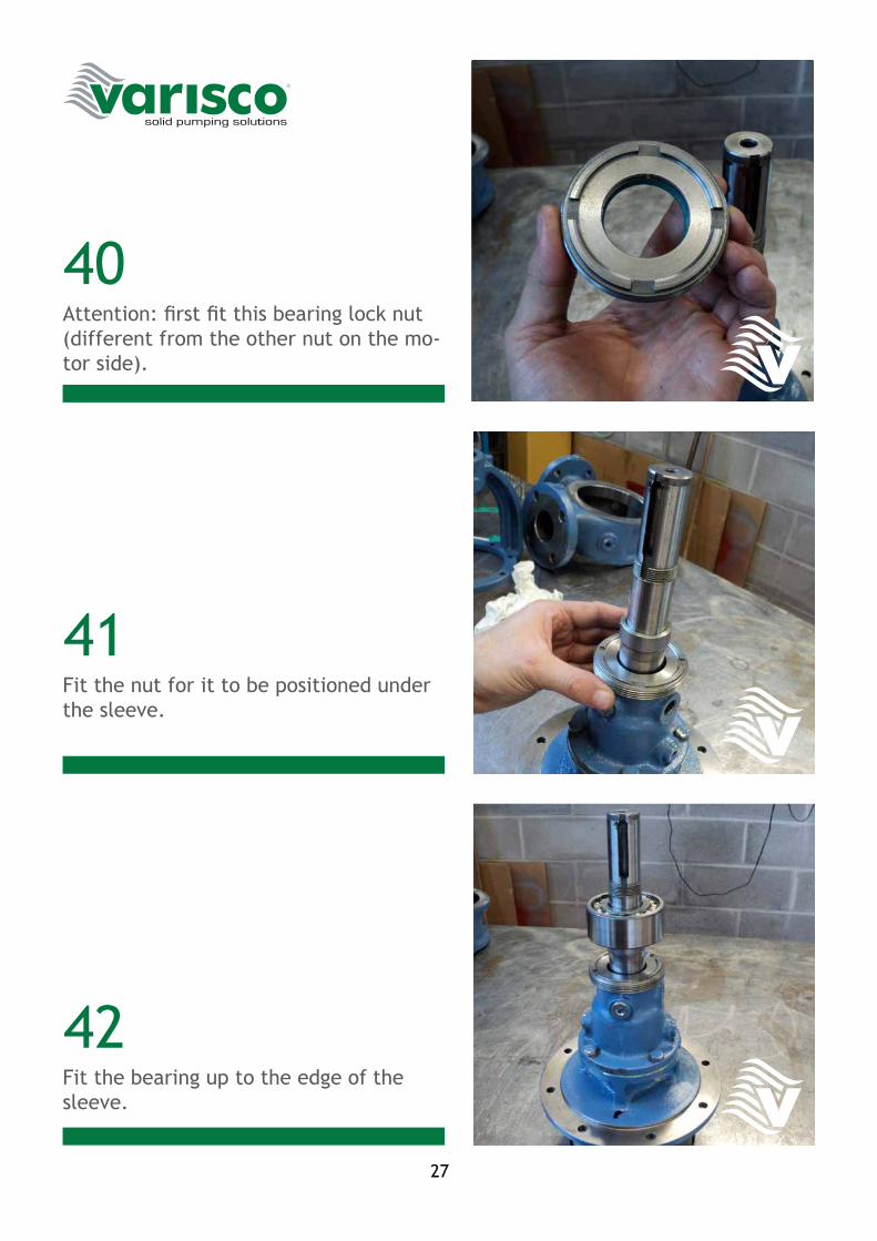
Attention: first fit this bearing lock nut (different from the other nut on the mo-tor side).
Fit the nut for it to be positioned under the sleeve.
Fit the bearing up to the edge of the sleeve.
28
43
44
45
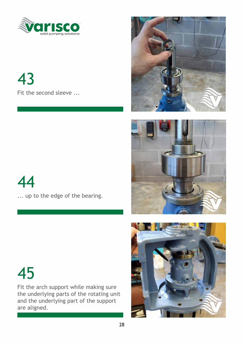
Fit the second sleeve ...
... up to the edge of the bearing.
Fit the arch support while making sure the underlying parts of the rotating unit and the underlying part of the support are aligned.
29
46
47
48
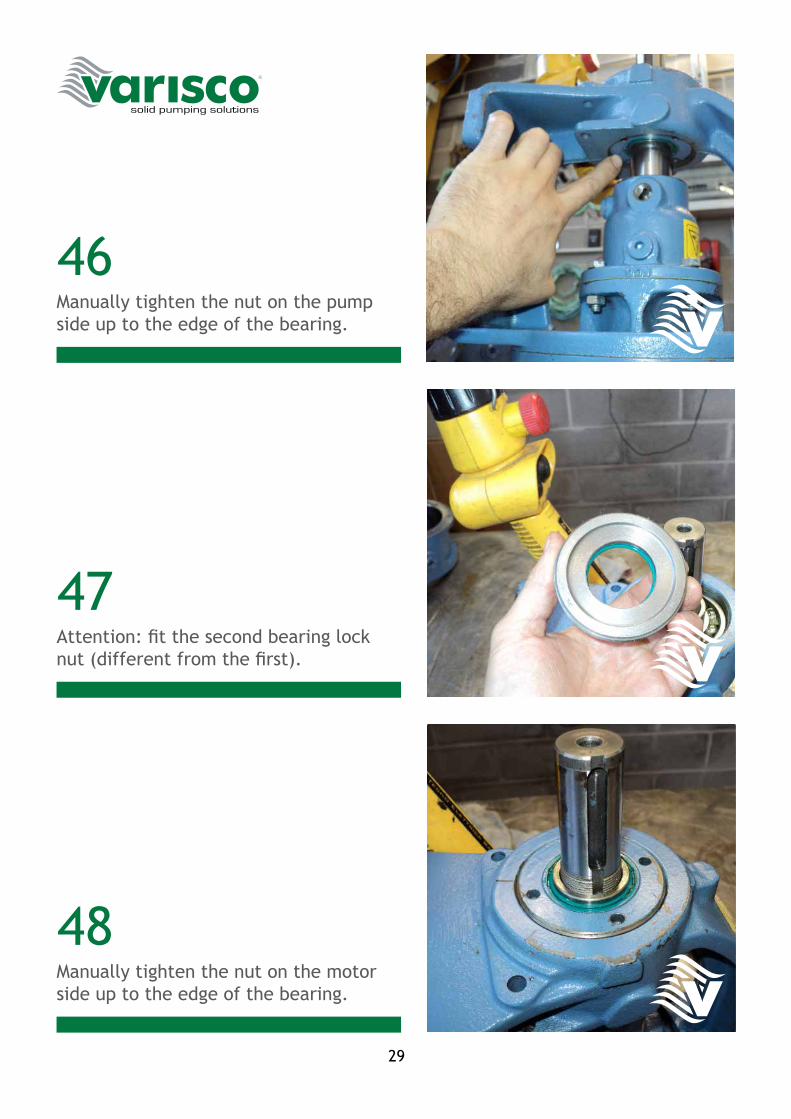
Manually tighten the nut on the pump side up to the edge of the bearing.
Attention: fit the second bearing lock nut (different from the first).
Manually tighten the nut on the motor side up to the edge of the bearing.
30
49
50
51
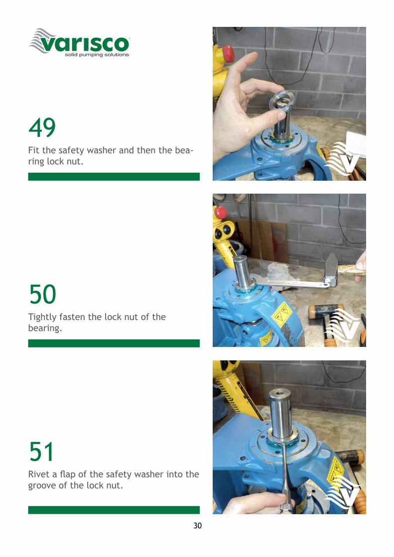
Fit the safety washer and then the bea-ring lock nut.
Tightly fasten the lock nut of the bearing.
Rivet a flap of the safety washer into the groove of the lock nut.
31
52
53
54
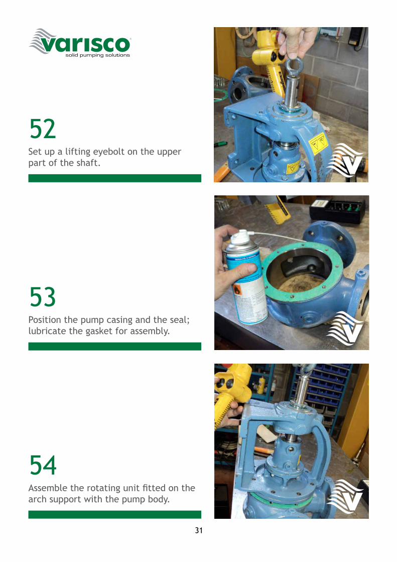
Set up a lifting eyebolt on the upper part of the shaft.
Position the pump casing and the seal; lubricate the gasket for assembly.
Assemble the rotating unit fitted on the arch support with the pump body.
32
55
56
57
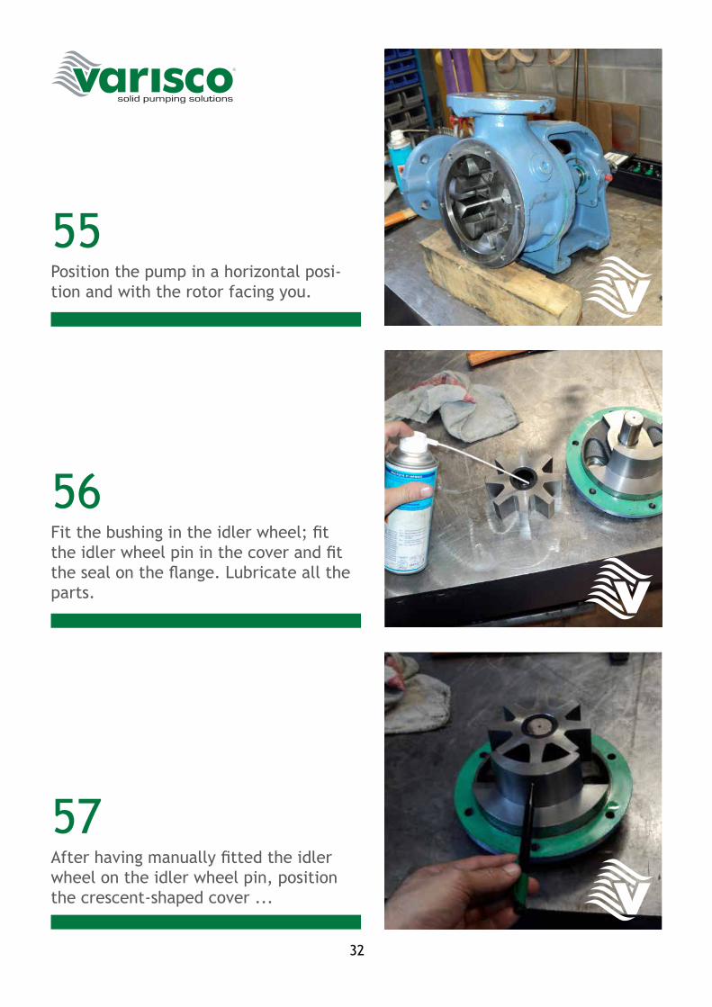
Position the pump in a horizontal posi-tion and with the rotor facing you.
Fit the bushing in the idler wheel; fit the idler wheel pin in the cover and fit the seal on the flange. Lubricate all the parts.
After having manually fitted the idler wheel on the idler wheel pin, position the crescent-shaped cover ...
33
58
59
60
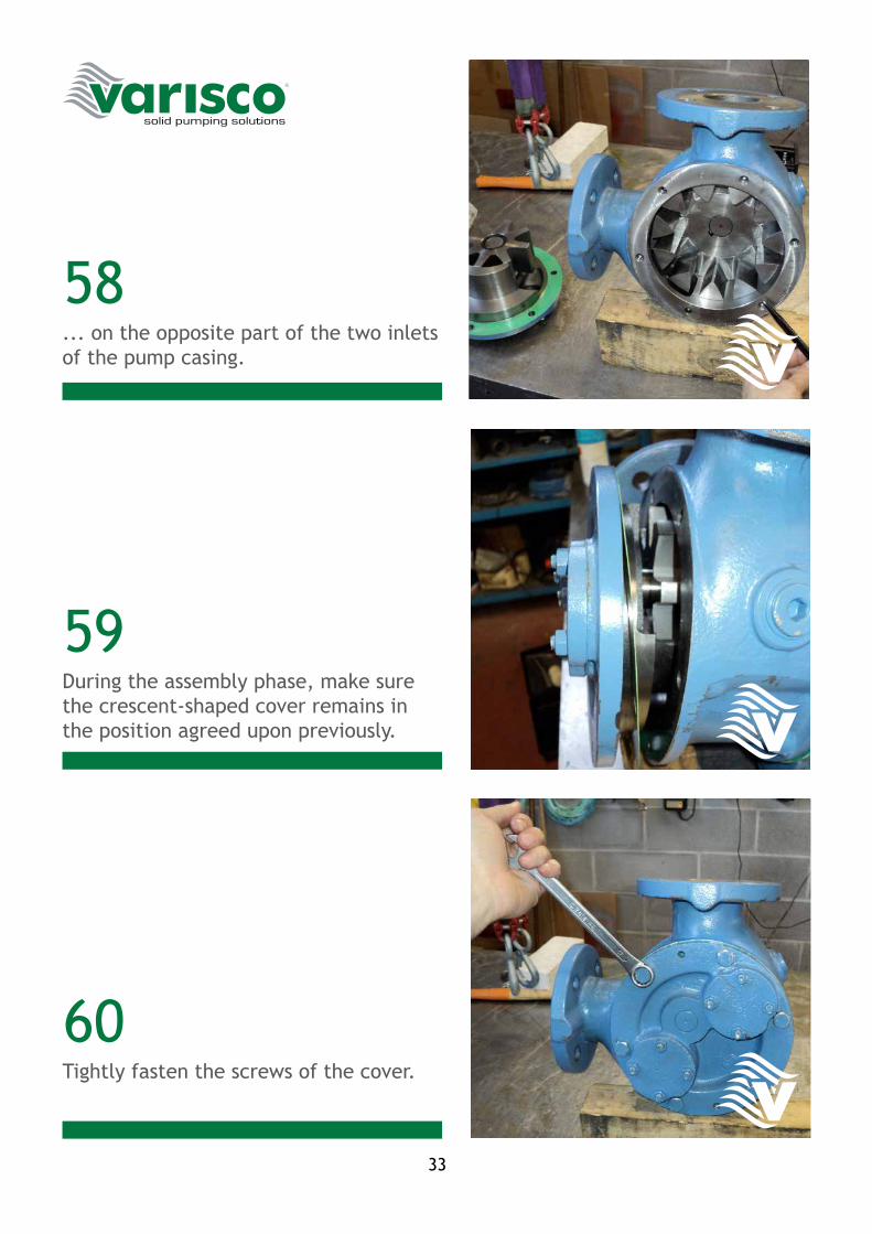
... on the opposite part of the two inlets of the pump casing.
During the assembly phase, make sure the crescent-shaped cover remains in the position agreed upon previously.
Tightly fasten the screws of the cover.
34
61
62
63
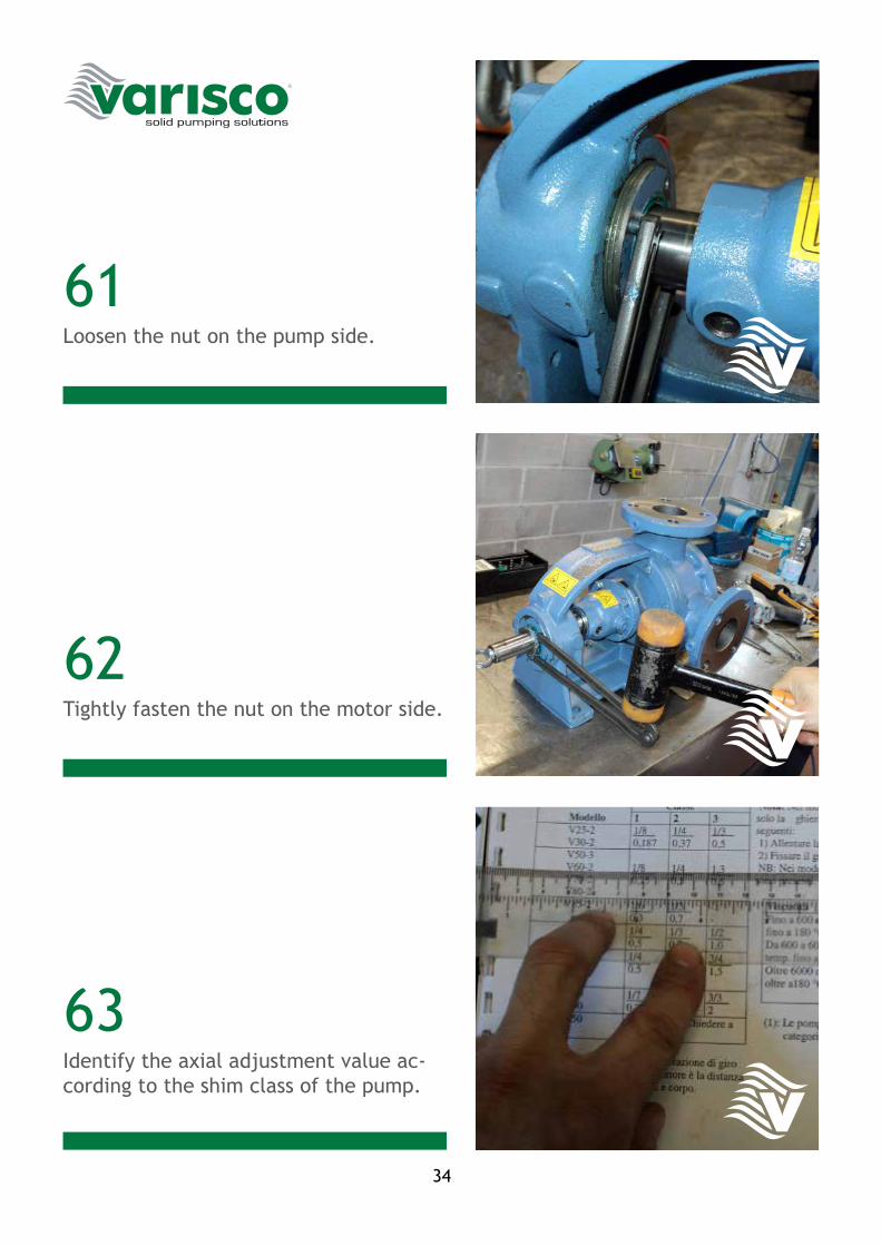
Loosen the nut on the pump side.
Tightly fasten the nut on the motor side.
Identify the axial adjustment value ac-cording to the shim class of the pump.
35
64
65
66
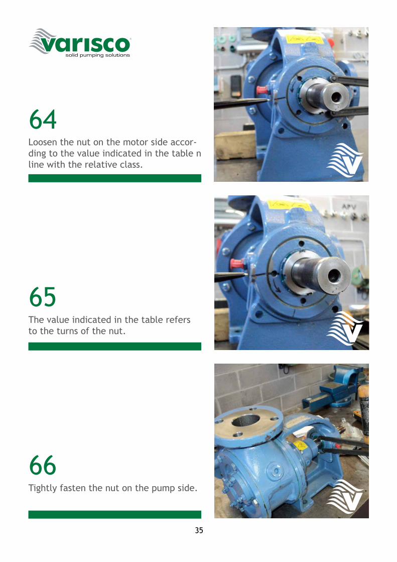
Loosen the nut on the motor side accor-ding to the value indicated in the table n line with the relative class.
The value indicated in the table refers to the turns of the nut.
Tightly fasten the nut on the pump side.
36
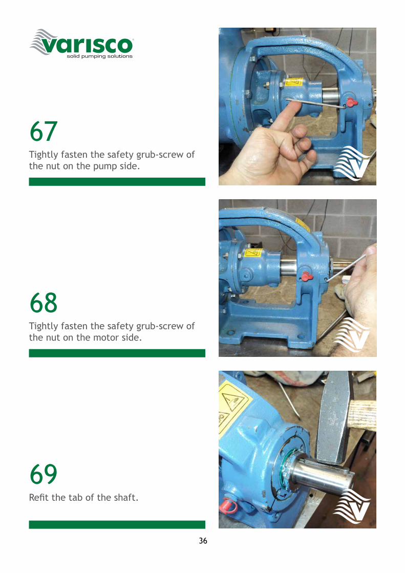
67
68
69
Tightly fasten the safety grub-screw of the nut on the pump side.
Tightly fasten the safety grub-screw of the nut on the motor side.
Refit the tab of the shaft.
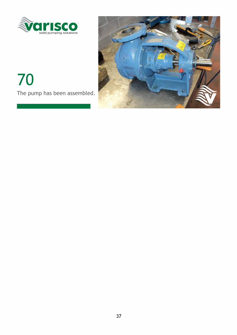
37
70The pump has been assembled.

38

39
40
VARISCO S.p.A. 35129 Padova – Z.I. Nord Terza Strada, 9 Tel. 049 82 94 111 +39 049 82 94 111 Fax 049 82 94 373 International +39 049 80 76 762
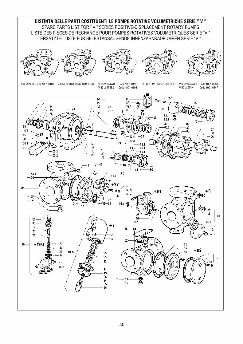
DISTINTA DELLE PARTI COSTITUENTI LE POMPE ROTATIVE VOLUMETRICHE SERIE ” V ” SPARE PARTS LIST FOR ” V ” SERIES POSITIVE-DISPLACEMENT ROTARY PUMPS
LISTE DES PIECES DE RECHANGE POUR POMPES ROTATIVES VOLUMETRIQUES SERIE ”V ” ERSATZTEILLISTE FÜR SELBSTANSAUGENDE INNENZAHNRADPUMPEN SERIE ”V ”
V 60-2 – 0407 – Rev.02
V 60-2 SPG Code 1001 0181
V 60-2 SPHTR Code 1001 0190 V 60-2 ST4WG Code 1001 0198 V 60-2 ST4BS Code 1001 0193
V 60-2 SPK Code 1001 0233
V 60-2 ST4WAT Code 1001 0260 V 60-2 ST4K Code 1001 0247
41

VARISCO S.p.A.P.Iva 00209080282Zona Industriale Nord Terza Strada, 935129 PADOVA - ITALIA
ItaliaTel. +39 049 8294111Fax +39 049 [email protected]
International
Fax +39 049 [email protected]