Embed Size (px)
Citation preview

R Series
Read and understand this manual prior to operating or servicing this product.
Operation and Maintenance Manual
Positive Displacement Pump
Indianapolis ● Chicago ● San Juan www.hollandapt.com
800-800-8464

1
APV Instruction and Parts Manual
“R” Series Rotary Pump
Model Number ______________________ Serial Number ____________________ Order Number ______________________ General Assembly Number _____________ Cover Body Cover Gasket Material
repaP ____ teltuO/telnI ediS ____ slaicepS ____ )dtS( teltuO tnorF ____
)DH( teltuO tnorF ________ Rectangular Inlet Rotor Material ____ Vented
)dtS( rebbuR elirtiN ____ deeF poT ____ rebbuR MDPE ____ gnitareaeD/gnissageD ____
nocleC ____ ssapyB wolF-lluF ____ ____ Solid Epoxy Rotors ____ Solid Metal ____ PPS
seboL fo rebmuN ________ Flush Face Pump Shaft Seal Type
ecaF desseceR ____ )dtS( muucaV erusserP ____ ezisrednU ____
erusserP ____ ezisrevO ____ ____ Single Mechanical Pump Shaft Seal Color Code ____ Water Flush ____ Specials ____ White ____ Blue Hub Materials ____ Red ____ Green ____ Stainless Steel
yxopE ____ egnarO owT ____ Accessory Tools ____ Seal Inserter Assembly 0, 1, 2 ____ Seal Inserter Assembly 3
sA retresnI laeS ____ 2 ,1 ,0 hcnerW rennapS ____ sembly 4, 6, 700 rotoR ytuD-yvaeH ____ 6 ,4 ,3 hcnerW rennapS ____ Puller 4HD, 6HD, 700
dnaH ”T“ – hcnerW tekcoS ____ 0 relluP rotoR ____ le 1, 2 ____ Rotor Puller – Three-Prong 1, 2, 3 ____ Rotor Puller – Solid Plastic Rotor 3, 4, 6 ____ Rotor Puller & Special Wrench 3, 4, 6 Spares & Service Parts Tel: 888-278-4321 / Fax: 888-278-5329 03WP469240 A-1-500-700 (Rev. 8)

2
Table of Contents Introduction 3 Shaft Seal Insertion Procedure 47 94 stfahS dna srotoR Standard Warranty 4 Removing Two-Lobe Rotors (R0 Pump Only) 49
iw srotoR gnivomeR 5 straP ecivreS VPA tuobA droW A th Three-Prong Tool (R1, R2 and R3HD Pumps)
49
Rotor Exchange Program 6 Removing Rotors with Star Wrench 49 Safety Information )spmuP 6R dna 4R ,3R( 7De�nitions 8 Removing Rotors with Heavy-Duty Puller 49 Safety Decals 9 (R4HD, R6HD and R700 Pumps) Electrical Hazard 10 Mechanical Hazard 10 Shaft Wear 50
dnoceR dleiF 11 drazaH lacimehC gnizitinaS/gninaelC 15 gninoitiecnanetniaM evitatneverP 11 drazaH erutarepmeT hgiH Check List 52
High Pressure Hazard 12 Rotary Pump Maintenance Tips 53 Leaking Fluid Hazard 12 Options Important Cautions 13 Vented Cover 54 Corrosion Pitting 45 noitallatsnI dleiF 31Motor Overload 13 Cleaning 54 Cavitation 13 Manual 55 Adjusting Vented Cover – Manual Operation 55 Adjusting Venter Cover – Pneumatic Operation 56 General Information 75 tiK laeS hsulF retaW 41Components and Services Furnished by the Customer 14 Flanged Hopper Rectangular Inlet 58 Sanitary Design 85 gninaelC & noitallatsnI 41Receiving and Inspection 95 rotareaeD – ressageD 41General 15 Product Flow 59 Speci�cations 16 APV O�ces 60
71 serutaeF ngiseD elbaliavA Special Pump Types 18 Service Parts Rotors 19 Model R0 61 Rotor Pullers 46 DH3R dna 3R ,2R ,1R sledoM 62Clearance for Particulates 28 Models R2RI, R3RI and R3HDRI 68
6R dna 4R sledoM 92 noitacifitnedI laeS tfahS pmuP 72 67 IR6R dna IR4R sledoM Installation 18 DH6R dna DH4R sledoM 03Selecting Unit Location 68 IRDH6R ,IRDH4R sledoM 03Gear Case Oil 29 DH007R sledoM 03Rotation Check 79 IRDH007R sledoM 03
13 snoitadnemmoceR tinU evirD Torque Limited Drivers 31 Vented Cover Option Models R1, R2, R2RI, R3, R3RI, R3HD and
R3HDRI 111
Cleaning and Sanitizing 211 IR6R ,6R ,IR4R ,4R sledoM 23Initial Cleaning 32 Cleaning Tips 32 Water Flush Seal Kit
IR2R ,2R ,1R sledoM 23 spmuP 0R rof erudecorP yliaD , R3, R3RI, R3HD, 3HDRI 113 4R sledoM 33 ,DH3R ,3R ,2R ,1R rof erudecorP yliaD , R4RI, R6 and R6RI 114
,IR4R ,4R sledoM spmuP DH6R dna 6R ,DH4R ,4R R6 and R6RI - Top Feed 115 ,DH4R sledoM 43 ,IRDH6R ,IRDH4R rof erudecorP yliaD R6HD and R700HD 116
R700RI, R700HDRI, R4BHDRI, R6BHDRI and Models R700, R700HD Top Feed and R700RI 117 R700BHDRI pumps Shaft Seals Theory of Operation 37 Heavy Duty Cover Seal options 118 021 slaes tfahs dradnatS Operation 38 Rotors 121
83 pmuP eht gnippotS dna gnitratS Tools 126 Maintenance 39 Recommended Inventory 127 Lubrication 39
04 liO gnignahC & gniddA ,gnikcehC Roller Bearing Adjustment (R0 Pump Only) 41 Roller Bearing Adjustment (All Pumps Except R0 Pump ) 42
34 ylbmessasiD )ylnO pmuP 0R( esaC raeG 44 ylbmessA )ylnO pmuP 0R( esaC raeG
Gear Case (All Pumps Except R0 Pump) Disassembly 45 Gear Case (All Pumps Except R0 Pump) Assembly 46 Oil Seal Replacement and Relocation (R0 Pump Only) 47

3
Introduction
Congratulations, you are the owner of a quality built item of APV. This equipment was manufactured by the skilled personnel of a company which has served the needs of the dairy, food and process industries for more than 150 years. The purpose of this manual is to provide instructions for the safe installation, operation and maintenance of your APV equipment. Read and understand the entire manual before removi ng from the crate and installing the equipment. APV is committed to provide quality equipment and customer satisfaction. We have a unique network of sales and service support throughout the world (see the o�ce listing at the back of this manual). Should you have any questions concerning any information contained in this manual, contact the nearest o�ce to you or our Delavan, Wisconsin o�ce for assistance.

4
Standard Warranty
Obligations of Seller During the warranty period, Seller shall repair, or at Seller’s option, replace parts determined by Seller to be defective in material or workmanship. The warranty period is one (1) year from the date of delivery to Buyer F.O.B. point of manufacture. The foregoing shall be the sole obligation of Seller under this warranty with respect to equipment and other property included in this agreement. With respect to equipment, materials, parts and accessories manufactured by others, Seller’s sole obligation shall be to use reasonable e�orts to obtain for Buyer the full bene�t of the manufacturer’s warranties. Warranty Exclusions Repair or replacement of misuse, improper care of storage, negligence, alteration, accident, use of incompatible supplies or lack of speci�ed maintenance are excluded from Seller’s warranty obligations. DISCLAIMER OF WARRANTIES THE FOREGOING WARRANTY EXPRESSIONS ARE IN LIEU OF ALL OTHER WARRANTES, EXPRESSED OR IMPLIED, INCLUDING IMPLIED WARRANTIES OF MERCHANTABILITY AND FITNESS FOR A PARTICULAR PURPOSE, AND EXISTENCE OF ANY SUCH OTHER WARRANTY IS HEREBY DENIED. Limitation of Liability and Remedies The liability of Seller for breach of any warranty obligation hereunder is limited to:
1. The repair or replacement of the equipment on which the liability is based; or, 2. At Seller’s option, the refund to Buyer of the amount paid by Buyer to Seller for
said equipment. All other liability of Seller with respect to this Agreement, or from the manufacture, installation, maintenance, repair or use of any equipment covered by or furnished under this Agreement, whether in contract or in tort, or other wise, is limited to the amount paid by Buyer to Seller pursuant to the terms hereon: SELLER SHALL NOT BE LIABLE FOR INCIDENTAL OR CONSEQUENTIAL DAMAGES OF ANY KIND WHATSOEVER. THE REMEDIES SET FORTH HEREIN ARE EXCLUSIVE. Breach Any breach by Seller with respect to any items or unit of equipment shall be deemed a breach with respect to that item or unit only. Infringement Seller will not be liable for the infringement of any patent by the Buyer’s use of any equipment or materials delivered hereunder. POLICY REGARDING AVAILABILITY OF SERVICE PARTS APV will attempt to remain in a position to supply replaceable service parts during the normal life of any item of APV equipment. This will be contingent upon availability of tools, material, and facilities of our own as well as of our suppliers. After expiration of this period, supply of service parts will be limited to available stock of completed parts. If unable to supply service parts, drawings may be furnished (when available) to permit local manufacturing, if desired. APV reserves the right to improve, change or modify the construction of its equipment or any parts thereof without incurring any obligation to provide like changes to equipment previously sold.

5
A Word About APV Service Parts
We want to raise your awareness to the problem associated with purchase of parts not manufactured to the high quality speci�cations of APV. In addition to our high quality, APV parts are manufactured to meet regulatory agency authorizations, approvals and certi�cation (USDA and OSHA). Where applicable, materials used in construction of APV parts conform to FDA regulations. WARNING PARTS NOT MANUFACTURED TO OUR SPECIFICATIONS MAY CAUSE DAMAGE TO YOUR APV EQUIPMENT AND VOID ALL WARRANTIES. USE OF PARTS THAT DO NOT MEET APV’S SPECIFICATIONS MAY CAUSE PROPERTY DAMAGE AND SERIOUS BODILY INJURY. Types of equipment include, but are not limited to, rotary pumps, centrifugal pumps, homogenizers, scrape surface heat exchangers and plate heat exchangers. We bring this potentially serious problem to your attention in order to safeguard your best interest and those of your employees. If you have any questions, please feel free to call 1-888-278-4321 or your local APV o�ce.

6
Rotor Exchange Program
Obligations of Seller Use our exchange rotor program for R Series pumps and get these bene�ts: - Pump warranty protection - 100% factory inspection of all returned rotors - Fast turnaround direct from stock inventory - Save up to 30% on each reusable rotor - Save 10% on a new rotor if your return rotor is unusable - Original equipment materials and workmanship
Here is how the exchange program works: 1. Each new R Series pump or new service part rotor in sizes R1, R2, R3, R4,
R4HD, R6, R6HD, R6SL, R700 and R700SL will be supplied with a bright green tag and an instruction sheet. (Pump assemblies will have these in the instruction manual.)
2. Should you need to exchange a rotor(s), simply place an order with your local pump distributor, or call toll free 1-888-278-4321 for the location to our nearest distributor. You will be given an RFE number to mark on the green tag. If you do not have a green tag, one will be rushed to you.
3. Follow normal manual cleaning procedures before packing the rotor(s) for shipment.
4. Apply the green sticker (with your assigned number marked on it) to the outside of your shipping package.
5. Ship FREIGHT PREPAID to: APV 611 Sugar Creek RoadDelavan, WI 53115
6. Upon receipt, the rotor(s) will be inspected to ensure that the stainless steel insert (hub) meets speci�cations for proper pump operation. You will be contacted and informed of the condition of your returned rotor(s) and given pricing and delivery information.
And:
a. If the insert (hub) is in usable condition, you will receive the exchange rotor price. (Up to 30% less than the cost of a new rotor.) b. If the insert (hub) is not reusable, you will still receive a 10% discount
on the cost of a new rotor.
Conditions: 1. Rotors Covered: R Series Rotary Pump 5-lobe rotors in sizes R0, R1, R2,
R3, R4, R4HD, R6, R6HD, and R700 with stainless steel inserts (hubs), Nitrile, EPDM and HNBR (rubber) covering, recessed and �ush faces (standard).
2. All rotors submitted will become the property of APV. 3. Rotors must be exchanged for rotors of the same model size.

7
Safety Information
The following information provides speci�c safety information on hazardous conditions, which are inherent in the pump. Safe installation, operation and maintenance require proper training of all personnel and their supervisors. Our objective in providing instructions and warnings is to identify each area of potential hazard and its level of severity and to guide each worker for safe operation, service and maintenance procedures. APV equipment is designed to provide minimum operator access to hazardous areas while providing adequate access for service by trained personnel. Hazardous areas are provided with guards. Various types of fasteners may be used for the guards depending on how frequently routine access is required. Regardless of the type of fastener used, the mere existence of a guard should alert the worker to the presence of a hazard. Never operate or test run the equipment with a guard removed, unless under the supervision of properly trained and authorized personnel. Then use extreme caution to avoid the hazard. Safety Decal Location The following illustrations show the typical location of the safety information decals attached to the pump. If any decal is removed or becomes unreadable, replace it immediately with a new decal.

8
Safety Information
De�nitions DANGER An immediate hazard with a possibility of severe pe rsonal injury or death if instructions, including recommended precautions, are not followed. WARNING Hazards or unsafe practices which could result in severe personal injury or death if instructions, including recommended precautions, are not followed. CAUTION Possible hazards or unsafe practices which could result in minor injury or damage to product or property, if instructions and recommended precautions are not followed. LOCK OUT A positive means of securing the main electrical disconnect in the O� position, where only the person involved in the maintenance procedure has possession of the key.
9
Safety Information
Safety Decals The following decals are attached to each pump. The wording is shown below. If any decal is removed or becomes unreadable, replace immediately with a new decal. Order from APV using the part number shown. Each pump has a tag attached when it is shipped from the factory. The wording of the tag can be read as shown below.

10
Safety Information
Electrical Hazard The pump is normally powered by an electric motor and may have other electronic controls and devices. This creates a hazard of electrical shock, which could cause severe injury or even loss of life. To minimize the risk of this hazard: 1. All electric/electronic installation must comply with all applicable codes
and standards including those established by the Occupational Safety and Health Administration (OSHA) and EC Machinery Directive.
2. All electric/electronic installation, maintenance and service must be
performed by trained and authorized electricians only. 3. Install a main power disconnect On-O� switch that can be locked in the
power O� position and have the key removed. This will allow maintenance or service to be performed with no possibility of the power being accidentally turned on.
4. Thoroughly read the motor manufacturer’s instructions before making
installation. 5. Install an emergency shuto� switch within easy reach of the operator. 6. Make the installation suitable for a wet environment, including:
a. Protection from �ooding. Do not install in an area which could �ll with water to a level which would contact the motor
b. Protection of all electrical connections within a sealed junction box c. Proper grounding
Mechanical Hazard The unit has mechanical drive components. All of these components are guarded and/or enclosed. However, it is necessary to remove the guards/enclosures to perform routine maintenance, cleaning, or service procedures. These components are powered by electric motors, which may start unexpectedly from a remote control signal. Should the unit start unexpectedly during these procedures, severe injury or even loss of life could result. To minimize the risk of this hazard: 1. Only trained and authorized mechanics should perform maintenance or
service work on the unit. 2. Install an emergency shuto� switch within easy reach of the operator.

11
Safety Information
Cleaning/Sanitizing Chemical Hazard To properly clean and sanitize the pump for use with food products, it may be necessary to use chemical solutions. Many of the commonly used chemical solutions could cause severe injury to personnel if contacted. The hazard is especially severe for eyes, skin, or inhalation. To minimize the risk of this hazard: 1. Thoroughly train all personnel working with cleaning/sanitizing chemicals
in their safe handling and disposal following use as required by OSHA’s “Hazardous Materials Standard” and EC Machinery Directive.
Additional precautions are required during the use of cleaning or sanitizing chemical solutions to minimize the risk of personnel contact which could cause an injury. 2. When using manual cleaning methods:
a. Turn o� the power source and Lock Out before disassembling the pumps.
b. Equip all personnel using cleaning/sanitizing solutions with protective clothing including eye protection.
c. Thoroughly train all personnel using cleaning/sanitizing in their safe handling and disposal after use.
d. Never use toxic and/or �ammable solvents for cleaning. High Temperature Hazard When hot products are being processed, or when high temperature cleaning/sanitizing solutions are used, they create a hazard of burns. To minimize the risk of this hazard: 1. All installation, maintenance and service of piping, valves and other
controls must be performed by trained and authorized plumbers only. This applies to service media piping, process piping and cleaning / sanitizing piping.
2. All plumbing installation must comply with all applicable codes and
standards including those established by OSHA and EC Machinery Directive.
3. All high temperature lines must be labeled leak free and insulated or
otherwise protected from direct contact. 4. Never disconnect any lines or �ttings until the line is not under pressure and
the �uid inside is not hot or otherwise harmful. 5. Operating personnel must be authorized and trained.

12
Safety Information
High Pressure Hazard Fluids processed by a pump are under pressure. This creates a hazard to personnel working in the area should a leak occur. Leaking high pressure �uid may cause injury by startling personnel or from actual contact with the leaking �uid. To minimize the risk of this hazard: 1. All installation, maintenance and service of piping, valves and other
controls must be performed by trained and authorized plumbers only. This applies to process piping and cleaning/sanitizing piping.
2. All plumbing installation must comply with all applicable codes and
standards including those established by OSHA and EC Machinery Directive.
3. Never disconnect any lines or �ttings (whether process or
cleaning/sanitizing) or disassemble the pump when lines are under pressure. 4. Should a leak occur, immediately �nd the cause and stop the leak. Leaking Fluid Hazard Fluid leaks or spills may occur in any pumping system. This creates a hazard to personnel in the area due to slippery �oor conditions or contact with possibly hazardous �uids. To minimize the risk of this hazard: 1. Always clean up leaks and spills immediately 2. Find and correct the cause of the leak immediately

13
Important Cautions
The following important cautions describe ways to avoid incorrect operating procedures which will cause serious damage to the pump. Corrosion Pitting Stainless steel is subject to a risk of corrosion when improperly cleaned or sanitized. To minimize this risk: 1. Never use steel wool or a wire brush to clean stainless steel surfaces. Iron
particles will embed and cause corrosion pits. Use a nonmetallic brush or scrub pads for stubborn soil.
2. Never allow prolonged contact of sanitizing solutions or other corrosive
cleaning chemicals with stainless steel. Use sanitizers only immediately prior to processing. Do not use sanitizers on exterior, non-product contact surfaces.
Motor Overload Depending on the rotor diameter and motor horsepower, there is a risk the pump motor will overload if operated with a partially restricted discharge. To minimize this risk of this hazard: Before operating the pump, review performance curve and application giving considerations to motor horsepower and pump model versus expected discharge �ow rate and pressure. If the pump is operated with greater than expected discharge pressure, the load on the motor will increase. Install a throttling type valve in the discharge piping to allow control of pump discharge �ow rate during initial operation. The valve may be removed later when the system is proven to supply adequate discharge pressure to prevent overload. Cavitation Cavitation is a condition within the pump, which results in extreme hydraulic forces which can create a risk of severe damage to pump components. Cavitation makes a characteristic “rattling” noise. It is caused by operation with too low �uid pressure at the pump inlet. To minimize this risk of this hazard: Install and operate the pump so that NPSH (net positive suction head) available to the pump equals or exceeds the NPSH required as shown on the pump performance curve. To increase NPSH available: 1. Decrease the temperature of the liquid being pumped. 2. Increase the height of liquid supply level. 3. Decrease the suction line length and remove restrictions to follow such as
elbows, valves, etc. 4. Increase the suction line size (diameter). 5. Reduce the pump �ow rate (throttle discharge).

14
General Information
Components and Services Furnished by the Customer Installation The installation and start-up of this equipment is solely the responsibility of the purchaser unless speci�cally provided for in the purchase agreement or in a separate contract. Piping All piping is to be supplied and installed by the purchaser. Piping must be well supported near the unit and in line with connection �ttings so that no strain is put on the �ttings. The use of large diameter lines and wide sweep elbows is recommended to keep discharge pressures to a minimum level. Utilities All services for water, vacuum, electricity, air and other connections needed for operation are to be provided by the purchaser. Sanitary Design The materials of construction in product contact areas are stainless steel or other materials approved for food contact. All product contact surfaces must be smooth, free-draining and accessible for cleaning. The mechanical product components must be easy to disassemble for cleaning and/or inspection for cleanliness. The outer construction must prevent outside contaminants for draining or dripping into the product area. Receiving and Inspection 1. APV equipment is inspected prior to shipment. When leaving the factory, it
is well crated for normal transportation procedures. APV cannot, however, guarantee safe arrival. Therefore, upon receipt of this equipment, check the received items against the packing list for damage or missing parts. Check the packing material thoroughly for small parts.
2. Visually inspect for damage or loss. Damage or loss should be reported
immediately to the delivery carrier while present. Following the immediate noti�cation of the lost or damaged parts, a detailed description including quantity, description of the loss or damage, and a cash value should be claimed against the carrier with respect to the guidelines set forth by the responsible carrier’s policies. APV’s responsibility terminates F.O.B point of manufacture unless otherwise speci�ed per the General Terms and Conditions of Sale as published by APV and amended from time to time. Contact APV Order Services if shipping information is required for handling claims.

15
General Information
3. In the case of damage or loss to the equipment, APV may perform three major functions:
a. Manufacturer Function – APV manufactures quality equipment
and stands behind the APV Standard Warranty. Refer to the Standard Warranty.
b. Assessor Function – APV o�ers assessment services for �ling claims. The APV assessor will accurately determine the extent of the damage (or loss) and cost of repairs to the equipment. Reimbursement for this service will be agreed upon prior to the assessment.
c. Repair House Function – APV o�ers services for repairing the damage(s) or replacement of loss(es) to the equipment. APV has the option to alter the Standard Warranty on refurbished or replacement parts. The cost of this service will be dependent upon the assessment that is made.
General APV rotary pumps are known the world over for their rugged, long-lasting, e�cient performance. Every pump in the line has a stainless steel body, applicable rotors and a heavy cast iron gearcase - all of which are designed to give long lasting, economical service over a wide range of products and applications. Shown below, and throughout this manual, are typical pump sizes and design options available for almost any application.

16
General Information Speci�cations
PUMP SIZE R0 R1 R2 R3&R3HD R4&R4HD F6&R6HD R700
psig 100 100 100 ** ** ** ** Maximum Pressure bar 6.9 6.9 6.0 ** ** ** **
US pgm 2.5 6.0 9.0 36 90 150 200 Maximum Capacity m3/hr 0.57 1.37 2.0 8.2 20.4 34.1 45.4
Maximum Speed rpm 600 600 600 600 600 600 400 in3 1.065 2.37 3.54 14.8 40.4 67.2 134.4
cm3 17.5 39 58 234 662 1101 2202 lb.water 0.039 0.085 0.128 0.534 1.46 2.43 4.86
Displacement per Revolution
grams water 17.5 39 58 243 662 1100 2200 in 1.5 1.5 1.5 1.5&2 2&3 2.5&3 4 Inlet & Outlet Connection
Size(s) Standard Body mm 38 38 38 38&51 51&76 64&76 102 in 0.4x0.9 0.75 0.94 1.40&1.87 1.87&2.75 2.37&2.75 2.38&5.38 Throat Size(s)
mm 0.49x0.9 19 24 36&47 47&70 60&70 60&137 in2 0.326 0.442 0.69 1.54&2.75 2.75&5.94 4.41&5.94 11.55 Throat Area
cm2 2.1 2.9 4.5 9.9&18 18&38 28&38 75 in N/A N/A .88x2.5 1.5x4.5 1.75x9.25 3x9.25 6.63x9. 25 Optional Rectangular Inlet Size
mm N/A N/A 22x64 38x114 44x235 76x235 168x235 in2 N/A N/A 2.19 6.75 16.2 27.8 61.3 Optional Rectangular Inlet Area
cm2 N/A N/A 14.1 43.3 103 179 395 in N/A N/A N/A 1.5&2 3 3&4 4 Optional Front Cover Outlet
Connection Size mm N/A N/A N/A 38&51 76 76&102 102 in N/A N/A N/A 1.40 2.37 2.37&2.38+ 2.38+ Throat Size
mm N/A N/A N/A 36 60 60&61 in2 N/A N/A N/A 1.54 4.41 4.41&5.39 5.39 Throat Area
cm2 N/A N/A N/A 9.9 28 28&35 35 BPH 0.5 0.9 1.5 4 8.5 14 20 Maximum Power Requirement kw 0.37 0.67 1.12 3 6.3 10.5 15 lbs 43 45 45 85 195 210 355 Shipping Weight * kg 20 21 21 39 88 95 161
* Shipping weight includes the combined weight of the pump and the shipping crate ** Standard Pump pressure maximum is 100 psig (6.9 bar), Heavy-duty pump pressure maximum is 150 psig (10.35 bar)
Quantity English Unit SI Unit Paramter English Unit SI U nit Parameter English Unit SI Unit
Length 1 ft 3048 meter Volume 1 in3 15.39 cubic cent Pressure 1 in of water
˚ 2.930retem cibuc 3820.3tf 1snotwen 844.4bl 1ecroF F 249.1 pascals
Pressure 1 lb/in3 6895 pascals Velocity 1 ft/sec 30.48 c / ecrof bl 1.ces/tne
/sretem 8403.ces/tf 18.1/)23-F*(=C*23=C*8.1=F*.pmeT sec sq in (psi) 6.894 kilopascals
Absolute Rankine (*R ) Kelvin (*K) Volumetric 1 in3/sec 15.39 cubic cent/sec Energy 1 ft-lb 1.356 joules
Temp. *R=*F+460 *K=*C+273 Flow Rate* 1 in3/min 2731 cubic cent/sec Force 1 lb 4448 newtonsl 1euqroTces/sretil 23.82ces/3tf 18.1/R*=K*K*8.1=R* b force-in 1130 newton-met
1ces/sretil 9951nim/3tf 1seluoj 653.1bl-tf 1ygrenE lb force-ft 1356 newton-met
es/sretil 587.3ces/lag 1sttaw 653.1ces/bl-tf 1rewoP c Absolute 1 lb
ytisocsiVces/sretil 1360.nim/lag 1stawolik 7547ph 1 ** force-sec/foot 3 47.88 pascals/sec
Parameter English Unit SI Unit 1 gal/min .2271 m 3/hour
Length 1 in 2.540 cent Mass 1 lb 453.6 grams 1 ft3 /sec .0929 meter 3/sec
***ytisocsiVmargolik 6354bl 1retem 8403tf 1
1 mile 1.809 kilometers Pressure 1 standard
erehpsomtatnec qs 254.63ni 1aerA
slacsapolik 3.101)isp 7.41(retem qs 9290.3tf 1
CONVERSION FACTORS
*1000 liters = 1 cubic meter
** 1pascal = second = 10 poise
*** 1 square meter/sec = 10,000 strokes
Kinematic
17
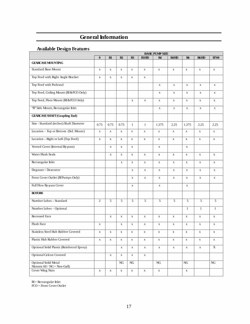
General Information Available Design Features
BASIC PUMP SIZE 0 R1 R2 R3 R3HD R4 R4HD R6 R6HD R700
GEARCASE MOUNTING
Standard Base Mount
x x x x x x x x x x
Top Feed with Right Angle Bracket
x x x x x
Top Feed with Pedestal
x x x x x
Top Feed, Ceiling Mount (RI & FCO Only)
x x x x x
Top Feed, Floor Mount (RI & FCO Only)
x x x x x x x
“B” Side Mount, Rectangular Inlet
x x x x x
GEARCASE SHAFT (Coupling End)
Size - Standard (inches) Shaft Diameter
0.75 0.75 0.75 1 1 1.375 2.25 1.375 2.25 2.25
Location – Top or Bottom (Std. Mount)
x x x x x x x x x x
Location – Right or Left (Top Feed)
x x x x x x x x x x
Vented Cover (Internal By-pass)
x x x x x
Water Flush Seals
x x x x x x x x x
Rectangular Inlet
x x x x x x x x
Degasser / Deaerator
x x x x x x x
Front Cover Outlet (RI Pumps Only)
x x x x x x x
Full Flow By-pass Cover
x x x
ROTORS
Number Lobes – Standard
2 5 5 5 5 5 5 5 5 5
Number Lobes – Optional
1 1 1
Recessed Face
x x x x x x x x x
Flush Face
x x x x x x x x x
Stainless Steel Hub Rubber Covered
x x x x x x x x x x
Plastic Hub Rubber Covered
x x x x x x x x x x
Optional Solid Plastic (Reinforced Epoxy)
x x x x x x x X
Optional Celcon Covered
x x x x
Optional Solid Metal Nitronic 60 / NG = Non-Gall)
NG NG NG NG NG
Cover Wing Nuts
x x x x x x x
RI = Rectangular Inlet FCO = Front Cover Outlet

18
General Information
Special Pump Types R1, R2, R3, R4 and R6 Pumps with Vented Cover Vented cover pumps are designed for use where a pressure release device is needed or where variable back pressures interfere with regulated �ow. The vented cover protects the system against excessive pumping pressures. It is available for either manual or air (pneumatic) operation. The vented cover is not available on the heavy-duty rotary pumps or front cover outlet pumps. Heavy-Duty Pumps Heavy-duty pumps are available in R3, R4, R6 and R7 00 models. They are designed for applications where long discharge lines and/or viscous products combine to create high head pressures. These pumps are equipped with external outboard bearings to prevent shaft de�ections and minimize shaft, rotor and seal wear. Heavy-duty pumps are recommended for discharge pressures between 100 and 150 PSIG (7 and 11 kg/cm2). Front Outlet Cover Pumps The front outlet cover (available on rectangular inlet pumps in sizes R2, R3, R3HD, R4, R4HD, R6, R6HD and R700) enables lowest possible pump installation next to �oor. This is important for hopper pumps which must receive product from low dump heights. Viscous and/or high pressure applications may cause excessive rotor/body wear. Contact an APV o�ce for consultation. Round Inlet Top Feed Pump The top feed pump (available in all sizes) has been designed to pump the more viscous and di�cult to move products. A direct vertical downward entrance to the pump is the main factor in the success of this pump in handling such products. Rectangular Inlet Top Feed Pump The rectangular inlet top feed pump (available in R2, R3, R4, R6 and R700 sizes) has been designed to supplement the top feed pump and the handling of di�cult to move product. The large inlet assures entrance into the pump of a wide variety of products usually considered impossible to pump and also minimizes objectionable air inclusion in the product.

19
General Information
Rotors APV o�ers �ve basic types of rotors for use in rotary pumps. The standard type has a stainless steel hub and rubber covering. Optional types are: epoxy hub rubber covered, solid epoxy, celcon with stainless steel hub, and solid non-galling metal rotors. Additional options are available within the various basic model types – options such as face con�guration and undersize for high temperature operation. Rotor Identi�cation The basic rotor types are easy to identify from the descriptions that follow. Various codes may appear on the rotor hub. One four digit code (for example: 1025) identi�es whether the rotor is undersize for high temperature operation. Solid Epoxy hub rubber covered rotors have a letter etched into the hub area to designate the rubber covering material. “N” for example, designates Nitrile rubber. In addition, stainless steel hub rubber covered rotors have a manufacturing code (for factory identi�cation purposes) consisting of a single digit, followed by a letter (month), then three more digits (day & year). A similar code is used for plastic hub rotors. Stainless Steel Hub-Rubber Covered This is the standard rotor. The long time standard rotor design is a stainless steel hub with a Nitrile rubber covering. This rotor is available with the normal recessed face or with a �ush face and as undersized rotors for high temperature operation. We also have oversize available for low temperatures. All rotors, except the R0 size, have 5 lobes; the R0 size has 2 lobes and an optional 5 lobe design. An optional single lobe rotor is available for R6 and R700 size pumps. Standard Recessed Face & Flush Face The standard rotor con�guration is the recessed face. The recessed face has the least amount of rubber surface contacting the pump cover and body, therefore, the least friction/wear in this area. In addition, the recessed area admits product into the rotor face area. Product in the recess area may further lubricate the rotors, especially if the product does not contain fats or oils. Flush face rotors exclude product, as far as possible, from the rotor face area. This reduces friction/wear when product is abrasive or contains abrasive particles such as berry seeds (�ush face rotors are recommended for these applications). Flush face rotors are also required with the degassing/deaerating front cover outlet pumps.
20
General Information
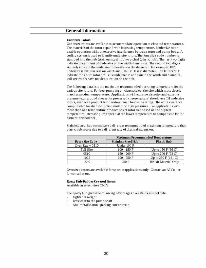
Undersize Rotors Undersize rotors are available to accommodate operation at elevated temperatures. The materials of the rotor expand with increasing temperature. Undersize rotors enable operation without excessive interference between rotor and pump body. A coding system is used to identify undersize rotors. The four digit code number is stamped into the hub (stainless steel hub) or etched (plastic hub). The �rst two digits indicate the amount of undersize on the width dimension. The second two digits similarly indicate the undersize dimension on the diameter. For example: 1025 undersize is 0.010 in. less on width and 0.025 in. less in diameter. The letters “TH” indicate the entire rotor pro�le is undersize in addition to the width and diameter. Full size rotors have no identi�cation on the hub. The following data lists the maximum recommended operating temperature for the various size rotors. For best pumping e�ciency, select the size which most closely matches product temperature. Applications with extreme viscosity and extreme pressure (e.g., ground cheese for processed cheese system) should use TH undersize rotors, even with product temperature much below the rating. The extra clearance compensates for shaft de�ection under the high pressures. For applications with more than one temperature product, select rotor size based on the highest temperature. Increase pump speed at the lower temperature to compensate for the extra rotor clearance. Stainless steel hub rotors have a di�erent recommended maximum temperature than plastic hub rotors due to a di�erent rate of thermal expansion.
Maximum Recommended Temperature Rotor Size Code Stainless Steel Hub Plastic Hub
F 001 rednU 0150 + eziS revO )C 66( F 051 ot pU F 051 - 001 eziS lluF )C 39( F 002 ot pU F 002 - 051 0150 )C 121( F 052 ot pU F 052 - 002 5201 ylnO lairetaM RBNH F 052 0451
Oversized rotors are available for speci�c applications only. Contact an APV o�ce for consultation. Epoxy Hub-Rubber Covered Rotors Available in select sizes ONLY. The epoxy hub gives the following advantages over stainless steel hubs. - Lighter in weight - Less wear to the pump shaft - Non-metallic, non-sparking construction

21
General Information
The reinforced epoxy hub material is not as strong as stainless steel hubs. Therefore, it is recommended they not be used for extreme viscosity applications such as those requiring auger feed pumps, or for pressures over 100 psi (7.0 kg/cm2). The following information details the construction and application limitations of plastic hub rotors. Construction Hub – The Hub is CREPAKYLAN 461 Fiberglass reinforced epoxy. This material is very strong and wear resistant. It meets all requirements of FDA, USDA, 3-A and BISSC for materials in contact with food products. Covering – The Nitrile rubber covering formula used for plastic hub rotors is the same as the current standard stainless steel hub rotors. Excellent bonding between hub and rubber is also achieved. Better dimensional integrity is assured due to more uniform rate of thermal expansion between hub and rotor. The epoxy formula meets all requirements of FDA, USDA, 3-A and BISSC for materials in contact with food products. The appearance is less shiny than previous Nitrile covered stainless steel hub rotors. Alternate Covering Materials – The plastic hub can also be coated with covering materials. Contact an APV o�ce for further details. Application Recommendations Pressure: Recommended for up to 100 psi (7.0 kg/cm2) Temperature: Recommended for product temperatures up to 250 F
(121 C maximum) Solid Epoxy Rotors
Material – the solid epoxy rotor is made entirely from CREPAKYLAN 461 Fiberglass reinforced epoxy. This material is very strong and wear resistant. It meets all requirements of FDA, USDA, 3-A and BISSC for materials in contact with food products. The following list shows typical chemical compatibility of this material.
22
General Information
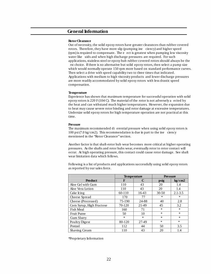
Rotor Clearance Out of necessity, the solid epoxy rotors have greater clearances than rubber covered rotors. Therefore, they have more slip (pumping ine�ciency) and higher speed (rpm) is required to compensate. The e�ect is greatest when pumping low viscosity water like �uids and when high discharge pressures are required. For such applications, stainless steel or epoxy hub rubber covered rotors should always be the �rst choice. If there is no alternative but solid epoxy rotors, then select a pump size which would normally operate 150 rpm more based on standard performance curves. Then select a drive with speed capability two to three times that indicated. Applications with medium to high viscosity products and lower discharge pressures are more readily accommodated by solid epoxy rotors with less drastic speed compensation. Temperature Experience has shown that maximum temperature for successful operation with solid epoxy rotors is 220 F (104 C). The material of the rotor is not adversely a�ected by the heat and can withstand much higher temperatures. However, the expansion due to heat may cause severe rotor binding and rotor damage at excessive temperatures. Undersize solid epoxy rotors for high temperature operation are not practical at this time. Pressure The maximum recommended di�erential pressure when using solid epoxy rotors is 100 psi (7.0 kg/cm2). This recommendation is due in part to the ine�ciency mentioned in the “Rotor Clearance” section. Another factor is that shaft-rotor hub wear becomes more critical at higher operating pressures. As the shafts and rotor hubs wear, eventually rotor to rotor contact will occur. At high operating pressure, this contact could cause rotor damage. See shaft wear limitation data which follows. Following is a list of products and applications successfully using solid epoxy rotors as reported by our sales force.
Temperature Pressure Product F C psig kg/cm2 Aloe Gel with Gum 110 43 20 1.4 Aloe Vera Lotion 110 43 20 1.4 Cake Icing 60-110 16-43 30-50 2.1-3.5 Cheese Spread 170 77 * * Cheese (Processed) 75-190 24-88 40 2.8 Corn Syrup, High Fructose 70-120 21-49 45 3.2
* * 17 061 laeM hsiF * * 01 05 eeruP tiurF * * * * yrrulS muG
Poultry Digest 80-120 27-49 * * 5.3 05 44 211 lezterP
Shaving Cream 110 43 20 1.4 *Proprietary Information

23
General Information
Certain products have demonstrated that they cannot be pumped successfully using solid epoxy rotors. One such is tomato base products, such as spaghetti sauce, pizza sauce, tomato juice or tomato soup. Tomato base products cause an excessive rate of wear, especially at higher temperatures. Another troublesome product group is extreme viscosity non-�uid products such as commonly handled by auger feed pumps. In part, the problem here is the very high discharge pressures normally encountered. In addition these type of products tend to resist �owing out of the area where the rotors are meshing together causing interference and rotor damage results. Products in this category include ground meat, ground cheese and dry dough preparations such as; pie dough, masa dough and rotary cut cooked dough. Chemical Compatibility CREPAKYLAN 461 (solid epoxy) has good chemical resistance and is fully resistant to most common food related products, cleaning agents and sanitizers. It is also resistant to most industrial chemicals. An exception is certain strong solvents which attack the material. These strong solvents are by nature very low viscosity and therefore, in the pure state, better suited for centrifugal pumps. Potential misapplication is most likely to occur when these solvents are a signi�cant percentage of other more viscous products requiring a positive type pump. Following is a partial list of compatible (C) and not recommended (NR) chemicals for use with CREPAKYLAN 461 material:
%3-0 ,edixoreP negordyH C F 001 ,0/05 ,dicA citecA , 150 F C C F 002 ,dicA ciruaL RN F 051 ,%5-0 ,enotecA C F 012 ,liO deesniL C %001-5 ,enotecA C F 051 ,dicA cielaM C F 051 ,slohoclA C F 051 ,dicA ecilaM C F 012 ,reeB C F 051 ,%01-0 lonahteM C F 001 ,enezneB C F 57 ,enoteK lyhtE lyhteM C F 002 ,dicA ciozneB C F 012 ,liO lareniM C edirolhC lyzneB C F 002 ,dicA cielO RN F 012 ,dicA ciroB C F 051 ,lonehP C F 012 ,enirB RN %001-57 ,dicA cirohpsohP C F 001 ,eneidatuB
54-0 ,edixordyH muissatoP C F 01 ,edirolhC muiclaC %, 210 F C C F 012 ,etartiN muissatoP C ediflusiD nobraC
dirolhciD enelyporP RN F 001 ,edirolhcarteT nobraC RN e C F 012 ,paoS C F 002 ,liO rotsaC C F 012 ,etanobraC muidoS C F 012 ,dicA cirtiC
F 012 ,%05-0 ,edixordyH muidoS C 081 ,liO tunocoC C C F 012 ,etartiN muidoS C F 012 ,liO nroC
F 57 ,edixoreP muidoS C F 051 ,cinagrO stnegreteD C ,etaciliS muidoS C F 012 ,detanofluS – stnegreteD C F 051
C F 051 ,dicA ciraetS C F 051 ,etatecA lyhtE C F 001 ,%05-0 ,dicA cirufluS C enimA enelyhtE C F 002 ,dicA cinnaT RN F 012 ,locylG enelyhtE
C F 012 ,dicA ciratraT C F 081 ,sretsE sdicA yttaF C F 051 ,%001 ,eneuloT C F 012 ,sdicA yttaF
01 ,enelyhteorolhcirT C F 002 ,%04-0 ,edyhedlamroF 0%, 150 F C C F 002 ,liO gnuT C F 001 ,%52-0 ,dicA cimroF C F 051 ,aerU C F 07 ,larufruF C F 051 ,rageniV C F 012 ,esoculG C F 051 ,etatecA lyniV C F 012 ,nirecylG C F 012 ,dellitsiD - retaW C F 051 ,enatpeH C F 012 ,aeS - retaW C F 57 ,enaxeH C F 051 ,enelvX C F 081 ,%01-0 ,dicA cirolhcordyH
24
General Information
Celcon Rotors Celcon rotors are available for pump model sizes R1, R2 and R3. They are available with a 316 SS hub and all have �ush face con�guration. They are available in “normal” size for up to 135 F (57 C) service and 05 10 undersize for up to 180 F (82 C) service. Material – Celcon is a registered trademark of the Celanese Corporations. It is an acetal copolymer thermoplastic which is stable in a wide variety of chemicals. It is a white, translucent plastic material which is approved for use in contact with food products by 3-A, FDA and USDA. Celcon is a natural bearing material, having a very low coe�cient or friction against metals. It also has excellent abrasion resistance, good toughness and excellent retention of mechanical properties in various environments. The accompanying information lists chemical compatibility and physical properties. Application – Due to the rigid nature of this material, there is more clearance than with standard rubber covered rotors. However, there is less than with solid epoxy or solid metal rotors. Pump speed must be compensated for slip (as described for solid epoxy rotors), but to a lesser degree. The maximum recommended di�erential pressure for Celcon rotors is 100 psi (7.0 kg/cm 2). Chemical Resistance. Celcon rotors are generally recommended for the following applications: - long term hot water exposure - solvents (acetone & alcohols) - petroleum oils - strong alkalis (caustic) They are not recommended for the following applications. - strong mineral acids (sulphuric, nitric, hydrochloric) - strong oxidizing agents (hypochlorites)

25
General Information Speci�c Products Speci�c Products
RN dicA cielO B %01 – dicA citecA RN dicA cilaxO B enotecA
niffaraP A slohoclA A A enelyhterolhcreP A enirB A ylleJ muelorteP A edirolhcarteT nobraC
lonehP A citsuaC NR B %3 ot – dicA cirohpsohP A %001 ot dicA cirtiC
%01 – etanagnamreP muissatoP A F 081 ot stnegreteD A paoS A sliO elbidE A
edixordyH muidoS A %69 – lohoclA lyhtE A F 37 ot 21 A etatecA lyhtE A F 081 ot 6 B %05 – locylG enelyhtE A %05 – etanobraciB muidoS RN dicA cimroF A %09 ot edirolhC muidoS A esaerG RN etirolhcopyH muidoS A enaxeH RN dicA cirufluS RN %001 – setirilhcopyH
eneuloT RN %2 evoba – dicA cirolhcordyH A B enelyhterolhcirT A lohoclA lyporposI A enilesaV A edixoreP negordyH A sliO elbategeV B %01 – dicA citcaL
rageniV A %01 – edixordyH muisengaM B retaW B etatecA lyhteM A
xaW B enotoeK lyhtE lyhteM A A kliM RN dicA cirtiN
A = Recommended, no change in properties B = Recommended, slight discoloration NR = Not recommended Shaft Wear : An important limitation of solid epoxy or plastic hub rotors is that they not be used in pumps with excess shaft wear. The following illustration and data gives wear limitations for use of these rotors.
Dim. A Dim. B
Pump Size in. mm in. mm
R1, R2 0.824 20.9 ¼ 6 R2.5, R3 0.996 25.3 ¼ 6 R4, R6, R700 1.745 44.3 3/8 10
When checking for shaft wear, measure no further in than the B dimension. If there is wear, it will be near the corners of the shaft.

26
General Information
Minimum Shaft Wear Physical Properties of Celcon:
ASTM Test Property Method Units Temp. Value Speci�c Gravity D792 -- 73 1,410 Tensile Strength D638 psi 73 8,800 Elongation D638 % 73 60. Tensile Modulus D638 psi -- 410,000 Flexural Modulus D790 psi 73 375,000 Flexural Stress D790 psi -- 13,000 (5% Deformation) Compressive Stress D695 psi -- 4,500 Izod Notched D256 ft lb/in 73 1.3 (Impact Strength) Water Absorption D570 % 73 0.22 (24 Hour Immersion) Coe�cient of D1894 -- -- 0.15 Dynamic Friction vs. 0.35 Steel vs. Celcon
Solid SS Metal Rotors Material – The material of the solid metal rotor is a non-galling sanitary SS alloy. Solid metal SS rotors are available for the R2, R3, R4 and R6 is non-galling alloy stainless steel. Wear rings are required for the faces of solid metal rotors to keep them from contacting the pump cover or body during operation. Standard materials for wear rings are a PPS (Ryton) material and a Teflon material which are approved for food product applications. Non-galling SS wear rings for more aggressive duties are also available. Rotor Clearance – As with the solid epoxy rotors, the solid metal rotors have greater clearances than rubber covered rotors. Consequently, their use is primarily intended for products with substantial viscosity. If low viscosity, water like products is pumped, higher rpm will be required to compensate, or discharge pressure will be limited. Torque Limited Drives – Some type of torque limiting drive or drive coupling is recommended when using solid metal rotors. Should a solid piece of foreign metal pass through the pump, it could jam between the rotors. A correctly sized torque limiting device will protect the pump shafts from damage in the event of a jam. Rotor Pullers Several rotor puller tools are available for the various sizes and types of rotors. These tools are illustrated in the Service Parts section of this manual. A pliers type and a three prong type is available for sizes R0 through R3 rubber or Celcon covered rotors. These pullers grip the outside contour of the rotor. A locking pliers type with soft covered jaws is available for solid plastic rotors. This type is available for R3 through R6 sizes. This puller also grips the outside contour of the rotor.

27
General Information A special 4-way (star) wrench is available for R3 through R6 sizes. One end of this puller engages grooves machined inside the square hole of stainless steel hub rotor (this puller will not work with heavy-duty model pumps). A heavy-duty puller tool is available for R4 through R700 size pumps. This tool also engages a groove machined into the square hole of stainless steel hub rotors or solid metal rotors. These grooves are di�erent from the grooves for the 4-way wrench mentioned above. The heavy-duty puller is the only tool which may be used with R4HD, R6HD or R700 size pumps. This puller is recommended when product conditions make rotor removal di�cult with the 4-way puller tool. These rotors have the heavy-duty grooves on one side and the grooves for the 4-way wrench on the other. Care must be used when assembling these rotors so that the correct groove is located toward the pump cover.
Rotor Pullers Part No. Use with Rotor Type
RO size (pliers type) M03A-P-367535 SS hub rubber covered
R1 or R2 (3-prong type) M03A-P-188155 SS hub rubber or Celcon
covered or plastic hub rubber
R2.5 or R3 (3-prong type) M03A-P-225667 SS hub rubb er or Celcon
covered or plastic hub rubber covered
R3 (locking pliers type) M03A-P-395466 solid plastic
R3 (special 4-way wrench) M03H-P-133586 SS. hub rubber or Celcon covered
R4 or R6 (locking pliers type) M03A-P-385820 plasti c hub rubber covered or
solid plastic
R4 of R6 (special 4-way wrench M03H-P-133613 SS. hub rubber covered
R4HD or R6HD (heavy-duty puller) M03A-P-250898 heavy-duty SS hub rubber
covered or solid metal
R700 (heavy-duty puller) M03A-P-221079 heavy-duty SS. hub rubber
covered or solid metal

28
General Information Clearance for Particulates The following data gives dimensions critical to the pumping of particulates through rotary pumps. The maximum recommended particulate size in either a spherical or cube shape is also listed. This does not mean that all particulates under the size limit may be successfully pumped without damage to the particulate or the pump. Other factors which must be considered are: - Particulates must be in suspension. The carrier liquid must prevent the
particulates from sticking together and disturbing the pumping performance. - The carrier liquid must have su�cient viscosity to keep the particulates
moving into the pump inlet. For example, whole kernel corn in water will not pump, as the corn bridges at the inlet and the water is pumped away.
- Use a top feed, rectangular pump whenever possible. - As a general rule, use a large pump with a large inlet size to enable a
relatively slow pump speed. - Avoid very hard particulates which could wedge between rotor lobes and
cause rotor damage.
Maximum Particle
Pump Model
A
(Pocket)
B
(Rotor Width)
C
(Inlet/Outlet) Sphere
Diameter Cube Size
R0 0.206 in. 0.787 in. 0.40 in. 3/16 in. 3/32 in. 0.511 in. 0.558 in. 0.37 in. 11/32 in. 3/16 in. 0.511 in. 0.836 in. 0.44 in. 7/16 in. ¼ in. 0.667 in. 1.001 in. 0.48 in. 15/32 in. ¼ in. 0.667 in. 2.001 in. 1.378 in. 21/32 in. 3/8 in. R1 0.511 in. 0.558 in. 0.750 in. ½ in. 9/32 in. R2 0.511 in. 0.836 in. 0.937 in. ½ in. 9/32 in. R3 0.667 in. 2.005 in. 1.402/1.870 21/32 in. 3/8 in. R4 1.000 in. 2.405 in. 1.870/2.750 1 in. 9/16 in. R6 1.000 in. 4.005 in. 2.370/2.750 1 in. 9/16 in. R700 1.000 in. 8.005 in. 2.375 in. 1 in. 9/16 in. R0 5.23 mm 20.0 mm 10.2 mm 5 mm 3 mm 13.0 mm 14.2 mm 9.4 mm 9 mm 5 mm 13.0 mm 21.2 mm 11.1 mm 11 mm 6 mm 17.0 mm 25.4 mm 12.3 mm 12 mm 7 mm 17.0 mm 50.8 mm 35.0 mm 17 mm 10 mm R1 13.0 mm 14.2 mm 19.1 mm 13 mm 7 mm R2 13.0 mm 21.2 mm 23.8 mm 13 mm 7 mm R3 17.0 mm 50.9 mm 35.6/47.5 17 mm 10 mm R4 25.4 mm 61.1 mm 47.5/69.9 25 mm 14 mm R6 25.4 mm 101.7 mm 60.2/69.9 25 mm 14 mm R700 25.4 mm 203.3 mm 60.3 mm 25 mm 14 mm

29
General Information
Pump Shaft Seal Identi�cation
Pressure Vacuum Pressure Seal Pressure Vacuum Pump No. Color Code Seal (100 psig max.) (150 psig max.) * Heavy-Duty
A/N 350133-P-H30M eulB 0R A/N 350133-P-H30M deR A/N 350133-P-H30M egnarO owT
R1, R2 Green M03H-P-151261 M03H-P-171623 N/A Blue M03H-P-203251 M03H-P-203261 N/A Red M03H-P-203252 M03H-P-203262 M03HP411845 Two Orange M03H-P-203253 M03H-P-203263 M03HP411046
R3 Green M03H-P-149531 M03H-P-203460 N/A Blue M03H-P-203231 M03H-P-203241 N/A Red M03H-P-203232 M03H-P-203242 M03HP411050 Two Orange M03H-P-203233 M03H-P-203243 M03HP411051
R4, R6 & R700 Green M03H-P-149370 M03H-P-171624 N/A Blue M03H-P-203211 M03H-P-203221 M03HP411057 Red M03H-P-203212 M03H-P-203222 M03HP411055 Two Orange M03H-P-203213 M03H-P-203223 M03HP411056
*Not to be used in a vacuum condition. Recommended Compound Usage Of: 1. Red Dot Code – Nitrile (Buna-N) – Furnished as stan dard for all applications or
when product is highly corrosive. Temperature range: -40 to 250 F (-40 to 121 C).
2. Two Orange Dots Code – EPDM (Ethylene-Propylene) – For beverage syrups,
especially diet types and any product containing acetic acid (vinegar). Use with steam and hot water. Temperature range: -40 to 300 F (-40 to 149 C).
3. Blue Dot Code – Fluorocarbon (Viton*) – For highly corrosive products:
Temperature range: 0 to 350 F (-18 to 177 C).
4. Green Dot Code – (Neoprene) – For use with low aniline point oils and certain other products where red dot seals prove unsatisfactory. Temperature range: -50 to 250 F (-46 to 121 C).
*Viton and Neoprene are registered trademarks of E. I. DuPont DeNemours & Company

30
Installation Selecting Unit Location When installing the unit, consider these items before locating: 1. Install the unit in a location with good lighting and clearance around it for
maintenance and operation.
2. Locate with consideration for required service connections. Keep service supply lines as short and direct as possible for optimum operating e�ciency.
3. Locate close to associated process equipment to minimize piping between
equipment and minimize pressure build up through lines. Make sure the piping to and from the pump is correctly arranged and properly supported so that there will be no unnecessary strain on pump parts.
4. Locate near �oor drains with a hose station nearby. Gearcase Oil Refer to the Maintenance Section for recommended amount and type of oil. Rotation Check The rotary pump can be operated in either direction as determined by the desired inlet and discharge locations. Discharge will be on the right when the top rotor turns clockwise and on the left when it turns counterclockwise. Disassemble pump before checking rotation. The two seal pressure relief grooves, one in the upper pump cover and one in the pump body, must always be on the discharge side of the pump. The side of the pump body is clearly stamped “IN” to help determine their correct positions. An oversized stud hole and special large hex stud allow for mounting of the pump body and pump cover in the correct position every t ime. Unless otherwise speci�ed, the pump will always come with the hex shaped stud in the upper left hand position, looking at the front of the pump. Discharge must be taken o� the right. If discharge on the left is desired, the hex stud must be interchanged with the corresponding lower right hand stud. Studs are most e�ectively gripped for removal and installation by tightening two nuts together on the outer thread or by using a wrench on the hex.

31
Installation Drive Unit Recommendations 1. The Versatility and expanded use of APV pumps utilizes a variety of drives for
these pumps. There are many drive units available such as multi-speed, hydraulic and air motor, V-belt and torque limited. Consult your APV representative for type and availability of desired drive.
2. When installing pumps with any of these drive units, it is most important that
proper alignment be maintained between the shaft of the driven pump and the driving unit. This is absolutely necessary to achieve optimum pump performance and maximum service life.
When installing the V-belt sheaves and chain sprockets on the shafts, always install them as close to the gearbox as possible. Torque Limited Drives Use of a torque limited drive or drive coupling is recommended when using solid plastic or solid metal rotors. If a solid piece of foreign material passes through the pump, it could jam between the rotors and cause extensive damage. A correctly sized torque limiting device will protect the pump shafts from damage in the event of a jam.

32
Cleaning and Sanitizing Initial Cleaning Prior to using any rotary pump for the �rst time, disassemble and hand clean the pump. Clean all inner and outer surfaces to remove any dirt, grit or �lm that may have accumulated during shipment and installation. Cleaning Tips 1. Do Not use carbon steel wool. Particles may break o� and become embedded,
causing rust development. 2. Do Not use water high in iron, salt or sulfur. Use distilled water if possible. 3. Do Not allow cleaners or bactericides to remain on surface for over 15 minutes. 4. Rinse all parts and surfaces exposed to corrosive cleaning solutions completely
with cold water. 5. Do Not allow tools or other metal items to lie on wet stainless steel. 6. Only use recommended cleaners. Alkaline dairy cleaners or bactericides should
contain a wetting agent and polyphosphate to suit water hardness. 7. If rust or discoloration occurs, polish the a�ected area immediately to prevent
the condition from progressing. This can be done in most cases by using a damp cloth and a commercial scouring powder.
Daily Procedure for R0 Pump 1. Place a rubber mat under the immediate area of the pump to protect parts which
may drop accidentally. 2. Remove the four hex nuts, cover and O-ring from the pump body. 3. Remove the two rotors from the pump shafts. 4. Install the O-ring, cover and the four hex nuts on the pump body. Tighten the
hex nuts. Do Not �nger tighten. 5. Rinse the outer areas of the pump and gearcase (hand clean if necessary),
according to standard plant procedure. For CIP cleaning, add su�cient cleaner to maintain a 1% causticity for the duration of the cleaning cycle. Do Not leave the rotors in the pump while cleaning the system.
6. When CIP of the system is completed, remove the four hex nuts, cover and O-ring from the pump body. Inspect the O-ring and re place if necessary.
7. Remove the pump body, O-ring and back plate from the gearcase. Inspect the O-ring and replace if necessary.
8. Remove the two shaft seals from the back plate. Inspect the shaft seals and replace if necessary.
9. Remove the two seal bearings and O-rings. Inspect the O-rings and replace if necessary.
10. While the pump is disassembled, check the gearcase roller bearings for adjustment.

33
Cleaning and Sanitizing 11. Clean all parts by hand using a general purpose alkaline solution at no greater
than 1-1/2% caustic at a temperature of 110-120 F (45-50 C). To remove �lms of water stone, use an acid cleaner.
12. When cleaning is completed, dry all parts thoroughly. 13. Apply sanitary lubricant to the O-rings and install on the shafts. 14. Install the two seal bearings on the shafts and slip the O-rings over the seal
bearings. 15. Install the two shaft seals in the back plate. Install the back plate on the
gearcase. 16. Install the O-ring and pump body on the back plate. 17. Install the two rotors on the shafts. 18. Install the O-ring or gasket cover and four hex nuts on the pump body. Tighten
the hex nuts. Do Not �nger tighten. Daily Procedure for Standard, R1, R2, R3, R3HD, R4, R4HD, R6 and R6HD Pumps 1. Place a rubber mat under the immediate area of the pump to protect the parts
which may drop accidentally. 2. R1, R2, R3 and R3HD Pumps Only. Remove the four hex nuts, cover and
gasket from the pump body. 3. R4, R4HD, R6 and R6HD Pumps Only. Remove the eight hex nuts, cover and
gasket from the pump body. 4. Remove the two rotors from the pump shafts. 5. R1, R2, R3 and R3HD Pumps Only. Install the gasket, cover and four hex
nuts on the pump body. Tighten the hex nuts. Do Not �nger tighten. 6. R4, R4HD, R6 and R6HD Pumps Only. Install the gasket, cover and eight
hex nuts on the pump body. Tighten the hex nuts. Do Not �nger tighten. 7. Rinse outer areas of the pump and gearcase (hand clean if necessary) according
to standard plant procedure. For CIP cleaning, add su�cient cleaner to maintain a 1% causticity for the duration of the cleaning cycle. Do not leave the rotors in the pump while cleaning the system.
8. R1, R2, R3 and R3HD Pumps Only. When CIP of the system is completed, remove the four hex nuts, cover and gasket from the pump body. Discard the used gasket and replace.
9. R4, R4HD, R6 and R6HD Pumps Only. When CIP of the system is completed, remove the eight hex nuts, cover and gasket from the pump body. Disregard and replace the gasket.
10. Rectangular Inlet (RI) Pumps Only. Loosen the two hex head cap screws located on the sides of the pump body.
11. Remove the pump body, two shaft seals, two bearing seals, two O-rings and two seal rings from the gearcase. Inspect parts and replace if necessary. Standard R1, R2, R3, R3HD, R4, R4HD, R6 and R6HD Pump.
34
Cleaning and Sanitizing 12. While the pump is disassembled, check the gearcase roller bearings for
adjustment. 13. Clean all parts by hand using a general purpose alkaline solution at no greater
than 1-1/2% caustic at a temperature of 110-120 F (45-50 C). To remove �lm of water stone or milk stone, use an acid cleaner.
14. When cleaning is completed, dry all parts thoroughly. 15. Install two of the O-rings on the shafts and slip over the seal bearings. 16. Install the two seal rings and shaft seals on the body. 17. Apply sanitary lubricant to the O-rings and install on the shafts. 18. Rectangular Inlet (RI) Pumps Only. Prior to installing the pump body, loosen
the two hex head cap screws to ensure adequate clearance. Install the body. 19. Install the pump body and the two rotors on the gearcase. 20. R1, R2, R3 and R3HD Pumps Only. Install the gasket. Install Nyliner
bushing on 3HD cover and four hex nuts on the pump body. Tighten the hex nuts. Do Not �nger tighten.
21. R4, R4HD, R6 and R6HD Pumps Only. Install the gasket, install cartridge washer, cover and eight hex nuts on the pump body. Tighten the hex nuts. Do Not �nger tighten.
Daily Procedure for R4HDRI, R6HDRI, R700RI, R700HDRI, R4BHDRI, R6BHDRI and R700BHDRI Pumps 1. Place a rubber mat under the immediate area of the pump to protect the parts
which may drop accidentally. 2. Remove the product return tube and all other external piping as necessary. 3. R700RI and R700BRI Pumps Only . Tighten the hex nuts until the pump body
is �rmly against all pads on the gearcase. 4. Remove the two bearing end caps from the cover. 5. Remove the hex head cap screws, lockwashers and bearing retainer plates from
the shaft ends. 6. Remove the nuts, cover and gasket from pump body. Do Not remove the
retaining rings or the bearing outer races from the cover except as necessary for replacement.
It may be necessary to tap the cover with a RUBBER MALLET to remove it from the pump body, or may use slide hammer in center hole to remove. 7. Remove the front shaft seals and bearing inner races by holding �rmly and
rotating while pulling. 8. Remove the seal bearings and spacer cartridges from the shafts. 9. Remove the rotors from the pump shafts. 10. Install the spacer cartridges and seal bearings on the shafts. 11. Install the bearing inner races and the front shaft seals. 12. Install the gasket, cover and hex nuts on the pump body.

35
Cleaning and Sanitizing 13. Install the bearing retainer plates, lockwashers and hex head cap screws on the
shaft ends. 14. Install the bearing end caps on the cover. 15. Rinse the outer areas of the pump and gearcase (hand clean if necessary)
according to standard plant procedure. For CIP cleaning, add su�cient cleaner to maintain a 1% causticity for duration of the cleaning cycle. Do Not leave rotors in the pump while cleaning the system.
16. When CIP is completed, remove the bearing end caps from the cover. 17. Remove the hex head cap screws, lockwashers and bearing retainer plates from
the shaft ends. 18. Remove the hex nuts, cover and gasket from the pump body. Discard gasket. 19. Remove the front shaft seals and bearing inner races by holding �rmly and
rotating while pulling. 20. Remove the seal bearings and spacer cartridges from the shafts. Remove the O-
rings from the spacer cartridges. 21. R700RI Pump Only. Remove the hex nut, cap screw and eye bolt from the
pump body. 22. RB700RI Pump Only. Remove the two hex nuts, lockwashers and hook bolts
from the brackets. 23. R700BRI Pump Only. Remove the pump body from the gearcase. 24. R4HDRI and R6HDRI Pumps Only. Loosen the two hex head cap screws
enough to remove the pump body. 25. Remove the pump body from the gearcase. 26. R4HDRI and R6HDRI Pumps Only. Remove the rear shaft seals. 27. R700RI Pump Only. Remove the rear shaft seals and rear seal cartridges.
Remove the O-rings from the rear seal cartridges. 28. Remove the seal bearings and O-rings from the shafts. 29. While the pump is disassembled, inspect all parts for excessive wear or damage
and replace as necessary. Check the gearcase roller bearings for adjustment. 30. Clean all parts by hand using a general purpose alkaline solution at no greater
than 1-1/2% caustic at a temperature of 110-120 F (45-50 C). To remove �lm of water stone or milk stone, use an acid cleaner.
31. When cleaning is completed, dry all parts thoroughly. 32. Apply sanitary lubricant to the O-rings and install in the grooves on the pump
shafts. Slide the seal bearings over the O-rings. 33. R700 Pump Only. Apply sanitary lubricant to the O-rings and install on the
rear seal cartridges. Install the rear seal cartridges on the shafts with the slots facing the rear.
34. R700RI Pump Only. Apply sanitary lubricant to the rear shaft seals and install in the cavity of the rear seal cartridges.

36
Cleaning and Sanitizing 35. R4HDRI and R6HDRI Pumps Only. Prior to positioning the pump body on
the gearcase, back o� the cap screws to ensure that the pump body clears the gearcase studs.
36. R700RI Pump Only. Position the pump body so the inlet points up. 37. Position the pump body on the gearcase. Push the pump body �ush against the
gearcase. 38. R700RI Pump Only. Position the eye bolt in the bracket and install the cap
screw in the pump body. Tighten the cap screw. Install the washer and the hex nut on the eye.
39. R700BRI Pump Only. Position the threaded ends of the hook bolts in the brackets and install the washers and hex nuts. Tighten the nuts alternately and ensure the pump is �rmly against the pads of the gearcase.
40. Apply sanitary lubricant to all inside surfaces of the pump body and exterior surfaces of the rotors. Ensure the puller grooves face the front side of pump body (some rotors do not have puller grooves). Install the rotors.
41. Position the new gasket on the pump body and align with pins. This is a precision made gasket of exact thickness. Do Not substitute.
42. Apply sanitary lubricant to the O-rings and assemble them to the spacer cartridges. One O-ring �ts inside of the cartridge and the other O-ring �ts in the groove on outside of the cartridge.
43. Locate the seal bearings over the O-rings and press them onto the cartridges. Coat the cartridges with a sanitary lubricant, rotate the seal bearings until the square hole in the seal bearings match the shaft squares then slide the cartridges onto the shafts.
44. Place the bearing retainer plates over the ends of the shafts and insert the pins in the shaft ends. Align all tongues and grooves of the front seal and spacer cartridges, inner races of bearings and the bearing retainer plates.
45. Insert the hex head cap screws and lock washers in ends of the shafts, then tighten.
46. Slide the front shaft seals with their “V” sides facing the rotors into the bore of the cover until it is seated.
47. Align the holes in the cover to the pins in pump body and position cover over the studs and shafts. Push the cover evenly and �rmly against the body to avoid dislodging the seals.
48. Install the hex nuts onto the studs and tighten. 49. After the cover hex nuts are securely tightened, tighten the hex head cap screws. 50. Connect the product return tubes and all other external piping. 51. Install the bearing end caps on the cover. 52. Inject Orange 501 type 0 lubricant into the bearing zerk �ttings.

37
Theory of Operation The rotary pump is normally connected to an electric or air powered hydraulic drive unit. When the electric drive unit is turned on, it rotates the rotors in the directions shown below. As the shaft rotates, a pressure drop or vacuum is created at the product inlet causing product to �ow into the pump. This is due to the interaction of the rotor lobes and the pump body. As product �ows into the pump, the rotor- to-rotor clearance is such that the product cannot �ow between the rotors. However, the product may �ow into the cavities between the rotor and the inner surface of the pump body. Since the rotors are rotating during pump operation, the rotor cavities move from the inlet side of the pump to the outlet side of the pump. Therefore, product that entered the cavity on the inlet side of the pump is displaced from the inlet and moved to the outlet side of the pump. When the product reaches the outlet side of the pump, it is discharged through the product outlet connection.

38
Operation Prior to the operation of any rotary pump, it must be thoroughly cleaned and sanitized according to the instructions in the Cleaning and Sanitizing section. Starting the Pump
1. Make sure that there is oil in the gear case, NOTE: Pump is shipped without oil 2. Start the water �ow to the water �ush seal (if applicable) 3. Open the suction line and allow product to �ow to the product inlet connection 4. Open the discharge line 5. Start the pump drive Stopping the Pump 1. Stop the pump drive
Do not allow the pump to operate without product. 2. Clean and Sanitize per instructions in the Cleaning and Sanitizing section

39
Maintenance Lubrication Always lubricate parts after disassembly for cleaning or maintenance. When processing food products, use a sanitary grade lubricant (approved for incidental contact with edible products) on all product contact surfaces during assembly. Use high quality non-emulsifying gear oil. See partial listing of compatible gear oils below.
Oil Manufacturer .oC liO anaidnI naciremA 15# liO .dnI .mA OCOMA 001# liO lairtsudnI naciremA ynapmoC muelorteP hsitirB 051 1H logrenE PB noxxE 001 citssereT srehtorB eksiF A2-OH etacirbuL fluG 001 ynomraH Teresstic or Teresso 65 Humble Oil & Re�ning Co. ( Esso) .oC liO eliboM yvaeH – liO ETD eliboM llehS 001 liO obruT ocaxeT 001 O & R liO lageR )ASU nretsaE( noinU 001 XR XANU )ASU nretseW( noinU 001 liO enibruT
APV cannot guarantee lubrication performance of these oils. Alternate Gearcase Oils
Top Feed Pumps Side Feed Pumps
Pump Model U.S. Metric
Pump Model U.S. Metric
R0 6.00 Ounces 0.18 Liter R0 7.50 Ounces 0.22 Liter
R1 0.75 Pint 0.33 Liter R1 1.00 Pint 0.50 Liter
R2 0.75 Pint 0.33 Liter R2 1.00 Pint 0.50 Liter
R3 1.75 Pints 0.75 Liter R3 2.25 Pints 1.20 Liters
R4 3 Quarts 3.00 Liters R4 1.00 Gallon 4.00 Liters
R6 3 Quarts 3.00 Liters R6 1.00 Gallon 4.00 Liters
R700 3 Quarts 3.00 Liters R700 1.00 Gallon 4.00 Liters
Gear Case Oil Capacities Gear Case Oil Capacities
Item Lubricant Interval
– ylkeeW kcehC evoba eeS esacraeGChange every 500 hours
Rotors and Pump Interior Sanitary Food Grade Lubricant*
Lubricate Daily at Assembly
Outboard Pump Bearings #501 Type “O” Sanitary Lubricant
Lubricate Daily
Outboard Pump Bearings – Model 700 Orange Industrial #390 Lubricant
Lubricate Daily
mmoceR s’rerutcafunaM eeS esacraeG evirD lacirtcelE endations
Recommended Lubricants and Lubrication Intervals
* When processing food products, use a sanitary grade lubricant approved for incidental contact with edible products (USDA Classi�cation H1) on all product contact surfaces after disassembly for cleaning or maintenance.

40
Maintenance Checking, Adding and Changing Oil Contaminated Oil Periodically check for accumulation of water in gearcase. If oil is heavily contaminated, change immediately. Draining Oil Place a suitable drain pan under drain plug. Remove drain plug and allow oil to drain until gearcase is completely empty. After oil is completely drained, install drain plug. The standard 3/8 inch pipe thread in gearcase for bushing permits extending an oil drainage line to any convenient point. Filling with Oil Remove vent plug and �ll pump to center of sight glass window with high grade gear lube (See gear oil recommendation table). Install �ller plug. Changing Oil in Top Feed Pumps Place a suitable drain pan under drain plug. Remove drain plug and allow oil to drain until gearcase is completely empty. After oil is completely drained, install drain plug. Remove �ller plug and �ll pump to center of sight glass window with high grade gear lube. Install vent plug. Changing Oil in R0 Pumps Check oil level every week by removing one of two level plugs. Place a suitable drain pan under drain plug. Remove drain plug and allow oil to drain until gearcase is completely empty. After oil is completely drained, install drain plug. Remove breather plug and �ll pump to level plugs with high grade gear lube. Install breather plug and level plug removed earlier. NOTE : Unit is shipped without gear case oil from factory.

41
Maintenance Roller Bearing Adjustment (R0 Pump Only) 1. Periodically inspect the gearcase for possible loose roller bearings. The best
time to do this is when the pump parts have been removed from the gearcase for cleaning purposes.
2. Test for loose bearings by gripping the rotor shafts and attempting to move them in various directions. Excessive shaft looseness requires bearing replacement. However, in most cases a simple adjustment should be su�cient.
Adjusting Bearings 1. Loosen the set screws. Loosen the top and bottom bearing adjusting nuts. This
will free rotation of the shafts. 2. Rotate the top shaft back and forth. Tighten the top bearing adjusting nut until a
slight resistance to the top shaft is felt. Mark the position of the top bearing adjusting nut and back it o� one-half turn.
3. Rotate the bottom shaft back and forth. Tighten the bottom bearing adjusting nut until a slight resistance to the bottom shaft is felt. Lock the bottom bearing adjusting nut set screw after adjusting.
4. Turn the top bearing adjusting nut so that the marks line up. 5. Lock the top bearing adjusting nut set screw after aligning marks. 6. If bearing adjustment has been performed and the shafts are still loose, replace
the bearings. Rotate the shafts back and forth 180º during bearing adjustment. Putting a crescent wrench on shaft squares will make turning of the shafts easier. After 60 hours of run time, check the bearing adjustment nut on each shaft and tighten if necessary.

42
Maintenance Roller Bearing Adjustment (All Pumps Except R0 Pump) 1. Periodically inspect the gearcase for possible loose roller bearings. The best
time to do this is when all pump parts have been removed from the gearcase for cleaning purposes.
2. Test for loose bearings by gripping the rotor shafts and attempting to move them in various directions. Excessive shaft looseness requires bearing replacement. However, in most cases a simple adjustment should be su�cient.
Adjusting Bearings 1. Loosen the set screws. Loosen the top and bottom bearing adjusting nuts. This
will free rotation of the shafts. 2. Rotate the top shaft back and forth. Tighten the top bearing adjusting nut, using
a spanner wrench, until a slight resistance to the top shaft is felt. Mark the position of the top bearing adjusting nut and back it o� one-half turn.
3. Rotate the bottom shaft back and forth. Tighten the bottom bearing adjusting nut, using a spanner wrench, until a slight resistance to the bottom shaft is felt. Lock the bottom bearing adjusting nut set screw with a screw driver after adjusting.
4. Turn the top bearing adjusting nut so that the marks line up. 5. Lock the top bearing adjusting nut set screw with a screw driver after aligning
marks. 6. If bearing adjustment has been performed and the shafts are still loose, replace
the bearing. Rotate the shafts back and forth 180º during bearing adjustment. Putting a crescent wrench on shaft squares will make turning of the shafts easier. After 60 hours of run time, check the bearing adjusting nut on each shaft and tighten if necessary.

43
Maintenance Gearcase – R0 Pump Disassembly 1. Remove the pump body and components from the gearcase. 2. Remove the drain plug and drain the oil. 3. Remove the four studs. 4. Remove the gearcase cover and the gearcase gasket. It may be necessary to tap
the cover with a soft mallet to remove it. 5. Remove the shaft and the gear assemblies together with the bearings. 6. Remove the front and rear oil seals from the shafts. 7. Remove the set screws from the gearcase cover. 8. Remove the bearing adjusting nuts from the gearcase cover. Remove the O-
rings. 9. Remove the front and rear bearing cups. 10. Remove the bearing from the shafts. If a gear puller is not available for this
purpose, it may be necessary to pry or break the bearing loose to remove them. In either case, be sure to protect all shafts at all times.

44
Maintenance Assembly 1. Position the new O-rings into the gearcase cover and install the bearing
adjusting nuts. Screw the bearing adjusting nuts in loosely, leaving one or two threads exposed.
2. Install the bearing cups in the gearcase and cover. 3. Press the bearings on the shafts. 4. Replace the studs. 5. Place the gearcase face down resting on the studs. Install the shaft assemblies,
placing the long shaft in the top or the bottom position, whichever is required. Match the center punched tooth of one shaft, with the center punched space of the other shaft when mating the gears, as shown below.
6. Position the new gasket on the gearcase and install the gearcase cover. Replace and torque the four cover cap screws to 15 foot pounds (20.3Nm).
7. Stand the gearcase on the end with rotor shafts facing straight up. Position the new front oil seals in the seal cavities, spring side down. Work each seal evenly into cavity with a soft blunt tool until the outer seal face is �ush with the seal cavity. Place the gearcase on the studs and replace the rear oil seal in the same manner, again with spring side down .
8. Install the drain plug. Fill the gearcase with oil (7.5 ounces / .22 liters for side feed pumps, 6 ounces / .18 liters for top feed pumps). Use equivalent lube.
9. Assemble the pump body and parts to the gearcase.

45
Maintenance Gearcase – All Pumps Except R0 Pump Disassembly 1. Remove the pump body and parts from the gearcase. 2. Remove the drain plug and drain the oil. Remove the sight glass and the
breather plug. 3. Remove the studs. Note the position of the hex stud before removal so that this
stud may be replaced in its correct position. 4. For Pumps with Eight Studs Only. Mark the four hex studs and the three
round studs to ensure they are installed in the proper holes. 5. Using a large knife blade or similar thin tool, remove the seal rings. Twist the
blade while turning the shaft to dislodge the ring. 6. Remove gearcase cover and gasket. It may be necessary to start cover by
tapping it with a soft mallet. 7. Remove the front and rear oil seals from the shafts. The gearcase and the cover assembly are matched parts. Mark the assemblies so they cannot be interchanged with other similar pumps. 8. Remove the set screws from the gearcase cover. 9. Remove the O-rings. 10. Note the position of the locating plugs and remove. Tap the plugs from inside
the gearcase with a soft tool, preferably wood. 11. Remove the retaining rings, front bearing cup and rear bearing cup. 12. Remove the bearing from the shafts. If the gear puller is not available, it may be
necessary to pry or break the bearing loose to remove. In either case, be sure to protect the �nished surface of shafts at all times.

46
Maintenance Assembly 1. Install the retaining rings in the gearcase. 2. Apply a light coat of Permatex No. 2 to the locating plugs and press �rmly into
place against the gearcase. 3. Position the new O-rings in the gearcase cover. 4. Install the front and rear bearing cups in the gearcase and cover. 5. Press the bearings on the shaft and gear assemblies. 6. Install the studs. Hex stud must be in upper left or lower right position,
depending upon inlet position of the pump. 7. Place the gearcase face down resting on the studs. Install the shaft assemblies,
placing the long shaft in the top or bottom position, whichever is required. Match the center punched tooth of one shaft with the center punched space of the other shaft when mating the gears as shown below.
8. Position the new gasket on the gearcase and install the gearcase cover. Install and evenly tighten the four cover cap screws.
9. Install the set screws and tighten. 10. Stand the gearcase on end with rotor shafts facing straight up. Position the new
front oil seals in the seal cavities spring side down. Work each seal evenly into the cavity with a sort blunt tool until the outer seal face is �ush with the seal cavity. Position gearcase on studs and replace rear oil seal in identical manner, again with spring side down.
11. Install the seal rings, �ange side out, so that rear face of the seal ring is approximately 1/32 inch (1 mm) from front of the locating plug.
12. Install the drain plug. Fill the gearcase with oil. 13. Assemble the pump body and parts to the gearcase.

47
Maintenance Oil Seal Replacement and Relocation (R0 Pump Only) 1. The front and rear oil seals should be inspected regularly and replaced before
excessive leakage begins. 2. Check and replace the oil seals when oil leakage is noted at either of the
following areas:
a. Around the driven shaft (rear of gearcase) b. Where the gearcase attaches to the pump body (front of the gearcase)
3. When the seals have been neglected and/or where misuse has resulted in
contamination of the gearcase, grooving of the shaft may occur where the seals contact the rotor shaft. If wear on the shaft is severe enough to prevent e�ective functioning of a new oil seal when placed in the old position, install it in a di�erent spot on the shaft. Two relocations are normally possible without replacing the shaft even though severely worn. See the gearcase disassembly instructions to �nd out how to remove the oil seals from your particular pump.
4. Be sure to always use a new oil seal when relocating to a new position on the shaft. Use a blunt ended wood dowel to push the seal into position. Ensure the front oil seal is straight by measuring depth from the face of locating plug to the front of the seal at no fewer than four equidistant places around seal periphery. The rear oil seal is to be aligned straight with the rear face of the gearcase body. Reassemble the gearcase according to the instructions.
Shaft Seal Insertion Procedure Lubrication Lightly lubricate the seal inside lip only. Do not lubricate the outside of the seal or the mating outside bore of the seal cavity. When processing food products, use a sanitary grade lubricant approved for incidental contact with edible products. 1. Assemble pump body onto gearcase before installing seal. 2. When installing seal by hand, push seal completely into cavity at one place with
�nger tip. Repeat until seal is completely seated all around. Press in and toward shaft.
3. An optional seal inserter tool is available to assist seal installation. The tool consists of two concentric plastic tubes, one inside the other. To operate:
a. Retract the inner tube ¼ in. b. Install seal in outer tube with the rear of the seal facing outward. c. Place tool with seal over pump shaft and hold �rmly against pump
body. d. Push inner tube inward with twisting motion. e. Check to see that seal is correctly and completely seated, all the way
around. Using the #4 and #6 Shaft Seal Inserter 1. Separate the inner tube from the outer tube. Lubricate the inner walls of the
outer tube using a sanitary food grade lubricant. 2. Install one seal bearing ring with the opening end �rst (facing down) into the
recessed area at the end of the inner tube. Then install a second seal bearing ring on the top of the �rst seal bearing ring with the open end facing outward. Place the seal over the outside of the seal bearing so the rear of the seal is contacting the seating surface at the end of the tube and the dot is facing outward.

48
3. Insert the inner tube and seal assembly into the largest end of the outer tube.
Slowly push the inner tube in. 4. Stop when seal is approximately 1/16 inch from coming out the end of the outer
tube. 5. Place the tool with the seal over the end of the shaft and press �rmly against the
pump body. 6. Push the inner tube inward installing the seal bearing and seal into cavity. 7. Check to see that the seal is correctly and completely seated into the seal cavity
all the way around. 8. To only replace the seal without disassembly, install one seal bearing ring with
the open end facing outward and protruding approximately 1/8” – ¼” beyond the end of the inner tube. Place the seal over the outside of the seal bearing, so the rear of the seal is contacting the seating surface at the end of the tube and the dot is facing outward. Then repeat steps 3, 5, 6 and 7.
Models R4HD, R6HD and R700 Rotary pumps have additional seals located in the front of the cover. Install these seals in the cavity of the cover, then install the cover onto the pump. Models R4HD, R6HD and R700, with the Degasser/Deaerator option, require seal location at the bottom of the cover cavity bore.

49
Maintenance Rotors and Shafts Removing Two Lobe Rotors (R0 Pump). 1. Always use special rotor puller furnished with R0 rotary pumps. 2. Insert puller as far as possible and over narrow section of rotor. 3. Hold other rotor with hand to prevent seizing. 4. Slight vertical and horizontal motion while pulling may aid in removal of rotor.
Removing standard Five Lobe Rotors (R3 thru R6) A special 4-way (star) wrench is available for R3 through R6 sizes. One end of this puller engages grooves machined inside the square hole of stainless steel hub rotor (this puller will not work with heavy-duty model pumps).
Removing Rotors With Heavy-Duty Puller (R4HD, R6HD and R700 Pumps) 1. Remove Pump cover and rinse rotors thoroughly with cold water. 2. Push puller onto rotor shaft until �ngers engage slots in rotor. Slide puller into
rotor groove to lock �ngers solidly into slots. 3. Maintain �rm side force to ensure that the puller �ngers do not disengage rotor
slots and that proper alignment of puller with shaft is maintained. 4. Turn screw clockwise to pull rotor from shaft. 5. After rotor has been removed, remove nylon pin and move puller in opposite
direction to disengage �ngers.

50
Maintenance Shaft Wear 1. An important limitation of all optional rotors is that they not be used in pumps
with excessive shaft wear. Shaft wear causes rotor to rotor interference during operation, which may bind pump and/or destroy rotors. If shaft dimension “A” is less than the value listed, excessive wear is present.
2. Measure dimension “A” at the edge of square shaft, no further in than dimension “B”.
Dimension A Dimension B
Pump Size No. Inch (mm) Inch (mm)
)6( ¼ )9.02( 428.0 2R ,1R
)6( ¼ )3.52( 699.0 3R
R4, R6, R700 1.745 (443) 3/8 (10)
51
Maintenance Field Reconditioning As the pump body, cover and rotors of a rotary pump wear, pumping performance will decrease. Wear increases the clearances within the pump and the amount of “slip” or “blow by” experienced during operation. How much the wear will a�ect pump performance, depends on the application. Product viscosity, discharge pressure, pump speed, product temperature, suction conditions and required metering accuracy all have an e�ect. The accompanying dimensional information lists like new critical dimensions which e�ect pump performance. As the body and cover wear, pumping e�ciency will decrease. Although no rework can be done for wear to diameters “A” or “F”, the depth dimension “B” (standard body) can be re-established through proper machining by quali�ed machinists. The surface of the cover plate may also be reconditioned by surface grinding procedures. Do not machine any parts beyond the minimum dimensions stated. The maximum amount of water tolerable for the body bore diameter “A” will depend on the application as described above. As a general rule, the maximum wear for R0 pumps is .005 in. (0.13 mm) for R1, R2 or R3 pumps is .010 in. (0.25 mm) for R4, R6 or R700 pumps is 0.15 in. (0.38 mm). Re-working To re-establish the original depth dimensions, machine surface “X” to clean up (maximum .030 in). The machine surface “Y” to re-establish the original “B” dimension (see chart), “C” dimension will be reduced by amount removed from surface “X”. Do not rework seal bore. Check After Machining Removing metal from the “X” surface may allow the seal bearing to protrude into the pump body and hold the rotor away from the rear side (surface “X”). The rear side of the rotor must �t tight against surface “X”. Test with seal bearing on shaft and body pulled up tight. Use spacers to replace the cover and check with .002 in. feeler gauge. If rotors do not tighten, remove the shafts from the gearcase and remove what material is necessary from shoulders marked “Z”.

52
Maintenance
Size
“A” Dia.
“B” Depth
“C” Dim.
“D” Dim
“E” Dim
“F” Dia.
“G” Dia.
“H” Dim.
“J” Dim.
R1 3.066 .553 0.284 1.277 2.555 1.499 1.140 0.824 0.310
R2 3.066 .831 0.284 1.277 2.555 1.499 1.140 0.824 0.310
R3 4.000 2.000 0.284 1.667 3.333 1.625 1.406 0.996 0.330
R4 6.000 2.400 03.75 2.500 5.000 2.938 2.535 1.745 0.485
R6 6.000 4.000 0.375 2.500 5.000 2.938 2.535 1.745 0.485
R700 6.000 8.000 N/A 2.500 5.000 N/A N/A 1.745 0.280
Original Dimensions Preventive Maintenance Check List Daily 1. Drain accumulated condensate from crankcase 2. Lubricate rotors with food grade lubricant 3. Wash pump body surfaces 4. Lubricate outboard bearings 5. CIP pump (without rotors in place) 6. Replace pump cover gasket 7. Lubricate shaft seals with food grade lubricant Weekly 1. Check all hardware for tightness 2. Check gearcase oil level 3. Check vented cover for air leakage* 4. Check for product leakage in incoming and outgoing lines Monthly 1. Check condition of V belts 2. Check bearings and oil seals for wear 3. Check pump interior and cover for wear 4. Check rotors for wear 5. Check driven and drive pulleys for wear 6. Check overall condition of drive units 7. Make sure oil is changed regularly in drive units 8. Change oil in pump gearcase every 500 hours 9. Check shafts and rotor hubs for wear - corners must be square *Applies only to pumps equipped with vented covers.

53
Maintenance
Rotary Pump Maintenance Tips Symptoms Probable Causes
Low delivery Speed too low. Using more than one cover gasket. Inlet “Starved”. Rotors worn or seals worn.
Product leak Shaft seal excessively worn. Seal bearing excessively worn. Seal parts improperly cleaned and lubricated. Nicks and burrs in seal cavity and seal bearing. Loose bearings. Abrasive product.
Excessive Bearing Wear
Oil contamination. Operating at excessive pressures and speeds. Improper bearing adjustment.
Oil contamination Prolonged product leakage. Failure to drain condensate. Failure to change oil . Breather in wrong position. Oil seals improperly installed. Failure to clean gearcase front regularly.
Short shaft seal life Running pump dry. Nicks in seal bearing. Nicks in seal cavity. Worn seal cavity. Improper seal installation/selection. Loose bearings. Excessive start/stop on viscous products.
Excessive rotor wear Running pump dry. Pumping abrasive product. Circulating cleaning solutions. Nicks in body and cover. Excessive speeds and pressures. Extreme and sudden product temperature changes.
Rotor damage Running pump dry. Hard substance through pump. Circulating cleaning solutions. Loose bearings. Nicks and burns in cover and body.
Poor suction lift Pump speed too low. Using more than one cover gasket. Rotors excessively worn. Leak in suction line. No lubrication or liquid in pump. Cover excessively worn. Worn or damaged shaft seal.
Oil leak Breather plugged. Oil seals excessively worn. Loose bearings. Excessive wear on shaft at contact with oil seal. Improper oil seal installation.
Excessive wear on shaft at contact with oil seals and excessive body wear on front outlet pump
Excessive exposure of oil seals to external abrasives. Oil contamination. Failure to clean gearcase front regularly. Excessive discharge pressure.
In vacuum pan operation pump fails to start of maintain pumping
Inlet not �ooded. Rotors excessively worn. Pump speed too low. No check valve down stream from pump. Check valve defective. Leaks in suction line. Seals excessively worn or damaged.
Noisy pump operation “Starved” inlet. Excessive clearance between rotor and shaft. Loose bearings. Oil contamination.
Pump drive to stall when pumping high temp. product (150º F) (66º C) or higher
Drive horsepower rating at operating speed inadequate. Drive belt worn. Drive pulley worn.
Stall at low variable speeds
Inadequate horsepower rating.
Light to moderate cover scoring (no ill e�ects on pump)
Normal mechanical forces.
Excessive cover wear Running dry. Excessive pressure and speeds. Abrasive products. Degasser not e�ective Incorrect sleeve installed.

54
Options Vented Cover Field Installation Refer to the illustrations on the following pages for component locations. 1. Remove the standard cover and then remove four of the standard studs and
replace them with the special longer vented cover studs included with the cover. If your pump is an R1, R2 or R3 pump, remove all four studs. If it is an R4 or R6 model, remove only the four studs nearest the pump cover center.
Prior to removing the single hex stud, carefully note its position in the gearcase; then make sure that the longer vented cover hex stud goes into the same hole that the standard hex stud was removed from. 2. Locate the new inner cover in position on the studs with the grooved side toward
the pump body. The large stud hole in the inner cover goes over the hex stud. 3. Place the rubber covered gasket over the four vented cover studs and then place
outer cover over studs. If your pump is an R1, R2 or R3 model, locate the large stud hole in outer cover over the hex stud. If your pump is an R4 or R6 model, place outer cover next to the gasket so that the arrow stamped on inner cover coincides with the arrow stamped on outer cover.
4. Place hex nuts on all studs and tighten them securely and evenly with the standard pump wrench.
5. Position plunger inside the threaded sleeve of the outer cover. 6. Assemble lock nut on the threaded sleeve, chamfered side in. Turn nut
clockwise to a point near the bottom of the thread. 7. Position spring so that it is seated in the recess of the plunger. 8. Place adjusting nut on the threaded sleeve. Turn nut clockwise about two or
three turns only. This is the position of maximum safety and protection when beginning �nal adjustment of the vented cover to the desired venting pressure.
9. The procedure discussed in items 2 through 3 is to be used when assembling the cover for manual operation. For pneumatic operation of cover, the following procedure is recommended:
a. Proceed as described in items 2 and 3 above, but omit the plunger and
spring. b. Turn adjusting nut clockwise as far as it will go and then tighten lock
nut. Do not attempt to seal the assembly against air leakage. A slight air leak is advantageous to operation and adjustment of the vented cover.
Cleaning Since only the inner cover and rubber cover gasket are exposed to the product, these are the only parts that require thorough cleaning. The remainder of the vented cover assembly need not be disassembled for cleaning and the adjustment need not be disturbed. Simply submerge the cover in a wash tank and then place it in a position to drain. All parts should be placed on a rubber mat. Avoid nicking metal parts, particularly the inside face of the cover. Clean the rest of the pump according to recommended cleaning procedure.

55
Options Manual Pump discharge pressure tends to push the rubber cover gasket and plunger towards the front of the pump. This pressure compresses spring allowing pressure to be relieved by escaping via the rear side of the gasket and the recess of the outer cover. The venting pressure can be set by adjusting spring tension with the adjusting nut. Adjusting Vented Cover – Manual Operation 1. Place a pressure gauge in the downstream line close to the pump; between the
pump and other downstream equipment. 2. Place a shut-o� valve in the discharge line immediately downstream from the
pressure gauge. Leave the valve wide open. 3. Loosen the lock nut and turn the adjusting nut clockwise as far as it will go.
This is to prevent any venting during Step 4 below. 4. Pump product through system at the desired temperature and adjust the pump
speed until the desired capacity is attained. 5. Check the pressure gauge for the desired pumping pressure. Example: 40 psig
(2.8 kg/cm2). 6. Determine the venting pressure needed to protect the system. Example: 45 psig
(3.15 kg/cm2). Venting pressure must always be higher than the pumping pressure.
7. Now turn the adjusting nut counterclockwise until only two or three threads are engaged.
8. Close the valve in discharge line until the gauge reads desired venting pressure. Example: 45 psig (3.15 k/cm2).
9. Slowly close the vented cover adjusting nut until gauge reads 1 psig (0.7 kg/cm2) more than the desired venting pressure. Example: 46 psig (3.22 kg/cm2). Then tighten the lock nut against the adj usting nut.
10. Fully open the valve in discharge line. The vented cover will now relieve and protect the system at 45 psig (3.15 kg/cm2).

56
Options Pneumatic Air pressure on the front side of the cover gasket tends to close the discharge to inlet passage behind the gasket and discharge pressure opens it. Venting pressure is determined by the amount of air pressure applied. Adjusting Vented Cover – Pneumatic Operation 1. Place a pressure gauge in the downstream line close to the pump; between the
pump and other downstream equipment. 2. Place a shut-o� valve in discharge line immediately downstream from pressure
gauge. Leave valve wide open. 3. Attach an air line to the adjusting nut at the 1/8 inch (3 mm) pipe tapped hole
provided. Install a pressure gauge and pressure regulator in the air line at a convenient distance from the pump so the gauge will show air pressure being applied to the vented cover. Set the air pressure at a maximum. This will prevent any venting during Step 4.
4. Pump product through the system at the desired temperature and adjust the pump speed until desired capacity is attained. Note the operating pressure on the gauge when capacity is reached.
5. With the pump running as in Step 4, reduce the air pressure to 0 psig. Close the valve in the discharge line. Increase the air pressure until the gauge in the discharge line shows pressure equal to desired venting pressure.
6. Open the valve in the discharge line completely.
57
Options Water Flush Seal Kit The water �ush seal kit includes special locating plugs and piping for water into and out of the seal area. Water �ush seals are advantageous for applications where products contain sugars, or other ingredients that may crystallize when exposed to air. Flooding the seals with water lubricates them and prevents build-up of abrasive crystallized product. Water �ows to the bottom of the pump, �lls the chamber and then �ows out of the top of the pump. Water must �ow in this direction to prevent air entrapment. Water �ush seals are available for all standard size pumps for �eld conversion.

58
Options Flanged Hopper Rectangular Inlet Installation 1. The �anged hopper may be constructed by the user, or it may be supplied with
the pump in which case it is equipped with a hopper support which can be mounted on a standard pump base.
2. The independent suspension of the APV hopper provides the support necessary to prevent distortion and misalignment of pump parts. In addition, it simpli�es assembly and disassembly of the pump for cleaning operations.
3. For hoppers which are heavily loaded, it may be necessary to provide them with separate supports. However, care should be exercised in the initial installation to prevent the supports from interfering with pulling the hopper and pump �anges together securely.
4. Provisions for shimming or adjusting such supports for proper alignment between the hopper and pump are essential for e�cient operation. In some cases it may be convenient to utilize adjustable feet on the pump and drive assembly.
Be sure adequate support is provided for hoppers which are constructed and mounted by the user. It is important also that the inlet of the pump be tightly sealed so that a vacuum is developed by the pump. Cleaning 1. Because of the arrangements made by APV for the cleaning of the rectangular
inlet pump, it is possible to run many di�erent products through the pump each day with a minimum of downtime required between each product change.
2. For the cleaning procedure, the rotors and cover are the only items that need to be removed from the pump and washed separately. After these items have been washed, apply a stream of hot water to the underside of the pump directly between the body and gearcase and upwards toward the shafts to �ush out any product leakage that may have occurred in this area. Wash out any other product contact surfaces with hot water and then put rotors and cover back on pump.
When placing rotors on their shafts, they must slide in freely. If they rub or contact the edge of the cavity, the pump and gearcase could be out of alignment because the hopper is creating a pressure to the pump.

59
Options Degasser – Deareator General Description The purpose of the unit is to remove gas pockets from yeast bakery products or meat emulsions. When gas pockets are removed from yeast, the �neness in texture and smoothness in appearance is enhanced considerably. Removing gas pockets also increases the accuracy of weight control. Product Flow The hopper is �lled with gaseous dough and the pump is turned on. The rotation of the pump rotors creates a slight vacuum at the bottom of the hopper. The dough is pulled into the rotor area. Each rotor pocket becomes partially �lled with product. Partially �lled rotor pockets are isolated as the rotors rotate in the pump cavity. The entrapped gas in the rotor pockets migrates from the product to the partial vacuum in the pockets. As the pockets containing the product approach a higher pressure (the discharge side of the pump), the gas is compressed and forced into the recessed face area of the rotor. From there, the gas is vented to the atmosphere through venting holes in the front cover of the pump. The venting holes in the front cover are positioned to permit maximum gas venting while minimizing the amount of product escape. Any product that does escape will be returned to the hopper through the product return pipe. Plugs located on R4RI and R6RI pumps only, act as spacers to prevent too much bypass of air/product mixture through the recessed face area of the rotors.

60
MANUFACTURING FACILITIES
Goldsboro, NC Delavan, WI
1200 W. Ash Street 611 Sugar Creek Road P.O. Box 1718 Delavan, WI 53115
33572 CN ,orobsdloG Tel: 919-735-4570 Tel: 888-278-4321 Fax: 919-735-5275
Factory Direct Sales Service Parts Sales, Toll Free 1-888-278-4321
REGIONAL OFFICE
Amherst, NY
105 CrossPoint Pkwy Getzville, NY 14068 Tel: 716-692-3000 Fax: 716-692-1715
SERVICE CENTER
Houston Service Center
Tulare Service Center
1101A Pleasantville Dr. 836 East Levin Houston, TX 77029 Tulare, CA 93274 Tel: 888-278-1030 Tel: 559-685-7400 Fax: 888-278-1050 Fax: 559-685-5241

61
CANADA
Toronto
3280 Langsta� Road Concord, Ontario L4K 4Z8 Canada Tel: 905-760-1852 Fax: 905-760-1865
INTERNATIONAL
APV MexicoCalle Amargura No. 60Colonia Lomas de la Herradura, HuixquilucanEstado de Mexico 52760MexicoTel: 525 555 263 0100Fax: 525 555 557 2620
APV Japan1200-1, Ogura, Saiwai-KuKawasaki 212 0054JapanTel: 81 44 599 4095Fax: 81 44 599 4508
APV South AmericaRua João Daprat 231São Bernardo do Campo, SP 09600-010BrazilTel: 55 11 21APVAPV (21 278 278)Fax: 55 11 21APV260 (21 278 260)

R Series
Read and understand this manual prior to operating or servicing this product.
Spare Parts Manual
Positive Displacement Pump

MODEL R0
61

MODEL R0
ITEM DESCRIPTION QTY. PART NO.
1 NUT - Hex (Stainless Steel) 4 M523V006515
2 COVER 1 M03HP331499
3 GASKET - Cover 2 M543S131417
4 PIN - Dowel 2 M525S1670J
5 BODY 1 See BODY OPTIONS
6 ROTOR - 2 Lobe 2 See ROTORS
7 SEAL - Shaft (sold in pks of 10pcs) 2 See SEALS
8 BACKPLATE 1 M03HP331037
9 BEARING - Seal (Stainless Steel) 2 M03HP331051
10 O-RING - Pump Seal (sold in pks of 10pcs) 2 M543S131312
11 STUD - Hex 4 M03HP331077
12 SEAL - Front Oil 2 M543SP188
13 GEAR CASE and COVER ASSEMBLY 1 See GEARCASE OPTIONS
14 PLUG - Pipe 3 M567SF043B
15 BREATHER 1 M567SG554
16 GASKET - Gear Case 1 M549P353681
17 O-RING - Rear Bearing Seal (sold in pks of 10pcs) 2 M543S1313CT
18 NUT - Bearing Adjustment and Seal Retainer 1 M03HP331031
19 SEAL - Rotor Oil 1 M543SP188
20 SCREW - Set 2 J820149
21 NUT - Bearing Adjustment 1 M03HP331030
22 SCREW - Hex Head Cap 4 M521V007222
23 BEARING - Front - Tapered Roller Bearing 2 M621S4158T
24 SHAFT and GEAR ASSEMBY - Long 1 M03AP331034
25 SHAFT and GEAR ASSEMBY - Short 1 M03AP331036
26 BEARING - Rear - Tapered Roller Bearing 2 M621S4158T
see TOOLS ROTOR PULLER 1 M03AP367535
see TOOLS SEAL INSERTER 1 M03AP353666
62

MODEL R0BODY OPTIONS
ITEM DESCRIPTION QTY. PART NO.
8 BODY - 1.5" Butt Weld 1 M03AP331046
8 BODY - 1.5" Bevel Seat 1 M03AP331041
8 BODY - 1.5" Th'd PV Seat 1 M03AP331042
8 BODY - 1.5" PV Clamp 1 O/A
8 BODY - 1.5" ISS 1 M03AP331044
8 BODY - 1.5" Tri-Clamp 1 M03AP331045
8 BODY - 1.5" Cherry Burrell "I" 1 O/A
8 BODY - 1.5" Flange 1 O/A
GEARCASE OPTIONS
ITEM DESCRIPTION QTY. PART NO.
13 GEAR CASE and COVER ASSY - M03AP337385
GEAR CASE ASSEMBLY - INCL SHAFTS - (Includes Items 12-26 shown on previous page)
13A GEAR CASE ASSY - TOP SHAFT - M03AP356090
13A GEAR CASE ASSY - BOTTOM SHAFT - M03AP356091
27 SUPPORT BRACKET - for top inlet option - M03AP365321
13 13A
27
Top or Bottom Shaft
Top Feed - RH or LH shaft is
determined when looking at
pump from the front cover end.
63

MODELS R1, R2, R3, AND R3HD
64

MODELS R1, R2, R3, AND R3HD
ITEM DESCRIPTION QTY. R1 R2 R3 R3HD
NUT - Hex (Stainless Steel) 4 M523V005033 M523V005033 M523V006529 M523V006529
NUT - Wing (optional) 4 M523SR607A M523SR607A M727P397882 M727P397882
COVER 1 M03HP133517 M03HP133517 M03HP133588 M03AP228363
COVER - Vented cover (optional) - see options 1 N/A
COVER - Front - (Option: Deaerator/Degasser) 1 N/A N/A M03AP262079 N/A
3 GASKET - Cover (Paper) - (sold in pks of 100) 1 M541P133526 M541P133526 M541P133075 M541P225153
4 ROTORS - 5 Lobe 2 See Rotors See Rotors See Rotors See Rotors
5 SEAL - Shaft (sold in pks of 10pcs) 2 See Shaft Seals See Shaft Seals See Shaft Seals See Shaft Seals
6 Brg seal (SS) 2 M03HP137709 M03HP137709 M3HP137713 M03HP137713
7 O-RING - Pump Seal (sold in pks of 10pcs) 2 M543S131316 M543S131316 M543S131320 M543S131320
8 BODY 1
9 RING -Seal (sold in pkcs of 10pcs) 2 M03HP137708 M03HP137708 M03HP137722 M03HP137722
10 SEAL - Front Oil 2 M543SP190 M543SP190 M543SK608 M543SK608
PLUG - Locating 2 M03HP133539 M03HP133539 M03HP133572 M03HP133572
PLUG - Locating - (Option: Water flush seal) 2 M03HP304880 M03HP304880 M03HP255923 M03HP255923
STUD HEX - standard front cover 1 M03HP222069 M03HP144275 M03HP137762 M03HP137762
STUD HEX - (Option: See Vented Cover section) 1 N/A
13 GEAR CASE ASSEMBLY --see Gearcase section 1
14 PLUG - vent (breather) 1 M569P454192 M569P454192 M569P454192 M569P454192
15 RING - Retaining 2 M524S4806H M524S4806H M524S4806J M524S4806J
16 GASKET - Gear Case 1 M549P144399 M549P144399 M549P133596 M549P133596
17 O-RING - Rear Bearing Seal (sold in pks of 10pcs) 2 M543S131403 M543S131403 M543S131411 M543S131411
18 NUT - Bearing Adjustment & Seal Retainer 1 M03HP133538 M03HP133538 M03HP138303 M03HP138303
19 SEAL - Rear Oil 1 M543SP189 M543SP189 M543SK608 M543SK608
20 SCREW - Set 2 M522V008777 M522V008777 M522V006970 M522V006970
21 NUT - Bearing Adjustment 1 M03HP156447 M03HP156447 M03HP156448 M03HP156448
22 SCREW - HEX HD 4 M522V006754 M522V006754 M522V006754 M522V006754
23 SIGHT GLASS 1 M569P454191 M569P454191 M569P454191 M569P454191
24 OIL PLUG 2 M569P454190 M569P454190 M569P454190 M569P454190
STUD ROUND - standard front cover 3 M03HP222068 M03HP133532 M03HP133574 M03HP133574
STUD round - (Option: See Vented Cover section) 3 N/A
26 BEARING - Front - Tapered Roller 2 M621S4158D M621S4158D M621S4158G M621S4158G
27 SHAFT & GEAR ASSEMBLY - Long 1 M03AP210968 M03AP137711 M03AP137759 M03AP225669
28 SHAFT & GEAR ASSEMBLY - Short 1 M03AP210967 M03AP137766 M03AP137721 M03AP225668
29 BEARING - Rear - Tapered Roller 2 M621S4158E M621S4158E M621S4158H M621S4158H
30 NYLINER BUSHING - (R3HD only) 2 N/A N/A N/A M621S5863A
31 DOWEL PIN - (R3HD only) 2 N/A N/A N/A M525S1670F
25
1
2
11
12
see VENTED COVER section
PART NUMBERS
see GEARCASE section
see BODY OPTIONS
see VENTED COVER section
see VENTED COVER section
65

MODELS R1, R2, R3, AND R3HD
BODY OPTIONS
ITEM DESCRIPTION QTY. R1 R2 R3 R3HD
8 BODY - 1.5" Butt Weld 1 M03AP254916 M03AP171313 M03HP171283 M03AP232874
8 BODY - 1.5" Bevel Seat 1 M03AP254910 M03AP133516 M03AP133589 M03AP232860
8 BODY - 1.5" Th'd PV Seat 1 M03AP254911 M03AP171309 M03AP171331 M03AP232868
8 BODY - 1.5" PV Clamp 1 M03AP254918 M03AP171311 M03AP171333 M03AP232870
8 BODY - 1.5" ISS 1 M03AP254915 M03AP171302 M03AP171324 M03AP232861
8 BODY - 1.5" Tri-Clamp 1 M03AP254914 M03AP171312 M03AP171334 M03AP232871
8 BODY - 1.5" Cherry Burrell "I" 1 M03AP254920 M03AP171305 M03AP171327 M03AP232864
8 BODY - 1.5" Flange 1 - M03AP171314 M03AP309402 M03AP232875
8 BODY- 2in. - Butt Weld 1 N/A N/A M03HP343375 M03AP406163
8 BODY - 2" Bevel Seat 1 N/A N/A M03AP229075 M03AP232886
8 BODY - 2" Th'd PV Seat 1 N/A N/A M03AP265825 M03AP307683
8 BODY - 2" PV Clamp 1 N/A N/A M03AP265828 M03AP452733
8 BODY - 2" ISS (APV-SP) Clamp 1 N/A N/A M03AP265826 M03AP319059
8 BODY - 2" Tri-Clamp 1 N/A N/A M03AP197700 M03AP232884
8 BODY - 2" Cherry Burrell "I" 1 N/A N/A M03AP265827 M03AP452734
8 BODY - 2in. - Flange 1 N/A N/A M03AP265832 M03AP452735
NOTE: Pin shown on illustration is only on R3HD pump.
PART NUMBERS
66

MODELS R1, R2, R3, AND R3HD
GEARCASE OPTIONS
ITEM DESCRIPTION QTY. R1 R2 R3 R3HD
13 GEAR CASE & COVER ASSEMBLY - Std Mt 1 M03AP469372 M03AP469372 M03AP465980 M03AP465980
13 GEAR CASE & COVER ASSY- Top Feed - Pedestal Mt 1 M03AP180584 M03AP180584 M03AP469448 M03AP469448
13 GEAR CASE & COVER ASSEMBLY - WFS - Std Mt 1 M03AP454080 M03AP454080 M03AP454082 M03AP454082
13 GEAR CASE & COVER ASSY-Top Feed-Ped Mt-wfs 1 M03AP454081 M03AP454081 N/A N/A
13 GEAR CASE & COVER ASSY-Top Feed-Floor Mount 1 N/A N/A M03AP255718 M03AP255718
GEAR CASE ASSEMBLY - INCL SHAFTS - (Includes Items 9-29, excluding #12 & #25)13A GEAR CASE ASY - SIDE FEED - TOP SHAFT - M03AP454759 M03AP454696 M03AP454819 M03AP454686
13A GEAR CASE ASY - SIDE FEED - BOTTOM SHAFT - M03AP454760 M03AP454697 M03AP454820 M03AP454687
13A GEAR CASE ASY -TOP FEED - RH SHAFT-PED MT (*) - M03AP454847 M03AP454843 M03AP454823 M3AP454690
13A GEAR CASE ASY - TOP FEED - LH SHAFT-PED MT (*) - M03AP454848 M03AP454844 M03AP454824 M03AP454691
13A GEAR CASE ASY -TOP FEED - RH SHAFT-FLR MT - N/A N/A M03AP454827 M03AP454694
13A GEAR CASE ASY - TOP FEED - LH SHAFT-FLR MT - N/A N/A M03AP454828 M03AP454695
(*) Assembly includes items 32, 33 and 34
GEARCASE ASSEMBLY OPTIONS - WATER FLUSH SEAL (Includes Items 9-29, excluding #12 & #25)13A GEAR CASE ASY - SIDE FEED - TOP SHAFT - M03AP454761 M03AP454716 M03AP454821 M03AP454688
13A GEAR CASE ASY - SIDE FEED - BOTTOM SHAFT - M03AP454762 M03AP454717 M03AP454822 M03AP454689
13A GEAR CASE ASY -TOP FEED - RH SHAFT-PED MT (*) - M03AP454849 M03AP454845 M03AP454825 M03AP454692
13A GEAR CASE ASY - TOP FEED - LH SHAFT-PED MT (*) - M03AP454850 M03AP454846 M03AP454826 M03AP454693
(*) Assembly includes items 32, 33 and 34
GEARCASE & PLUG ASSY - (includes items 13,14,18, 21, 22, 23, 24 - does not include item 16 gasket)
13B GEAR CASE & PLUG ASSEMBLY 1 M03WP469372 M03WP469372 M03WP465980 M03WP465980
32 SUPPORT POST - PEDESTAL MOUNT - M03HP180581 M03HP180581 M03HP177997 M03HP177997
33 SUPPORT BRACKET - PEDESTAL MOUNT - M03HP180582 M03HP180582 M03HP177733 M03HP177733
34 GASKET - SUPPORT POST - M549P133577 M549P133577 M549P133577 M549P133577
PART NUMBERS
13A13
33
32
34
Top or Bottom Shaft
Top Feed - RH or LH shaft
is determined when looking
at pump from the front cover
end. Support post, bracket and
gasket (#32, 33, 34) is only
included with gear case
assemblies marked with an
asterisk (*).
67

MODELS R2RI, R3RI, R3HDRI
68

MODELS R2RI, R3RI, R3HDRI
R2RI R3RI R3HDRI
1 NUT - Hex (Stainless Steel) 4 M523V005033 M523V006529 M523V006529
1 NUT - Wing 4 M523SR607A M727P397882 M727P397882
COVER - STANDARD FLAT COVER 1 M03HP232138 M03HP133588 M03AP228363
(see FRONT COVER SECTION FOR ADDITIONAL OPTIONS
3 BUSHING - Nyliner 2 N/A N/A M621S5863A
4 GASKET - Cover (Paper) (sold in pks of 100pcs) 1 M541P232139 M541P133075 M541P225153
5 ROTORS - 5 Lobe 2 See Rotors See Rotors See Rotors
6 SEAL - Shaft 2 See Seals See Seals See Seals
7 BEARING - Seal (Stainless Steel) 2 M03HP137709 M03HP137713 M03HP137713
8 O-RING - Pump Seal (sold in pks of 10pcs) 2 M543S131316 M543S131320 M543S131320
9 BODY 1
10 DOWEL 2 N/A N/A M525S1670F
11 STUD - Round 3 M03HP133532 M03HP133574 M03HP133574
12 RING - Seal (sold in pks of 10pcs) 2 M03HP137708 M03HP137722 M03HP137722
13 SEAL - Front Oil 2 M543SP190 M543SK608 M543SK608
PLUG - Locating 2 M03HP133539 M03HP133572 M03HP133572
PLUG - Locating - (Option: Water flush seal) 2 M03HP304880 M03HP255923 M03HP255923
15 STUD - Hex 1 M03HP144275 M03HP137762 M03HP137762
16 OIL PLUG 1 M569P454190 M569P454190 M569P454190
17 SIGHT GLASS 1 M569P454191 M569P454191 M569P454191
18 BREATHER/OIL FILLER 1 M569P454192 M569P454192 M569P454192
19 GEARCASE ASSEMBLY 1
20 GASKET - Gear Case 1 M549P144399 M549P133596 M549P133596
21 SCREW 4 M521V006754 M521V006754 M521V006878
22 O-RING - Rear Bearing Seal (sold in pks of 10pcs) 2 M543S131403 M543S131411 M543S131411
23 NUT - Bearing Adjustment 1 M03HP156447 M03HP156448 M03HP156448
24 SCREW - Set 2 M522V008777 M522V006970 M522V006970
25 SEAL - Rear Oil 1 M543SP189 M543SK608 M543SK608
26 NUT - Bearing Adjustment & Seal Retainer 1 M03HP133538 M03HP138303 M03HP138303
27 RING - Retaining 2 M524S4806H M524S4806J M524S4806J
28 BEARING - Front - Tapered Roller 2 M621S4158D M621S4158G M621S4158G
29 SHAFT & GEAR ASSEMBLY - Short 1 M03AP137766 M03AP137721 M03AP225668
30 SHAFT & GEAR ASSEMBLY - Long 1 M03AP137711 M03AP137759 M03AP225669
31 BEARING - Rear - Tapered Roller 2 M621S4158E M621S4158H M621S4158H
32 RI Gasket 1 M03HP232146 M03HP334133 M03HP334133
ITEM DESCRIPTION
PART NO.
QTY.
2
14
see GEARCASE section
see BODY OPTIONS
69

MODELS R2RI, R3RI, R3HDRI
FRONT COVER OPTIONS
R2RI R3RI R3HDRI
2 COVER - Deaerator/Degasser 1.5" in. 1 N/A M03AP262079 N/A
2 COVER - Front Outlet - 2 in. Th'd Bevel Seat 1 N/A M03AP257456 M03AP321736
2 COVER - Front Outlet - 2 in. Th'd PV Seat 1 N/A M03AP391334 M03AP454248
2 COVER - Front Outlet - 2 in. PV Clamp 1 N/A M03AP454237 M03AP454249
2 COVER - Front Outlet - 2 in. ISS (APV-SP) 1 N/A M03AP454238 M03AP454250
2 COVER - Front Outlet - 2 in. Tri-Clamp 1 N/A M03AP454239 M03AP454072
2 COVER - Front Outlet - 2 in. Cherry-Burrell "I" 1 N/A M03AP454240 M03AP4542512 COVER - Front Outlet - 2 in. Butt Weld 1 N/A M03AP454241 M03AP454252
2 COVER - D/D Front Outlet - 2 in. Th'd Bevel Seat 1 N/A M03AP257457 N/A
2 COVER - D/D Front Outlet - 2 in. Th'd PV Seat 1 N/A M03AP454084 N/A
2 COVER - D/D Front Outlet - 2 in. PV Clamp 1 N/A M03AP454244 N/A
2 COVER - D/D Front Outlet - 2 in. ISS (APV-SP) 1 N/A M03AP454245 N/A
2 COVER - D/D Front Outlet - 2 in. Tri-Clamp 1 N/A M03AP430456 N/A
2 COVER - D/D Front Outlet - 2 in. Cherry-Burrell "I" 1 N/A M03AP454246 N/A2 COVER - D/D Front Outlet - 2 in. Butt Weld 1 N/A M03AP454247 N/A
BODY OPTIONS
R2RI R3RI R3HDRI
9 BODY - Rect Inlet - 1.5" Butt Weld 1 M03AP421976 N/A N/A
9 BODY - Rect Inlet - 1.5" Bevel Seat 1 M03AP257522 N/A N/A
9 BODY - Rect Inlet - 1.5" Th'd PV Seat 1 M03AP254282 N/A N/A
9 BODY - Rect Inlet - 1.5" APC-PV Clamp Seat 1 M03AP254926 N/A N/A
9 BODY - Rect Inlet - 1.5" ISS 1 M03AP342490 N/A N/A
9 BODY - Rect Inlet - 1.5" Tri-Clamp 1 M03AP367979 N/A N/A
9 BODY - Rect Inlet - 1.5" Cherry Burrell "I" 1 M03AP254927 N/A N/A9 BODY - Rect Inlet - 1.5" 150# Flange 1 M03AP254928 N/A N/A
9 BODY - Rect Inlet - 2" Butt Weld 1 N/A M03HP255239 M03AP452721
9 BODY - Rect Inlet - 2" Bevel Seat 1 N/A M03AP177322 M03AP232932
9 BODY - Rect Inlet - 2" Th'd PV Seat 1 N/A M03AP235689 M03AP316852
9 BODY - Rect Inlet - 2" APC-PV Clamp Seat 1 N/A M03AP235690 M03AP418971
9 BODY - Rect Inlet - 2" ISS 1 N/A M03AP235691 M03AP334691
9 BODY - Rect Inlet - 2" Tri-Clamp 1 N/A M03AP235688 M03AP342519
9 BODY - Rect Inlet - 2" Cherry Burrell "I" 1 N/A M03AP235693 M03AP4527379 BODY - Rect Inlet - 2" 150# Flange 1 N/A M03AP235694 M03AP454217
9 BODY - Rect Inlet - use with Front Outlet Cover 1 N/A M03HP255887 M03AP261689
PART NO.
ITEM DESCRIPTION QTY.
PART NO.
ITEM DESCRIPTION QTY.
Front Outlet Cover
Deaerator/Degasser
Cover
Front Outlet-Deaerator/
Degasser Cover
Standard Rectangular
Inlet Body
Rectangular Inlet Body
with Front Outlet Cover70

MODELS R2RI, R3RI, R3HDRI
GEARCASE OPTIONS
ITEM DESCRIPTION QTY. R1 R2 R3 R3HD
19 GEAR CASE & COVER ASSEMBLY - Std Mt 1 M03AP469372 M03AP469372 M03AP465980 M03AP465980
19 GEAR CASE & COVER ASSY- Top Feed - Pedestal Mt 1 M03AP180584 M03AP180584 M03AP469448 M03AP469448
19 GEAR CASE & COVER ASSEMBLY - WFS - Std Mt 1 M03AP454080 M03AP454080 M03AP454082 M03AP454082
19 GEAR CASE & COVER ASSY-Top Feed-Ped Mt-wfs 1 M03AP454081 M03AP454081 N/A N/A
19 GEAR CASE & COVER ASSY-Top Feed-Floor Mount 1 N/A N/A M03AP255718 M03AP255718
GEAR CASE ASSEMBLY - INCL SHAFTS - (Includes Items 9-29, excluding #12 & #25)19A GEAR CASE ASY - SIDE FEED - TOP SHAFT - M03AP454759 M03AP454696 M03AP454819 M03AP454686
19A GEAR CASE ASY - SIDE FEED - BOTTOM SHAFT - M03AP454760 M03AP454697 M03AP454820 M03AP454687
19A GEAR CASE ASY -TOP FEED - RH SHAFT-PED MT (*) - M03AP454847 M03AP454843 M03AP454823 M03AP454690
19A GEAR CASE ASY - TOP FEED - LH SHAFT-PED MT (*) - M03AP454848 M03AP454844 M03AP454824 M03AP454691
19A GEAR CASE ASY -TOP FEED - RH SHAFT-FLR MT - N/A N/A M03AP454827 M03AP454694
19A GEAR CASE ASY - TOP FEED - LH SHAFT-FLR MT - N/A N/A M03AP454828 M03AP454695
(*) Assembly includes items 32, 33 and 34
GEARCASE ASSEMBLY OPTIONS - WATER FLUSH SEAL (Includes Items 9-29, excluding #12 & #25)19A GEAR CASE ASY - SIDE FEED - TOP SHAFT - M03AP454761 M03AP454716 M03AP454821 M03AP454688
19A GEAR CASE ASY - SIDE FEED - BOTTOM SHAFT - M03AP454762 M03AP454717 M03AP454822 M03AP454689
19A GEAR CASE ASY -TOP FEED - RH SHAFT-PED MT (*) - M03AP454849 M03AP454845 M03AP454825 M03AP454692
19A GEAR CASE ASY - TOP FEED - LH SHAFT-PED MT (*) - M03AP454850 M03AP454846 M03AP454826 M03AP454693
(*) Assembly includes items 32, 33 and 34
GEARCASE & PLUG ASSY - (includes items 13,14,18, 21, 22, 23, 24 - does not include item 16 gasket)
19B GEAR CASE & PLUG ASSEMBLY 1 M03WP469372 M03WP469372 M03WP465980 M03WP465980
33 SUPPORT POST - PEDESTAL MOUNT - M03HP180581 M03HP180581 M03HP177997 M03HP177997
34 SUPPORT BRACKET - PEDESTAL MOUNT - M03HP180582 M03HP180582 M03HP177733 M03HP177733
35 GASKET - SUPPORT POST - M549P133577 M549P133577 M549P133577 M549P133577
PART NUMBERS
Top Feed - RH or LH shaft
is determined when looking
at pump from the front cover
end. Support post, bracket
and gasket (#33, 34, 35) is
only included with gear case
assemblies marked with an
asterisk (*).
19A19
34
33
35
Top or Bottom Shaft
71

MODELS R4, AND R6
72

MODELS R4, AND R6
ITEM DESCRIPTION QTY. R4 R6
NUT - Hex (Stainless Steel) 8 M523V006529 M523V006529
NUT - Wing (optional) 8 M727P397882 M727P397882
COVER - Standard Front Cover 1 M03HP133615 M03HP133615
COVER - Vented cover (optional) - see options 1
COVER - Front - (Option: Deaerator/Degasser) 1
3 GASKET - Cover (Paper) (Sold in pks of 100) 1 M541P133610 M541P133610
4 ROTORS - 5 Lobe 2 See Rotors See Rotors
5 SEAL - Shaft (Sold in pks of 10pcs) 2 See Shaft Seals See Shaft Seals
6 BEARING - Seal (Stainless Steel) 2 M03HP137734 M03HP137734
7 O-RING - Pump Seal (Sold in pks of 10pcs) 2 M543S131405 M543S131405
8 BODY 1
9 RING -Seal (Sold in pks of 5pcs) 2 M03HP137738 M03HP137738
10 SEAL - Front Oil 2 M543SK609 M543SK609
PLUG - Locating 2 M03HP133603 M03HP133603
PLUG - Locating - (Option: Water flush seal) 2 M03HP218225 M03HP218225
12 STUD HEX - standard front cover 1 M03HP137764 M03HP137765
13 GEAR CASE ASSEMBLY 1
14 PLUG - vent (breather) 1 M569P454192 M569P454192
15 RING - Retaining 2 M689P138716 M689P138716
16 GASKET - Gear Case 1 M549P137756 M549P137756
17 O-RING - Rear Bearing Seal (Sold in pks of 10pcs) 2 M543S131413 M543S131413
18 NUT - Bearing Adjustment & Seal Retainer 1 M03HP133578 M03HP133578
19 SEAL - Rear Oil 1 M543SK608 M543SK608
20 SCREW - Set 2 M522V006970 M522V006970
21 NUT - Bearing Adjustment 1 M03HP133580 M03HP133580
22 SCREW - HEX HD 6 M522V006804 M522V006804
23 SIGHT GLASS 1 M569P454191 M569P454191
24 OIL PLUG 2 M569P454190 M69P454190
25 STUD ROUND - standard front cover 3 M03HP133604 M03HP133626
26 BEARING - Front - Tapered Roller 2 M621S4158B M621S4158B
27 SHAFT & GEAR ASSEMBLY - Long 1 M03AP137763 M03AP137767
28 SHAFT & GEAR ASSEMBLY - Short 1 M03AP137719 M03AP137746
29 BEARING - Rear - Tapered Roller 2 M621S4158F M621S4158F
STUD - Short Round - std cover 4 M03HP167185 M03HP167185
STUD - Short -vented cover option -
PART NUMBERS
see gear case section
see vented cover section
see optional cover section
see body section
see vented cover section30
1
2
11
73

MODELS R4, AND R6
BODY OPTIONS
ITEM DESCRIPTION QTY. R4 R6
BODY- 2" Butt Weld 1 M03HP171284 N/A
BODY - 2" Bevel Seat 1 M03AP133622 N/A
BODY - 2" Th'd PV Seat 1 M03AP171353 N/A
BODY - 2" PV (APC) Clamp 1 M03AP171355 N/A
BODY - 2" ISS (APV-SP) Clamp 1 M03AP171346 N/A
BODY - 2" Tri-Clamp 1 M03AP171356 N/A
BODY - 2" Cherry Burrell "I" 1 M03AP171349 N/A
BODY - 2" Flange 1 M03AP200266 N/A
BODY- 2.5" Butt Weld 1 N/A M03HP171285
BODY - 2.5" Bevel Seat 1 N/A M03AP133636
BODY - 2.5" Th'd PV Seat 1 N/A M03AP171375
BODY - 2.5" PV (APC) Clamp 1 N/A M03AP171377
BODY - 2.5" ISS (APV-SP) Clamp 1 N/A -
BODY - 2.5" Tri-Clamp 1 N/A M03AP171378
BODY - 2.5" Cherry Burrell "I" 1 N/A M03AP171371
BODY - 2.5" - Flange 1 N/A -
BODY- 3" Butt Weld 1 M03HP189668 M03HP171286
BODY - 3" Bevel Seat 1 M03AP189850 M03AP153857
BODY - 3" Th'd PV Seat 1 M03AP189858 M03AP171397
BODY - 3" PV (APC) Clamp 1 M03AP189860 M03AP171399
BODY - 3" ISS (APV-SP) Clamp 1 M03AP189851 M03AP171390
BODY - 3" Tri-Clamp 1 M03AP189861 M03AP171400
BODY - 3" Cherry Burrell "I" 1 M03AP189854 M03AP171393
BODY - 3 " - Flange 1 M03AP219166 M03AP209351
BODY - 3 " - Male Pipe Thread 1 N/A M03AP171389
COVER OPTIONS
2 COVER - Deaerator/Degasser 1 M03AP246945 M03AP246945
2 COVER - Vented cover (optional) - see options 1
33 PLUG - DEAERATOR/DEGASSER COVER 2 M03HP229670 M03HP229670
8
8
8
see vented cover section
PART NUMBERS
Deaerator/Degasser
Cover
33
74

MODELS R4, AND R6
GEAR CASE OPTIONS
ITEM DESCRIPTION QTY. R4 R6
13 GEAR CASE & COVER - SIDE FEED 1 M03AP144593 M03AP144593
13 GEAR CASE & COVER - TOP FEED 1 M03AP254038 M03AP254038
GEAR CASE & PLUG ASSEMBLY includes items #13,14,18,21,22,23,24)
13B GEAR CASE & PLUG ASSEMBLY - SIDE FEED (STD) 1 M03WP144593 M03WP144593
13B GEAR CASE & PLUG ASSEMBLY - TOP FEED 1 M03WP162892 M03WP162892
GEAR CASE ASSEMBLY - INCL SHAFTS - (Includes Items 9-29, excluding #12 & #25)
13A GEAR CASE ASY - SIDE FEED - TOP SHAFT 1 M03AP454807 M03AP454536
13A GEAR CASE ASY - SIDE FEED - BOTTOM SHAFT 1 M03AP454808 M03AP454537
13A GEAR CASE ASY - TOP FEED - RH SHAFT-PED MT (*) 1 M03AP454811 M03AP454540
13A GEAR CASE ASY - TOP FEED - LH SHAFT-PED MT (*) 1 M03AP454812 M03AP454541
13A GEAR CASE ASY - TOP FEED - RH SHAFT-FLOOR MT 1 M03AP454815 M03AP454544
13A GEAR CASE ASY - TOP FEED - LH SHAFT-FLOOR MT 1 M03AP454816 M03AP454545
13A GEAR CASE ASY - TOP FEED - RH SHAFT-CEILING MT 1 M03AP454817 M03AP454546
13A GEAR CASE ASY - TOP FEED - LH SHAFT-CEILING MT 1 M03AP454818 M03AP454547
(*) These items include pedestal (#31)
GEAR CASE ASSEMBLY OPTIONS - WATER FLUSH SEAL (Includes Items 9-29, excluding #12 & #25)
13A GEAR CASE ASY - SIDE FEED - TOP SHAFT - WFS 1 M03AP454809 M03AP454538
13A GEAR CASE ASY - SIDE FEED - BOTTOM SHAFT - WFS 1 M03AP454810 M03AP454539
13A GEAR CASE ASY -TOP FEED-RH SHAFT-PED MT-WFS (*) 1 M03AP454813 M03AP454542
13A GEAR CASE ASY - TOP FEED-LH SHAFT-PED MT-WFS (*) 1 M03AP454814 M03AP454543
(*) These items include pedestal (#31)
31 SUPPORT POST - PEDESTAL MOUNT 1 M03HP162866 M03HP162866
PART NUMBERS
13A
13
31
Top or Bottom Shaft
Top Feed - RH or LH shaft
is determined when looking
at pump from the front cover end.
Pedestal (#31) is only included
with gear case assemblies
marked with an asterisk (*).
75

MODELS R4RI AND R6RI
76

MODELS R4RI AND R6RI
R4RI R6RI
NUT - Hex (Stainless Steel) 8 M523V006529 M523V006529NUT - Wing 8 M727P397882 M727P397882
COVER - Rectangular Inlet - STD FLAT COVER 1 M3HP133615 M03HP133615COVER - OPTIONS - SEE COVER SECTION 1
3 GASKET - Cover (Paper) Standard (SOLD PKS OF 100PCS) 1 M541P133610 M541P133610
4 ROTORS - 5 Lobe 2 See Rotors See Rotors
5 SEAL - Shaft 2 See Shaft Seals See Shaft Seals
6 BEARING - Seal, SS, Standard 2 M03HP137734 M03HP137734
7 O-RING - Pump Seal (SODL PKS OF 10PCS) 2 M543S131405 M543S1314058 GASKET - Rectangular Inlet Flange 1 M03HP334134 M03HP334136
STUD - Short Round (shown - used with 1 hex short stud) 3 M03HP167185 M03HP167185STUD - Short Hex (not shown, used with 3 round short studs) 1 M03HP167793 M03HP167793
10 BODY - SEE BODY SECTION 1
11 STUD - Long Round 4 M03HP133604 M03HP133626
12 RING - Seal 2 M03HP137738 M03HP137738
13 SEAL - Front Oil 2 M543SK609 M543SK609
14 PLUG - Locating 2 M03HP133603 M03HP133603
15 PEDESTAL - support post 1 M03HP162866 M03HP162866
16 OIL PLUG 1 M569P454190 M569P454190
17 SIGHT GLASS 1 M569P454191 M569P454191
18 PLUG - vent (breather) 1 M569P454192 M569P454192
19 GEAR CASE ASSEMBLY 1
20 GASKET - Gear Case 1 M549P137756 M549P137756
21 SCREW 6 M522V006804 M522V006804
22 O-RING - Rear Bearing Seal (SOLD PKS OF 10PCS) 2 M543S131413 M543S131413
23 NUT - Bearing Adjusting 1 M03HP133580 M03HP133580
24 SCREW - Set, Gear Case 2 M522V006970 M522V006970
25 SEAL - Rear oil 1 M543SK608 M543SK608
26 NUT - Bearing Adjusting & Seal Retainer 1 M03HP133578 M03HP133578
27 RING - Retaining 1 M689P138716 M689P138716
28 BEARING - Gear Case - Front (Tapered Roller) 2 M621S4158B M621S4158B
29 SHAFT & GEAR ASSEMBLY - Short 1 M03AP137719 M03AP137746
30 SHAFT & GEAR ASSEMBLY - Long 1 M03AP137763 M03AP137767
31 BEARING - Gear Case - Rear (Tapered Roller) 2 M621S4158F M621S4158F32 SCREW - RI Body 2 M521V006688 M521V006688
1
QTY.
9
see Gear case section
PART NO.
SEE COVER SECTION
SEE BODY SECTION
2
ITEM DESCRIPTION
77

MODELS R4RI AND R6RICOVER OPTIONS
2 COVER - Standard flat cover for rectangular inlet body 1 M03HP133615 M03HP133615
2A COVER - Deaerator/Degasser for rectangular inlet body 1 M03AP246945 M03AP246945
- COVER - VENTED COVER - SEE VENTED COVER OPTION 1 M03AP246945 M03AP24694533 PLUG - DEAERATOR/DEGASSER COVER (see below) 2 M03HP229670 M03HP229670
2B COVER - Front Outlet - 3" Butt Weld 1 M03AP442014 M03AP442014
2B COVER - Front Outlet - 3" Th'd Bevel Seat 1 M03AP255180 M03AP255180
2B COVER - Front Outlet - 3" Th'd PV Seat 1 M03AP454281 M03AP454281
2B COVER - Front Outlet - 3" PV (APC) Clamp 1 M03AP267420 M03AP267420
2B COVER - Front Outlet - 3" ISS (APV - SP) 1 M03AP454282 M03AP454282
2B COVER - Front Outlet - 3" Tri-Clamp 1 M03AP447698 M03AP4476982B COVER - Front Outlet - 3" Cherry-Burrell "I" 1 M03AP291755 M03AP291755
2C COVER - Deaerator/Degasser Front Outlet - 3" Butt Weld 1 M03AP830406 M03AP830406
2C COVER - Deaerator/Degasser Front Outlet - 3" Th'd Bevel Seat 1 M03AP830413 M03AP830413
2C COVER - Deaerator/Degasser Front Outlet - 3" Th'd PV Seat 1 M03AP830412 M03AP830412
2C COVER - Deaerator/Degasser Front Outlet - 3" PV (APC) Clamp 1 M03AP830411 M03AP830411
2C COVER - Deaerator/Degasser Front Outlet - 3" ISS (APV-SP) 1 M03AP830410 M03AP830410
2C COVER - Deaerator/Degasser Front Outlet - 3" Tri-Clamp 1 M03AP830409 M03AP830409
2C COVER - Deaerator/Degasser Front Outlet - 3" Cherry-Burrell "I" 1 M03AP830407 M03AP83040733 PLUG - DEAERATOR/DEGASSER COVER (see below) 2 M03HP229670 M03HP229670
Front Outlet Cover
Use with body 10A on next
page.
Deaerator/Degasser
Cover
Front Outlet-Deaerator/ Degasser Cover
Use with body 10A on next page.
3333
2A2B 2C
78
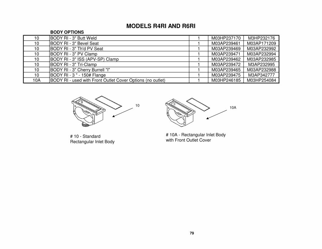
MODELS R4RI AND R6RIBODY OPTIONS
10 BODY RI - 3" Butt Weld 1 M03HP237170 M3HP232176
10 BODY RI - 3" Bevel Seat 1 M03AP239461 M03AP171209
10 BODY RI - 3" Th'd PV Seat 1 M03AP239469 M03AP232992
10 BODY RI - 3" PV Clamp 1 M03AP239471 M03AP232994
10 BODY RI - 3" ISS (APV-SP) Clamp 1 M03AP239462 M03AP232985
10 BODY RI - 3" Tri-Clamp 1 M03AP239472 M3AP232995
10 BODY RI - 3" Cherry Burrell "I" 1 M03AP239465 M03AP232988
10 BODY RI - 3 " - 150# Flange 1 M03AP239475 M3AP34277710A BODY RI - used with Front Outlet Cover Options (no outlet) 1 M03HP246185 M03HP254084
# 10 - Standard
Rectangular Inlet Body
# 10A - Rectangular Inlet Body
with Front Outlet Cover
1010A
79

MODELS R4RI AND R6RIGEAR CASE OPTIONS
ITEM DESCRIPTION QTY. R4 R6
19 GEAR CASE & COVER - SIDE FEED (STANDARD) 1 M03AP144593 M03AP14459319 GEAR CASE & COVER - TOP FEED 1 M03AP254038 M03AP254038
GEAR CASE & PLUG ASSEMBLY (Includes items #16, 17, 18, 19, 21, 23, 26)
19B GEAR CASE & PLUG ASSEMBLY - SIDE FEED (STD) 1 M03WP144593 M03WP14459319B GEAR CASE & PLUG ASSEMBLY - TOP FEED 1 M03WP162892 M03WP162892
GEAR CASE ASSEMBLY - INCL SHAFTS - (Includes Items 12-31, excluding #15) (see note below)
19A GEAR CASE ASY - SIDE FEED - TOP SHAFT - M03AP454807 M03AP454536
19A GEAR CASE ASY - SIDE FEED - BOTTOM SHAFT - M03AP454808 M03AP454537
19A GEAR CASE ASY - TOP FEED - RH SHAFT-PED MT (*) - M03AP454811 M03AP454540
19A GEAR CASE ASY - TOP FEED - LH SHAFT-PED MT (*) - M03AP454812 M03AP454541
19A GEAR CASE ASY - TOP FEED - RH SHAFT-FLOOR MT - M03AP454815 M03AP454544
19A GEAR CASE ASY - TOP FEED - LH SHAFT-FLOOR MT - M03AP454816 M03AP454545
19A GEAR CASE ASY - TOP FEED - RH SHAFT-CEILING MT - M03AP454817 M03AP45454619A GEAR CASE ASY - TOP FEED - LH SHAFT-CEILING MT - M03AP454818 M03AP454547
(*) These items include pedestal (#50)GEAR CASE ASSEMBLY - WATER FLUSH SEAL (Includes Items 12-31, excluding #15) (see note below)
19A GEAR CASE ASY - SIDE FEED - TOP SHAFT - WFS - M03AP454809 M03AP454538
19A GEAR CASE ASY - SIDE FEED - BOTTOM SHAFT - WFS - M03AP454810 M03AP454539
19A GEAR CASE ASY -TOP FEED-RH SHAFT-PED MT-WFS (*) - M03AP454813 M03AP45454219A GEAR CASE ASY - TOP FEED-LH SHAFT-PED MT-WFS (*) - M03AP454814 M03AP454543
(*) These items include pedestal (#50)
50 SUPPORT POST - PEDESTAL MOUNT - M03HP162866 M03HP162866
PART NUMBERS
50
Top Feed - RH or LH shaft
is determined when looking
at pump from the front cover end.
Pedestal (#50) is only included
with gear case assemblies
marked with an asterisk (*).
19A19
Top or Bottom Shaft
50
80

MODELS R4HD, R6HD
81
08-R Manual-2004-R4-R6HD.xls, R4HD-R6HD

MODELS R4HD, R6HD
R4HD R6HD
1 CAP - Bearing End, Heavy-Duty 2 M03HP225266 M03HP225266
2 SCREW 2 M521P229095 M521P229095
3 WASHER 2 M523V008819 M523V008819
4 PLATE & PIN (RETAINING WASHER) 2 M03AP225267 M03AP225267
5 BEARING ASSEMBLY - Outboard Complete (INCL 5A & 5B below) 2 M03AP232733 M03AP232733
5A Bearing - inner race - M03HP225661 M03HP225661
5B Bearing - outer race - M621S8184B M621S8184B6 RING - Retainer 2 M03HP225033 M03HP225033
NUT - Hex (Stainless Steel) 8 M523V006529 M523V006529NUT - Wing 8 M727P397882 M727P397882
8 COVER - HEAVY DUTY - (includes # 5 and #6 above) 19 GASKET - Cover (Paper) Heavy-Duty (sold in boxes of 100) 1 M541P171854 M541P171854
CARTRIDGE - Front Seal & Spacer HD Seal (standard) 2 M03HP280219 M03HP280219
CARTRIDGE - Front Seal & Spacer WFS 2 M03HP257717 M03HP257717CARTRIDGE - Front Seal & Spacer DEARATOR/DEGASSER 2 M03HP232854 M03HP232854
11 O-RING (Sold in pks of 10pcs) 2 M543S131402 M543S131402
12 O-RING - Pump Seal (Sold in pks of 10pcs) 4 M543S131405 M543S131405
13 BEARING - Seal (Stainless Steel) 4 M03HP137734 M03HP137734
14 SEAL - Shaft (Sold in pks of 10pcs) 4
15 ROTORS - 5 Lobe 2
16 PIN - Locating 2 M525S1670G M525S1670G
17 STUD - Short Round 4 M03HP167185 M03HP16718518 BODY - Heavy Duty Pump 1
STUD - Long Round (3 round studs and 1 hex stud per pump) 3 M03HP133604 M03HP133626STUD - Long Hex (3 round studs and 1 hex stud per pump) 1 M03HP228959 M03HP233789
24 RING - Seal (Sold in pks of 5pcs) 2 M03HP137738 M03HP13773825 SEAL - Front Oil 2 M543SK609 M543SK609
PLUG - Locating 2 M03HP133603 M03HP133603PLUG - Locating, WFS 2 M03HP218225 M03HP218225
27 GEAR CASE ASSEMBLY --see Gearcase section 1
28 OIL PLUG 2 M569P454190 M569P454190
29 SIGHT GLASS 1 M569P454191 M569P45419132 BREATHER/OIL FILLER 1 M569P454192 M569P454192
See Rotors
see gearcase section
see Body section
See Front Covers
See Shaft Seals
PART NO.
QTY.ITEM DESCRIPTION
23
26
7
10
82
08-R Manual-2004-R4-R6HD.xls, R4HD-R6HD

MODELS R4HD, R6HD
R4HD R6HD
33 GASKET - Gear Case 1 M549P137756 M549P137756
34 O-RING - Bearing Seal - Heavy Duty (Sold in pks of 5pcs) 2 M543S131422 M543S131422
35 NUT - Bearing Adjustment - 2-1/4 SHAFT 1 M03HP255805 M03HP255805
36 SEAL - Real Oil 1 M543SK609 M543SK609
37 SCREW - Set 4 M522V006970 M522V006970
38 NUT - Bearing Adjustment & Seal Retainer - 2-1/4 SHAFT 1 M03HP255804 M03HP255804
39 SCREW 6 M522V006804 M522V006804
40 RING - Retaining 2 M689P138716 M689P138716
41 BEARING - Front - Tapered Roller 2 M621S4158B M621S4158B
42 SHAFT & GEAR ASSEMBLY - Short -2-1/4 SHAFT 1 M03AP262758 M03AP255811
42 SHAFT & GEAR ASSEMBLY - Short - 1-3/8" SHAFT * 1 M03AP228223 M03AP232749 (*)
43 SHAFT & GEAR ASSEMBLY - Long - 2-1/4 SHAFT 1 M03AP262756 M03AP255810 (*)
43 SHAFT & GEAR ASSEMBLY - Long - 1-3/8" SHAFT * M03AP228224 M03AP23275044 BEARING - Rear - Tapered Roller 2 M621S4158B M621S4158B
(*) These part numbers apply for gearcases with 1-3/8" imput shaft on some older models
Please provide serial number when ordering parts for these models
COVER OPTIONS
R4HD R6HD
8 COVER - HEAVY DUTY - STANDARD (includes # 5 and #6 above) 1 M03AP185437 M03AP185437
8 COVER-HD-WATER FLUSH SEAL (includes # 5 and #6 above) 1 M03AP257405 M03AP2574058 COVER - HD - Deaerator/degasser (includes # 5 and #6 above) 1 M03AP250555 M03AP250555
ITEM DESCRIPTION QTY.
PART NO.
PART NO.
DESCRIPTION QTY.ITEM
HEAVY DUTY COVER WITH
DEAERATOR/DEGASSER
82
83
STD HEAVY DUTY COVER
08-R Manual-2004-R4-R6HD.xls, R4HD-R6HD

MODELS R4HD, R6HD
BODY OPTIONS
R4HD R6HD
18 BODY HD - 2" Butt Weld 1 M03AP452722 N/A
18 BODY HD - 2" Bevel Seat 1 M03AP229050 N/A
18 BODY HD - 2" Th'd PV Seat 1 M03AP229058 N/A
18 BODY HD - 2" APC-PV Clamp 1 M03AP229060 N/A
18 BODY HD - 2" ISS (APV-SP) Clamp 1 M03AP229051 N/A
18 BODY HD - 2" Tri-Clamp 1 M03AP229061 N/A
18 BODY HD - 2" Cherry Burrell "I" 1 M03AP229054 N/A18 BODY HD - 2" Flange 1 M03AP229063 N/A
18 BODY HD - 2-1/2" Bevel Seat 1 N/A M03AP180920
18 BODY HD - 3" Butt Weld 1 M03AP228206 M03AP221433
18 BODY HD - 3" Bevel Seat 1 M03AP228193 M03AP180921
18 BODY HD - 3" Th'd PV Seat 1 M03AP228201 M03AP221429
18 BODY HD - 3" APC-PV Clamp 1 M03AP228203 M03AP221431
18 BODY HD - 3" ISS (APV-SP) Clamp 1 M03AP228194 M03AP221422
18 BODY HD - 3" Tri-Clamp 1 M03AP228204 M03AP221432
18 BODY HD - 3" Cherry Burrell "I" 1 M03AP228197 M03AP22142518 BODY HD - 3 " - Flange 1 M03AP229077 M03AP221434
QTY.
PART NO.
ITEM DESCRIPTION
84
08-R Manual-2004-R4-R6HD.xls, R4HD-R6HD

MODELS R4HD, R6HD
GEARCASE OPTIONS
R4HD R6HD
27 GEAR CASE & COVER ASSEMBLY 1 M03AP262754 M03AP26275427 GEAR CASE & COVER ASSY -TF-Ped/floor mount 1 M03AP280214 M03AP280214
GEAR CASE & PLUG ASSEMBLY - (Includes Items 27-29, 32, 33, 35, 38, 39)
27B GEAR CASE & PLUG ASSEMBLY (#13, 18, 21)TOP FEED 1 M03WP262754 M03WP26275427B GEAR CASE & PLUG ASSY - TF-PED/FLR MT 1 M03WP280214 M03WP280214
GEAR CASE ASSEMBLY - INCL SHAFTS - (Includes Items 24-29, 32-44)
27A GEAR CASE ASY - TOP SHAFT 1 M03AP454789 M03AP454518
27A GEAR CASE ASY - BOTTOM SHAFT 1 M03AP454790 M03AP454519
27A GEAR CASE ASY -TOP FEED - RH SHAFT-PED MT (*) 1 M03AP454793 M03AP454522
27A GEAR CASE ASY - TOP FEED - LH SHAFT-PED MT (*) 1 M03AP454794 M03AP454523
27A GEAR CASE ASY -TOP FEED - RH SHAFT-FLR MT 1 M03AP454797 M03AP45452627A GEAR CASE ASY - TOP FEED - LH SHAFT-FLR MT 1 M03AP454798 M03AP454527
(*) These items include support post (#50) and support bracket (#51)GEARCASE ASSEMBLY OPTIONS - WATER FLUSH SEAL (Includes Items 24-29, 32-44)
27A GEAR CASE ASY - TOP SHAFT 1 M03AP454791 M03AP454520
27A GEAR CASE ASY - BOTTOM SHAFT 1 M03AP454792 M03AP454521
27A GEAR CASE ASY -TOP FEED - RH SHAFT-PED MT (*) 1 M03AP454795 M03AP45452427A GEAR CASE ASY - TOP FEED - LH SHAFT-PED MT (*) 1 M03AP454796 M03AP454525
(*) These items include support post (#50) and support bracket (#51)
50 SUPPORT POST - PEDESTAL MOUNT 1 M03HP162866 M03HP16286651 SUPPORT BRACKET - PEDESTAL MOUNT 1 M03HP177674 M03HP177674
NOTE: All gearcases listed on this page have 2-1/4" drive shaft.
Some older models have 1-3/8" drive shaft. Call for part number (serial number required.).
ITEM DESCRIPTION QTY.
PART NO.
27A27
50
Top or Bottom Shaft
Top Feed - RH or LH shaft is
determined when looking at pump
from the front cover end. Post
(50) and bracket (51) are only
included with gear case
assemblies marked with an
asterisk (*).
51
85
08-R Manual-2004-R4-R6HD.xls, R4HD-R6HD

MODELS R4HDRI, R6HDRI
86
09-R Manual-2004-R4HDRI-R6HDRI.xls,R4HDRI-R6HDRI

MODELS R4HDRI, R6HDRI
R4HDRI R6HDRI
1 CAP - Bearing End, Heavy Duty 2 M03HP225266 M03HP2252662 BOLT 2 M521P229095 M521P2290953 WASHER 2 M523V008819 M523V0088194 PLATE & PIN - Bearing - Retainer, HD 2 M03AP225267 M03AP2252675 BEARING Assembly - Outboard Complete 2 M03AP232733 M03AP232733
5A Bearing - inner race - M03HP225661 M03HP2256615B Bearing - outer race - M621S8184B M621S8184B
6 RING - Retainer 2 M03HP225033 M03HP2250337 COVER - HEAVY DUTY - see Covers 1 See Covers See Covers
NUT - Hex (Stainless Steel) 8 M523V006529 M523V006529NUT - Wing 8 M727P397882 M727P397882
9 GASKET - Cover (Paper) Heavy-Duty (sold in boxes of 100) 1 M541P171854 M541P171854
CARTRIDGE - Front Seal & Spacer HD Seal (standard) 2 M03HP280219 M03HP280219CARTRIDGE - Front Seal & Spacer WFS 2 M03HP257717 M03HP257717CARTRIDGE - Front Seal & Spacer DEARATOR/DEGASSER 2 M03HP232854 M03HP232854
11 O-RING - Bearing Seal, Heavy-Duty (Sold in pks of 10pcs) 2 M543S131402 M543S13140212 O-RING - Pump Seal (Sold in pks of 10pcs) 4 M543S131405 M543S13140513 BEARING - Seal, SS, Standard 4 M03HP137734 M03HP13773414 SEAL - Shaft (Sold in pks of 10pcs) 2 See Shaft Seals See Shaft Seals15 ROTORS - 5 Lobe 2 See Rotors See Rotors16 STUD - Short Round 4 M03HP167185 M03HP16718517 SCREW 2 M521V006688 M521V00668818 PIN - Locating 2 M525S1670G M525S1670G19 BODY - see body section 1 See Body Section See Body Section24 STUD - Long Round 4 M03HP133604 M03HP13362625 RING - Seal (Sold in pks of 10pcs) 2 M03HP137738 M03HP13773826 SEAL - Front Oil 2 M543SK609 M543SK609
PLUG - Locating 2 M03HP133603 M03HP133603PLUG - Locating, WFS 2 M03HP218225 M03HP218225
28 GEAR CASE ASSEMBLY --see Gearcase section 1 See Gearcases See Gearcases29 BREATHER/OIL FILLER 1 M569P454192 M569P45419232 GASKET - Gear Case 1 M549P137756 M549P13775633 SCREW 6 M522V006804 M522V006804
O-RING - Bearing Seal 2-1/4" SHAFT (Sold in pks of 5pcs) 2 M543S131422 M543S131422O-RING - Bearing Seal 1-3/8" SHAFT (*) (Sold in pks of 10pcs) 2 M543S131413 M543S131413 (*)
NUT - Bearing Adjustment - 2-1/4" SHAFT 1 M03HP255805 M03HP255805NUT - Bearing Adjustment - 1-3/8" SHAFT (*) 1 M03HP133580 M03HP133580 (*)
10
8
27
34
35
QTY.DESCRIPTIONITEM
PART NO.
87
09-R Manual-2004-R4HDRI-R6HDRI.xls,R4HDRI-R6HDRI

MODELS R4HDRI, R6HDRI
R4HDRI R6HDRI
36 SCREW 4 M522V006970 M522V006970
SEAL - Real Oil 2-1/4" SHAFT 1 M543SK609 M543SK609SEAL - Real Oil 1-3/8" SHAFT (*) 1 M543SK608 M543SK608 (*)
NUT - Bearing Adjustment & Seal Retainer - 2-1/4" SHAFT 1 M03HP255804 M03HP255804NUT - Bearing Adjustment & Seal Retainer - 1-3/8" SHAFT (*) 1 M03HP133578 M03HP133578 (*)
39 SIGHT GLASS 1 M569P454191 M569P45419140 OIL PLUG 1 M569P454190 M569P45419041 PEDESTAL 1 M03HP162866 M03HP16286642 RING - Retaining 1 M689P138716 M689P13871643 BEARING - Gear Case - Front (Tapered Roller) 2 M621S4158B M621S4158B
44 SHAFT & GEAR ASSEMBLY - Short -2-1/4" SHAFT 1 M03AP262758 M03AP25581144 SHAFT & GEAR ASSEMBLY - Short - 1-3/8" SHAFT (*) 1 M03AP228223 M03AP232749 (*)
45 SHAFT & GEAR ASSEMBLY - Long - 2-1/4" SHAFT 1 M03AP262756 M03AP25581045 SHAFT & GEAR ASSEMBLY - Long - 1-3/8" SHAFT (*) 1 M03AP228224 M03AP232750 (*)
BEARING - Rear - Tapered Roller - 2-1/4" SHAFT 2 M621S4158B M621S4158BBEARING - Rear - Tapered Roller - 1-3/8" SHAFT (*) 2 M621S4158F M621S4158F (*)
47 GASKET - Rectangular Inlet Flange 1 M03HP334134 M03HP33413651 SUPPORT - HDRI Pedestal Mount-see gear cases 1 M03HP177674 M03HP177674
(*) These part number apply for gearcases with 1-3/8" input shaft on some older models.Please provide serial number when ordering parts for these models
37
38
46
ITEM DESCRIPTION QTY.
PART NO.
87
88
09-R Manual-2004-R4HDRI-R6HDRI.xls,R4HDRI-R6HDRI

MODELS R4HDRI, R6HDRI
HEAVY DUTY COVER OPTIONS
R4HDRI R6HDRI
7 COVER - Heavy-Duty Rectangular Inlet - Incl. #5 and #6 above 1 M03AP185437 M03AP1854377 COVER - HDRI Deaerator/Degasser - Incl. #5 and #6 above 1 M03AP250555 M03AP2505557 COVER - HDRI Water Flush Seal - Incl. #5 and #6 above 1 M03AP257405 M03AP257405
FRONT OUTLET COVER OPTIONS (use with body for HDRI Front Outlet)
7 COVER - HDRI Front Outlet - 3 in. Th'd Bevel Seat 1 M03AP255358 M03AP2553587 COVER - HDRI Front Outlet - 3 in. Th'd PV Seat 1 M03AP454224 M03AP4542247 COVER - HDRI Front Outlet - 3 in. PV Clamp 1 M03AP454225 M03AP4542257 COVER - HDRI Front Outlet - 3 in. ISS (APV-SP) 1 M03AP447401 M03AP4474017 COVER - HDRI Front Outlet - 3 in. Tri-Clamp 1 M03AP401473 M03AP4014737 COVER - HDRI Front Outlet - 3 in. Cherry-Burrell "I" 1 M03AP454226 M03AP4542267 COVER - HDRI Front Outlet - 3 in. Butt Weld 1 M03AP454227 M03AP4542277 COVER - HDRI Front Outlet - 4 in. Th'd Bevel Seat 1 N/A M03AP2718857 COVER - HDRI Front Outlet - 4 in. Th'd PV Seat 1 N/A M03AP4542287 COVER - HDRI Front Outlet - 4 in. PV Clamp 1 N/A M03AP2887487 COVER - HDRI Front Outlet - 4 in. ISS (APV-SP) 1 N/A M03AP4542297 COVER - HDRI Front Outlet - 4 in. Tri-Clamp 1 N/A M03AP4119427 COVER - HDRI Front Outlet - 4 in. Cherry-Burrell "I" 1 N/A M03AP4542307 COVER - HDRI Front Outlet - 4 in. Butt Weld 1 N/A M03AP381392
FRONT OUTLET COVER OPTIONS with DEAERATOR/DEGASSER (use with body for HDRI Front Outlet)
7 COVER - HDRI D/D Front Outlet - 3 in. Th'd Bevel Seat 1 M03AP830461 M03AP8304617 COVER - HDRI D/D Front Outlet - 3 in. Th'd PV Seat 1 M03AP830460 M03AP8304607 COVER - HDRI D/D Front Outlet - 3 in. PV Clamp 1 M03AP830459 M03AP8304597 COVER - HDRI D/D Front Outlet - 3 in. ISS (APV-SP) 1 M03AP830458 M03AP8304587 COVER - HDRI D/D Front Outlet - 3 in. Tri-Clamp 1 M03AP830457 M03AP8304577 COVER - HDRI D/D Front Outlet - 3 in. Cherry-Burrell "I" 1 M03AP830456 M03AP8304567 COVER - HDRI D/D Front Outlet - 3 in. Butt Weld 1 M03AP830455 M03AP8304557 COVER - HDRI D/D Front Outlet - 4 in. Th'd Bevel Seat 1 N/A M03AP8304537 COVER - HDRI D/D Front Outlet - 4 in. Th'd PV Seat 1 N/A M03AP8304527 COVER - HDRI D/D Front Outlet - 4 in. PV Clamp 1 N/A M03AP8304517 COVER - HDRI D/D Front Outlet - 4 in. ISS (APV-SP) 1 N/A M03AP8304507 COVER - HDRI D/D Front Outlet - 4 in. Tri-Clamp 1 N/A M03AP8304497 COVER - HDRI D/D Front Outlet - 4 in. Cherry-Burrell "I" 1 N/A M03AP8304487 COVER - HDRI D/D Front Outlet - 4 in. Butt Weld 1 N/A M03AP830447
DESCRIPTIONITEM
PART NO.
QTY.
STD HEAVY DUTY COVER
HEAVY DUTY COVER WITH
DEAERATOR/DEGASSER
STD HEAVY DUTY COVER
WITH FRONT OUTLET
HEAVY DUTY COVER WITH
DEAERATOR/DEGASSER
AND FRONT OUTLET89
09-R Manual-2004-R4HDRI-R6HDRI.xls,R4HDRI-R6HDRI

MODELS R4HDRI, R6HDRI
BODY OPTIONS
R4HDRI R6HDRI
19 BODY - HDRI - Front Outlet (use with front outlet cover) 1 M03AP254597 M03AP25536647 GASKET - Rectangular Inlet Flange 1 M03HP334134 M03HP334136
19 BODY - HDRI - 3" Bevel Seat 1 M03AP242000 M03AP27184419 BODY - HDRI - 3" Threaded PV Seat 1 M03AP242008 M03AP27183919 BODY - HDRI - 3" APC-PV Clamp 1 M03AP242008 M03AP27184119 BODY - HDRI - 3" ISS (APV - SP) 1 M03AP242001 M03AP27183219 BODY - HDRI - 3" Tri-Clamp 1 M03AP242008 M03AP27184219 BODY - HDRI - 3" Cherry-Burrell "I" 1 M03AP242004 M03AP27183519 BODY - HDRI - 3" Flange 1 M03AP242013 M03AP27184519 BODY - HDRI - 3" Butt Weld 1 M03AP452723 M03AP27184347 GASKET - Rectangular Inlet Flange 1 M03HP334134 M03HP334136
ITEM DESCRIPTION QTY.
PART NO.
BODY-HDRI Use with
FRONT OUTLET COVER BODY-HDRI STD OUTLET
90
09-R Manual-2004-R4HDRI-R6HDRI.xls,R4HDRI-R6HDRI

MODELS R4HDRI, R6HDRI
GEARCASE OPTIONS
R4HDRI R6HDRI
28 GEARCASE & COVER ASSY - "B" MOUNT (STANDARD) 1 M03AP262754 M03AP26275428 GEAR CASE & COVER ASSY -TF-Ped/floor mount 1 M03AP280214 M03AP280214
GEAR CASE & PLUG ASSEMBLY - (Includes Items 28,29,32,33,35,38,39,40)
28B GEAR CASE & PLUG ASSY - "B" MOUNT (STANDARD) 1 M03WP262754 M03WP26275428B GEAR CASE & PLUG ASSY - TF-PED/FLR MT 1 M03WP280214 M03WP28021428B GEAR CASE & PLUG ASSY - TF-CEILING MT 1 M03WP280214 M03WP280214
GEAR CASE ASSEMBLY - INCL SHAFTS - (Includes Items 25-29,32-40, 42-46)
28A GEAR CASE ASY - TOP SHAFT 1 M03AP454789 M03AP45451828A GEAR CASE ASY - BOTTOM SHAFT 1 M03AP454790 M03AP45451928A GEAR CASE ASY -TOP FEED - RH SHAFT-PED MT (+) 1 M03AP454793 M03AP45452228A GEAR CASE ASY - TOP FEED - LH SHAFT-PED MT (+) 1 M03AP454794 M03AP45452328A GEAR CASE ASY -TOP FEED - RH SHAFT-FLR MT 1 M03AP454797 M03AP45452628A GEAR CASE ASY - TOP FEED - LH SHAFT-FLR MT 1 M03AP454798 M03AP454527
(+) These items include pedestal (#50) and support bracket (#51)GEARCASE ASSEMBLY OPTIONS - WATER FLUSH SEAL (Includes Items 25-29,32-40, 42-46)
28A GEAR CASE ASY - TOP SHAFT 1 M03AP454791 M03AP45452028A GEAR CASE ASY - BOTTOM SHAFT 1 M03AP454792 M03AP45452128A GEAR CASE ASY -TOP FEED - RH SHAFT-PED MT (+) 1 M03AP454795 M03AP45452428A GEAR CASE ASY - TOP FEED - LH SHAFT-PED MT (+) 1 M03AP454796 M03AP454525
(+) These items include pedestal (#50) and support bracket (#51)
41 SUPPORT POST - PEDESTAL MOUNT 1 M03HP162866 M03HP16286651 SUPPORT BRACKET - PEDESTAL MOUNT 1 M03HP177674 M03HP177674
*************NOTE: All gearcases listed on this page have 2-1/4" drive shaft.*********************
********* Some older models have 1-3/8" drive shaft. Call for part number (serial number required.). *****************
PART NO.
DESCRIPTIONITEM QTY.
27A27
41
Top or Bottom Shaft
Top Feed - RH or LH shaft is
determined when looking at
pump from the front cover end.
Post (41) and bracket (51) are
only included with gear case
assemblies marked with a plus
sign (+).
51
91
09-R Manual-2004-R4HDRI-R6HDRI.xls,R4HDRI-R6HDRI

MODEL R700HD
92
10-R Manual-2004-R700HD.xls, R700HD

MODEL R700HD
R700HD
1 CAP - Bearing End, Heavy-Duty 2 M03HP225266
2 SCREW 2 M521P229095
3 WASHER 2 M523V0088194 PLATE & PIN (RETAINING WASHER) 2 M03AP225267
5 BEARING ASSEMBLY - Outboard Complete (INCL 5A & 5B below) 2 M03AP232733
5A Bearing - inner race - M03HP2256615B Bearing - outer race - M621S8184B
6 RING - Retainer 2 M03HP2250337 NUT - Hex (Stainless Steel) 8 M523V006529
COVER - HEAVY DUTY - STANDARD (includes # 5 and #6 above) 1 M03AP185437
COVER - HD Water Flush Seal (includes #5 and #6 above) 1 M03AP257405COVER - HD - Deaerator/degasser (includes #5 and #6 above) 1 M03AP250555
9 GASKET - Cover (Paper) Heavy-Duty (sold in boxes of 100) 1 M541P171854
CARTRIDGE - Front Seal & Spacer HD Seal 2 M03HP280219
CARTRIDGE - Front Seal & Spacer WFS 2 M03HP257717CARTRIDGE - Front Seal & Spacer DEAERATOR/DEGASSER 2 M03HP232854
11 O-RING (Sold in pks of 10pcs) 2 M543S131402
12 O-RING - Pump Seal (Sold in pks of 10pcs) 4 M543S131405
13 BEARING - Seal (Stainless Steel) 2 M03HP137734
14 SEAL - Shaft (Sold in pks of 10pcs) 4 See Shaft Seals
15 ROTORS - 5 Lobe 4 See Rotors
16 PIN - Locating 2 M525S1670G
17 STUD - Short Round 4 M03HP167185
18 BODY - Heavy Duty Pump 1 see body section
19 EYE BOLT 2 M03AP23333520 SCREW 2 M521V006695
O-RING - Rear Cartridge (sold in pks of 5pcs) 2 M543S131351O-RING - WFS (Sold in pks of 5pcs) 2 M543S131349
CARTRIDGE - Rear Seal & Spacer HD Seal Kit 2 M03HP171697
CARTRIDGE - Rear Seal & Spacer WFS Kit 2 M03HP257381CARTRIDGE - Rear Seal & Spacer Deaerator/degasser 2 M03HP331708
STUD - Long Round (3 round studs and 1 hex stud per pump) 3 M03HP167060STUD - Long Hex (3 round studs and 1 hex stud per pump) 1 M03HP167061
ITEM DESCRIPTION QTY.
23
8
10
21
22
93
10-R Manual-2004-R700HD.xls, R700HD

MODEL R700HD
R700HD
24 RING - Seal (Sold in packs of 5pcs) 2 M03HP13773825 SEAL - Front Oil 2 M543SK609
PLUG - Locating 2 M03HP167428PLUG - Locating, WFS 2 M03HP257380
27 GEAR CASE ASSEMBLY --see Gearcase section 1 see gearcases
28 OIL PLUG 2 M569P454190
29 SIGHT GLASS 1 M569P454191
30 WASHER 2 M523V007193
31 NUT 2 M523V006529
32 BREATHER/OIL FILLER 1 M569P45419233 GASKET - Gear Case 1 M549P137756
O-RING - Bearing Seal 2-1/4" shaft (Sold in pks of 5pcs) 2 M543S131422O-RING - Bearing Seal 1-3/8" shaft (*) (Sold in pks of 10pcs) 2 M543S131413 (*)
NUT - Bearing Adjustment - 2-1/4 SHAFT 1 M03HP255805NUT - Bearing Adjustment - 1-3/8 SHAFT (*) 1 M03HP133580 (*)
SEAL - Real Oil 2-1/4" shaft 1 M543SK609SEAL - Real Oil 1-3/8" shaft (*) 1 M543SK608 (*)
37 SCREW - Set 4 M522V006970
NUT - Bearing Adjustment & Seal Retainer - 2-1/4 SHAFT 1 M03HP255804NUT - Bearing Adjustment & Seal Retainer - 1-3/8 SHAFT (*) 1 M03HP133578 (*)
39 SCREW 6 M522V006804
40 RING - Retaining 2 M689P13871641 BEARING - Front - Tapered Roller 2 M621S4158B
SHAFT & GEAR ASSEMBLY - Short -2-1/4 SHAFT 1 M03AP257564SHAFT & GEAR ASSEMBLY - Short - 1-3/8 SHAFT (*) 1 M03AP232813 (*)
SHAFT & GEAR ASSEMBLY - Long - 2-1/4 SHAFT 1 M03AP257565SHAFT & GEAR ASSEMBLY - Long - 1-3/8 SHAFT (*) 1 M03AP232814 (*)
BEARING - Rear - Tapered Roller - 2-1/4" SHAFT 2 M621S4158BBEARING - Rear - Tapered Roller - 1-3/8" SHAFT (*) 2 M621S4158F (*)
(*) These part number apply for gearcases with 1-3/8" input shaft on some older models.
Please provide serial number when ordering parts for these models
42
43
35
DESCRIPTION QTY.
26
44
38
ITEM
34
36
93
94
10-R Manual-2004-R700HD.xls, R700HD

MODEL R700HD
COVER OPTIONS
R700HD
8 COVER - HEAVY DUTY - STANDARD 1 M03AP185437
8 COVER - HD - STD - WATER FLUSH SEAL 1 M03AP2574058 COVER - HD - Deaerator/degasser 1 M03AP250555
BODY OPTIONS
18 BODY HD - 4" Butt Weld 1 M03AP267958
18 BODY HD - 4" Bevel Seat 1 M03AP267951
18 BODY HD - 4" Th'd PV Seat 1 M03AP267952
18 BODY HD - 4" APC-PV Clamp 1 M03AP267950
18 BODY HD - 4" ISS (APV-SP) Clamp 1 M03AP267960
18 BODY HD - 4" Tri-Clamp 1 M03AP267953
18 BODY HD - 4" Cherry Burrell "I" 1 M03AP26795918 BODY HD - 4 " - Flange 1 M03AP489771
18 BODY HD - 4" Butt Weld TOP FEED OR WFS 1 M03AP267966
18 BODY HD - 4" Bevel Seat TOP FEED OR WFS 1 M03AP267961
18 BODY HD - 4" Th'd PV Seat TOP FEED OR WFS 1 M03AP267962
18 BODY HD - 4" APC-PV Clamp TOP FEED OR WFS 1 M03AP267963
18 BODY HD - 4" ISS (APV-SP) Clamp TOP FEED OR WFS 1 M03AP267964
18 BODY HD - 4" Tri-Clamp TOP FEED OR WFS 1 M03AP267965
18 BODY HD - 4" Cherry Burrell "I" TOP FEED OR WFS 1 M03AP26796718 BODY HD - 4 " - Flange TOP FEED OR WFS 1 N/A
DESCRIPTION QTY.ITEM
STD HEAVY DUTY COVER
HEAVY DUTY COVER WITH
DEAERATOR/DEGASSER
95
10-R Manual-2004-R700HD.xls, R700HD

MODEL R700HD
GEARCASE OPTIONS
R700HD
2-1/4" dia 1-3/8" dia (*)
27 GEAR CASE & COVER ASSEMBLY 1 M03AP262776 M03AP262776
27 GEAR CASE & COVER ASSY -TF-Ped/floor mount 1 M03AP257829 M03AP25782927 GEAR CASE & COVER ASSEMBLY - TF-CEILING MOUNT 1 M03AP257828 M03AP257828
GEAR CASE & PLUG ASSEMBLY - (Includes Items 27-29, 32, 33, 35, 38, 39) 2-1/4" shaft 1-3/8" shaft (*)
27B GEAR CASE & PLUG ASSEMBLY ( 1 M03WP262776 -
27B GEAR CASE & PLUG ASSY - TF-PED/FLR MT 1 M03WP257829 M03WP257344 (*)
27B GEAR CASE & PLUG ASSY-TF-CEILING MT 1 M03WP257828 M03WP257344 (*)
GEAR CASE ASSEMBLY - INCL SHAFTS - (Includes Items 24-29, 32-44) 2-1/4" shaft 1-3/8" shaft (*)
27A GEAR CASE ASY - TOP SHAFT 1 M03AP458329 M03AP458327 (*)
27A GEAR CASE ASY - BOTTOM SHAFT 1 M03AP458330 M03AP458328 (*)
27A GEAR CASE ASY -TOP FEED - RH SHAFT-PED MT (+) 1 M03AP458337 M03AP458335 (*)
27A GEAR CASE ASY - TOP FEED - LH SHAFT-PED MT (+) 1 M03AP458338 M03AP458336 (*)
27A GEAR CASE ASY -TOP FEED - RH SHAFT-FLR MT 1 M03AP458345 M03AP458343 (*)
27A GEAR CASE ASY - TOP FEED - LH SHAFT-FLR MT 1 M03AP458346 M03AP458344 (*)
27A GEAR CASE ASY -TOP FEED - RH SHAFT-CEILING MT 1 M03AP458347 (*)27A GEAR CASE ASY - TOP FEED - LH SHAFT-CEILING MT 1 M03AP458348 (*)
(+) These items include support post (#50) and support bracket (#51)
2-1/4" shaft 1-3/8" shaft (*)
27A GEAR CASE ASY - TOP SHAFT 1 M03AP458333 M03AP458331 (*)
27A GEAR CASE ASY - BOTTOM SHAFT 1 M03AP458334 M03AP458332 (*)
27A GEAR CASE ASY -TOP FEED - RH SHAFT-PED MT (+) 1 M03AP458341 M03AP458339 (*)27A GEAR CASE ASY - TOP FEED - LH SHAFT-PED MT (+) 1 M03AP358342 M03AP458340 (*)
27A (+) These items include support post (#50) and support bracket (#51)
50 SUPPORT POST - PEDESTAL MOUNT 1 M03AP389146 M03AP38914651 SUPPORT BRACKET - PEDESTAL MOUNT 1 M03HP233364 M03HP233364
GEARCASE ASSEMBLY OPTIONS - WATER FLUSH SEAL
(Includes Items 24-29, 32-44)
ITEM DESCRIPTION QTY.
27A27 50
Top or Bottom Shaft
Top Feed - RH or LH shaft is
determined when looking at pump
from the front cover end. Post (50)
and bracket (51) are only included
with gear case assemblies marked
with an asterisk (*).
51
96
10-R Manual-2004-R700HD.xls, R700HD
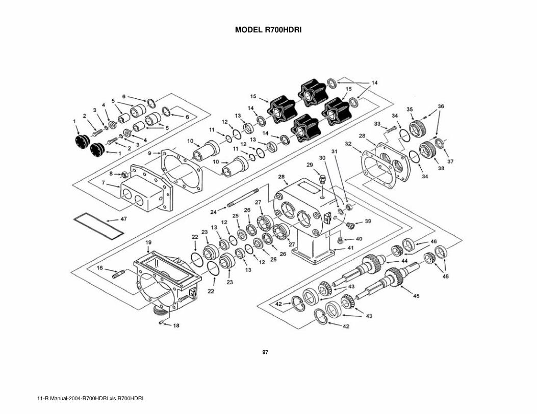
MODEL R700HDRI
97
11-R Manual-2004-R700HDRI.xls,R700HDRI

MODEL R700HDRI
PART NO.
R700HDRI
1 CAP - Bearing End, Heavy Duty 2 M03HP225266
2 BOLT 2 M521P229095
3 WASHER 2 M523V008819
4 PLATE & PIN - Bearing - Retainer, HD 2 M03AP225267
5 BEARING Assembly - Outboard Complete 2 M03AP232733
5A Bearing - inner race - M03HP225661
5B Bearing - outer race - M621S8184B
6 RING - Retainer 2 M03HP225033
7 COVER - see cover section for available options 1 See Covers
8 NUT - Hex (Stainless Steel) 8 M523V006529
9 GASKET - Cover (Paper) Heavy-Duty (sold in pks of 100) 1 M541P171854
CARTRIDGE - Front Seal & Spacer HD Seal (standard) 2 M03HP280219
CARTRIDGE - Front Seal & Spacer WFS 2 M03HP257717
CARTRIDGE - Front Seal & Spacer DEARATOR/DEGASSER 2 M03HP232854
11 O-RING - Bearing Seal, Heavy-Duty (Sold in pks of 10pcs) 2 M543S131402
12 O-RING - Pump Seal (Sold in pks of 10pcs) 4 M543S131405
13 BEARING - Seal, SS, Standard 4 M03HP137734
14 SEAL - Shaft (Sold in pks of 10pcs) 2 See Shaft Seals
15 ROTORS - 5 Lobe 4 See Rotors
16 STUD - Short Round 4 M03HP167185
17 SCREW 2 M521V006695
18 PIN - Locating 2 M525S1670G
19 BODY - see body section 1 See Body Section
20 EYE BOLT ("B" MOUNT ONLY) 2 M03AP233335
21 SCREW ("B" MOUNT ONLY) 2 M521V006695
22 O-RING - Rear Cartridge (Sold in pks of 5pcs) 2 M543S131351
23 CARTRIDGE - Rear Seal & Spacer HD Seal Kit 2 M03HP171697
23 CARTRIDGE - Rear Seal & Spacer Deaerator/Degasser Seal Kit 2 M03HP331708
24 STUD - Long Round 4 M03HP167060
25 RING - Seal (Sold in pks of 5pcs) 2 M03HP137738
26 SEAL - Front Oil 2 M543SK609
PLUG - Locating 2 M03HP167428
PLUG - Locating, WFS 2 M03HP257380
28 GEAR CASE ASSEMBLY --see Gearcase section 1 See Gearcases
29 BREATHER/OIL FILLER 1 M569P454192
ITEM QTY.DESCRIPTION
10
27
"B" Mount Configuration
98
11-R Manual-2004-R700HDRI.xls,R700HDRI

MODEL R700HDRI
PART NO.
R700HDRI
30 WASHER 1 M523V007193
31 NUT 1 M523V006529
32 GASKET - Gear Case 1 M549P137756
33 SCREW 6 M522V006804
O-RING - Bearing Seal 2-1/4" shaft (Sold in pks of 5pcs) 2 M543S131422
O-RING - Bearing Seal 1-3/8" shaft (*) (Sold in pks of 10) 2 M543S131413 (*)
NUT - Bearing Adjustment - 2-1/4 SHAFT 1 M03HP255805
NUT - Bearing Adjustment - 1-3/8 SHAFT (*) 1 M03HP133580 (*)
36 SCREW 4 M522V006970
SEAL - Real Oil 2-1/4" shaft 1 M543SK609
SEAL - Real Oil 1-3/8" shaft 1 M543SK608 (*)
NUT - Bearing Adjustment & Seal Retainer - 2-1/4 SHAFT 1 M03HP255804
NUT - Bearing Adjustment & Seal Retainer - 1-3/8 SHAFT (*) 1 M03HP133578 (*)
39 SIGHT GLASS 1 M569P454191
40 OIL PLUG 1 M569P454190
41 PEDESTAL 1 M03HP389146
42 RING - Retaining 1 M689P138716
43 BEARING - Gear Case - Front (Tapered Roller) 2 M621S4158B
44 SHAFT & GEAR ASSEMBLY - Short -2-1/4 SHAFT 1 M03AP257564
44 SHAFT & GEAR ASSEMBLY - Short - 1-3/8 SHAFT (*) 1 M03AP232813 (*)
45 SHAFT & GEAR ASSEMBLY - Long - 2-1/4 SHAFT 1 M03AP257565
45 SHAFT & GEAR ASSEMBLY - Long - 1-3/8 SHAFT (*) 1 M03AP232814 (*)
BEARING - Rear - Tapered Roller 2 M621S4158B
BEARING - Rear - Tapered Roller 2 M621S4158F (*)
47 GASKET - Rectangular Inlet Flange 1 M03HP334137
51 SUPPORT - HDRI Pedestal Mount-see gear cases 1 M03HP233364
(*) These part number apply for gearcases with 1-3/8" input shaft on some older models.
Please provide serial number when ordering parts for these models
ITEM DESCRIPTION
34
35
QTY.
37
38
46
99
11-R Manual-2004-R700HDRI.xls,R700HDRI

MODEL R700HDRI
HEAVY DUTY COVER OPTIONS
PART NO.
R700HDRI
7 COVER - Heavy-Duty Rectangular Inlet 1 M03AP185437
7 COVER - HDRI Deaerator/Degasser 1 M03AP250555
7 COVER - HDRI Water Flush Seal 1 M03AP257405
FRONT OUTLET COVER OPTIONS (use with body for HDRI Front Outlet)
7 COVER - HDRI Front Outlet - 3 in. Th'd Bevel Seat 1 M03AP255358
7 COVER - HDRI Front Outlet - 3 in. Th'd PV Seat 1 M03AP454224
7 COVER - HDRI Front Outlet - 3 in. PV Clamp 1 M03AP454225
7 COVER - HDRI Front Outlet - 3 in. ISS (APV-SP) 1 M03AP447401
7 COVER - HDRI Front Outlet - 3 in. Tri-Clamp 1 M03AP401473
7 COVER - HDRI Front Outlet - 3 in. Cherry-Burrell "I" 1 M03AP454226
7 COVER - HDRI Front Outlet - 3 in. Butt Weld 1 M03AP454227
7 COVER - HDRI Front Outlet - 4 in. Th'd Bevel Seat 1 M03AP271885
7 COVER - HDRI Front Outlet - 4 in. Th'd PV Seat 1 M03AP454228
7 COVER - HDRI Front Outlet - 4 in. PV Clamp 1 M03AP288748
7 COVER - HDRI Front Outlet - 4 in. ISS (APV-SP) 1 M03AP454229
7 COVER - HDRI Front Outlet - 4 in. Tri-Clamp 1 M03AP411942
7 COVER - HDRI Front Outlet - 4 in. Cherry-Burrell "I" 1 M03AP454230
7 COVER - HDRI Front Outlet - 4 in. Butt Weld 1 M03AP381392
FRONT OUTLET COVER OPTIONS with DEAERATOR/DEGASSER (use with body for HDRI Front Outlet)
7 COVER - HDRI D/D Front Outlet - 3 in. Th'd Bevel Seat 1 M03AP830461
7 COVER - HDRI D/D Front Outlet - 3 in. Th'd PV Seat 1 M03AP830460
7 COVER - HDRI D/D Front Outlet - 3 in. PV Clamp 1 M03AP830459
7 COVER - HDRI D/D Front Outlet - 3 in. ISS (APV-SP) 1 M03AP830458
7 COVER - HDRI D/D Front Outlet - 3 in. Tri-Clamp 1 M03AP830457
7 COVER - HDRI D/D Front Outlet - 3 in. Cherry-Burrell "I" 1 M03AP830457
7 COVER - HDRI D/D Front Outlet - 3 in. Butt Weld 1 M03AP830455
7 COVER - HDRI D/D Front Outlet - 4 in. Th'd Bevel Seat 1 M03AP830453
7 COVER - HDRI D/D Front Outlet - 4 in. Th'd PV Seat 1 M03AP830452
7 COVER - HDRI D/D Front Outlet - 4 in. PV Clamp 1 M03AP830451
7 COVER - HDRI D/D Front Outlet - 4 in. ISS (APV-SP) 1 M03AP830450
7 COVER - HDRI D/D Front Outlet - 4 in. Tri-Clamp 1 M03AP830449
7 COVER - HDRI D/D Front Outlet - 4 in. Cherry-Burrell "I" 1 M03AP830448
7 COVER - HDRI D/D Front Outlet - 4 in. Butt Weld 1 M03AP830447
DESCRIPTION QTY.ITEM
STD HEAVY DUTY COVER
HEAVY DUTY COVER WITH
DEAERATOR/DEGASSER
STD HEAVY DUTY COVER
WITH FRONT OUTLET
HEAVY DUTY COVER WITH
DEAERATOR/DEGASSER
AND FRONT OUTLET
100
11-R Manual-2004-R700HDRI.xls,R700HDRI

MODEL R700HDRI
BODY OPTIONS
PART NO.
R700HDRI
19 BODY - HDRI - Front Outlet (use with front outlet cover) 1 M03AP454869
47 GASKET - Rectangular Inlet Flange 1 M03HP334137
19 BODY - HDRI - 4" Bevel Seat 1 M03AP389130
19 BODY - HDRI - 4" Threaded PV Seat 1 M03AP389131
19 BODY - HDRI - 4" APC-PV Clamp 1 M03AP389132
19 BODY - HDRI - 4" ISS (APV - SP) 1 M03AP389134
19 BODY - HDRI - 4" Tri-Clamp 1 M03AP389133
19 BODY - HDRI - 4" Cherry-Burrell "I" 1 M03AP389136
19 BODY - HDRI - 4" Flange 1 N/A
19 BODY - HDRI - 4" Butt Weld 1 M03AP389135
47 GASKET - Rectangular Inlet Flange 1 M03HP334137
QTY.ITEM DESCRIPTION
BODY-HDRI Use with
FRONT OUTLET COVERBODY-HDRI STD OUTLET
101
11-R Manual-2004-R700HDRI.xls,R700HDRI

MODEL R700HDRI
GEARCASE OPTIONS FOR R700HDRI
2-1/4" shaft 1-3/8" shaft (*)
28 GEAR CASE & COVER ASSY--B MOUNT (STANDARD) 1 M03AP262776 M03AP177376
28 GEAR CASE & COVER ASSY -TF-Ped/floor mount 1 M03AP257829 M03AP257344
28 GEAR CASE & COVER ASSY - TF-CEILING MT 1 M03AP257828 N/A
GEAR CASE & PLUG ASSEMBLY - (Includes Items 28,29,32,33,35,38,39,40) 2-1/4" shaft 1-3/8" shaft (*)
28B GEAR CASE & PLUG ASSY- B MOUNT (STANDARD) 1 M03WP262776 M03WP177376
28B GEAR CASE & PLUG ASSY - TF-PED/FLR MT 1 M03WP257829 M03WP257344 (*)
28B GEAR CASE & PLUG ASSY - TF-CEILING MT 1 M03WP257828 N/A (*)
GEAR CASE ASSEMBLY - INCL SHAFTS - (Includes Items 25-29,32-40, 42-46) 2-1/4" shaft 1-3/8" shaft (*)
28A HD GEAR CASE ASY- TOP SHAFT ( SIDE INLET) 1 M03AP458329 M03AP458327 (*)
28A HD GEAR CASEY ASSY BOTTOM SHAFT (SIDE INLET) 1 M03AP458330 M03AP458328 (*)
28A HD GEAR CASE ASY -TOP FEED - RH SHAFT-PED MT (+) 1 M03AP458337 M03AP458335 (*)
28A HD GEAR CASE ASY - TOP FEED - LH SHAFT-PED MT (+) 1 M03AP458338 M03AP458336 (*)
28A HD GEAR CASE ASY -TOP FEED - RH SHAFT-FLR MT 1 M03AP458345 M03AP458343 (*)
28A HD GEAR CASE ASY - TOP FEED - LH SHAFT-FLR MT 1 M03AP458346 M03AP458344 (*)
(+) These items include pedestal (#50) and support bracket (#51)
2-1/4" shaft 1-3/8" shaft (*)
28A HD GEAR CASE ASY- TOP SHAFT ( SIDE INLET) 1 M03AP458333 M03AP458331 (*)
28A HD GEAR CASE ASY-BOTTOM SHAFT (SIDE INLET) 1 M03AP458334 M03AP458332 (*)
28A HD GEAR CASE ASY -TOP FEED - RH SHAFT-PED MT (+) 1 M03AP458341 M03AP458339 (*)
28A HD GEAR CASE ASY - TOP FEED - LH SHAFT-PED MT (+) 1 M03AP358342 M03AP458340 (*)
(+) These items include pedestal (#50) and support bracket (#51)
41 SUPPORT POST - PEDESTAL MOUNT 1 M03AP389146 M03AP389146
51 SUPPORT BRACKET - PEDESTAL MOUNT 1 M03HP233364 M03HP233364
(*) These part number apply for gearcases with 1-3/8" input shaft on some older models.
Please provide serial number when ordering parts for these models
QTY.
PART NO.
GEARCASE ASSEMBLY OPTIONS - WATER FLUSH SEAL
(Includes Items 25-29,32-40, 42-46)
ITEM DESCRIPTION
28A
28
41
Top or Bottom Shaft
Top Feed - RH or LH shaft is
determined when looking at
pump from the front cover end.
Post (41) and bracket (51) are
only included with gear case
assemblies marked with a plus
sign (+).
51
102
11-R Manual-2004-R700HDRI.xls,R700HDRI

O-RING STYLE BODIES AND COVERS
ITEM DESCRIPTION QTY. R1 R2 R3 R3HD
COVER 1 M03HP481337 M03HP481337 M03HP484049 M03HP484309
COVER - Vented cover (optional) - see options 1 N/A
COVER - Front - (Option: Deaerator/Degasser) 1 N/A N/A M03AP262079 N/A
3 GASKET - Cover O-Ring 1 M543S1313BS M543S1313BS M543S131437 M543S131437
BODY OPTIONS
ITEM DESCRIPTION QTY. R1 R2 R3 R3HD
8 BODY - 1.5" Butt Weld 1 M03AP484613 M03AP484100 M03HP484132 M03AP484202
8 BODY - 1.5" Bevel Seat 1 M03AP484608 M03AP484095 M03AP484127 M3AP484197
8 BODY - 1.5" Th'd PV Seat 1 M03AP484609 M03AP484096 M03AP484128 M3AP484198
8 BODY - 1.5" PV Clamp 1 M03HP484610 M03AP484097 M03AP484129 M03AP484199
8 BODY - 1.5" ISS 1 M03AP484611 M03AP484098 M03AP484130 M03AP484200
8 BODY - 1.5" Tri-Clamp 1 M03AP484612 M03AP484099 M03AP484131 M03AP484201
8 BODY - 1.5" Cherry Burrell "I" 1 M03AP484614 M03AP484101 M03AP484133 M03AP484202
8 BODY - 1.5" Flange 1 N/A N/A M03AP484134 M03AP484204
8 BODY- 2in. - Butt Weld 1 N/A N/A M03HP484140 M03AP484210
8 BODY - 2" Bevel Seat 1 N/A N/A M03AP484135 M03AP484205
8 BODY - 2" Th'd PV Seat 1 N/A N/A M03AP484136 M03AP484206
8 BODY - 2" PV Clamp 1 N/A N/A M03AP484137 M03AP484207
8 BODY - 2" ISS (APV-SP) Clamp 1 N/A N/A M03AP484138 M03AP484208
8 BODY - 2" Tri-Clamp 1 N/A N/A M03AP484139 M03AP484209
8 BODY - 2" Cherry Burrell "I" 1 N/A N/A M03AP484141 M03AP484211
8 BODY - 2in. - Flange 1 N/A N/A M03AP484142 M03AP484212
2
PART NO.
see VENTED COVER section
PART NO.
103
9x-R Manual-2004-O-ring Body-Cover.xls

O-RING STYLE BODIES AND COVERS
R2RI R3RI R3HDRI
2 COVER - STANDARD FLAT COVER 1 M03HP481337 M03HP484049 M03AP484367
4 ORING - Cover 1 M543S1313BS M543S131320 M543S131437
FRONT COVER OPTIONS
R2RI R3RI R3HDRI
2 COVER - Deaerator/Degasser 1.5" in. 1 N/A N/A N/A
2 COVER - Front Outlet - 2 in. Th'd Bevel Seat 1 N/A M03AP484158 M03AP484224
2 COVER - Front Outlet - 2 in. Th'd PV Seat 1 N/A M03AP484159 M03AP484225
2 COVER - Front Outlet - 2 in. PV Clamp 1 N/A M03AP484160 M03AP484226
2 COVER - Front Outlet - 2 in. ISS (APV-SP) 1 N/A M03AP484161 M03AP484227
2 COVER - Front Outlet - 2 in. Tri-Clamp 1 N/A M03AP484162 M03AP484228
2 COVER - Front Outlet - 2 in. Cherry-Burrell "I" 1 N/A M03AP484164 M03AP484300
2 COVER - Front Outlet - 2 in. Butt Weld 1 N/A M03AP484163 M03AP484229
2 COVER - D/D Front Outlet - 2 in. Th'd Bevel Seat 1 N/A M03AP484167 N/A
2 COVER - D/D Front Outlet - 2 in. Th'd PV Seat 1 N/A M03AP484168 N/A
2 COVER - D/D Front Outlet - 2 in. PV Clamp 1 N/A M03AP484169 N/A
2 COVER - D/D Front Outlet - 2 in. ISS (APV-SP) 1 N/A M03AP484170 N/A
2 COVER - D/D Front Outlet - 2 in. Tri-Clamp 1 N/A M03AP484171 N/A
2 COVER - D/D Front Outlet - 2 in. Cherry-Burrell "I" 1 N/A M03AP484173 N/A2 COVER - D/D Front Outlet - 2 in. Butt Weld 1 N/A M03AP484172 N/A
QTY.
PART NO.
ITEM DESCRIPTION QTY.
PART NO.
ITEM DESCRIPTION
104
9x-R Manual-2004-O-ring Body-Cover.xls

O-RING STYLE BODIES AND COVERS
BODY OPTIONS
R2RI R3RI R3HDRI
9 BODY - Rect Inlet - 1.5" Butt Weld 1 M03HP484113 N/A N/A
9 BODY - Rect Inlet - 1.5" Bevel Seat 1 M03AP484108 N/A N/A
9 BODY - Rect Inlet - 1.5" Th'd PV Seat 1 M03AP484109 N/A N/A
9 BODY - Rect Inlet - 1.5" APC-PV Clamp Seat 1 M03AP484110 N/A N/A
9 BODY - Rect Inlet - 1.5" ISS 1 M03AP484111 N/A N/A
9 BODY - Rect Inlet - 1.5" Tri-Clamp 1 M03AP484112 N/A N/A
9 BODY - Rect Inlet - 1.5" Cherry Burrell "I" 1 M03AP484114 N/A N/A
9 BODY - Rect Inlet - 1.5" 150# Flange 1 N/A N/A N/A
9 BODY - Rect Inlet - 2" Butt Weld 1 N/A M03HP484154 M03AP484673
9 BODY - Rect Inlet - 2" Bevel Seat 1 N/A M03AP484149 M03AP484985
9 BODY - Rect Inlet - 2" Th'd PV Seat 1 N/A M03AP484150 M03AP484986
9 BODY - Rect Inlet - 2" APC-PV Clamp Seat 1 N/A M03AP484151 M03AP484987
9 BODY - Rect Inlet - 2" ISS 1 N/A M03AP484152 M03AP484988
9 BODY - Rect Inlet - 2" Tri-Clamp 1 N/A M03AP484153 M03AP484989
9 BODY - Rect Inlet - 2" Cherry Burrell "I" 1 N/A M03AP484155 M03AP484990
9 BODY - Rect Inlet - 2" 150# Flange 1 N/A N/A M03AP4846749 BODY - Rect Inlet - use with Front Outlet Cover 1 N/A M03HP484684 M03HP484685
DESCRIPTION QTY.
PART NO.
ITEM
105
9x-R Manual-2004-O-ring Body-Cover.xls

O-RING STYLE BODIES AND COVERS
ITEM DESCRIPTION QTY. R4 R6
NUT - Hex (Stainless Steel) 8 M523V006529 M523V006529
NUT - Wing (optional) 8 M727P397882 M727P397882
COVER - Standard Front Cover 1 M03HP481162 M03HP481162
COVER - Vented cover (optional) - see options 1
COVER - Front - (Option: Deaerator/Degasser) 1
3 ORING - Cover 1 M543S1313EQ M543S1313EQ
BODY OPTIONS
ITEM DESCRIPTION QTY. R4 R6
BODY- 2" Butt Weld 1 M03HP484396 N/A
BODY - 2" Bevel Seat 1 M03AP484391 N/A
BODY - 2" Th'd PV Seat 1 M03AP484392 N/A
BODY - 2" PV (APC) Clamp 1 M03AP484393 N/A
BODY - 2" ISS (APV-SP) Clamp 1 M03AP484394 N/A
BODY - 2" Tri-Clamp 1 M03AP484395 N/A
BODY - 2" Cherry Burrell "I" 1 M03AP484397 N/A
BODY - 2" Flange 1 M03AP484398 N/A
BODY- 2.5" Butt Weld 1 N/A N/A
BODY - 2.5" Bevel Seat 1 N/A N/A
BODY - 2.5" Th'd PV Seat 1 N/A N/A
BODY - 2.5" PV (APC) Clamp 1 N/A N/A
BODY - 2.5" ISS (APV-SP) Clamp 1 N/A N/A
BODY - 2.5" Tri-Clamp 1 N/A N/A
BODY - 2.5" Cherry Burrell "I" 1 N/A N/A
BODY - 2.5" - Flange 1 N/A N/A
BODY- 3" Butt Weld 1 M03AP484735 M03AP484460
BODY - 3" Bevel Seat 1 M03AP484729 M03AP484455
BODY - 3" Th'd PV Seat 1 M03AP484730 M03AP484456
BODY - 3" PV (APC) Clamp 1 M03AP484731 M03AP484457
BODY - 3" ISS (APV-SP) Clamp 1 M03AP484732 M03AP484458
BODY - 3" Tri-Clamp 1 M03AP484733 M03AP484459
BODY - 3" Cherry Burrell "I" 1 M03AP474734 M03AP484461
BODY - 3 " - Flange 1 M03AP484736 M03AP484460
1
2 see vented cover section
see optional cover section
PART NO.
PART NO.
8
8
8
106
9x-R Manual-2004-O-ring Body-Cover.xls

O-RING STYLE BODIES AND COVERS
R4RI R6RI
2 COVER - Rectangular Inlet - STD FLAT COVER 1 M03HP481162 M03HP481162
3 ORING - Cover 1 M543S1313EQ M543S1313EQ
2B COVER - Front Outlet - 3" Butt Weld 1 M03AP484431 M03AP484491
2B COVER - Front Outlet - 3" Th'd Bevel Seat 1 M03AP484426 M03AP484486
2B COVER - Front Outlet - 3" Th'd PV Seat 1 M03AP484427 M03AP484487
2B COVER - Front Outlet - 3" PV (APC) Clamp 1 M03AP484428 M03AP484488
2B COVER - Front Outlet - 3" ISS (APV - SP) 1 M03AP484429 M03AP484489
2B COVER - Front Outlet - 3" Tri-Clamp 1 M03AP484430 M03AP484490
2B COVER - Front Outlet - 3" Cherry-Burrell "I" 1 M03AP484432 M03AP484492
2C COVER - Deaerator/Degasser Front Outlet - 3" Butt Weld 1 M03AP484440 M03AP484802
2C COVER - Deaerator/Degasser Front Outlet - 3" Th'd Bevel Seat 1 M03AP484435 M03AP484795
2C COVER - Deaerator/Degasser Front Outlet - 3" Th'd PV Seat 1 M03AP484436 M03AP484796
2C COVER - Deaerator/Degasser Front Outlet - 3" PV (APC) Clamp 1 M03AP484437 M03AP484798
2C COVER - Deaerator/Degasser Front Outlet - 3" ISS (APV-SP) 1 M03AP484438 M03AP484799
2C COVER - Deaerator/Degasser Front Outlet - 3" Tri-Clamp 1 M03AP484439 M03AP484800
2C COVER - Deaerator/Degasser Front Outlet - 3" Cherry-Burrell "I" 1 M03AP484441 M03AP484801
33 PLUG - DEAERATOR/DEGASSER COVER (see below) 2 M03HP151283 M03HP151283
ITEM DESCRIPTION QTY.
PART NO.
107
9x-R Manual-2004-O-ring Body-Cover.xls

O-RING STYLE BODIES AND COVERS
PART NO. PART NO.
BODY OPTIONS 4RI 6RI
10 BODY RI - 3" Butt Weld 1 M03HP484418 M03HP484478
10 BODY RI - 3" Bevel Seat 1 M03AP484413 M03AP484473
10 BODY RI - 3" Th'd PV Seat 1 M03AP484414 M03AP484474
10 BODY RI - 3" PV Clamp 1 M03AP484415 M03AP484475
10 BODY RI - 3" ISS (APV-SP) Clamp 1 M03AP484416 M03AP484476
10 BODY RI - 3" Tri-Clamp 1 M03AP484417 M03AP484477
10 BODY RI - 3" Cherry Burrell "I" 1 M03AP484419 M03AP484479
10 BODY RI - 3 " - 150# Flange 1 O/A O/A
10A BODY RI - used with Front Outlet Cover Options (no outlet) 1 M03HP484738 M03HP484758
BODY OPTIONS
ITEM DESCRIPTION QTY. R4HD R6HD
BODY- 3" Butt Weld 1 M03AP484727 M03AP484520
BODY - 3" Bevel Seat 1 M03AP484721 M03AP484515
BODY - 3" Th'd PV Seat 1 M03AP484722 M03AP484516
BODY - 3" PV (APC) Clamp 1 M03AP484723 M03AP484517
BODY - 3" ISS (APV-SP) Clamp 1 M03AP484724 M03AP484518
BODY - 3" Tri-Clamp 1 M03AP484725 M03AP484519
BODY - 3" Cherry Burrell "I" 1 M03AP484726 M03AP484521
BODY - 3" Flange 1 M03AP484728 M03AP484522
BODY - 4" Butt-Weld 1 N/A M03AP484528
BODY - 4" Bevel Seat 1 N/A M03AP484523
BODY - 4" Th'd PV Seat 1 N/A M03AP484524
BODY - 4" PV (APC) Clamp 1 N/A M03AP484525
8 BODY - 4" ISS (APV-SP) Clamp 1 N/A M03AP484526
BODY - 4" Tri-Clamp 1 N/A M03AP484527
BODY - 4" Cherry Burrell "I" 1 N/A M03AP484529
BODY - 4" Flange 1 N/A M03AP484530
8
PART NO
108
9x-R Manual-2004-O-ring Body-Cover.xls

O-RING STYLE BODIES AND COVERS
COVER OPTIONS
ITEM DESCRIPTION QTY R4HD R6HD
2 COVER - Standard 1 M03HP484368 M03HP384368
2 COVER - Vented cover (optional) - see options 1
13 Oring - Cover 1 M543S1313EQ M543S1313EQ
BODY OPTIONS
ITEM DESCRIPTION QTY. R4HDRI R6HDRI
BODY- 3" Butt Weld 1 M03AP484418 M03AP484478
BODY - 3" Bevel Seat 1 M03AP484413 M03AP484473
BODY - 3" Th'd PV Seat 1 M03AP484414 M03AP484474
BODY - 3" PV (APC) Clamp 1 M03AP484415 M03AP484475
BODY - 3" ISS (APV-SP) Clamp 1 M03AP484416 M03AP484476
BODY - 3" Tri-Clamp 1 M03AP484417 M03AP484477
BODY - 3" Cherry Burrell "I" 1 M03AP484419 M03AP484479
BODY - 3" Flange 1 O/R O/R
Body - Front Outlet M03HP484738 M03HP484758
BODY- Top Feed 2" Butt Weld 1 M03AP484396 N/A
BODY - Top Feed 2" Bevel Seat 1 M03AP484391 N/A
BODY - Top Feed 2" Th'd PV Seat 1 M03AP484392 N/A
BODY - Top Feed 2" PV (APC) Clamp 1 M03AP484393 N/A
BODY - Top Feed 2" ISS (APV-SP) Clamp 1 M03AP484394 N/A
BODY - Top Feed 2" Tri-Clamp 1 M03AP484395 N/A
BODY - Top Feed 2" Cherry Burrell "I" 1 M03AP484397 N/A
BODY - Top Feed 2" - Flange 1 M03AP484398 N/A
BODY- Top Feed 3" Butt Weld 1 M03AP484725 M03AP484460
BODY - Top Feed 3" Bevel Seat 1 M03P484729 M03AP484455
BODY - Top Feed 3" Th'd PV Seat 1 M03AP484730 M03AP484456
BODY - Top Feed 3" PV (APC) Clamp 1 M03AP484731 M03AP484457
BODY - Top Feed 3" ISS (APV-SP) Clamp 1 M03AP484732 M03AP484458
BODY - Top Feed 3" Tri-Clamp 1 M03AP484733 M03AP484459
BODY - Top Feed 3" Cherry Burrell "I" 1 M03AP484734 M03AP484461
BODY - Top Feed 3 " - Flange 1 M03AP484725 M03AP484462
8
PART NUMBERS
8
8
109
9x-R Manual-2004-O-ring Body-Cover.xls

O-RING STYLE BODIES AND COVERS
COVER OPTIONS PART NO. PART NO.
ITEM DESCRIPTION QTY 4HDRI 6HDRI
2 COVER - HD Rectangular Inlet 1 M03AP484368 M03AP484368
COVER - HDRI Front Outlet - Bevel Seat 3" 1 M03AP484343 M03AP484486
COVER - HDRI Front Outlet Th'd PV 3" 1 M03AP484344 M03AP484487
COVER - HDRI Front Outlet PV Clamp 3" 1 M03AP484345 M03AP484488
2 COVER - HDRI Front Outlet ISS 3" 1 M03AP484346 M03AP484489
COVER - HDRI Front Outlet Tri-Clamp 3" 1 M03AP484347 M03AP484490
COVER - HDRI Front Outlet Cherry Burrell "I" 3" 1 M03AP484349 M03AP484492
COVER - HDRI Front Outlet Butt Weld 3" 1 M03AP484348 M04AP484491
2 COVER - HDRI D/D Front Outlet Bevel Seat 3" 1 M03AP484352 M03AP484795
COVER - HDRI D/D Front Outlet Th'd PV 3" 1 M03AP484353 M03AP484796
COVER - HDRI D/D Front Outlet PV Clamp 3" 1 M03AP484354 M03AP484798
COVER - HDRI D/D Front Outlet ISS 3" 1 M03AP484355 M03AP484799
COVER - HDRI D/D Front Outlet Tri-Clamp 3" 1 M03AP484356 M03AP484800
COVER - HDRI D/D Front Outlet Cherry Burrell "I" 3" 1 M03AP484358 M03AP484801
COVER - HDRI D/D Front Outlet Butt Weld 3" 1 M03AP484357 M03AP484802
110
9x-R Manual-2004-O-ring Body-Cover.xls

MODELS R1, R2, R2RI, R3, R3RI, R3HD, R3HDRI
VENTED COVER OPTION
ITEM DESCRIPTION QTY. R1 R2, R2RI R3, R3RI R3HD, R3HDRI
1 COVER - Inner - Vented 1 M03HP155248 M03HP155248 M03HP155568 N/A
2 GASKET - Cover (Rubber) - Vented 1 M543P155249 M543P155249 M543P155335 N/A
3 COVER - Outer - Vented 1 M03AP155367 M03AP155367 M03AP155370 N/A
4 PLUNGER - Vented Cover 1 M03HP156724 M03HP156724 M03HP151283 N/A
5 SPRING - Vented Cover 1 M622P151284 M622P151284 M622P151284 N/A
6 NUT - Lock Vented Cover 1 M03HP151287 M03HP151287 M03HP151287 N/A
7 NUT - Adjusting Vented Cover 1 M03HP151286 M03HP151286 M03HP151286 N/A
(A) STUD HEX - (Option: Vented Cover) 1 M03HP255155 M03HP155250 M03HP155244 N/A
(B) STUD - Round, Vented Cover 3 M03HP255154 M03HP155269 M03HP155251 N/A
(A) Item # 12 for std models, item # 15 for RI models
(B) Item # 25 for std models, item # 11 for RI models.
111
PART NUMBERS

MODELS R4, R4RI, R6 AND R6RI
VENTED COVER OPTION R4, R4RI, R6, AND R6RI
1 COVER - Inner - Vented 1 M03HP151288
2 GASKET - Cover (Rubber) - Vented 1 M543P151282
3 COVER - Outer - Vented 1 M03AP155378
4 PLUNGER - Vented Cover 1 M03HP151283
5 SPRING - Vented Cover 1 M622P151284
6 NUT - Lock Vented Cover 1 M03HP151287
7 NUT - Adjusting Vented Cover 1 M03HP151286
9, 30 (*) STUD - Round - short - vented cover 3 M03HP182255
9, 30 (*) STUD - Hex - short - vented cover 1 M03HP192360
(*) Item 30 for standard pumps, item 9 for RI pumps.
Position of short studs
(Item 9 or 30.)
112
07-R Manual-2004-R4-R6-wfs-vented cover-seals.xls

MODELS R1, R2, R2RI, R3, R3RI, R3HD, R3HDRI
WATER FLUSH SEAL KIT OPTION
ITEM DESCRIPTION QTY. R1 R2, R2RI R3, R3RI R3HD, R3HDRI
-
WATER FLUSH SEAL KIT - includes items 1-
4 - M03WP382303 M03WP382303 M03WP313086 M03WP313086
1 TEE - Brass - 3/16 in. x 1/8 in. 2 M568S6907A M568S6907A M568S6907A M568S6907A
2 TUBING - Copper - 3/16 in. O.D. - M746S1855 M746S1855 M746S1855 M746S1855
3 O-RING (Sold in pks of 10pcs) 2 M543S1313BB M543S1313BB M543S131408 M543S131408
4 PLUG - Locating - water flush seal 2 M03HP304880 M03HP304880 M03HP255923 M03HP255923
PART NUMBERS
113

MODELS R4, R4RI, R6 AND R6RI
WATER FLUSH SEAL KIT OPTION MODELS R4, R4RI, R6, AND R6RI
-
WATER FLUSH SEAL KIT - includes items 1-4 listed
below -M03WP218226
1 TEE - Brass - 3/16 in. x 1/8 in. 2 M568S6907A
2 TUBING - Copper - 3/16 in. O.D. - M746S1855
3 O-RING (Pkg. of 10) 2 M543S131422
4 PLUG - Locating - water flush seal 2 M03HP218225
- INSTRUCTION - PIPING WATER FLUSH SEAL - M03XP218226
114
07-R Manual-2004-R4-R6-wfs-vented cover-seals.xls

MODELS R4, R4RI, R6 AND R6RI
WATER FLUSH SEAL KIT OPTION-TOP FEED PUMPS R4, R4RI, R6, AND R6RI
-
WATER FLUSH SEAL KIT - includes items 1-4 listed
below - M03WP239428
1 TEE - Brass - 3/16 in. x 1/8 in. 2 M568S6907A
2 TUBING - Copper - 3/16 in. O.D. 3 ft M746S1855
3 PLUG - Locating - water flush seal 2 M03HP218225
4 O-RING (Pkg. of 10) 2 M543S131422
- INSTRUCTION - PIPING WATER FLUSH SEAL - M03XP239428
115
07-R Manual-2004-R4-R6-wfs-vented cover-seals.xls

MODELS R4HD, R6HD AND R700HD
WATER FLUSH SEAL KIT OPTION - R4HD, R6HD: M03W-P-388662
ITEM DESCRIPTION PART NO. QTY.
1 PLUG - Locating M03H-P-218225 2
2 O-RING (Pkg. of 5) *M543-S-1314-22 2
3 SEAL - Shaft M03H-P-149370 2
4 O-RING (Pkg. Of 10) *M543-S-1314-02 2
5 COVER - For Vertical Flow Only M03A-P-257405 1
5 COVER - For Horizontal Flow Only M03A-P-257405 1
6 CARTRIDGE M03H-P-257717 2
7 TUBING - Copper - 1/4 in. O.D. M746-S-1867 -
8 TEE - 1/4 in. x 1/8 in. - Male Run - No. 4SB12-B M568-S6907-B 1
9 TUBING - Copper - 3/16 in. O.D. M746-S-1855 -
10 TEE - 3/16 in. x 1/8 in. M568-S-H938-B 2
11 TEE - 1/4 in. x 1/8 in. - Male Branch - No. 4SB12-B M568-6907-C 1
- INSTRUCTION - PIPING WATER FLUSH SEAL M03XP388662 1
*NOTE: Certain items are packaged in minimum quantity lots as indicated.
116
12-R Manual-2004-R4hd-R6hd-wfs.xls

MODELS R4HD, R6HD AND R700HD
ITEM DESCRIPTION TYPE PART NO. QTY.
1 RING - Seal (Pkg. of 5) R700 *M03H-P-137738 2
2 O-RING (Pkg. of 10) R700 *M543-S-1314-05 2
3 SEAL R700 M543-SK-608 2
4 BEARING - Seal R700 M03H-P-137734 2
5 SEAL - Shaft (Pkg. of 10) R700 *M03H-P-149370 4
6 O-RING (Pkg. of 5) R700 *M543-S-1313-49 2
7 O-RING (Pkg. of 5) R700 *M543-S-1313-51 2
8 CARTRIDGE - Rear Seal R700 M03H-P-257381 2
9 PLUG - Locating R700 M03H-P-257380 2
10 O-RING (Pkg. of 10) R700 *M543-S-1314-02 2
11 COVER R700 M03A-P-257405 1
12 FITTING - Grease R700 M569-S-6394-C 2
13 CARTRIDGE - Front Seal R700 M03H-P-257717 2
14 TEE - 1/4 in. x 1/8 in. - Male Branch - No. 4SB12-B R700 M568-S-6907-C 2
15 TUBING - Copper - 1/4 in. O.D. R700 M746-S-1867 -
16 TEE - 1/4 in. x 1/8 in. - Male Branch - No. 4SB12-B R700 M568-S-6907-B 2
R700: M03W-P-382500: R700 HD TOP FEED: M03W-P-257486: R700RI: M03W-P-388863
*NOTE: Certain items are packaged in minimum quantity lots as indicated.
117
12-R Manual-2004-R4hd-R6hd-wfs.xls

HEAVY DUTY COVER SEAL OPTIONS
STD HEAVY DUTY COVER R4HD, R6HD, R700HD
PART NO.
R4HD, R6HD,
R700HD
1 CAP - Bearing End, Heavy-Duty 2 M03HP225266
2 SCREW 2 M521P229095
3 WASHER 2 M523V008819
4 PLATE & PIN (RETAINING WASHER) 2 M03AP225267
5 BEARING ASSEMBLY - Outboard Complete * 2 M03AP232733
(5A) Outer race (2) M621S8184B
(5B) Inner Race (2) M03HP255661
6 RING - Retainer 2 M03HP225033
10 CARTRIDGE - Front Seal & Spacer - std. HD cover 2 M03HP280219
11 O-RING (I.D. of cartridge) (Sold in pks of 10) 2 M543S131402
12 O-RING (I.D. of seal ring) (sold in pks of 10) 4 M543S131405
13 BEARING - Seal (Stainless Steel) 4 M03HP137734
14 SEAL - Shaft (Sold in pks of 10) 4 See Shaft Seals
* Include items 5A and 5B
HEAVY DUTY COVER - DEAERATOR/DEGASSER OPTION
PART NO.
R4HD, R6HD,
R700HD
1 CAP - Bearing End, Heavy-Duty 2 M03HP225266
2 SCREW 2 M521P229095
3 WASHER 2 M523V008819
4 PLATE & PIN (RETAINING WASHER) 2 M03AP225267
5 BEARING ASSEMBLY - Outboard Complete * 2 M03AP232733
(5A) Outer race (2) M621S8184B
(5B) Inner Race (2) M03HP255661
6 RING - Retainer 2 M03HP225033
10
CARTRIDGE - Front Seal & Spacer
DEAERATOR/DEGASSER cover option 2 M03HP232854
11 O-RING (I.D. of cartridge) (Sold in pks of 10) 4 M543S131402
12 O-RING (I.D of seal ring) - N/A
13 BEARING - Seal (Stainless Steel) - N/A
14 SEAL - Shaft (Sold in pks of 10) 4 See Shaft Seals
* Include items 5A and 5B
ITEM DESCRIPTION QTY.
ITEM DESCRIPTION QTY.
Std HD Cover
Deaerator/Degasser
HD Cover
5 (5A, 5B)
1
2
3
4
6
14
12
11
13
10
14
11
10
5 (5A, 5B)
1
2
3
4
6
118

HEAVY DUTY COVER SEAL OPTIONS
HEAVY DUTY COVER - WATER FLUSH SEAL OPTION
PART NO.
R4HD, R6HD,
R700HD
1 CAP - Bearing End, Heavy-Duty 2 M03HP225266
2 SCREW 2 M521P229095
3 WASHER 2 M523V008819
4 PLATE & PIN (RETAINING WASHER) 2 M03AP225267
5 BEARING ASSEMBLY - Outboard Complete * 2 M03AP232733
(5A) Outer race (2) M621S8184B
(5B) Inner Race (2) M03HP255661
6 RING - Retainer 2 M03HP225033
10
CARTRIDGE - Front Seal & Spacer - Waterflush Seal
cover option 2 M03HP257717
11 O-RING (I.D. of cartridge) (Sold pks of 10) 4 M543S131402
12 O-RING (I.D. of seal ring) (Sold pks of 10) 4 M543S131405
13 BEARING - Seal (Stainless Steel) 4 M03HP137734
14 SEAL - Shaft (Sold pks of 10) 4 See Shaft Seals
* Include items 5A and 5B
ITEM DESCRIPTION QTY.
Water flush seal
HD Cover
5 (5A, 5B)
1
2
3
4
6
14
12
11
13
10
119

MODEL R PUMP - SHAFT SEALS
Model Type
Nitrile (Standard)
Red Dot
EPDM
Two Orange Dot
Viton
Blue Dot
Neoprene
Green Dot
R0 Pressure / Vacuum M03H-P-331054 M03H-P-331055 M03H-P-331053 N/A
Pressure / Vacuum M03H-P-203252 M03H-P-203253 M03H-P-203251 M03H-P-151261
Pressure M03H-P-203262 M03H-P-203262 M03H-P-203261 M03HP171623
Pressure / Vacuum Heavy Duty M03H-P-411045 M03H-P-411046 N/A N/A
Pressure / Vacuum M03H-P-203252 M03HP203253 M03H-P-203251 M03HP203261
Pressure M03H-P-203262 M03H-P-203263 M03HP203261 M03HP171623
Pressure / Vacuum Heavy Duty M03H-P-411045 M03H-P-411046 N/A N/A
Pressure / Vacuum M03H-P-203232 M03H-P-203233 M03H-P-203231 M03H-P-149531
Pressure M03H-P-203242 M03H-P-203243 M03H-P-203241 M03H-P-203460
Pressure / Vacuum Heavy Duty M03H-P-411050 M03H-P-411051 N/A N/A
Pressure / Vacuum M03H-P-203212 M03H-P-203213 M03H-P-203211 M03H-P-149370
Pressure M03H-P-203222 M03H-P-203223 M03H-P-203221 M03H-P-171624
Pressure / Vacuum Heavy Duty M03H-P-411055 M03H-P-411056 M03H-P-411057 N/A
Pressure / Vacuum M03H-P-203212 M03H-P-203213 M03H-P-203211 M03H-P-149370
Pressure M03H-P-203222 M03H-P-203223 M03H-P-203221 M03H-P-171624
Pressure / Vacuum Heavy Duty M03H-P-411055 M03H-P-411056 M03H-P-411057 N/A
Pressure / Vacuum M03H-P-203212 M03H-P-203213 M03H-P-203211 M03H-P-149370
Pressure M03H-P-203222 M03H-P-203223 M03H-P-203221 M03H-P-171624
Pressure / Vacuum Heavy Duty M03H-P-411055 M03H-P-411056 M03H-P-411057 N/A
Refer to instruction manual for recommendation on seal materials.
Note:
R1 and R2 models have same shaft seals.
R4,R6 and R700 models have same shaft seals.
Material
R6, R6RI,
R6HD,
R6HDRI
R700HD,
R700HDRI
R3, R3RI,
R3HDRI
R2, R2RI
R1
R4, R4RI,
R4HD,
R4HDRI
120
14-Shaft Seals-all.xls, all seals
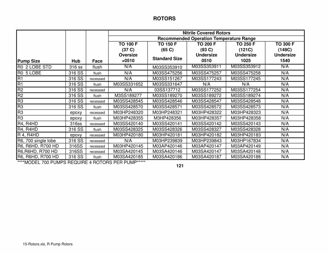
ROTORS
TO 100 F
(37 C)
TO 150 F
(65 C)
TO 200 F
(93 C)
TO 250 F
(121C)
TO 300 F
(149C)
Pump Size Hub Face
Oversize
+0510Standard Size
Undersize
0510
Undersize
1025
Undersize
1540
R0 2 LOBE STD 316 ss flush N/A M03SS353910 M03SS353911 M03SS353912 N/A
R0 5 LOBE 316 SS flush N/A M03SS475256 M03SS475257 M03SS475258 N/A
R1 316 SS recessed N/A M03SS151267 M03SS177243 M03SS177245 N/A
R1 316 SS flush M03SS331652 M03SS331647 N/A N/A N/A
R2 316 SS recessed N/A 03SS137712 M03SS177252 M03SS177254 N/A
R2 316 SS flush M3SS189277 M03SS189270 M03SS189272 M03SS189274 N/A
R3 316 SS recessed M03SS428545 M03SS428546 M03SS428547 M03SS428548 N/A
R3 316 SS flush M03SS428570 M03SS428571 M03SS428572 M03SS428573 N/A
R3 epoxy recessed M03HP248320 M03HP248321 M03HP428322 M03HP428323 N/A
R3 epoxy flush M03HP428355 M3HP428356 M03HP428357 M03HP428358 N/A
R4, R4HD 316ss recessed M03SS420140 M03SS420141 M03SS420142 M03SS420143 N/A
R4, R4HD 316 SS flush M03SS428325 M03SS428326 M03SS428327 M03SS428328 N/A
R 4, R4HD epoxy recessed M03HP420180 M03HP420181 M03HP420182 M03HP420183 N/A
R6, 700 single lobe 316 SS recessed N/A M03HP239839 M03HP239843 M03HP167834 N/A
R6, R6HD, R700 HD 316SS recessed M03HP420145 M03AP420146 M03AP420147 M03AP420149 N/A
R6,R6HD, R700 HD 316SS recessed M03SA420145 M03SA420146 M03SA420147 M03SA420148 N/AR6, R6HD, R700 HD 316 SS flush M03SA420185 M03SA420186 M03SA420187 M03SA420188 N/A
****MODEL 700 PUMPS REQUIRE 4 ROTORS PER PUMP*****
Nitrile Covered Rotors
Recommended Operation Temperature Range
121
15-Rotors.xls, R Pump Rotors

ROTORS
TO 100 F
(37 C)
TO 150 F
(65 C)
TO 200 F
(93 C)
TO 250 F
(121C)
TO 300 F
(149C)
Pump Size Hub Face
Oversize
+0510Standard Size
Undersize
0510
Undersize
1025
Undersize
1540
R0 316 SS flush N/A N/A N/A N/A N/A
R1 316SS recessed N/A N/A N/A N/A N/A
R1 316 SS flush N/A N/A N/A N/A N/A
R2 316 SS recessed N/A M03SS331657 M03SS331654 M03SS331656 M03SS331658R3 316SS recessed M03SS442625 M03SS442626 M03SS442627 M03SS442628 M03SS442629
R3 316 SS flush M03SS465735 M03SS465736 M03SS465737 M03SS465738 M03SS465739R3 epoxy recessed M03HP442125 M03HP442126 M03HP442127 M03HP442128 M03HP442129
R4, R4HD 316 SS recessed M03SS442630 M03SS442631 M03SS442632 M03SS442633 M03SS442634
R6, 700 single lobe 316 SS recessed M03HP475980 M03HP475981 M03HP475982 M03HP475983 M03HP475984
R6,R6HD, R700 HD 316SS recessed M03HP442635 M03HP442636 M03HP442637 M03HP442638 M03HP442639R6, R6HD, R700 HD 316 SS recessed M03SA442635 M03SA442636 M03SA442637 M03SA442638 M03SA442639
R6, R6HD, R700 HD 316 SS flush M03SA465745 M03SA465746 M03SA465747 M03SA465748 M03SA465749
TO 100 F
(37 C)
TO 150 F
(65 C)
TO 200 F
(93 C)
TO 250 F
(121C)
TO 300 F
(149C)
Pump Size Hub Face
Oversize
+0510Standard Size
Undersize
0510
Undersize
1025
Undersize
1540
R0 2 Lobe std 316 SS flush N/A M03SS469161 M03SS469162 M03SS469163 M03SS469164
R0 5 Lobe 316ss flush N/A M03SS492580 N/A N/A N/A
R1 316 SS recessed M03SS469180 M03SS469181 M03SS469182 M03SS469183 M03SS469184
R2 316 SS recessed M03SS469190 M03SS469191 M03SS469192 M03SS469193 M03SS469194
R3 316 SS recessed M03SS478210 M03SS478211 M03SS478212 M03SS478213 M03SS478214
R4, R4HD 316 SS recessed M03SS478215 M03SS478216 M03SS478217 M03SS478218 M03SS478219
R6, R6HD, R700 HD 316 SS recessed M03SA478220 M03SA478221 M03SA478222 M03SA478223 M03SA478224R6, 700 single lobe 316 SS recessed M03HP478225 M03HP478226 M03HP478227 M03HP478228 M03HP478229
HNBR Covered Rotors
Recommended Operation Temperature Range
EPDM Covered Rotors
Recommended Operation Temperature Range
122
15-Rotors.xls, R Pump Rotors

ROTORS
TO 100 F
(37 C)
TO 150 F
(65 C)
TO 200 F
(93 C)
TO 250 F
(121C)
TO 300 F
(149C)
Pump Size Hub Face
Oversize
+0510Standard Size
Undersize
0510
Undersize
1025
Undersize
1540
R0 2 Lobe std 316SS flush N/A M03SS469001 M03SS469002 M03SS469003 N/A
R0 5 Lobe 316SS flush N/A M03SS442440 M03SS830511 N/A N/A
R1 316SS recessed M03SS408285 M03SS408286 M03SS408287 M03SS408288 M03SS408289
R1 316SS flush M03SS469020 M03SS469021 M03SS469022 M03SS469023 M03SS469024
Solid Epoxy
Pump Size
0510 Undersize
TO 180 F
(82 C) Pump Size
TO 200 F
(93 C)
R0 N/A R0 N/A
R1 M03HP408337 R1 N/A
R2 M03HP475442 R2 N/A
R3 M03HP465722 R3 M03HP385221R4 N/A R4 M03HP382819
R6 N/A R6 M03HP361928
ONLY AVAIABLE IN SHOWN MODELS
N/A
Viton Covered Rotors
Recommended Operation Temperature Range
M03HP408336
Standard Size
TO 135 F
(57 C)
Solid Celcon
Flush Face
N/A
N/A
M03HP475441
M03HP465721
123
15-Rotors.xls, R Pump Rotors
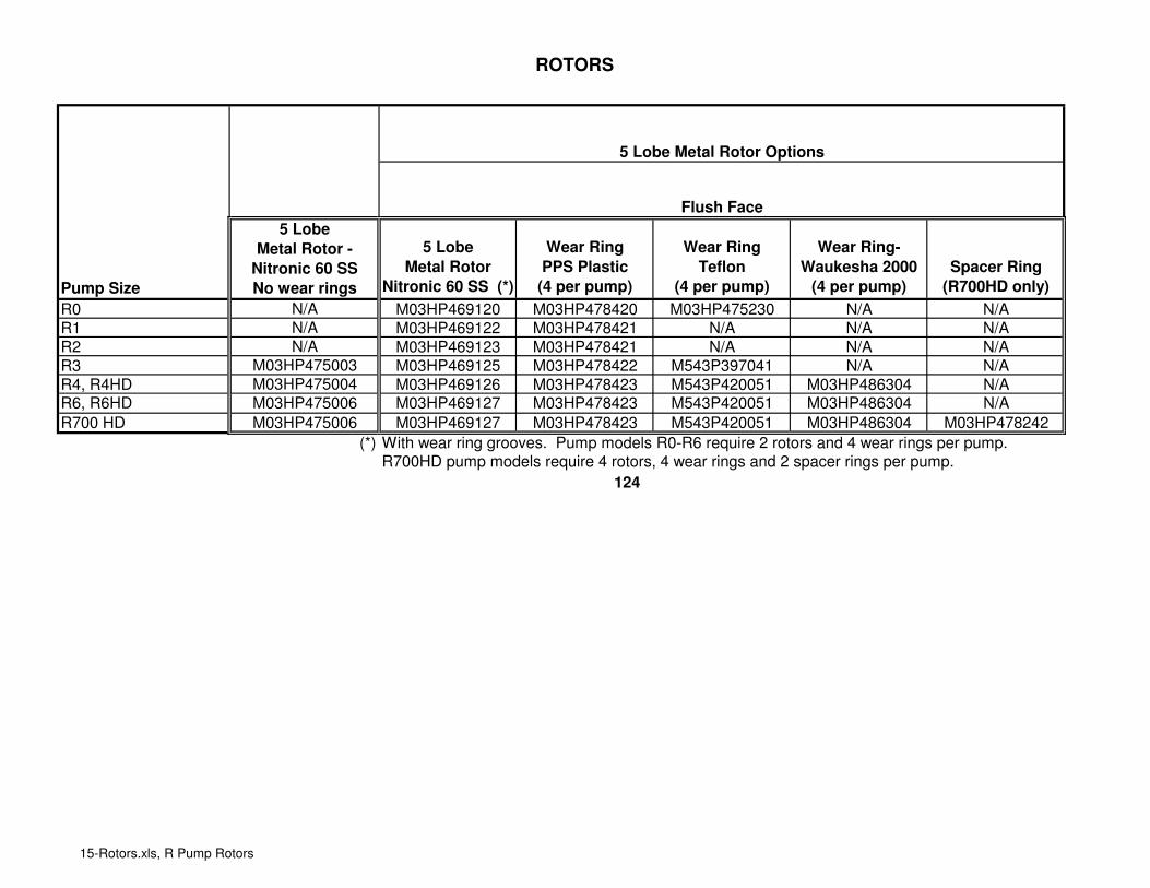
ROTORS
Pump Size
5 Lobe
Metal Rotor
Nitronic 60 SS (*)
Wear Ring
PPS Plastic
(4 per pump)
Wear Ring
Teflon
(4 per pump)
Wear Ring-
Waukesha 2000
(4 per pump)
Spacer Ring
(R700HD only)
R0 M03HP469120 M03HP478420 M03HP475230 N/A N/A
R1 M03HP469122 M03HP478421 N/A N/A N/A
R2 M03HP469123 M03HP478421 N/A N/A N/A
R3 M03HP469125 M03HP478422 M543P397041 N/A N/A
R4, R4HD M03HP469126 M03HP478423 M543P420051 M03HP486304 N/AR6, R6HD M03HP469127 M03HP478423 M543P420051 M03HP486304 N/A
R700 HD M03HP469127 M03HP478423 M543P420051 M03HP486304 M03HP478242
(*) With wear ring grooves. Pump models R0-R6 require 2 rotors and 4 wear rings per pump.R700HD pump models require 4 rotors, 4 wear rings and 2 spacer rings per pump.
5 Lobe
Metal Rotor -
Nitronic 60 SS
No wear rings
N/A
N/A
N/A
M03HP475003
M03HP475004
M03HP475006
M03HP475006
5 Lobe Metal Rotor Options
Flush Face
124
15-Rotors.xls, R Pump Rotors

ROTORS
Pump Size
2 Lobe Bow Tie
Metal Rotor
Nitronic 60 SS (*)
Wear Ring
PPS Plastic
(4 per pump)
Wear Ring
Teflon
(4 per pump)
Wear Ring-
Waukesha 2000
(4 per pump)
Spacer Ring
(R700HD only)
R0, R1, R2, R3 N/A N/A N/A N/A N/A
R4, R4HD M03HP481484 M03HP478423 M543P420051 M03HP486304 N/AR6, R6HD M03HP481486 M03HP478423 M543P420051 M03HP486304 N/A
R700 HD M03HP481486 03HP478423 M543P420051 M03HP486304 M03HP478242
(*) With wear ring grooves. Pump models R0-R6 require 2 rotors and 4 wear rings per pump.R700HD pump models require 4 rotors, 4 wear rings and 2 spacer rings per pump.
TO 100 F (37
C)
TO 150 F (65
C)
TO 200 F (93
C)
TO 250 F
(121C)
TO 300 F
(149C)
Pump Size Hub Face
Oversize
+0510Standard Size
Undersize
0510
Undersize
1025
Undersize
1540
R1 (JT) 316 SS recessed M03SS420120 M03SS420121 M03SS420122 M03SS420123 M03SS420124
R2 (JT) 316 SS recessed M03SS420125 M03SS420126 M03SS420127 M03SS420128 M03SS420129R3 (JT) 316 SS recessed M03SS475200 M03SS475201 M03SS475202 M03SS475203 M03SS475204
NOTE: JT Rotors have tighter tolerances and are intended for metering pump applications.
Recessed (Standard) Face
Flush Face
Metal Rotor Options - 2 Lobe - Bow Tie
Stainless Steel Hub/Nitrile Covered Rotors - JT Profile
M03HP475006
2 Lobe Bow Tie
Metal Rotor -
Nitronic 60 SS
No wear rings
N/A
M03HP475004
M03HP475006
125
15-Rotors.xls, R Pump Rotors

TOOLS FOR ALL MODEL R SERIES PUMPS
TOOLS Qty R0 R1/R2 R3 R3HD R4/R6 R700HD
1 SPANNER WRENCH 1 N/A M689S4177 M689S4178 M689S4178 M689S4178 M689S4178
2 ROTOR PULLER WRENCH (not HD pumps) 1 N/A N/A M03HP133586 N/A M03HP133613 N/A
3 T-HANDLE WRENCH 1 N/A M747P133540 N/A N/A N/A N/A
4 ROTOR PULLER - R0 1 M03AP367535 N/A N/A N/A N/A N/A
5 SEAL INSERTER 1 M03AP353666 M03AP286719 M03AP286600 M03AP286600 M03AP286752 M03AP286752
6 ROTOR PULLER - SOLID PLASTIC ROTOR 1 N/A N/A M03AP395466 M03AP395466 M03AP385820 N/A
7 ROTOR PULLER - 3 PRONG 1 N/A M03AP188155 M03AP225667 M03AP225667 N/A N/A
8
HEAVY DUTY ROTOR PULLER (HD pumps
only) 1 N/A N/A N/A N/A M03AP250898 M03AP221079
9
REPLACEMENT FINGER KIT - includes
finger, spacer and 3 screws 1 N/A N/A N/A N/A M03WP221081 M03WP221081
MODEL
126
16-Tools All.xls, Tools - R Pumps

R SERIES PUMPS - RECOMMENDED INVENTORY
Class I Duty - Suggested for domestic service and where some interruption in service is possible.
Supplies typical service part usage for 6 months or 1000 hours of service.
Class II Duty - Suggested for export service or for domestic service where minimum loss of service is essential.
Supplies typical service part usage for 1 year or 2000 hours.
Order by part number, not by item number.
Spare Parts are supplied with each pump, including some parts listed below.
Those items included are identified with ( ) and the quantity following the part description.
Class I Class II
Gear Case Parts
BEARING - Front - Tapered Roller All N/A 2
BEARING - Rear - Tapered Roller All N/A 2
BEARING Cover (R4HD, R6HD and R700HD models only) R4HD, 6HD, 700HD N/A 2
GASKET - Gear Case All 1 1
O-RING - Rear Bearing Seal All 10* 10*
SEAL - Front Oil All 2 2
SEAL - Rear Oil All 1 1
SHAFT & GEAR ASSEMBLY - Long All N/A 1
SHAFT & GEAR ASSEMBLY - Short All N/A 1
Product Contact Parts
BEARING - Seal All 4 8
BUSHING - HD Shaft (3HDRI only) 3HD, 3HDRI only 20* 20*
O-RING - Pump Seal (2) All 10* 20
ROTOR (Per Sold Order) All 4 4
SEAL - Shaft (Per Sold Order) (2) All 10* 20
GASKET - Cover (Paper) (100) all but R0 100 200
GASKET - Cover (O-ring) R0 & R's w/oring option 10* 20
O-RING - Front Cartridge R4HD, R6HD & R700HD Models 10* 20
O-RING - Rear Cartridge (R700 only) R700HD only 10* 20
Options (add only if option was selected)
WEAR RING - Solid Metal Rotor metal rotor option 10 20
SPACER RING - Solid Metal Rotor R700HD only 2 4
GASKET - Rectangular Inlet RI models 2 4
GASKET - Rectangular Cover (Paper) (In Place of Standard) RI models 100* 200
DEAERATOR/DEGASSER CARTRIDGE - Front (R700 only) R700HD only 2 N/A
WATER FLUSH CARTRIDGE - Front (R700 only) R700HD only N/A 2
O-RING - Waterflush water flush seal option 10 20
*Number listed represents minimum order quantity
Quantity
Description
127


APV, An SPX Brand611 Sugar Creek RoadDelavan, WI 53115Phone: (888) 278-4321Email: [email protected]
For more information about our worldwide locations, approvals, certifications, and local representatives, please visit www.apv.com.
SPX Corporation reserves the right to incorporate our latest design and material changes without notice or obligation.Design features, materials of construction and dimensional data, as described in this bulletin, are provided for your information only and should not be relied upon unless confirmed in writing.
Issued: 04/2009 03WP469240-I Copyright © 2008 SPX Corporation
Indianapolis ● Chicago ● San Juan www.hollandapt.com
800-800-8464