Embed Size (px)
Citation preview

Contents lists available at ScienceDirect
Applied Energy
journal homepage: www.elsevier.com/locate/apenergy
Post-combustion CO2 capture from a natural gas combined cycle powerplant using activated carbon adsorptionL. Jiang⁎, A. Gonzalez-Diaz⁎, J. Ling-Chin, A.P. Roskilly, A.J. SmallboneSir Joseph Swan Centre for Energy Research, Newcastle University, Newcastle, UK
H I G H L I G H T S
• Compared with monoethanolamine, net efficiency using activated carbon is improved.
• Heat regeneration of activated carbon is lower at higher CO2 concentration.
• Activated carbon is cost-competitive for CO2 capture in natural gas combined cycle.
• Adsorption carbon capture can be further improved using enhanced heat/mass recovery.
A R T I C L E I N F O
Keywords:Post-combustion CO2 captureNatural gas combined cycleAdsorptionAbsorptionEconomic analysis
A B S T R A C T
As fossil fuel power plants have emitted significant quantity of carbon dioxide (CO2) into the atmosphere whichaggravates climate change, capturing and storing such emissions is key to mitigate the issue. An adsorptionsystem based on a physical adsorbent i.e. activated carbon is first assessed to capture CO2 emissions from anatural gas combined cycle. Then a subcritical sequential supplementary firing combined cycle with CO2 captureis used to analyse the effect of CO2 concentration. Analyses are carried out in terms of power loss and thermalefficiency. To evaluate the advantages of post-combustion CO2 capture using activated carbon, results arecompared with systems using a commercial absorbent, i.e. monoethanolamine and a chemical adsorbent i.e.polyethyleneimine/silica. The net efficiency of natural gas combined cycle using activated carbon increasesslightly from 50.8% to 51.1% due to the lower regeneration temperature at 358 K. The performance of thesystem using PEI/silica is almost the same as that using activated carbon at 368 K. Although the thermal energyrequired to regenerate the activated carbon is relatively high, a significant improvement of net efficiency isobserved with increased partial pressure. Economic analysis indicates that the systems using activated carbon isa competitive alternative for CO2 capture. It is concluded activated carbon is relatively more advantageous thanmonoethanolamine in terms of efficiency and cost, which could be further improved with enhanced heat andmass recovery.
1. Introduction
In 2014, approximately 23% of carbon dioxide (CO2) emissionsemitted into the atmosphere was from fossil fuel power plants [1].Electricity production from fossil fuels is predicted to increase by about30% before 2035 [2]. Although renewable energy is increasingly uti-lised, electricity generation from natural gas is expected to remain asignificant global power source until at least 2030 [3], primarily due tothe lower capital cost and carbon intensity of the natural gas combinedcycle (NGCC) [4]. Carbon capture and storage (CCS) has the potentialand is recognised for the cost effective for reducing energy-relatedemissions in the power sector [5] where some operators of NGCC power
plants have started to consider CCS, although the current number ofapplications is still limited [3]. In addition, the potential of using CO2
for enhanced oil recovery (EOR) has been demonstrated due to itscheaper price and miscibility with crude oil compared to other misciblefluids [6]. It is estimated that the CO2 captured from the Petra Novaproject located in Texas has increased the daily oil production from 300barrels in 2017 to about 4000 barrels to date [7].
Exhaust gas from combustion processes contains CO2, which can becaptured using a range of solvents. The technology is referred to as post-combustion CO2 capture. As applied in coal power plants for both theBoundary Dam and Petra Nova projects, post-combustion CO2 captureusing amine is the first to reach a commercial scale and is currently the
https://doi.org/10.1016/j.apenergy.2019.04.006Received 20 December 2018; Received in revised form 18 March 2019; Accepted 7 April 2019
⁎ Corresponding authors.E-mail addresses: [email protected] (L. Jiang), [email protected] (A. Gonzalez-Diaz).
Applied Energy 245 (2019) 1–15
0306-2619/ © 2019 The Author(s). Published by Elsevier Ltd. This is an open access article under the CC BY-NC-ND license (http://creativecommons.org/licenses/BY-NC-ND/4.0/).
T

most advanced technology for capturing CO2 from power plants. This ismainly because of complementary industrial experience establishedfrom similar processes in, e.g. natural gas sweetening plants [8]. As oneof the main solvents used for post-combustion CO2 capture [9],monoethanolamine (MEA) is very reactive and can effectively remove ahigh volume of acid gas from flue gas. However, during solvent re-generation, MEA is very corrosive, requires a large quantity of energy,and forms components e.g. formaldehyde, acetic acid, hydro-xyacetaldehyde, glycolic acid, formic acid, oxalic acid etc. that cannotbe regenerated by thermal heat [10]. In a NGCC, excess air is necessaryfor the operation of the gas turbine, which results in a high con-centration of O2 in the gas turbine exhaust gas, i.e. around 15% v v−1.That consequently stimulates oxidative degradation of MEA and in-creases operational costs [11,12]. Another problem using MEA lies inthe low CO2 concentration. Some research studies have demonstratedthat the low CO2 concentration in the exhaust gas will increase theenergy required for regenerating the MEA solvent for a MEA-basedpost-combustion CO2 capture plant [13,14]. In a NGCC, CO2 is dilutedwith nitrogen (N2) which is supplied by 200–300% of excessive air[15,16]. Thus, several approaches, e.g. exhaust gas recirculation (EGR),selective exhaust gas recirculation (SEGR), subcritical sequential sup-plementary firing combined cycle (SSFCC) have been proposed for in-creased CO2 and reduced oxygen (O2) concentrations in a NGCC with
absorption-based post-combustion CO2 capture using MEA [17,18].Although EGR can increase CO2 concentration up to 6.7 mol% andimprove the net efficiency of the cycle by 0.5%, the concentration of O2
will decrease from 12mol% to 8.3mol% [19]. As a result, the problemwith amine degradation remains unsolved. Whilst SEGR presents thehighest increment of CO2 in the exhaust gas from 4mol% to 18.6mol%and the efficiency is increased by 0.5%, the concentration of O2 remainshigh [19]. Subcritical SSFCC increases CO2 concentration from 4.0mol% to 8.94mol% [19]. The volumetric flow is reduced by 50% ap-proximately, leading to the highest reduction in O2 concentration from12mol% to 1mol% [19]. It is worth noting that the quantities of CO2
and O2 mentioned previously are dependent on the assumptions madein Ref. [19], and therefore they are subject to change in line with theassumptions defined in a study. In other words, the performance ofthese absorption-based post-combustion CO2 capture approaches is af-fected by CO2 [20], which is usual around 3–4mol% [21].
Compared with absorption-based post-combustion CO2 capture,adsorption is a promising and versatile technique, and its performanceis not influenced by O2 concentration [22]. The advantages of adsorp-tion-based post-combustion CO2 capture technology include reducedcosts in CO2 separation, lower regeneration energy requirements, andminimised pressure losses, which ensure a relatively good performancein the process of capturing CO2 [23,24]. Operating methods (which
Nomenclature
A adsorption potential (J mol−1)AC activated carbonC specific heat capacity (kJ kg−1 K)CCS carbon capture and storageCEPCI chemical engineering plant cost indexCF capacity factorD-A Dubinin-AstakhovE characteristic energy (J mol−1)EGR exhaust gas recirculationEOR enhanced oil recoveryESA electric temperature swing adsorptionEx exergy (MW)FC fuel costFCF fixed charge factorFOM fixed operation and maintenance costH reaction heat (kJ−1 kg−1)HP high pressureHR heat rateHRSG heat recovery steam generatorLCOE levelised cost of electricityLHV low heat valueLP low pressurem mass (kg)MEA monoethanolamineMOF metal organic frameworkMP medium pressuren surface-structural heterogeneity factorNGCC natural gas combined cycleP pressure (Pa)PEI polyethyleneiminePSA pressure swing adsorptionq CO2 adsorption capacity (mg−1 g−1)Q heat (kJ)r interest rateR universal gas constant (8.314 J mol−1 K−1)RC reference cost (M$)RP reference caseSC scaled cost (M$)
SEGR selective exhaust gas recirculationSP scaled referenceSSFCC sequential supplementary firing combined cycleT temperature (°C)t time (s)TCO2 CO2 transport costTIC total investment costTL economic life of the plantTSA temperature swing adsorptionVOM variable operation and maintenance costVSA vacuum swing adsorptionW power output (kW)
Greek letter
η efficiency
Superscript
R scaling exponent of the capture plant
Subscripts
ad adsorptionau auxiliarycap captureCO2 carbon dioxidecom compressorde desorptione partialh regenerationhr heat recoveredin inputL latent heatLP low pressurep powerre reactorS sensible heatsat saturation
L. Jiang, et al. Applied Energy 245 (2019) 1–15
2

Fig. 1. The schematic diagram of combined cycle power plants integrated with an adsorption system in (a) a conventional NGCC power plant; and (b) a subcriticalSSFCC power plant [42].
L. Jiang, et al. Applied Energy 245 (2019) 1–15
3

correspond to different carbon capture cycles) and adsorbent materialsare two research hotspots affecting the performance of CO2 capture.Adsorption-based post-combustion CO2 capture can be classified intopressure swing adsorption (PSA) [25], vacuum swing adsorption (VSA)[26], temperature swing adsorption (TSA) [27] and electric tempera-ture swing adsorption (ESA) [28]. PSA operates above atmosphericpressure, VSA happens at atmospheric pressure whilst desorption takesplace under low pressure. During TSA, a desorber is heated by an ex-ternal heat source e.g. hot water whilst an adsorber is cooled by acooling medium e.g. cooling water. ESA is a type of TSA where elec-tricity is used for fast desorption. In the operating process, adsorptionand desorption happen alternatively to acquire high purity CO2. Thiscycle is intermittent, and therefore a second set of the adsorber and thedesorber is required to achieve continuous operation. Moving beds havebeen proposed as a regenerator but their heat transfer is poor, leadingto an undesirable overall performance [29]. Recently, fluidized bedswhich can continuously capture CO2 have been conceptually designedbut the performance of their amine-based adsorbent is yet to be ex-plored [30]. A novel carbon pump theory used for evaluating CO2
capture processes has been successfully applied to TSA, PSA, VSA andESA [28], which provides insights into the thermal performance of CCStechnologies [31,32]. Also, various solid adsorbents, which are classi-fied into physical and chemical adsorbents, can be selected for cap-turing CO2 in different applications [33]. Physical sorbents e.g. zeolite5A, zeolite 13X, activated carbon (AC) and silica gel have been widelyinvestigated for adsorption-based CO2 capture which are inexpensive,insensitive to moisture and with a large surface area [34,35]. Severalnovel physical adsorbents e.g. metal organic framework (MOF) haveattracted attention due to their large adsorption capacity and high gasselectivity [36]. Nevertheless, their costs are relatively high comparedto those of conventional adsorbents. As for chemical sorbents, amine-based materials are more advantageous due to their lower generationheat [37]. However, these materials have a similar degradation issuewith high O2 concentration [37]. It is worth noting that adsorptioninvestigations on CCS have been mainly focused on the characteristicsof materials. However, there is no research study on adsorption tech-nology using AC in a NGCC and a subcritical SSFCC. In this study, si-mulation for AC covering a range of desorption temperatures, have
been carried out. Thus, the novelty of this work relates in its applicationto work in the context and detail of a real-world application.
This paper is original as it aims to evaluate the performance of TSAtechnology using AC for post-combustion CO2 capture in NGCC andsubcritical SSFCC power plants, which has neither been investigatedpreviously nor covered in literature. AC is selected as the adsorbent forcapturing CO2 from flue gas, which is most commonly used for CO2
capture when adsorption characteristics, cost, sensitivity to moisture,thermal and mechanical stability are taken into consideration [38,39].Experimental results of previous research have demonstrated its feasi-bility for CO2 capture by using fluidized bed on top of reporting theeffect of CO2 partial pressure and superficial gas velocity [40]. Ad-sorption isotherms and reaction heat (H) of AC have been investigatedby various researchers, for instance [22,41] where the establishedthermal properties can be used for system design and optimisation ofCO2 capture. Desorption heat is calculated based on carbon pumptheory [31]. The overall performance of the NGCC integrated with TSAsystem using AC is compared with the systems using MEA and anotheramine-based adsorbent i.e. polyethyleneimine (PEI)/silica respectively.How CO2 concentration of the flue gas affects regeneration heat is alsoevaluated by using the SSFCC as a case study to show the advantages ofAC in dealing with flue gas which has high CO2 concentration. Theframework of this paper is as follows. The novel system is introduced inSection 2 where both power generation and CO2 capture cycles are il-lustrated. Then methodology applied in the study is presented inSection 3. Section 4 shows simulation results and analysis, followed byconclusions in Section 5.
2. Power plants with carbon capture
2.1. System description
A schematic diagram of the NGCC integrated with TSA is shown inFig. 1(a). The power generation system is composed of a 9FB GeneralElectric gas turbine with a heat recovery steam generator (HRSG), and asteam turbine. The steam produced in the HRSG flows into the steamturbine to generate power. Three pressure levels of steam are generatedin the HRSG, i.e. high, medium and low steam pressure which
Fig. 2. Steam turbine diagrams showing thermal processes of (a) the NGCC; and (b) the SSFCC.
L. Jiang, et al. Applied Energy 245 (2019) 1–15
4
corresponds to the high pressure (HP), medium pressure (MP) and lowpressure (LP) turbines respectively. Unlike the NGCC using MEA wherethermal energy for regeneration is extracted from the crossover pipe,steam required for desorption of AC is extracted from the LP steamturbine. As desorption temperature is lower than 105 °C, low-gradesteam or hot water can be used as the heat source.
Similarly, a schematic diagram of the SSFCC is presented inFig. 1(b). The power generation system is composed of a 9FB GeneralElectric gas turbine with HRSG, and a steam turbine. Only high pressuresteam is generated in the HRSG. A detailed SSFCC process could refer toReference [42]. It is indicated that the main difference between theSSFCC and the NGCC lies in the HRSG. Sequential combustion reducesO2 concentration and generates additional CO2 in flue gas. Supple-mentary firing in each step is limited by keeping the flue gas tem-perature after each duct burner to approximately 820 °C. Fuel is burnedin five steps through the HRSG, resulting in an improved power outputbut reduced efficiency. The last stage brings O2 around to the stoi-chiometric limit i.e. approximately 1% v v−1. Although the efficiency islower than that of the conventional NGCC, the increment in the poweroutput of the combined steam cycle leads a reduction of gas turbines, ata similar power output generated for a conventional NGCC. This leadsto a lower investment cost of the post-combustion CO2 capture plant.For countries with cheap natural gas i.e. $ 2–4 per million BritishThermal Unit (MMBTU), the SSFCC presents a marginal reduction onthe levelised cost of electricity (LCOE) as reported by Reference [42].
The concept design and feasibility of this adsorption-based CO2
capture system is detailed in Reference [30]. The system mainly con-sists of a cooler, an adsorber, a desorber, a cyclone and a compressor, asshown in Fig. 1(a) and (b). A circulating fluidized bed is adopted as theadsorber whilst a bubbling fluidized bed is chosen as the desorber. Thisintegrated compact system enables the adsorbent to be continuouslycirculated in a closed loop. Flue gas is first cooled by cooling water.Then CO2 in the flue gas is adsorbed by solid adsorbents. The cyclone isused to capture the adsorbent entrained by the adsorber while the CO2
free flue gas is released into the atmosphere through the stack. Theadsorbent is regenerated in the desorber by using thermal heat from thepower plant. The high purity CO2 is collected at the exit, compressed,transported and stored away. Similar to MEA, the solid adsorbent usedin the system is also recirculated in a closed loop. During desorption,energy required by AC is determined based on its basic properties. Thefluidized reactor is used for the adsorber and the desorber. A centrifugalcompressor, with a pressure ratio of 80, is used to compress CO2 toapproximately 150 bar for EOR application. The compression systemconsists of seven stages; each involves inter-cooling and water removal
equipment. The compressor is simulated in Aspen plus.
2.2. Thermal cycles
Steam from an extraction of the LP steam turbine instead of thecrossover pipe of the steam cycle is used to regenerate AC. Fig. 2(a) and(b) show thermal processes of the NGCC and the SSFCC respectively (asindicated by the underlying blue lines) and steam extraction to re-generate the amine solvent (i.e. the red dotted lines). As the tempera-ture/heat diagram for heat recovery steam generator (HRSG) is typicaland common, see [42,43], detailed illustration is not further presentedhere.
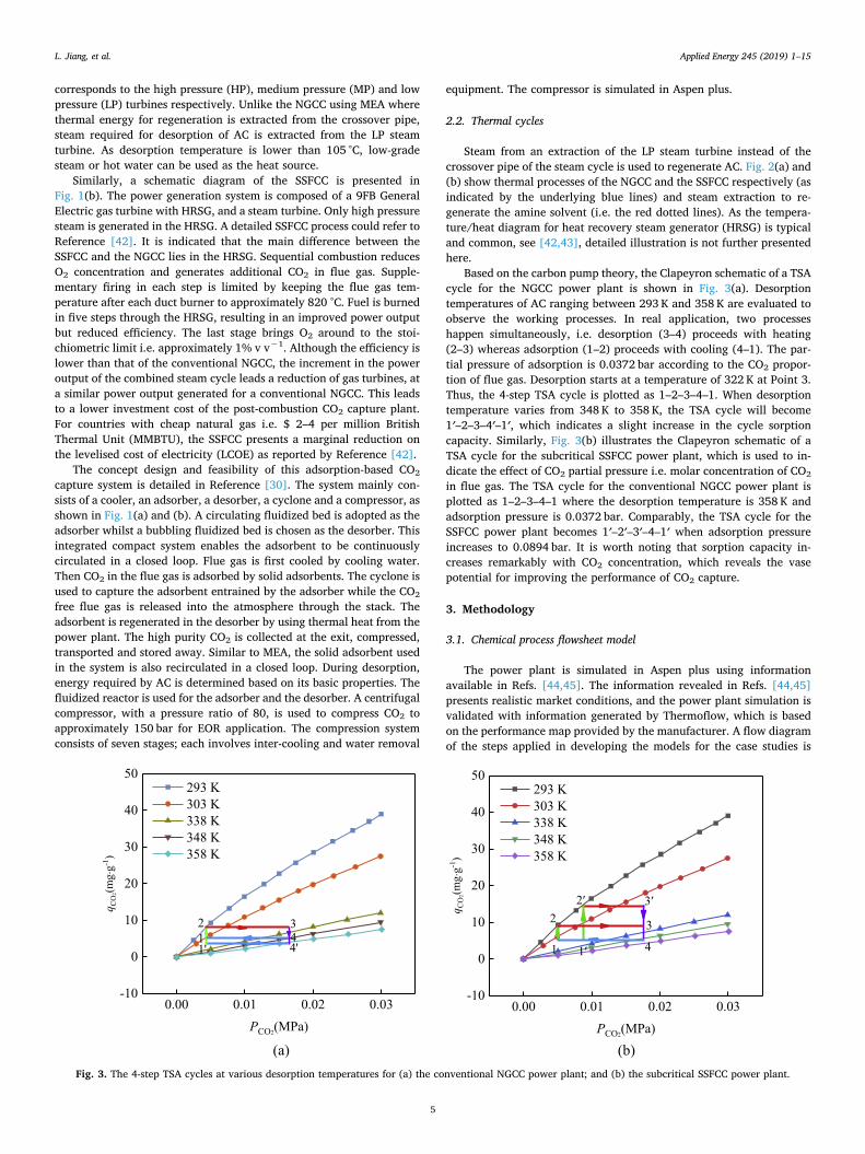
Based on the carbon pump theory, the Clapeyron schematic of a TSAcycle for the NGCC power plant is shown in Fig. 3(a). Desorptiontemperatures of AC ranging between 293 K and 358 K are evaluated toobserve the working processes. In real application, two processeshappen simultaneously, i.e. desorption (3–4) proceeds with heating(2–3) whereas adsorption (1–2) proceeds with cooling (4–1). The par-tial pressure of adsorption is 0.0372 bar according to the CO2 propor-tion of flue gas. Desorption starts at a temperature of 322 K at Point 3.Thus, the 4-step TSA cycle is plotted as 1–2–3–4–1. When desorptiontemperature varies from 348 K to 358 K, the TSA cycle will become1′–2–3–4′–1′, which indicates a slight increase in the cycle sorptioncapacity. Similarly, Fig. 3(b) illustrates the Clapeyron schematic of aTSA cycle for the subcritical SSFCC power plant, which is used to in-dicate the effect of CO2 partial pressure i.e. molar concentration of CO2
in flue gas. The TSA cycle for the conventional NGCC power plant isplotted as 1–2–3–4–1 where the desorption temperature is 358 K andadsorption pressure is 0.0372 bar. Comparably, the TSA cycle for theSSFCC power plant becomes 1′–2′–3′–4–1′ when adsorption pressureincreases to 0.0894 bar. It is worth noting that sorption capacity in-creases remarkably with CO2 concentration, which reveals the vasepotential for improving the performance of CO2 capture.
3. Methodology
3.1. Chemical process flowsheet model
The power plant is simulated in Aspen plus using informationavailable in Refs. [44,45]. The information revealed in Refs. [44,45]presents realistic market conditions, and the power plant simulation isvalidated with information generated by Thermoflow, which is basedon the performance map provided by the manufacturer. A flow diagramof the steps applied in developing the models for the case studies is
Fig. 3. The 4-step TSA cycles at various desorption temperatures for (a) the conventional NGCC power plant; and (b) the subcritical SSFCC power plant.
L. Jiang, et al. Applied Energy 245 (2019) 1–15
5

shown in Fig. 4. The base methods used in the simulation are Peng-Robinson for gaseous phase parameters [46] and Aspen Plus libraries(stmnbs2) which can be applied to calculate thermodynamic propertiesof water and steam. Steam required for regenerating AC is extractedfrom the LP steam turbine at 150 °C and 1.2 bar. Schematic diagrams ofAspen plus simulation are shown in Fig. 5(a) and (b) for the NGCC andthe subcritical SSFCC respectively. Due to confidentiality, it is im-possible to disclose commercial data of CO2 capture plants (amines andactivated carbon at industrial site). Therefore, the validation of thisstudy, like many others in literature, is carried out based on a com-parison in modelling presented in literature. In the case of the powerplant without CO2 capture, comparison is carried out using informationavailable in Thermoflow™, which is a software suite that mainly con-sists of GT PRO, GT MASTER and Thermoflex software. GT PRO is theleading gas turbine and combined cycle modelling software used byelectricity generation industry. It represents realistic market conditionsas it offers gas turbine databases with mapped performance curves. Themain reason of simulating the NGCC in Thermoflow is to ensure all casestudies could be performed using the same platform where all modelscan be easily developed and modified in Aspen Plus. The same powerplant, flue gas and CO2 concentration are used in the NGCC with CO2
capture using MEA and AC. Similarly, all the key boundary conditionsapplied for the SSFCC with CO2 capture using MEA and AC includingthe capture level of 90%, as well as water and environmental conditionshave been kept the same. With this, the comparison is conducted on afair platform and boundary conditions are equal. The schematic dia-grams of the NGCC and SSFCC simulated in Aspen Plus are shown inFig. 5.
3.2. Performance evaluation
The results of MEA system are obtained from Aspen Plus software(version 9) where the capture plant has been modelled using 30wt%MEA solvent. The methodology to optimise the design of the CO2
capture plant is summarised as follows [42]:
(1) The lean solvent loading of the MEA solution is manipulated to findthe minimum energy required in the reboiler to regenerate thesolvent.
(2) To study the effect of different lean loadings, the pressure of thestripper section of the reboiler is manipulated whilst temperature iskept constant at 120 °C [47].
(3) Finally, to achieve 90% of CO2 capture, the circulation rate of theMEA solvent is varied.
The capacity of one train is defined as 331 kg s−1. To cover the totalflue gas of the NGCC, two trains are required.
The performance evaluation of this study focuses on the adsorptionprocess as the performance of the NGCC has been widely assessed inprevious researches. For adsorption and desorption processes, equili-brium reactions are considered for AC as the total system efficiency isthe main subject of investigation in this study. For post-combustion CO2
capture using AC, the nonlinear expression of a Dubinin-Astakhov (D-A)model is applied to evaluate sorption capacity (q), as shown in Eq. (1).Relevant important parameters i.e. the limiting volumetric adsorptioncapacity (q0), characteristic energy (E), and the surface-structural het-erogeneity factor of adsorbents (n) are evaluated using adsorptionisotherms data. The above parameters used for the D-A model in thispaper can refer to Refs. [22,48]. The CO2 capture rate is defined as90%.
= ( )qqv
ea
AE0
n
(1)
where va and A are the specific volume of CO2 during the adsorbedphase and the adsorption potential, which are defined by Eqs. (2) [49]and (3) respectively:
=v v ea tT T( )t (2)
where vt and Tt are the specific volume and the temperature of liquidCO2, T is the working temperature (K), and α is the thermal expansioncoefficient [50]; and
=A RTln PPsat
e (3)
where R is the universal gas constant (8.314 J mol−1 K−1), Psat and Peare saturation and partial pressure of CO2 (MPa).
The adsorption isotherm data of AC are adopted from Ref. [51]detailing physical properties such as E, n, q0 and specific heat capacityCp, AC, i.e. 4957.9 J mol−1, 1.24, 1.1× 10⁻⁶ m3 g−1 and 825 J kg−1
K−1 respectively.The adsorption isotherm model is conducive to the TSA perfor-
mance evaluation. The following description is based on the TSA cyclesshown in Fig. 3(a) and (b). The regeneration heat, Qh (per kg of
Fig. 4. A flow diagram of the steps to develop the models of the case studies.
L. Jiang, et al. Applied Energy 245 (2019) 1–15
6

captured CO2) is estimated using Eq. (4) which is composed of bothsensible (QS) and latent heat (QL).
= +Q Q Qq q
( )( )h
s L
3 4 (4)
where q3 and q4 are sorption capacities according to Points 3 and 4 inFig. 3(a) and (b), respectively. QS can be expressed as Eq. (5):
= + +Q C dT q C dT qC dTT
Tp AC T
Tp a T
Tp as , 3 , ,
2
4
2
3
3
4
(5)
where Cp,AC and Cp,a are the specific heat capacity of AC and the ad-sorbed CO2, respectively.QL can be determined using Eq. (6), as follows:
= =Q H dq H q q( )ad T
TadL 3 4
3
4
(6)
where Had is the reaction heat of the adsorbent. QS includes the sensibleheat of the adsorbent (QS, ad) and the sensible heat of the CO2 adsorbedgas phase (QS, CO2) during preheating and desorption respectively.Thus, to determine Qh, Eq. (4) can be transformed into Eq. (7), as fol-lows:
= + + = +
+
( ) ( )Q Q Q Q q q Q Q q q
H
/( ) /( )
ad
h s, CO s, ad L,ad 3 4 s, CO s, ad 3 42 2
(7)
where QL, ad is the latent heat of the adsorbent. The exergy of Qh (Exh)can be presented as Eq. (8):
=Ex Q TT
1h
h h0
(8)
where T0 and Th are ambient and heating temperatures, respectively.The net power plant efficiency (η) is a key factor to assess the
economic performance of a power plant with and without a CO2 cap-ture system. For a power plant without CO2 capture, it is usually de-fined as the percentage of the total thermal energy input of natural gaswhich is converted into electricity, as shown in Eq. (9):
= =W tQ
W W tQ
x100%( )
x100%net
in
p au
in (9)
whereWnet is the net power output of the NGCC; Qin is the total thermalenergy input; Wp is the gross power output from turbines; Wau is thetotal auxiliary loads including plant operation, energy consumption andthe losses of transformers; and t is the length of period. For the NGCC
(a)
Turbine
HPS3 HPS4
RH1
HP Turbine MP Turbine
HPS0
Compressor
LP Turbine Condenser
PS2 MPS1 PS
HPE
PE3LPE
IPE1
DAB LTE
(b)
Compressor
Turbine
Combustor
B4 B23
B6
B9
RH3
B11 B12 B2 B3 B5
B8
B13 B14 B15
Fig. 5. The Aspen plus models of (a) the conventional NGCC; and (b) the subcritical SSFCC power plants; both are integrated with an adsorption-based CO2 capturesystem.
L. Jiang, et al. Applied Energy 245 (2019) 1–15
7

integrated with CO2 capture, η can be expressed as Eq. (10).
= =W tQ
W W W W tQ
( )net
in
p au cap com
in (10)
where Wcap is the loss in power output due to steam extraction andelectricity consumption required for the CO2 capture system; and Wcom
is the electricity required to compress the captured CO2 to the desiredpressure for transportation and storage.
4. Results and discussion
4.1. Energy and exergy analysis of the NGCC with TSA
Fig. 6 shows the trends of Qh for CO2 capture systems using ACwhen desorption temperature increases from 348 K to 378 K, MEA at393 K and PEI/silica at 403 K respectively. The regeneration heat ofPEI/silica could refer to Ref. [30] which mainly depends on the CO2
concentration in the flue gas. In spite of the difference of CO2 con-centration between this study and Reference [30], it has marginal in-fluence on the comparative results e.g. power loss and net efficiency. Itis found that Qh for the CO2 capture system using AC decreases withdesorption temperature. The reasons are explained as follows. Forphysical adsorbents, e.g. AC and zeolite, QS constitutes a major pro-portion of Qh when compared with QL. Since adsorption capacity in-creases with temperature, the ratio of QS to Qh decreases. The resultsreveal that Qh of the CO2 capture system using AC ranges from 4.91 GJtonne CO2
−1 to 5.81 GJ tonne CO2−1, which is in agreement with the
range of 4.65–13.96 GJ tonne CO2−1 presented by Refs. [52,53] for
carbon-based sorbents. Compared with MEA and PEI/silica, the differ-ence in Qh can reach up to 3.3 GJ tonne CO2
−1. Similarly, hot fluid e.g.stream extracted from the LP steam turbine is indicated for differentdesorption temperatures as shown in Fig. 7. When temperature in-creases from 348 K to 378 K, the quantity of hot fluid extracted from theNGCC using AC decreases at a rate ranging 259–307 tonne h−1. Thestream from PEI/silica shows a minimum use which is lower than theCO2 capture system using MEA and much lower than that using AC.
Qh and desorption temperature vary with the choice of sorbents. ACoffers much higher Qh because of its lower adsorption capacity com-pared with MEA and PEI/silica which involve higher adsorption capa-cities. The advantage of using AC is that steam/hot water at lowertemperatures and pressure can be used due to its low regenerationtemperature, leading to reduced losses in power and energy efficiency.Power losses of the NGCC with CO2 capture system using AC arecompared with the conventional power plant with CO2 capture systemsusing MEA and PEI/silica respectively, as shown in Fig. 8. The losses aredue to CO2 compression, LP power output loss during steam extractionand auxiliaries for the capture plant, and power plant auxiliaries. Al-though Qh of AC is higher than that of MEA and PEI/silica, as men-tioned previously, AC used steam at lower temperatures and pressure.As a result, AC presents power losses for steam extraction which arealmost similar with PEI/silica but less than those of MEA. Based on thepower losses shown in Fig. 8, the efficiency of the NGCC with CO2
capture system is presented in Fig. 9. The maximum capacity that canbe extracted from the LP steam turbine is limited by the mass flow ofthe steam that is supplied to the LP steam turbine i.e. 375.6 tonne h−1.The results also show that the net efficiency of the NGCC with CO2
capture system using AC increases from 50.5% to 50.9% when theadsorption temperature rises from 348 K to 378 K. Meanwhile, the re-sult for the CO2 capture system using PEI/silica is almost the same asthat using AC at 368 K. The improvement of the net efficiency of theCO2 capture system using AC can reach up to 3% when compared withthat using commercial MEA.
To further illustrate the advantage and disadvantage of CO2 captureusing AC, an exergy analysis is conducted and the results are shown inFig. 10, which reflects the quality of heat extracted from the LP turbine
of the NGCC. The heat extracted from the NGCC with CO2 capturesystem using AC has much lower exergy than that from the NGCC withCO2 capture systems using MEA and PEI/silica, resulting in higher neteffieciency of the NGCC with CO2 capture system using AC, though Qhof the NGCC with CO2 capture system using AC is also much higherthan the systems using MEA and PEI/silica. Results show that the lar-gest exergy of the system using AC can be reduced by approximately23MW at 378 K and 11MW at 348 K respectively when compared withthe alternatives of using MEA and PEI/silica, which reveals the poten-tial of the NGCC with adsorption-based CO2 capture system using AC.
To understand different post-combustion CO2 capture systems forthe NGCC, some key parameters are presented in Table 1. The netpower output of the NGCC with absorption-based post-combustion CO2
capture using MEA is 368.85MW. Because of a lower desoption tem-perature i.e. 85 °C, the net power output of the CO2 capture systemusing AC increases by 2.76% and reaches 377.6MW, which offers thehighest efficiency i.e. 51.09% compared to 49.67% and 50.82% for thealternatives of using MEA and PEI/silica, respectively. Detailed para-meters of the HRSG of the NGCC are presented in Apendix, Table A1.
4.2. Energy analysis of the SSFCC with TSA
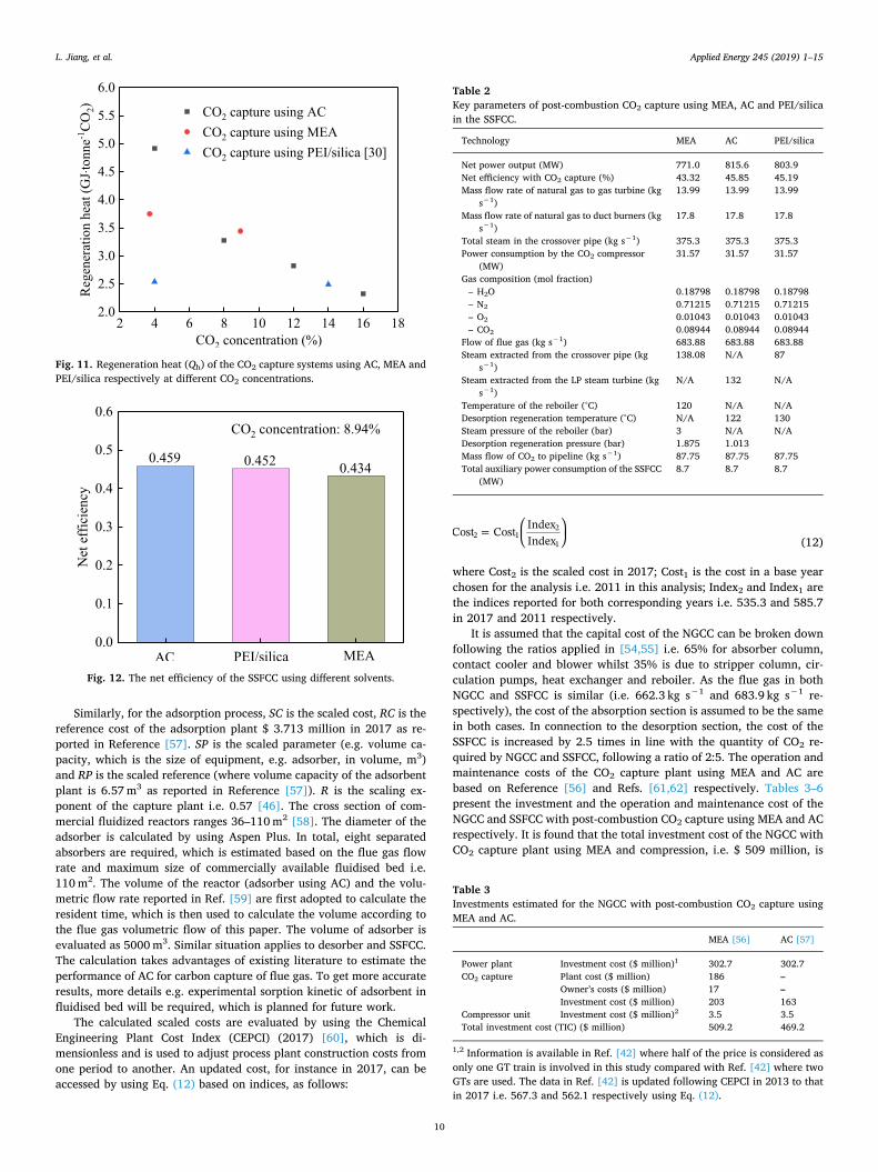
Fig. 11 presents the effect of CO2 concentration on the adsorptionsystems using AC, MEA and PEI/silica respectively. The results indicatethat higher partial pressure of CO2 in the flue gas would have a positiveeffect on the Qh of AC. Comparably, the generation heat of MEA isdecreased by 8.3% from 3.75 GJ tonne CO2
−1 at 3.72% of CO2 con-centration to 3.44 GJ tonne CO2
−1 at 8.94%. When AC is used tosubstitute for MEA, Qh is reduced by 33.3% from 4.92 GJ tonne CO2
−1
to 3.28 GJ tonne CO2−1 when CO2 concentration varies from 3.72% to
8.94%. The Qh of PEI/silica decreases by 2% from 2.54 GJ tonne CO2−1
at 4% of CO2 concentration to 2.49 GJ tonne CO2−1 at 14% [30]. It can
be noted that AC is more sensitive to CO2 concentration.It is recognised that the SSFCC is an alternative to increase the CO2
concentration in flue gas. In this study, CO2 concentration rises from3.72% (NGCC) to 8.94% (SSFCC) when supplementary firing is in-corporated. Fig. 12 shows the net efficiency of the SSFCCs using dif-ferent adsorbents. It is found that the net efficiencies of the SSFCCsusing AC and PEI/silica are quite close, which are higher than thatusing MEA. Although the net efficiency of the SSFCC using AC is slightlylower in comparison with that of the NGCC, it could be improved by8.2% when compared to that using MEA i.e. 43.32%. The key para-meters and the performance of the SSFCCs are also presented in Table 2.It is possible to increase the total power output from 771MW to
Fig. 6. Regeneration heat (Qh) of the CO2 capture system using AC vs. deso-rption temperatures.
L. Jiang, et al. Applied Energy 245 (2019) 1–15
8

815.9MW using AC, and the main advantage is the possibility to em-ploy low-grade steam in the application. Detailed parameters of theHRSG of the SSFCC are presented in Apendix, Table A2.
4.3. Economic assessment
As the main difference of the NGCC with CO2 capture systems usingMEA or AC lies in the capital cost of CO2 capture process, the costs ofpost-combustion CO2 capture using MEA and AC are analysed. The totalplant cost of the CO2 capture system using MEA for the NGCC is cal-culated by scaling up the cost indicated in Refs. [54,55], as expressed inEq. (11):
=SC RC SPRP
R
(11)
where SC represents a scaled cost; RC denotes a reference cost for theCO2 capture plant i.e. $181 million in 2011 as reported by Ref. [56]; SPand RP are parameters chosen for the scaled and the reference cases(e.g. flows, volume etc.). In this case, the flow of flue gas to the CO2
capture plant is 662.33 kg s−1, see Table 1. R is a scaling exponent ofthe capture plant i.e. 0.61.
Fig. 7. Hot fluid extracted from the LP steam turbine vs. desorption tempera-tures.
Fig. 8. Power losses of the NGCC with CO2 capture systems using AC, MEA andPEI/silica at different desorption temperatures.
Fig. 9. The net efficiency of the NGCC vs. desorption temperatures.
Fig. 10. Exergy of the steam used for regeneration at different desorptiontemperatures.
Table 1Key parameters of post-combustion CO2 capture using adsorption technologyand MEA in NGCC.
Technology MEA AC PEI/silica
Net power output without CO2 capture (MW) 411.62 411.62 411.62Net power output with CO2 capture (MW) 368.85 377.61 377.00Net efficiency without CO2 capture (%) 56.34 56.34 56.34Net efficiency with CO2 capture (%) 49.67 51.09 50.82Mass flow rate of natural gas to gas turbine (kg
s−1)13.99 13.99 13.99
Total steam in the crossover pipe (kg s−1) 104.4 104.4 104.4Power consumption by the CO2 compressor (MW) 10.67 10.67 10.67Gas composition (mol fraction)– H2O 0.0841 0.0841 0.0841– N2 0.7529 0.7529 0.7529– O2 0.1257 0.1257 0.1257– CO2 0.0372 0.0372 0.0372
Flow of flue gas (kg s−1) 662.3 662.3 662.3Temperature of flue gas (°C) 110.69 110.69 110.69Steam extracted from the crossover pipe (kg s−1) 59.8 N/A 53Steam extracted from the LP steam turbine (kg
s−1)N/A 72.1 N/A
Temperature of the reboiler (°C) 120 N/A N/ADesorption regeneration temperature (°C) N/A 85 130Steam pressure of the reboiler (bar) 3 N/A N/ADesorption regeneration pressure (bar) 1.898 1.013Mass flow of CO2 to pipeline (kg s−1) 35.15 35.15 35.15Total auxiliary power consumption of the NGCC
(MW)8.57 8.57 8.57
L. Jiang, et al. Applied Energy 245 (2019) 1–15
9
Similarly, for the adsorption process, SC is the scaled cost, RC is thereference cost of the adsorption plant $ 3.713 million in 2017 as re-ported in Reference [57]. SP is the scaled parameter (e.g. volume ca-pacity, which is the size of equipment, e.g. adsorber, in volume, m3)and RP is the scaled reference (where volume capacity of the adsorbentplant is 6.57m3 as reported in Reference [57]). R is the scaling ex-ponent of the capture plant i.e. 0.57 [46]. The cross section of com-mercial fluidized reactors ranges 36–110m2 [58]. The diameter of theadsorber is calculated by using Aspen Plus. In total, eight separatedabsorbers are required, which is estimated based on the flue gas flowrate and maximum size of commercially available fluidised bed i.e.110m2. The volume of the reactor (adsorber using AC) and the volu-metric flow rate reported in Ref. [59] are first adopted to calculate theresident time, which is then used to calculate the volume according tothe flue gas volumetric flow of this paper. The volume of adsorber isevaluated as 5000m3. Similar situation applies to desorber and SSFCC.The calculation takes advantages of existing literature to estimate theperformance of AC for carbon capture of flue gas. To get more accurateresults, more details e.g. experimental sorption kinetic of adsorbent influidised bed will be required, which is planned for future work.
The calculated scaled costs are evaluated by using the ChemicalEngineering Plant Cost Index (CEPCI) (2017) [60], which is di-mensionless and is used to adjust process plant construction costs fromone period to another. An updated cost, for instance in 2017, can beaccessed by using Eq. (12) based on indices, as follows:
=Cost Cost IndexIndex2 1
2
1 (12)
where Cost2 is the scaled cost in 2017; Cost1 is the cost in a base yearchosen for the analysis i.e. 2011 in this analysis; Index2 and Index1 arethe indices reported for both corresponding years i.e. 535.3 and 585.7in 2017 and 2011 respectively.
It is assumed that the capital cost of the NGCC can be broken downfollowing the ratios applied in [54,55] i.e. 65% for absorber column,contact cooler and blower whilst 35% is due to stripper column, cir-culation pumps, heat exchanger and reboiler. As the flue gas in bothNGCC and SSFCC is similar (i.e. 662.3 kg s−1 and 683.9 kg s−1 re-spectively), the cost of the absorption section is assumed to be the samein both cases. In connection to the desorption section, the cost of theSSFCC is increased by 2.5 times in line with the quantity of CO2 re-quired by NGCC and SSFCC, following a ratio of 2:5. The operation andmaintenance costs of the CO2 capture plant using MEA and AC arebased on Reference [56] and Refs. [61,62] respectively. Tables 3–6present the investment and the operation and maintenance cost of theNGCC and SSFCC with post-combustion CO2 capture using MEA and ACrespectively. It is found that the total investment cost of the NGCC withCO2 capture plant using MEA and compression, i.e. $ 509 million, is
Fig. 11. Regeneration heat (Qh) of the CO2 capture systems using AC, MEA andPEI/silica respectively at different CO2 concentrations.
Fig. 12. The net efficiency of the SSFCC using different solvents.
Table 2Key parameters of post-combustion CO2 capture using MEA, AC and PEI/silicain the SSFCC.
Technology MEA AC PEI/silica
Net power output (MW) 771.0 815.6 803.9Net efficiency with CO2 capture (%) 43.32 45.85 45.19Mass flow rate of natural gas to gas turbine (kg
s−1)13.99 13.99 13.99
Mass flow rate of natural gas to duct burners (kgs−1)
17.8 17.8 17.8
Total steam in the crossover pipe (kg s−1) 375.3 375.3 375.3Power consumption by the CO2 compressor
(MW)31.57 31.57 31.57
Gas composition (mol fraction)– H2O 0.18798 0.18798 0.18798– N2 0.71215 0.71215 0.71215– O2 0.01043 0.01043 0.01043– CO2 0.08944 0.08944 0.08944
Flow of flue gas (kg s−1) 683.88 683.88 683.88Steam extracted from the crossover pipe (kg
s−1)138.08 N/A 87
Steam extracted from the LP steam turbine (kgs−1)
N/A 132 N/A
Temperature of the reboiler (°C) 120 N/A N/ADesorption regeneration temperature (°C) N/A 122 130Steam pressure of the reboiler (bar) 3 N/A N/ADesorption regeneration pressure (bar) 1.875 1.013Mass flow of CO2 to pipeline (kg s−1) 87.75 87.75 87.75Total auxiliary power consumption of the SSFCC
(MW)8.7 8.7 8.7
Table 3Investments estimated for the NGCC with post-combustion CO2 capture usingMEA and AC.
MEA [56] AC [57]
Power plant Investment cost ($ million)1 302.7 302.7CO2 capture Plant cost ($ million) 186 –
Owner’s costs ($ million) 17 –Investment cost ($ million) 203 163
Compressor unit Investment cost ($ million)2 3.5 3.5Total investment cost (TIC) ($ million) 509.2 469.2
1,2 Information is available in Ref. [42] where half of the price is considered asonly one GT train is involved in this study compared with Ref. [42] where twoGTs are used. The data in Ref. [42] is updated following CEPCI in 2013 to thatin 2017 i.e. 567.3 and 562.1 respectively using Eq. (12).
L. Jiang, et al. Applied Energy 245 (2019) 1–15
10

8.53% higher than that using AC. For SSFCC with CO2 capture using ACand compressor, r the total investment is $ 509 million, i.e. 17.15%higher than that using AC. The operation and maintenance cost of thepower plants with CO2 capture process using AC is higher than that ofusing MEA for both NGCC and SSFCC. As a result, the total costs (in-cluding investment, operation and maintenance) of the NGCC with CO2
capture using MEA and AC are $ 534.3 million and $ 501.1 million; and$ 913.3 million and $ 791.6 million for the SSFCC, respectively. Bothcosts are in agreement with the estimate presented in Ref. [63]. It canbe concluded that CO2 capture using AC is more competitive from aneconomic perspective.
The following conditions apply in this study in estimating the LCOEof the power plant (including compression units):
• The gas price is fixed as $5 MMBTU−1.• CO2 is used for EOR whilst no storage cost is considered.• CO2 is sold at a price of $20 tonne CO2
−1 (in reality, the price willbe fluctuated with oil prices but this is not taken into considerationin this study).
• Carbon price associated with the residual carbon emissions is un-available.
• A total 8000 operating hours per year.• An annual factor of 10.6%.• A low heat value (LHV) is 51.8MJ kg−1.
The formulas used to estimate LCOE in this work are simplified aspresented by Eqs. (13) and (14) [67].
= × +× ×
+ + × +LCOE TIC FCF FOMPoweroutput
VOM HR FC TCOCF 8000 2 (13)
= × ++
FCF r rr
(1 )(1 ) 1
TL
TL (14)
where TIC is the total investment cost; FCF is the fixed charge factor;FOM is the fixed operation and maintenance cost; MW is the net poweroutput; CF is the capacity factor; VOM is the variable operation andmaintenance cost; HR is the net power heat rate; FC is the fuel cost perunit of energy; and TCO2 is the transportation cost of CO2; where all arein $ MWh−1. Meanwhile, r is the interest rate; and TL is the economiclife of the plant which is considered as 30 years in this work.
The information presented in Tables 4–6 is used in Eqs. (13) and(14) to estimate the LCOE, and the results are shown in Fig. 13. TheLCOE of the NGCC with CO2 capture using AC is marginally lower thanthat using MEA, i.e. $54.26 MWh−1 compared with $54.84 MWh−1.The slight reduction is the result of improved efficiency and reducedinvestment cost. The LCOE of the SSFCC for both MEA and AC is evenlower compared with that of the NGCC using MEA and AC due to theimpact of CO2 concentration in flue gas.
4.4. Potential improved performance
Table 7 compares post-combustion CO2 capture using AC, PEI/silicaand MEA for the NGCC in terms of material type, sorption capacity,regeneration heat, O2 concentration, net efficiency, cost and currentdevelopment stage. It is demonstrated that chemical adsorbents (e.g.PEI/silica) and absorbents (e.g. MEA) have higher sorption capacitiesthan physical adsorbents (e.g. AC). PEI/silica and MEA show muchlower Qh than AC; however, AC can be regenerated by low-grade heat(e.g. hot water). It is also worth noting that for PEI/silica and MEA highO2 concentration may cause degradation whereas AC does not havesuch a problem. The net efficiency of CO2 capture using adsorptiontechnology (e.g. AC and PEI/silica) is higher than that of using ab-sorption technology (e.g. MEA), which also results in a lower initialcost. Currently CO2 capture using MEA is mature whilst adsorption-
Table 4The operation and maintenance costs of NGCC with post-combustion CO2
capture using MEA and AC.
MEA AC
Power plant Operation and maintenance ($ million)a 15.45 15.45CO2 capture plant Fixed operation and maintenance cost ($
million)b4.13 3.26
Variable cost ($ million)c 5.5 13.16Total operation and maintenance ($ million) 25.1 31.9
a Operation and maintenance cost based on Ref. [42].b 2% of the total investment cost of the CO2 capture plant including CO2
compression [64].c The variable cost is related to the makeup of MEA i.e. 2.6 kg tonne CO2
−1
[65]. Cost of MEA is $2.09 kg−1. Makeup of AC is $13 tonne CO2−1 captured
[61,62].
Table 5Investments estimated for the subcritical SSFCC with CO2 capture using MEAand AC.
MEA [56] AC [57]
Power plant Investment cost ($ million)1 539 539CO2 capture Investment cost ($ million) 310 1632
Compressor unit Investment cost ($ million)3 8.1 8.1Total investment cost ($ million) 857 710
1,3Based on Ref. [42], updated from 2013 to 2017 using CEPCI i.e. 567.3 and562.1 respectively.2The cost of the adsorption plant is considered as the same in both NGCC andSSFCC. Flue gas varies marginally for the supplementary firing burned in theHRSG but the quantity of CO2 increases by 2.5 times.
Table 6The operation and maintenance cost of subcritical SSFCC with post-combustionCO2 capture using MEA and AC.
MEA AC
Power plant Operation and maintenance ($ million)a 45.5 45.5CO2 capture plant Fixed operation and maintenance costs ($
million)b6.2 3.26
Variable cost ($ million)c 4.6 32.9Total operation and maintenance ($ million) 56.3 81.6
a Based on Ref. [42].b 2% of the total investment cost of the CO2 capture plant [64].c The variable cost is related to the makeup of MEA i.e. 1.7 kg tonne CO2
−1
[66]. Cost of MEA is $2.09 kg−1. Makeup of AC is $13 tonne CO2−1 captured
[61,62].
Fig. 13. LCOEs of the NGCC and the SSFCC; both with post-combustion CO2
using MEA and AC.
L. Jiang, et al. Applied Energy 245 (2019) 1–15
11

based post-combustion CO2 capture is undergoing commercialisation.One striking fact is that both absorption and adsorption technolo-
gies using MEA and PEI/silica respectively for post-combustion CO2
capture from the NGCC show improved thermal performance i.e. low Qhvia heat recovery. For example, Fig. 14 presents a heat recovery designfor the post-combustion CO2 capture system using PEI/silica, as re-ported in Ref. [30]. To increase the temperature of the heat transfermedium to a specific desorption temperature, cooling water is pre-heated by recovering adsorption heat, and then heated by a boiler. Thismethod is advantageous as no extra heat will be extracted from the LPturbine and therefore will have little to no influence on the NGCC. Theregeneration heat of this system (Qh′) can be calculated using Eq. (15):
= + +Q Q Q Q Q q q( )/( )h'
s, CO2 s, ad L,ad hr 3 4 (15)
where Qhr is the heat recovered during the process.Due to Qhr, Qh′ of PEI/silica can be reduced from 5.15 GJ tonne
CO2−1 to 2.54 GJ tonne CO2
−1, this recovery method is more effectivewhen the adsorption heat of material is relatively high, which is moreefficient for most of chemical adsorbents. Comparably, physical ad-sorbents (e.g. AC) usually have low adsorption heat and small sorptioncapacity. When the total capacity of Qh is considered, QS,ad is severaltimes higher than that of QL,ad. Under this scenario, performance im-provement is limited. Thus, recovering QS,ad and QL,ad between theadsorbent and the desorbent is a better alternative. Different from MEA,heat transfer efficiency of the solids inside the heat exchanger may below, which may limit heat recovery options to transporting heat be-tween hot and cold solid streams. Thus, a new conceptual design isproposed in Fig. 15 which aims to achieve heat and mass recovery inthe process. Cold and hot materials from the adsorber and the desorbercan flow into a tank in respective pipes. As mass transfer channels areprovided around the pipes, only gas can pass through. Thus, bothtemperature and pressure potential could be utilised (different from thecurrent research on adsorption CO2 capture, for instance [68], whichconsiders heat transfer only). Due to differences in the chemical po-tential, regenerated adsorbents can further desorb adsorbates in theheat and mass recovery tank to cold adsorbents. Fig. 16 indicates a P-T
diagram of the adsorbent by using heat and mass recovery. It is de-monstrated that the new cycle 1–6–7–3–8–9–1 becomes wider whencompared with the original cycle 1–2–3–4–1. Thus, an extra sorptioncapacity (Δq) i.e. between Points 7 and 2 or Points 9 and 4 could beobtained (which could have a substantial effect on the regenerationheat in some cases) while QS,ad remains to be recovered. The re-generation heat of the new system using heat and mass recovery (Qh″)can be calculated using Eq. (16):
= + + +Q Q Q Q Q q q q( )/( )h''
s, CO2 s, ad L,ad hr 3 4 (16)
This allows for simultaneous heat and mass recovery in one process,which may lead to lower regeneration heat Qh
'' and higher net efficiencyof systems using both chemical and physical adsorbents.
5. Conclusions
An adsorption-based post-combustion CO2 capture system usingactivated carbon for the natural gas combined cycle is evaluated basedon energy, exergy and economic analysis. The performance is compared
Table 7Comparison of CO2 capture using AC, PEI/silica and MEA.
Sorbent Type Sorption capacity Regeneration heat O2 concentration Net efficiency Cost Development stage
AC Physical adsorption Low High None High Low TheoreticalPEI/silica Chemical adsorption High Low Low High Low Lab-scale prototypeMEA Absorption High Medium High Low High Commercial
Fig. 14. Heat recovery design for the NGCC with adsorption [30].
Fig. 15. A new conceptual design for heat and mass recovery of the NGCC.
Fig. 16. The P-T diagram of adsorption-based post-combustion CO2 captureusing heat and mass recovery.
L. Jiang, et al. Applied Energy 245 (2019) 1–15
12

with a commercial absorption-based system using monoethanolamineand an adsorption-based system using polyethyleneimine/silica, whichis also a novel chemical adsorbent. Conclusions are drawn as follows:
(1) The regeneration heat of the system using activated carbon is muchhigher than those using monoethanolamine and poly-ethyleneimine/silica, which is in the range of 8.9–10.11 GJ tonneCO2
−1. However, low-grade steam can be extracted from the lowpressure turbine for activated carbon to desorb CO2, which resultsin higher net efficiency than that of the systems using mono-ethanolamine and polyethyleneimine/silica. For instance, net effi-ciency of the system will increase from 49.67% to 51.09% if acti-vated carbon is used as a substitution for monoethanolamine.
(2) The regeneration heat of activated carbon will reduce at a higherCO2 concentration in the flue gas, which is validated in the casestudy of a sequential supplementary firing combined cycle system.Although the net efficiency using activated carbon for a sequentialsupplementary firing combined cycle is slightly decreased in com-parison with that of a natural gas combined cycle, it could be im-proved by 8.2% when compared to that using monoethanolaminei.e. 43.32%.
(3) The levelised cost of electricity of a natural gas combined cycleusing monoethanolamine is $58.84 MWh−1, which is 7.78% higherthan that using activated carbon. In addition, the levelised cost ofelectricity for a sequential supplementary firing combined cycle is$53.43 MWh−1, which is 2.7% higher than that using activatedcarbon. From an economic perspective, post-combustion captureplant activated carbon based is a competitive and promising alter-native for CO2 capture in a natural gas combined cycle.
(4) Physical adsorbents e.g. activated carbon are as competitive asabsorbents (e.g. monoethanolamine) and chemical adsorbents(polyethyleneimine/silica) for post-combustion CO2 capture tech-nology. The novel heat and mass recovery method is expected toimprove its performance, which may further reduce the regenera-tion heat of the system using physical adsorbents.
Acknowledgment
This research was supported by CCS from Industrial clusters andtheir Supply chains (CCSInSupply) funded by Engineering and PhysicalScience Research Council of UK (EP/N024567/1).
Appendix A
See Tables A1 and A2.
Table A1Temperature and pressure (in and out) of each heat exchanger of the conventional NGCC. Pressure gas side is assumed to be 1.013 bar and pressure drop zero.
Steam side Gas side
Heat exchanger Temperature in Temperature out Pressure in Pressure out Temperature in Temperature outID °C °C bar bar °C °C
HPS3 528 566 127.66 123.96 601 590RH3 479 566 31.0 28.44 590 567HPS1 488 528 128.66 127.66 567 558RH1 399 479 31.6 31.0 558 529HPS0 331 488 130.9 128.66 529 468IPS2 308 399 31.84 31.6 468 463HPB1 331 331 130.9 130.9 463 349HPE3 331 331 132.6 130.89 349 327IPS1 236 308 32.22 31.9 327 322HPE2 237 297 133.8 132.6 322 292IPB 236 236 32.22 32.22 292 252LPS 142 182 4.365 3.999 252 251IPE2 140 233 32.22 32.22 251 197LPB 143 147 4.365 4.365 197 159LPE 105 143 4.70 4.365 159 156IPE1 104 139 32.22 32.22 156 137DAB 104 106 172.0 172 137 131LTE 91 104 172.0 172 131 114
Table A2Temperature and pressure (in and out) of each heat exchanger of the subcritical SSFCC. Pressure gas side is assumed to be 1.013 bar and pressure drop zero.
Steam side Gas side
Heat exchanger ID Aspen simulation Temperature in Temperature out Pressure in Pressure out Temperature in Temperature outID ID °C °C bar bar °C °C
HPS3 B23 572 601 174.5 172.48 820 785RH2 B6 530 601 42.38 41.77 785 710RH1 RH3 390 530 43 42.38 820 672HPS2 B11 527 572 176.6 174.5 672 613HPS3 B2 356.6 527 178.6 176.6 818 440.6HPB B5 356.6 356.6 178.6 178.6 792 443HPE2 B13 199 356.6 180.9 178.6 783 407HPE1 B14 100 199 182.2 180.9 407 211LTE B15 33.6 100 183 182.2 211 80
L. Jiang, et al. Applied Energy 245 (2019) 1–15
13

References
[1] International Energy Agency I. World energy outlook; 2015 [cited 2018 18October]; Available from<https://ec.europa.eu/energy/en/topics/energy-efficiency/buildings> .
[2] World Economic Outlook Update; 2019. [cited 2018 18 October]; Availablefrom:< https://www.imf.org/en/Publications/WEO/Issues/2019/01/11/weo-update-january-2019> .
[3] Perspectives for the Energy Transition. Investment needs for a low-carbon energysystem; 2017 [cited 2018 18 October]; Available from:<https://www.irena.org/publications/2017/Mar/Perspectives-for-the-energy-transition-Investment-needs-for-a-low-carbon-energy-system> .
[4] Adams T, Mac Dowell N. Off-design point modelling of a 420 MW CCGT power plantintegrated with an amine-based post-combustion CO2 capture and compressionprocess. Appl Energy 2016;178:681–702.
[5] Cabral RP, Mac Dowell N. A novel methodological approach for achieving £/MWhcost reduction of CO2 capture and storage (CCS) processes. Appl Energy2017;205:529–39.
[6] NETL. Carbon dioxide enhanced oil recovery: untapped domestic energy supply andlong term carbon storage solution; 2010. [cited 2018 18 October]; Availablefrom:< https://www.netl.doe.gov/oil-gas/oil-recovery> .
[7] DOE. DOE-Supported Petra Nova Captures More Than 1 Million Tons of CO2; 2018.[cited 2018 18 October]< https://www.energy.gov/fe/articles/doe-supported-petra-nova-captures-more-1-million-tons-co2> .
[8] Herzog H, Meldon J, Hatton A. Advanced post-combustion CO2 capture 2009 [cited2018 18 October]; Available from:<http://www.canadiancleanpowercoalition.com/pdf/AS19%20-%20herzog-meldon-hatton> .
[9] Luis P. Use of monoethanolamine (MEA) for CO2 capture in a global scenario:consequences and alternatives. Desalination 2016;380:93–9.
[10] Programme IGGRD. CO2 capture in the cement industry; 2008 [cited 2018 18October]; Available from:< https://ieaghg.org/docs/General_Docs/Reports/2008-3> .
[11] Goff GS, Rochelle GT. Monoethanolamine degradation: O2 mass transfer effectsunder CO2 capture conditions. Ind Eng Chem Res 2004;43:6400–8.
[12] Chaffee AL, Knowles GP, Liang Z, Zhang J, Xiao P, Webley PA. CO2 capture byadsorption: materials and process development. Int J Greenhouse Gas Control2007;1:11–8.
[13] Li H, Ditaranto M, Berstad D. Technologies for increasing CO2 concentration inexhaust gas from natural gas-fired power production with post-combustion, amine-based CO2 capture. Energy 2011;36:1124–33.
[14] Merkel TC, Wei X, He Z, White LS, Wijmans JG, Baker RW. Selective exhaust gasrecycle with membranes for CO2 capture from natural gas combined cycle powerplants. Ind Eng Chem Res 2013;52:1150–9.
[15] Laboratory NET. Current and Future Technologies for Natural Gas Combined Cycle(NGCC) Power Plants. US Department of Energy, Office of Fossil Energy; 2013.[cited 2018 18 October]; Available from:< http://citeseerx.ist.psu.edu/viewdoc/download?doi=10.1.1.819.2479&rep=rep1&type=pdf> .
[16] IEAGHG. CO2 capture at gas fired power plants. International Energy AgencyGreehouse Gas. 2012 [cited 2018 18 October]; Available from:<https://ieaghg.org/docs/General_Docs/Reports/2012-08.pdf> .
[17] Diego ME, Akram M, Bellas J-M, Finney KN, Pourkashanian M. Making gas-CCS acommercial reality: the challenges of scaling up. Greenhouse Gases Sci Technol2017;7:778–801.
[18] Aboudheir A, ElMoudir W. Performance of formulated solvent in handling of en-riched CO2 flue gas stream. Energy Procedia 2009;1:195–204.
[19] González Díaz A. PhD Thesis dissertation “Sequential supplementary firing in nat-ural gas combined cycle plants with carbon capture for enhanced oil recovery”.School of Engineering University of Edinburgh. 2016. [cited 2018 18 October];Available from:< https://www.era.lib.ed.ac.uk/handle/1842/22935> .
[20] Li H, Ditaranto M, Yan J. Carbon capture with low energy penalty: Supplementaryfired natural gas combined cycles. Appl Energy 2012;97:164–9.
[21] Pan M, Aziz F, Li B, Perry S, Zhang N, Bulatov I, et al. Application of optimal designmethodologies in retrofitting natural gas combined cycle power plants with CO2capture. Appl Energy 2016;161:695–706.
[22] Singh VK, Anil Kumar E. Measurement and analysis of adsorption isotherms of CO2on activated carbon. Appl Therm Eng 2016;97:77–86.
[23] Lee S-Y, Park S-J. A review on solid adsorbents for carbon dioxide capture. J IndEng Chem 2015;23:1–11.
[24] Li S, Deng S, Zhao L, Zhao R, Lin M, Du Y, et al. Mathematical modeling and nu-merical investigation of carbon capture by adsorption: literature review and casestudy. Appl Energy 2018;221:437–49.
[25] Qasem NAA, Ben-Mansour R. Energy and productivity efficient vacuum pressureswing adsorption process to separate CO2 from CO2/N2 mixture using Mg-MOF-74:a CFD simulation. Appl Energy 2018;209:190–202.
[26] Hedin N, Andersson L, Bergström L, Yan J. Adsorbents for the post-combustioncapture of CO2 using rapid temperature swing or vacuum swing adsorption. ApplEnergy 2013;104:418–33.
[27] Jiang L, Roskilly AP, Wang RZ. Performance exploration of temperature swingadsorption technology for carbon dioxide capture. Energy Convers Manage2018;165:396–404.
[28] Zhao R, Liu L, Zhao L, Deng S, Li H. Thermodynamic analysis on carbon dioxidecapture by Electric Swing Adsorption (ESA) technology. J CO2 Util2018;26:388–96.
[29] Yang W-C, Hoffman J. Exploratory design study on reactor configurations forcarbon dioxide capture from conventional power plants employing regenerable
solid sorbents. Ind Eng Chem Res 2009;48:341–51.[30] Zhang W, Sun C, Snape CE, Irons R, Stebbing S, Alderson T, et al. Process simula-
tions of post-combustion CO2 capture for coal and natural gas-fired power plantsusing a polyethyleneimine/silica adsorbent. Int J Greenhouse Gas Control2017;58:276–89.
[31] Zhao R, Deng S, Liu Y, Zhao Q, He J, Zhao L. Carbon pump: fundamental theory andapplications. Energy 2017;119:1131–43.
[32] Zhao R, Zhao L, Deng S, Song C, He J, Shao Y, et al. A comparative study on CO2capture performance of vacuum-pressure swing adsorption and pressure-tempera-ture swing adsorption based on carbon pump cycle. Energy 2017;137:495–509.
[33] Ben-Mansour R, Habib MA, Bamidele OE, Basha M, Qasem NAA, Peedikakkal A,et al. Carbon capture by physical adsorption: materials, experimental investigationsand numerical modeling and simulations – a review. Appl Energy2016;161:225–55.
[34] Saha BB, Jribi S, Koyama S, El-Sharkawy II. Carbon dioxide adsorption isotherms onactivated carbons. J Chem Eng Data 2011;56:1974–81.
[35] Zhao YJ, Wang LW, Wang RZ, Ma KQ, Jiang L. Study on consolidated activatedcarbon: choice of optimal adsorbent for refrigeration application. Int J Heat MassTransf 2013;67:867–76.
[36] Lestari WW, Wibowo AH, Astuti S, Irwinsyah, Pamungkas AZ, Krisnandi YK.Fabrication of hybrid coating material of polypropylene itaconate containing MOF-5 for CO2 capture. Prog Org Coat 2018;115:49–55.
[37] Zhang W, Liu H, Sun Y, Cakstins J, Sun C, Snape CE. Parametric study on the re-generation heat requirement of an amine-based solid adsorbent process for post-combustion carbon capture. Appl Energy 2016;168:394–405.
[38] Rashidi NA, Yusup S, Borhan A. Development of novel low-cost activated carbon forcarbon dioxide capture. Int J Chem Eng Appl. 2014;5:1–5.
[39] Himeno S, Komatsu T, Fujita S. High-pressure adsorption equilibria of methane andcarbon dioxide on several activated carbons. J Chem Eng Data 2005;50:369–76.
[40] Raganati F, Ammendola P, Chirone R. CO2 adsorption on fine activated carbon in asound assisted fluidized bed: effect of sound intensity and frequency, CO2 partialpressure and fluidization velocity. Appl Energy 2014;113:1269–82.
[41] Tiwari D, Bhunia H, Bajpai PK. Adsorption of CO2 on KOH activated, N-enrichedcarbon derived from urea formaldehyde resin: kinetics, isotherm and thermo-dynamic studies. Appl Surf Sci 2018;439:760–71.
[42] González Díaz A, Sánchez Fernández E, Gibbins J, Lucquiaud M. Sequential sup-plementary firing in natural gas combined cycle with carbon capture: a technologyoption for Mexico for low-carbon electricity generation and CO2 enhanced oil re-covery. Int J Greenhouse Gas Control 2016;51:330–45.
[43] Kehlhofer P, Hannemann F, Stirninmann F, Rukes B. Combined-cycle gas and steamturbine power plant. 3rd edition PennWell corporationCorporation; 2009 [cited2018 18 October]; Available from:< https://www.pennwellbooks.com/power-generation-distribution/power-generation/combined-cycle-gas-steam-turbine-power-plants-3rd-edition/> .
[44] Rostami A, Anbaz MA, Erfani Gahrooei HR, Arabloo M, Bahadori A. Accurate es-timation of CO2 adsorption on activated carbon with multi-layer feed-forwardneural network (MLFNN) algorithm. Egypt J Pet 2018;27:65–73.
[45] González-Díaz A, Alcaráz-Calderón AM, González-Díaz MO, Méndez-Aranda Á,Lucquiaud M, González-Santaló JM. Effect of the ambient conditions on gas turbinecombined cycle power plants with post-combustion CO2 capture. Energy2017;134:221–33.
[46] Perry RH, Green DW, Maloney JO. Perry’s chemical engineers’ handbook. 7thedition. New York: McGraw-Hill. 1999 [cited 2018 18 October]; Availablefrom:< https://chembugs.files.wordpress.com/2015/12/perrys-chemical-engineering-handbook1.pdf> .
[47] Knudsen JN. Results from test campaigns at the 1 t/h CO2 post-combustion capturepilot-plant in Esbjerg under the EU FP7 CESAR Project. PCCC1 Abu Dhabi 2011[cited 2018 18 October]; Available from:< https://ieaghg.org/docs/General_Docs/PCCC1/Abstracts_Final/pccc1Abstract00010.pdf> .
[48] Singh VK, Kumar EA. Experimental investigation and thermodynamic analysis ofCO2 adsorption on activated carbons for cooling system. J CO2 Util2017;17:290–304.
[49] Ozawa S, Kusumi S, Ogino Y. Physical adsorption of gases at high pressure. IV. Animprovement of the Dubinin—Astakhov adsorption equation. J Colloid Interface Sci1976;56:83–91.
[50] Rahman KA, Chakraborty A, Saha BB, Ng KC. On thermodynamics of methane+carbonaceous materials adsorption. Int J Heat Mass Transf 2012;55:565–73.
[51] Xiao J, Peng R, Cossement D, Bénard P, Chahine R. CFD model for charge anddischarge cycle of adsorptive hydrogen storage on activated carbon. Int J HydrogenEnergy 2013;38:1450–9.
[52] Sjostrom S, Krutka H, Starns T, Campbell T. Pilot test results of post-combustionCO2 capture using solid sorbents. Energy Procedia 2011;4:1584–92.
[53] Hills TP, Sceats M, Rennie D, Fennell P. LEILAC: low cost CO2 capture for the ce-ment and lime industries. Energy Procedia 2017;114:6166–70.
[54] Diego ME, Bellas J-M, Pourkashanian M. Techno-economic analysis of a hybrid CO2capture system for natural gas combined cycles with selective exhaust gas re-circulation. Appl Energy 2018;215:778–91.
[55] Franco F, Anantharaman R, Bolland O, Booth N, Van Dorst E, Ekstrom C, et al..European best practice guidelines forassessment of CO2 capture technologies. 2012.[cited 2018 18 October]; Available from:< https://www.sintef.no/globalassets/project/decarbit/d-1-4-3_euro_bp_guid_for_ass_co2_cap_tech_280211.pdf> .
[56] DOE/NETL. Capital Cost Scaling Methodology Quality Guidelines for EnergySystem Studies: Capital Cost Scaling Methodology. 2013 [cited 2018 18 October];Available from:< http://citeseerx.ist.psu.edu/viewdoc/download?doi=10.1.1.278.4351&rep=rep1&type=pdf> .
[57] Chen E, Rolin K, Stillman Z. Activated carbon-based carbon dioxide adsorption
L. Jiang, et al. Applied Energy 245 (2019) 1–15
14

process. Senior Design Reports (CBE) 2017;89:63.[58] Basu P. Combustion and gasification in fluidized beds. In: Chapter 8: Circulating
Fluidized Bed Boiler. 2006 [cited 2018 18 October]; Available from:<https://cdn.dal.ca/content/dam/dalhousie/pdf/faculty/engineering/mechanical/Prabir%20Basu%20Book%207> .
[59] Chen E, Rolin K, Stillman Z. Activated carbon-based carbon dioxide adsorptionprocess. Senior Design Reports (CBE), University of Pennsylvania. 2017 [cited 201818 October]; Available from:< https://repository.upenn.edu/cgi/viewcontent.cgi?article=1098&context=cbe_sdr&fbclid=IwAR1B9VSR6BOL2v9bCjGtvbxRy5LX4OPhyi7IbEu6OFfK2ZhYQ_aGcRrmFyY> .
[60] Chemical engineering plant cost index (CEPCI); 2017. [cited 2018 18 October];Available from:< https://www.chemengonline.com/site/plant-cost-index/> .
[61] Krutka H, Sjostrom S. Valuation of Solid Sorbents as a Retrofit Technology for CO2Capture from Coal-fired Power Plants. E – Final Technical Report ADA-Environmental Solutions. 2011. [cited 2018 18 October]; Available from:<https://www.osti.gov/servlets/purl/1261627> .
[62] Meghani B. Moving bed temperature swing adsorption processes for post-combus-tion CO2 capture. University of Nottingham; 2015 [cited 2018 18 October];Available from:< http://eprints.nottingham.ac.uk/29140/> .
[63] Glier JC, Rubin ES. Assessment of solid sorbents as a competitive post-combustionCO2 capture technology. Energy Procedia 2013;37:65–72.
[64] IEAGHG. Retrofitting CO2 capture to existing power plants. 2011 [cited 2018 18October]; Available from:< https://ieaghg.org/docs/General_Docs/Reports/2011-02.pdf> .
[65] Gorset O, Knudsen JN, Bade OM, Askestad I. Results from testing of Aker Solutionsadvanced amine solvents at CO2 Technology Centre Mongstad. Energy Procedia2014;63:6267–80.
[66] Ramezan M, Skone TJ, Nsakala NY, Liljedahl GN, Gearhart LE, Hestermann R, et al.Carbon dioxide capture from existing coal-fired power plants. National EnergyTechnology Laboratory, DOE/NETL Report; 2007.
[67] Rubin ES, Short C, Booras G, Davison J, Ekstrom C, Matuszewski M, McCoy S. Aproposed methodology for CO2 capture and storage cost estimates. Int J GreenhouseGas Control 2013;17:488–503.
[68] Pröll T, Schöny G, Sprachmann G, Hofbauer H. Introduction and evaluation of adouble loop staged fluidized bed system for post-combustion CO2 capture usingsolid sorbents in a continuous temperature swing adsorption process. Chem Eng Sci2016;141:166–74.
L. Jiang, et al. Applied Energy 245 (2019) 1–15
15