Embed Size (px)
Citation preview
Potawatomi Tower
Client: Sturgeon Bay Historical Society
PREPARED AND PRESENTED BY:
Dan Tingley
PhD | PEng (CA) | MIEAust | CPEng | RPEQ (AU)
10476 Sunnyside Rd. SE
Jefferson, O.R., 97352
503-990-7462
woodrandd.com
Final Inspection and Condition State Report
Ma
rch
7th
, 2
019
Final Inspection and Condition State Report | Potawatomi Tower March 7, 2019
Project No. 9001 Page 2 of 40
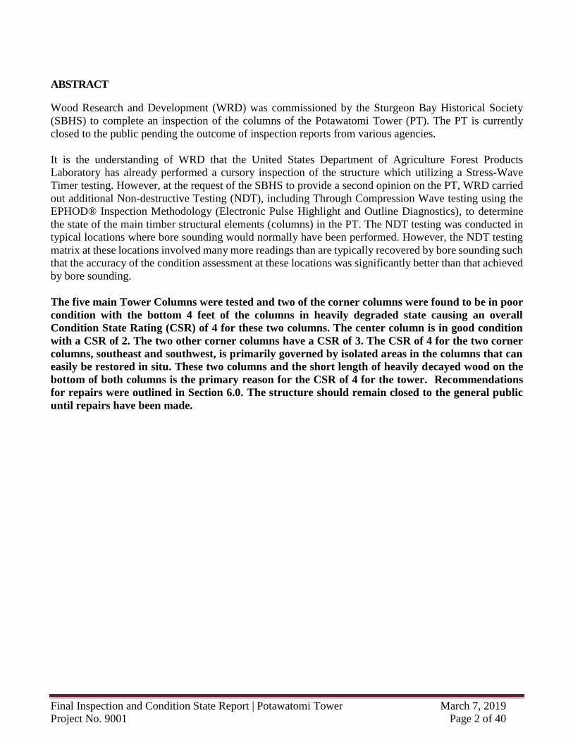
ABSTRACT
Wood Research and Development (WRD) was commissioned by the Sturgeon Bay Historical Society
(SBHS) to complete an inspection of the columns of the Potawatomi Tower (PT). The PT is currently
closed to the public pending the outcome of inspection reports from various agencies.
It is the understanding of WRD that the United States Department of Agriculture Forest Products
Laboratory has already performed a cursory inspection of the structure which utilizing a Stress-Wave
Timer testing. However, at the request of the SBHS to provide a second opinion on the PT, WRD carried
out additional Non-destructive Testing (NDT), including Through Compression Wave testing using the
EPHOD® Inspection Methodology (Electronic Pulse Highlight and Outline Diagnostics), to determine
the state of the main timber structural elements (columns) in the PT. The NDT testing was conducted in
typical locations where bore sounding would normally have been performed. However, the NDT testing
matrix at these locations involved many more readings than are typically recovered by bore sounding such
that the accuracy of the condition assessment at these locations was significantly better than that achieved
by bore sounding.
The five main Tower Columns were tested and two of the corner columns were found to be in poor
condition with the bottom 4 feet of the columns in heavily degraded state causing an overall
Condition State Rating (CSR) of 4 for these two columns. The center column is in good condition
with a CSR of 2. The two other corner columns have a CSR of 3. The CSR of 4 for the two corner
columns, southeast and southwest, is primarily governed by isolated areas in the columns that can
easily be restored in situ. These two columns and the short length of heavily decayed wood on the
bottom of both columns is the primary reason for the CSR of 4 for the tower. Recommendations
for repairs were outlined in Section 6.0. The structure should remain closed to the general public
until repairs have been made.
Final Inspection and Condition State Report | Potawatomi Tower March 7, 2019
Project No. 9001 Page 3 of 40
TABLE OF CONTENTS
ABSTRACT ............................................................................................................................................................................ 2
TABLE OF CONTENTS ........................................................................................................................................................... 3
1.0 INTRODUCTION .......................................................................................................................................................... 4
2.0 CURRENT CONDITION STATE RATING ......................................................................................................................... 5
3.0 FINDINGS – VISUAL INSPECTION ................................................................................................................................. 6
3.1 VISUAL INSPECTION – GENERAL............................................................................................................................................. 6 3.2 VISUAL INSPECTION – STAIRS, HANDRAILS AND PLATFORMS ....................................................................................................... 7 3.3 VISUAL INSPECTION – NORTHEAST TOWER LEG ........................................................................................................................ 8 3.4 VISUAL INSPECTION – SOUTHEAST TOWER LEG ........................................................................................................................ 9 3.5 VISUAL INSPECTION – SOUTHWEST TOWER LEG ..................................................................................................................... 10 3.6 VISUAL INSPECTION – NORTHWEST TOWER LEG ..................................................................................................................... 12 3.7 VISUAL INSPECTION – CENTER TOWER LEG ............................................................................................................................ 13
4.0 FINDINGS – STRESS WAVE TIME TESTING ................................................................................................................. 14
4.2 SWT SUMMARY - NORTHEAST TOWER LEG ........................................................................................................................... 15 4.3 SWT SUMMARY - SOUTHEAST TOWER LEG ........................................................................................................................... 16 4.4 SWT SUMMARY - SOUTHWEST TOWER LEG .......................................................................................................................... 17 4.5 SWT SUMMARY - NORTHWEST TOWER LEG .......................................................................................................................... 18 4.6 SWT SUMMARY - CENTER TOWER LEG ................................................................................................................................ 19 4.7 SWT SUMMARY - DRAWING .............................................................................................................................................. 20
5.0 CORE SAMPLE TEST RESULTS ......................................................................................................................................... 23
5.1 TIMBER CORES ................................................................................................................................................................. 23
6.0 RECOMMENDATIONS .................................................................................................................................................. 27
7.0 CONCLUSION ............................................................................................................................................................ 28
APPENDIX .......................................................................................................................................................................... 30
APPENDIX A – SWT SUMMARY DRAWINGS .................................................................................................................................... 31 APPENDIX B – SWT DATA ........................................................................................................................................................... 32
Final Inspection and Condition State Report | Potawatomi Tower March 7, 2019
Project No. 9001 Page 4 of 40
1.0 INTRODUCTION
An inspection of the Potawatomi Tower was completed by Wood Research and Development (WRD)
Level II Certified Inspection Technicians during the week of January 14th, 2019. The objective of the
investigation was to establish the general condition of the primary substructure elements. Visual
inspection and non-destructive testing were used in this investigation. An assortment of instruments were
utilized to complete the non-destructive tests, including; EPHOD™ Stress Wave Technology,
psychrometer, moisture meter, and digital camera. This final inspection report has been prepared by Dan
Tingley Ph.D., P.Eng. (Canada), MIEAust, CPEng, RPEQ, senior engineer and wood technologist for
WRD.
Potawatomi Tower (PT) is a 3-tiered structure standing approximately 75 feet tall located in Potawatomi
State Park near Sturgeon Bay, MI. The Tower is currently closed to the public. The structure is comprised
of four wood pole columns situated at the four corners of a square with a fifth column in the center. Each
column is positioned butt down resting on a concrete foundation with the 4 exterior columns angled toward
the interior of the structure. Several wood shim-like elements positioned at the base of each exterior
column help maintain the inward slant of the columns. They are positioned in between the column element
and the concrete foundation. The grain of these wood elements is parallel to the concrete footing with the
end grain facing outwards. Stairs wrap around the central wood pole column to provide access to three
observation levels. The first level is at approximately 25 feet, the second at 50 feet and the top level at 75
feet. The top observation level is open with handrails and used as a viewing platform. The tower is located
on top of Government Bluff a limestone quarry. It provides excellent views of Potawatomi State Park in
the State of Wisconsin.
The PT has a long history of service to the community. Its construction began with the tower design in
1929 at the beginning of the great depression and was completed in 1931with the help of the Sawyer
Commercial Club when they extended a $500 dollar grant for its construction. Money was hard to come
by in those days and the Tower represented a great way forward for the people in the community as it
provided a way to look out over the beauty of the land beyond all obstacles. To be free, to see, and to
dream. Much the same way as the people of the day gained strength to face the future by seeing how things
would be beyond the days of the great depression! The community and United States persevered, through
world wars, economic booms and busts, through it all the country grew. During all this time the tower also
persevered! It stood the test of time. When steel and concrete towers were falling down and being torn
down and taken out of service the Potawatomi Tower stood! When the experts said that timber towers
don’t last, only steel and concrete ones do, the timber Potawatoni Tower stood and still stands today!
This report contains the findings of WRD Level II Certified Timber Structures Inspection Technicians,
certified laboratory technicians and professional engineers who have worked on this project over a two
month period. The nomenclature used in this report is gathered from the USDA Forest Service. The
columns are labelled with their corresponding cardinal direction: Northwest, Northeast, Southwest,
Southeast, and Center. See the ‘Supplemental Documentation’ file for technical information on
deterioration, fungal decay, non-destructive testing, and methods of preventing decay. In addition, this
supplement document contains papers by Tingley on the difference between bore sounding, global
stiffness inspection methods and an elemental strength NDT equipment system like the EPHOD™ system
used in this inspection, amongst other topics.
Section 6.0 of this report outlines the proposed repair strategies for elements which require remediation.
Final Inspection and Condition State Report | Potawatomi Tower March 7, 2019
Project No. 9001 Page 5 of 40
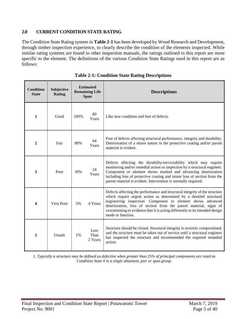
2.0 CURRENT CONDITION STATE RATING
The Condition State Rating system in Table 2-1 has been developed by Wood Research and Development,
through timber inspection experience, to clearly describe the condition of the elements inspected. While
similar rating systems are found in other inspection manuals, the ratings outlined in this report are more
specific to the element. The definitions of the various Condition State Ratings used in this report are as
follows:
Table 2-1: Condition State Rating Descriptions
Condition
State
Subjective
Rating
Estimated
Remaining Life
Span Descriptions
1 Good 100% 80
Years Like new condition and free of defects.
2 Fair 80% 64
Years
Free of defects affecting structural performance, integrity and durability.
Deterioration of a minor nature in the protective coating and/or parent
material is evident.
3 Poor 30% 24
Years
Defects affecting the durability/serviceability which may require
monitoring and/or remedial action or inspection by a structural engineer.
Component or element shows marked and advancing deterioration
including loss of protective coating and minor loss of section from the
parent material is evident. Intervention is normally required.
4 Very Poor 5% 4 Years
Defects affecting the performance and structural integrity of the structure
which require urgent action as determined by a detailed structural
engineering inspection. Component or element shows advanced
deterioration, loss of section from the parent material, signs of
overstressing or evidence that it is acting differently to its intended design
mode or function.
5 Unsafe 1%
Less
Than
2 Years
Structure should be closed. Structural integrity is severely compromised,
and the structure must be taken out of service until a structural engineer
has inspected the structure and recommended the required remedial
action.
1. Typically a structure may be defined as defective when greater than 25% of principal components are rated as
Condition State 4 in a single abutment, pier or span group.
Final Inspection and Condition State Report | Potawatomi Tower March 7, 2019
Project No. 9001 Page 6 of 40
3.0 FINDINGS – VISUAL INSPECTION
A visual inspection of a timber structure is an essential step in evaluating its condition. The visual data
gathered from the inspection is used to determine structural defects that the non-destructive testing will
not, such as missing or failed elements, cracks and splits, cavities, connection details as well as other vital
information. Gathering this information is critical for completing an inclusive and comprehensive
investigation, which takes into account the surroundings in addition to the main structural elements
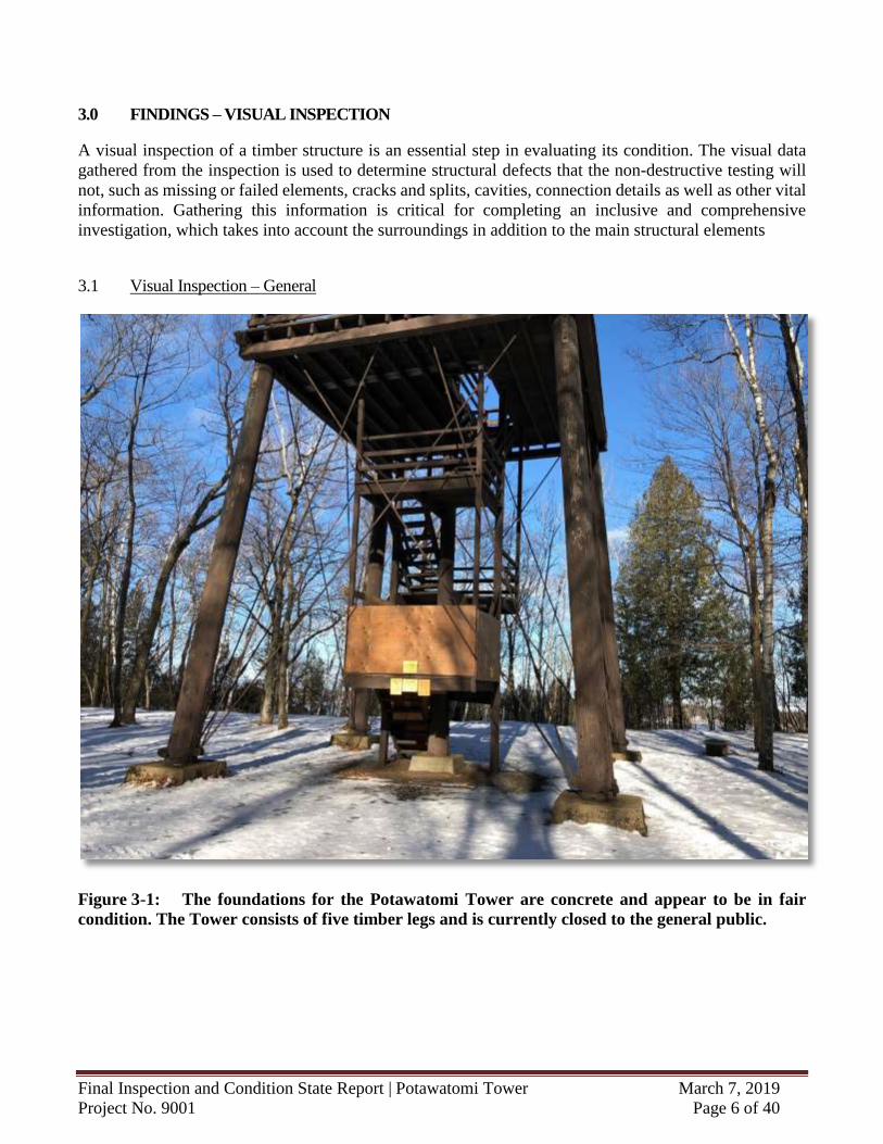
3.1 Visual Inspection – General
Figure 3-1: The foundations for the Potawatomi Tower are concrete and appear to be in fair
condition. The Tower consists of five timber legs and is currently closed to the general public.
Final Inspection and Condition State Report | Potawatomi Tower March 7, 2019
Project No. 9001 Page 7 of 40
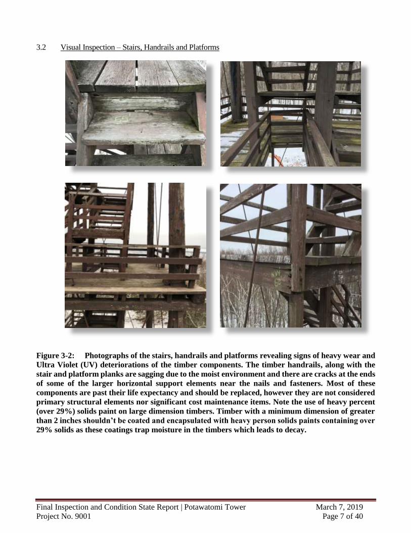
3.2 Visual Inspection – Stairs, Handrails and Platforms
Figure 3-2: Photographs of the stairs, handrails and platforms revealing signs of heavy wear and
Ultra Violet (UV) deteriorations of the timber components. The timber handrails, along with the
stair and platform planks are sagging due to the moist environment and there are cracks at the ends
of some of the larger horizontal support elements near the nails and fasteners. Most of these
components are past their life expectancy and should be replaced, however they are not considered
primary structural elements nor significant cost maintenance items. Note the use of heavy percent
(over 29%) solids paint on large dimension timbers. Timber with a minimum dimension of greater
than 2 inches shouldn’t be coated and encapsulated with heavy person solids paints containing over
29% solids as these coatings trap moisture in the timbers which leads to decay.
Final Inspection and Condition State Report | Potawatomi Tower March 7, 2019
Project No. 9001 Page 8 of 40
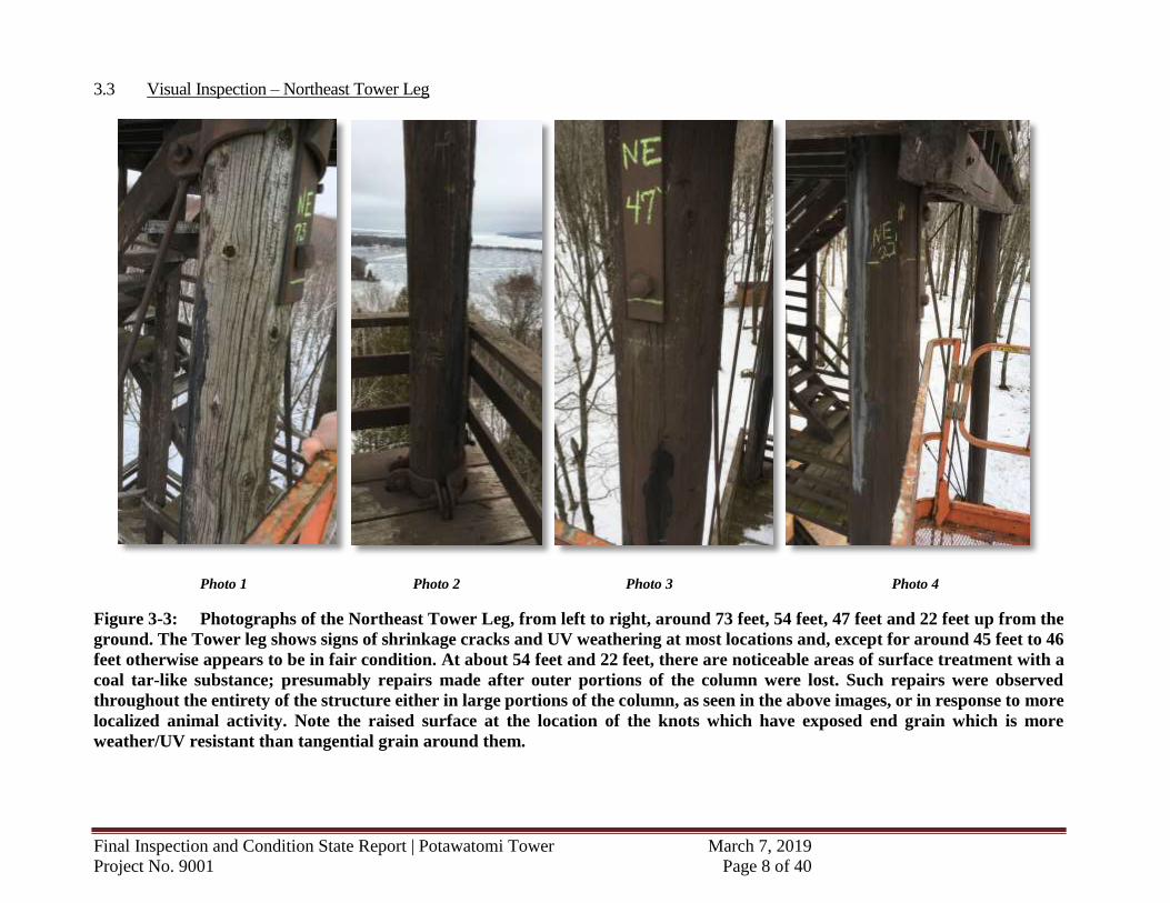
3.3 Visual Inspection – Northeast Tower Leg
Photo 1 Photo 2 Photo 3 Photo 4
Figure 3-3: Photographs of the Northeast Tower Leg, from left to right, around 73 feet, 54 feet, 47 feet and 22 feet up from the
ground. The Tower leg shows signs of shrinkage cracks and UV weathering at most locations and, except for around 45 feet to 46
feet otherwise appears to be in fair condition. At about 54 feet and 22 feet, there are noticeable areas of surface treatment with a
coal tar-like substance; presumably repairs made after outer portions of the column were lost. Such repairs were observed
throughout the entirety of the structure either in large portions of the column, as seen in the above images, or in response to more
localized animal activity. Note the raised surface at the location of the knots which have exposed end grain which is more
weather/UV resistant than tangential grain around them.
Final Inspection and Condition State Report | Potawatomi Tower March 7, 2019
Project No. 9001 Page 9 of 40
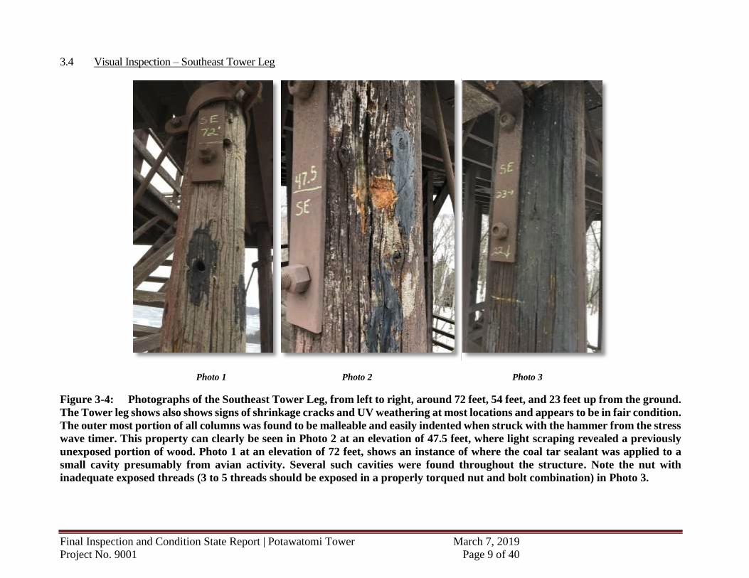
3.4 Visual Inspection – Southeast Tower Leg
Photo 1 Photo 2 Photo 3
Figure 3-4: Photographs of the Southeast Tower Leg, from left to right, around 72 feet, 54 feet, and 23 feet up from the ground.
The Tower leg shows also shows signs of shrinkage cracks and UV weathering at most locations and appears to be in fair condition.
The outer most portion of all columns was found to be malleable and easily indented when struck with the hammer from the stress
wave timer. This property can clearly be seen in Photo 2 at an elevation of 47.5 feet, where light scraping revealed a previously
unexposed portion of wood. Photo 1 at an elevation of 72 feet, shows an instance of where the coal tar sealant was applied to a
small cavity presumably from avian activity. Several such cavities were found throughout the structure. Note the nut with
inadequate exposed threads (3 to 5 threads should be exposed in a properly torqued nut and bolt combination) in Photo 3.
Final Inspection and Condition State Report | Potawatomi Tower March 7, 2019
Project No. 9001 Page 10 of 40
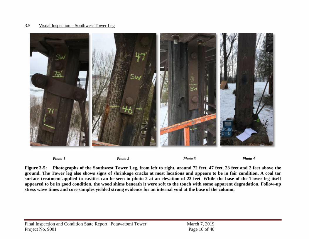
3.5 Visual Inspection – Southwest Tower Leg
Photo 1 Photo 2 Photo 3 Photo 4
Figure 3-5: Photographs of the Southwest Tower Leg, from left to right, around 72 feet, 47 feet, 23 feet and 2 feet above the
ground. The Tower leg also shows signs of shrinkage cracks at most locations and appears to be in fair condition. A coal tar
surface treatment applied to cavities can be seen in photo 2 at an elevation of 23 feet. While the base of the Tower leg itself
appeared to be in good condition, the wood shims beneath it were soft to the touch with some apparent degradation. Follow-up
stress wave times and core samples yielded strong evidence for an internal void at the base of the column.
Final Inspection and Condition State Report | Potawatomi Tower March 7, 2019
Project No. 9001 Page 11 of 40
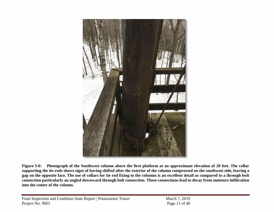
Figure 3-6: Photograph of the Southwest column above the first platform at an approximate elevation of 28 feet. The collar
supporting the tie-rods shows signs of having shifted after the exterior of the column compressed on the southwest side, leaving a
gap on the opposite face. The use of collars for tie rod fixing to the columns is an excellent detail as compared to a through bolt
connection particularly an angled downward through bolt connection. These connections lead to decay from moisture infiltration
into the center of the column.
Final Inspection and Condition State Report | Potawatomi Tower March 7, 2019
Project No. 9001 Page 12 of 40
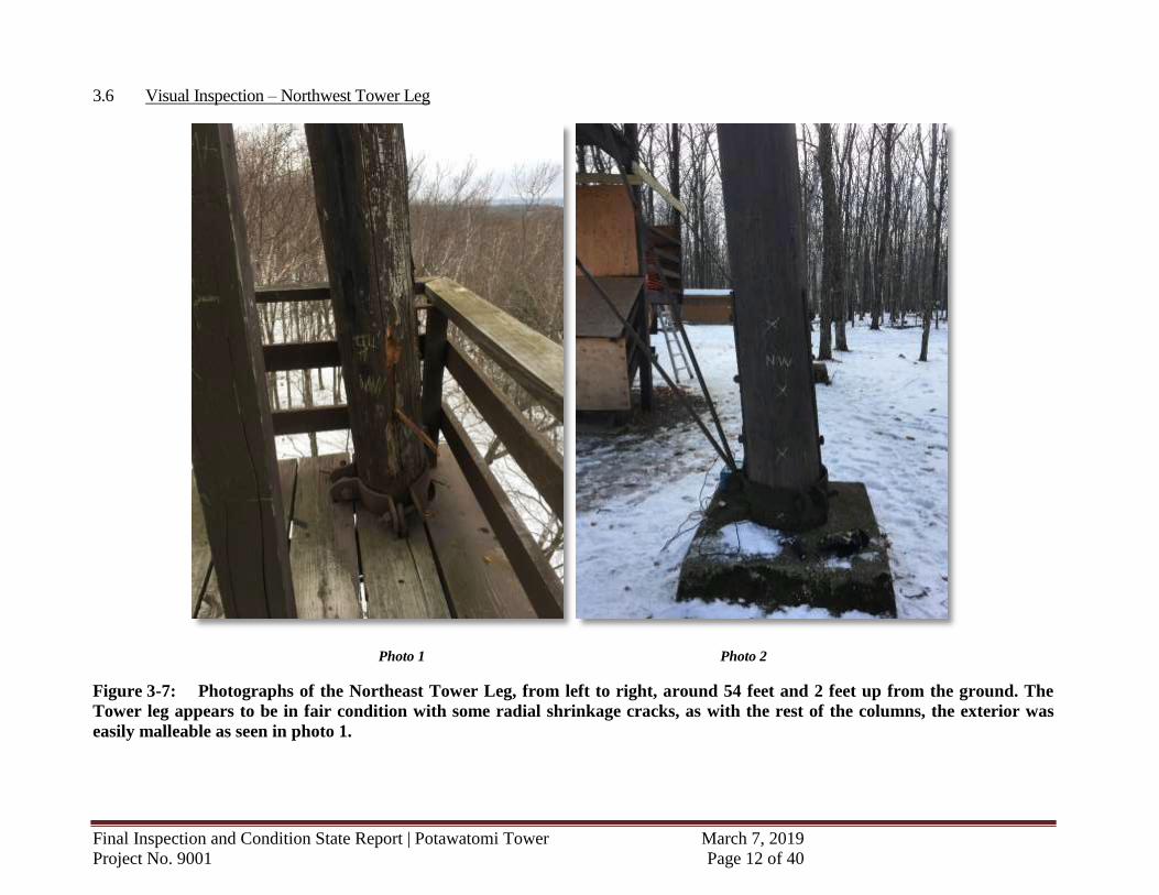
3.6 Visual Inspection – Northwest Tower Leg
Photo 1 Photo 2
Figure 3-7: Photographs of the Northeast Tower Leg, from left to right, around 54 feet and 2 feet up from the ground. The
Tower leg appears to be in fair condition with some radial shrinkage cracks, as with the rest of the columns, the exterior was
easily malleable as seen in photo 1.
Final Inspection and Condition State Report | Potawatomi Tower March 7, 2019
Project No. 9001 Page 13 of 40
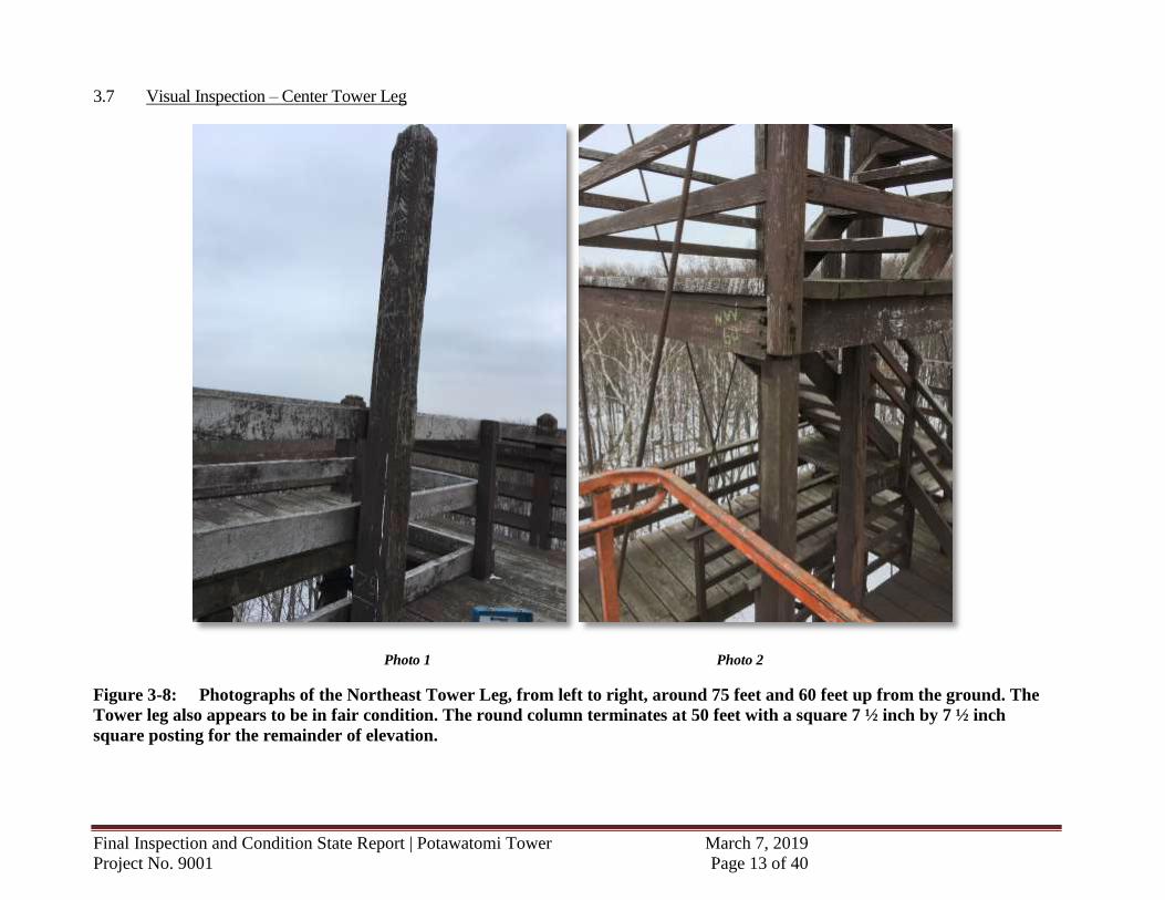
3.7 Visual Inspection – Center Tower Leg
Photo 1 Photo 2
Figure 3-8: Photographs of the Northeast Tower Leg, from left to right, around 75 feet and 60 feet up from the ground. The
Tower leg also appears to be in fair condition. The round column terminates at 50 feet with a square 7 ½ inch by 7 ½ inch
square posting for the remainder of elevation.
Final Inspection and Condition State Report | Potawatomi Tower March 7, 2019
Project No. 9001 Page 14 of 40
4.0 FINDINGS – STRESS WAVE TIME TESTING - EPHOD® SYSTEM
This inspection included the use of non-destructive test equipment identified as EPHOD™ (Electronic
Pulse Highlight and Outline Diagnostic) through compression wave technology. The EPHOD™
Equipment was utilized to complete the through compression stress wave measurements along with other
WRD techniques to locate internal decay in a non-destructive nature.
Stress wave time readings were recorded on all of the accessible main timber structural elements.
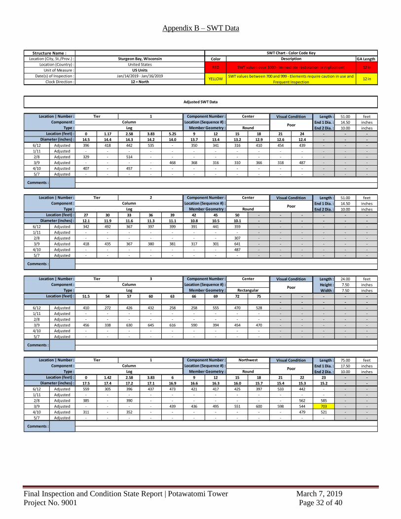
Appendix B shows the stress wave time readings for all of the elements tested. When the stress wave time
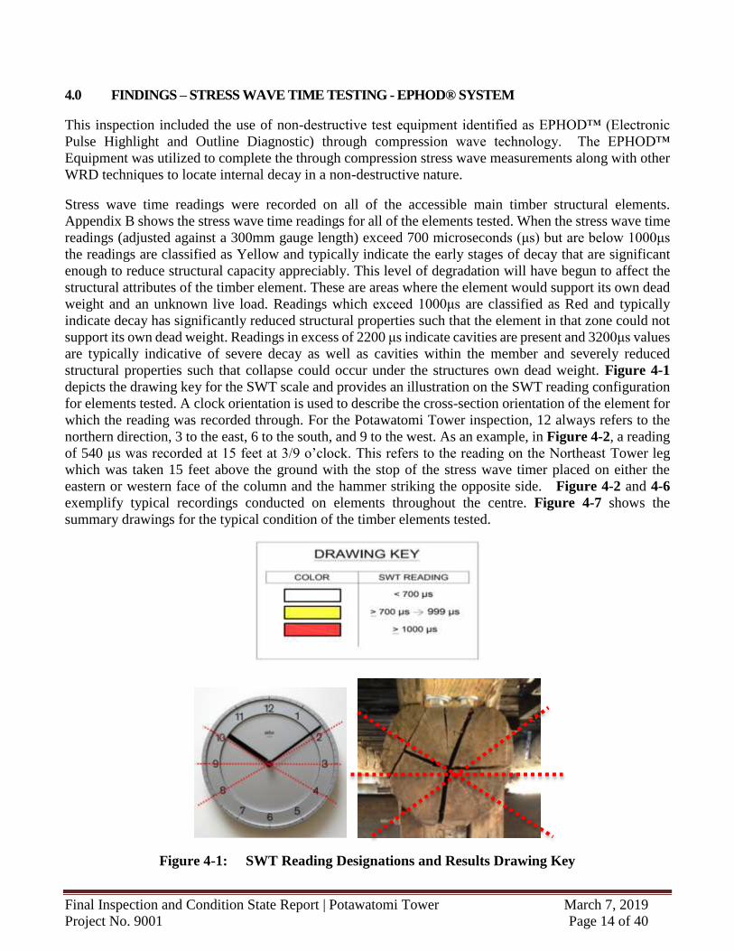
readings (adjusted against a 300mm gauge length) exceed 700 microseconds (μs) but are below 1000μs
the readings are classified as Yellow and typically indicate the early stages of decay that are significant
enough to reduce structural capacity appreciably. This level of degradation will have begun to affect the
structural attributes of the timber element. These are areas where the element would support its own dead
weight and an unknown live load. Readings which exceed 1000μs are classified as Red and typically
indicate decay has significantly reduced structural properties such that the element in that zone could not
support its own dead weight. Readings in excess of 2200 μs indicate cavities are present and 3200μs values
are typically indicative of severe decay as well as cavities within the member and severely reduced
structural properties such that collapse could occur under the structures own dead weight. Figure 4-1
depicts the drawing key for the SWT scale and provides an illustration on the SWT reading configuration
for elements tested. A clock orientation is used to describe the cross-section orientation of the element for
which the reading was recorded through. For the Potawatomi Tower inspection, 12 always refers to the
northern direction, 3 to the east, 6 to the south, and 9 to the west. As an example, in Figure 4-2, a reading
of 540 μs was recorded at 15 feet at 3/9 o’clock. This refers to the reading on the Northeast Tower leg
which was taken 15 feet above the ground with the stop of the stress wave timer placed on either the
eastern or western face of the column and the hammer striking the opposite side. Figure 4-2 and 4-6
exemplify typical recordings conducted on elements throughout the centre. Figure 4-7 shows the
summary drawings for the typical condition of the timber elements tested.
Figure 4-1: SWT Reading Designations and Results Drawing Key
Final Inspection and Condition State Report | Potawatomi Tower March 7, 2019
Project No. 9001 Page 15 of 40
4.2 SWT Summary - Northeast Tower Leg
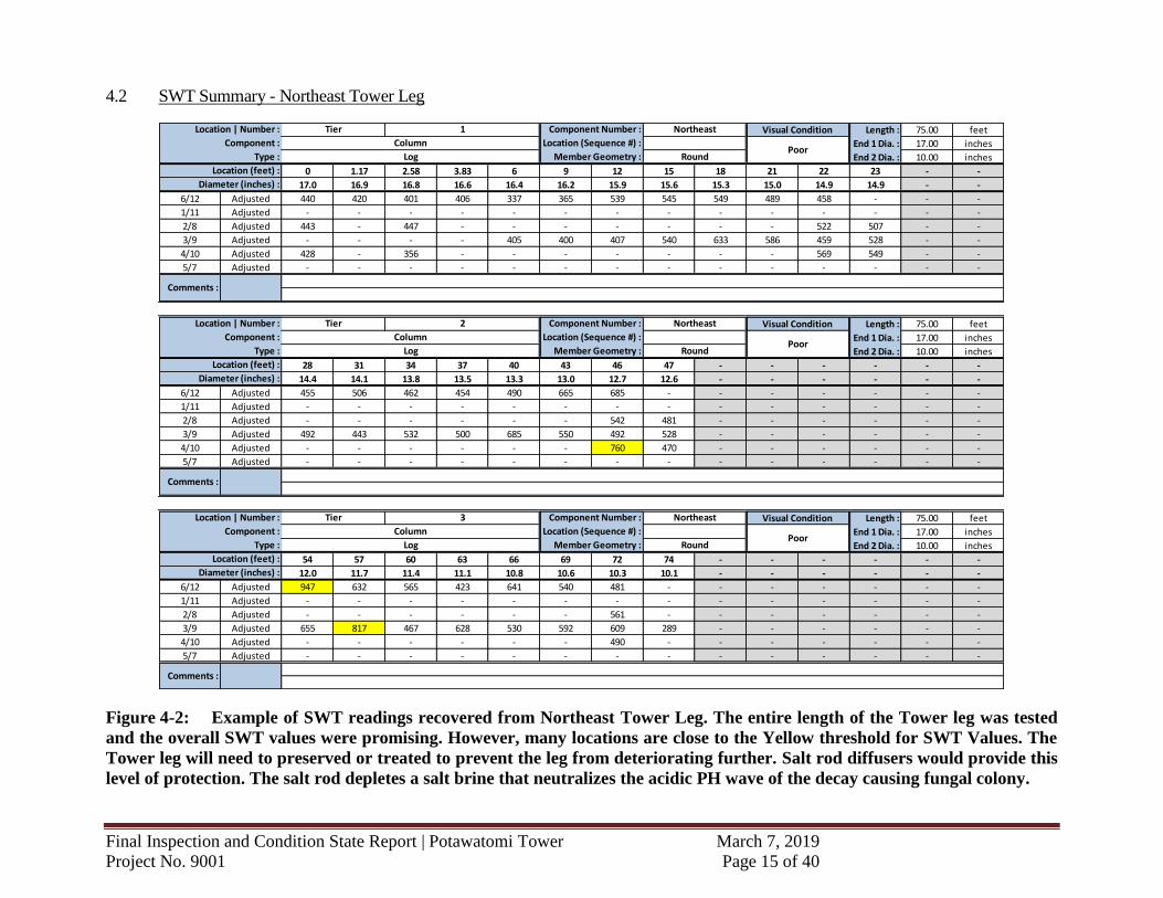
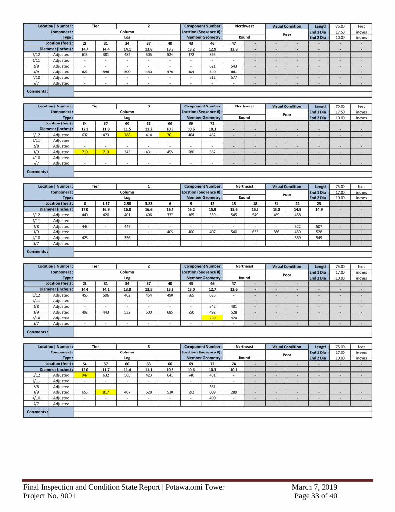
Figure 4-2: Example of SWT readings recovered from Northeast Tower Leg. The entire length of the Tower leg was tested
and the overall SWT values were promising. However, many locations are close to the Yellow threshold for SWT Values. The
Tower leg will need to preserved or treated to prevent the leg from deteriorating further. Salt rod diffusers would provide this
level of protection. The salt rod depletes a salt brine that neutralizes the acidic PH wave of the decay causing fungal colony.
Length : 75.00 feet
End 1 Dia. : 17.00 inches
End 2 Dia. : 10.00 inches
0 1.17 2.58 3.83 6 9 12 15 18 21 22 23 - -
17.0 16.9 16.8 16.6 16.4 16.2 15.9 15.6 15.3 15.0 14.9 14.9 - -
6/12 Adjusted 440 420 401 406 337 365 539 545 549 489 458 - - -
1/11 Adjusted - - - - - - - - - - - - - -
2/8 Adjusted 443 - 447 - - - - - - - 522 507 - -
3/9 Adjusted - - - - 405 400 407 540 633 586 459 528 - -
4/10 Adjusted 428 - 356 - - - - - - - 569 549 - -
5/7 Adjusted - - - - - - - - - - - - - -
Length : 75.00 feet
End 1 Dia. : 17.00 inches
End 2 Dia. : 10.00 inches
28 31 34 37 40 43 46 47 - - - - - -
14.4 14.1 13.8 13.5 13.3 13.0 12.7 12.6 - - - - - -
6/12 Adjusted 455 506 462 454 490 665 685 - - - - - - -
1/11 Adjusted - - - - - - - - - - - - - -
2/8 Adjusted - - - - - - 542 481 - - - - - -
3/9 Adjusted 492 443 532 500 685 550 492 528 - - - - - -
4/10 Adjusted - - - - - - 760 470 - - - - - -
5/7 Adjusted - - - - - - - - - - - - - -
Length : 75.00 feet
End 1 Dia. : 17.00 inches
End 2 Dia. : 10.00 inches
54 57 60 63 66 69 72 74 - - - - - -
12.0 11.7 11.4 11.1 10.8 10.6 10.3 10.1 - - - - - -
6/12 Adjusted 947 632 565 423 641 540 481 - - - - - - -
1/11 Adjusted - - - - - - - - - - - - - -
2/8 Adjusted - - - - - - 561 - - - - - - -
3/9 Adjusted 655 817 467 628 530 592 609 289 - - - - - -
4/10 Adjusted - - - - - - 490 - - - - - - -
5/7 Adjusted - - - - - - - - - - - - - -
Comments :
Log Member Geometry : Round
Location (feet) :
Diameter (inches) :
Location | Number : Tier 2 Component Number : Northeast Visual Condition
Component : Column Location (Sequence #) :Poor
Type :
Location (feet) :
Diameter (inches) :
Comments :
Component : Column Location (Sequence #) :Poor
Type : Log Member Geometry : Round
Location | Number : Tier 3 Component Number : Northeast Visual Condition
Location (feet) :
Diameter (inches) :
Comments :
Component : Column Location (Sequence #) :Poor
Type : Log Member Geometry : Round
Location | Number : Tier 1 Component Number : Northeast Visual Condition
Final Inspection and Condition State Report | Potawatomi Tower March 7, 2019
Project No. 9001 Page 16 of 40
4.3 SWT Summary - Southeast Tower Leg
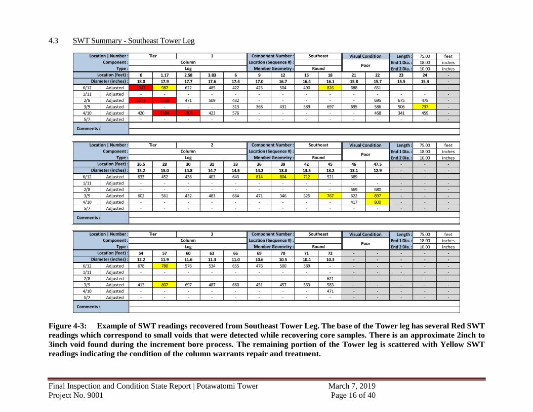
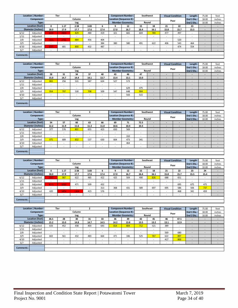
Figure 4-3: Example of SWT readings recovered from Southeast Tower Leg. The base of the Tower leg has several Red SWT
readings which correspond to small voids that were detected while recovering core samples. There is an approximate 2inch to
3inch void found during the increment bore process. The remaining portion of the Tower leg is scattered with Yellow SWT
readings indicating the condition of the column warrants repair and treatment.
Length : 75.00 feet
End 1 Dia. : 18.00 inches
End 2 Dia. : 10.00 inches
0 1.17 2.58 3.83 6 9 12 15 18 21 22 23 24 -
18.0 17.9 17.7 17.6 17.4 17.0 16.7 16.4 16.1 15.8 15.7 15.5 15.4 -
6/12 Adjusted 1347 987 622 485 422 425 504 490 826 688 651 - - -
1/11 Adjusted - - - - - - - - - - - - - -
2/8 Adjusted 1071 1223 471 509 432 - - - - - 695 675 475 -
3/9 Adjusted - - - - 313 368 431 589 697 695 586 506 737 -
4/10 Adjusted 420 1494 1304 423 576 - - - - - 468 341 459 -
5/7 Adjusted - - - - - - - - - - - - - -
Length : 75.00 feet
End 1 Dia. : 18.00 inches
End 2 Dia. : 10.00 inches
26.5 28 30 31 33 36 39 42 45 46 47.5 - - -
15.2 15.0 14.8 14.7 14.5 14.2 13.8 13.5 13.2 13.1 12.9 - - -
6/12 Adjusted 633 452 438 403 643 814 804 712 521 389 - - - -
1/11 Adjusted - - - - - - - - - - - - - -
2/8 Adjusted - - - - - - - - - 569 680 - - -
3/9 Adjusted 602 561 432 483 664 471 346 525 767 622 897 - - -
4/10 Adjusted - - - - - - - - - 417 800 - - -
5/7 Adjusted - - - - - - - - - - - - - -
Length : 75.00 feet
End 1 Dia. : 18.00 inches
End 2 Dia. : 10.00 inches
54 57 60 63 66 69 70 71 72 - - - - -
12.2 11.9 11.6 11.3 11.0 10.6 10.5 10.4 10.3 - - - - -
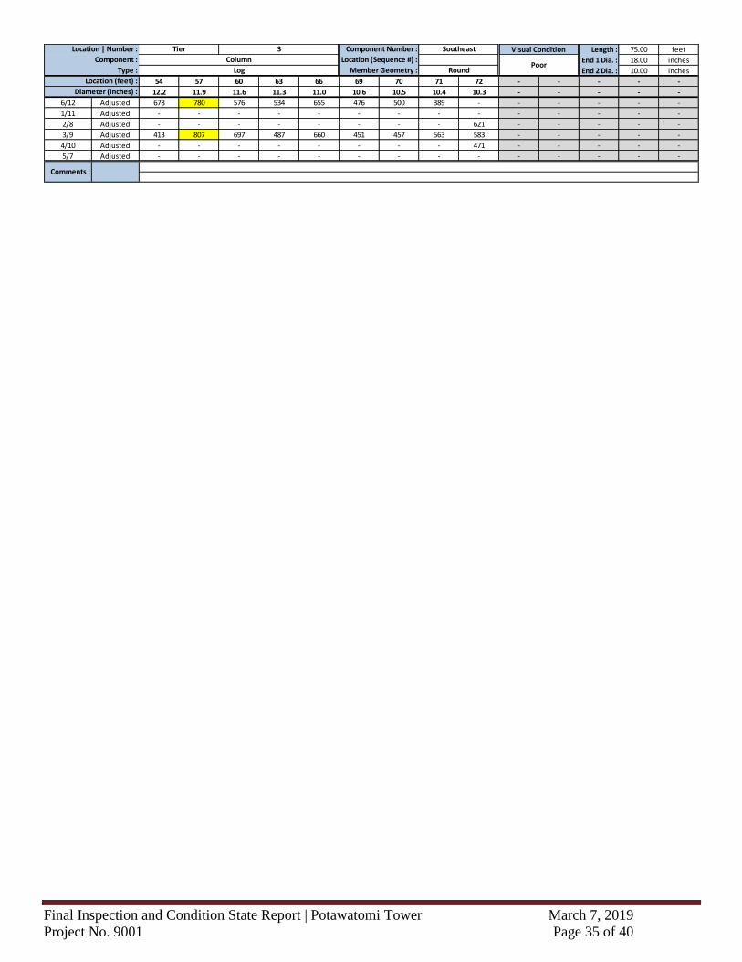
6/12 Adjusted 678 780 576 534 655 476 500 389 - - - - - -
1/11 Adjusted - - - - - - - - - - - - - -
2/8 Adjusted - - - - - - - - 621 - - - - -
3/9 Adjusted 413 807 697 487 660 451 457 563 583 - - - - -
4/10 Adjusted - - - - - - - - 471 - - - - -
5/7 Adjusted - - - - - - - - - - - - - -
Location | Number : Tier 1 Component Number : Southeast Visual Condition
Component : Column Location (Sequence #) :Poor
Type : Log Member Geometry : Round
Location (feet) :
Diameter (inches) :
Comments :
Location | Number : Tier 2 Component Number : Southeast Visual Condition
Component : Column Location (Sequence #) :Poor
Type : Log Member Geometry : Round
Location (feet) :
Diameter (inches) :
Comments :
Location | Number : Tier 3 Component Number : Southeast Visual Condition
Component : Column Location (Sequence #) :Poor
Type : Log Member Geometry : Round
Location (feet) :
Diameter (inches) :
Comments :
Final Inspection and Condition State Report | Potawatomi Tower March 7, 2019
Project No. 9001 Page 17 of 40
4.4 SWT Summary - Southwest Tower Leg
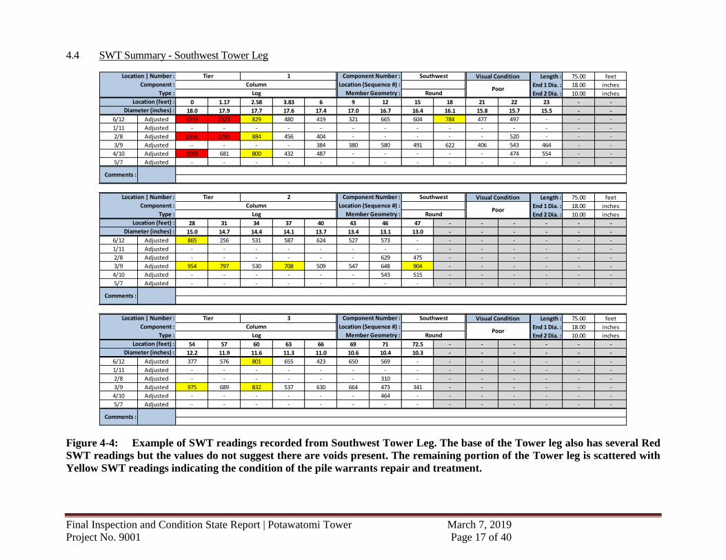
Figure 4-4: Example of SWT readings recorded from Southwest Tower Leg. The base of the Tower leg also has several Red
SWT readings but the values do not suggest there are voids present. The remaining portion of the Tower leg is scattered with
Yellow SWT readings indicating the condition of the pile warrants repair and treatment.
Length : 75.00 feet
End 1 Dia. : 18.00 inches
End 2 Dia. : 10.00 inches
0 1.17 2.58 3.83 6 9 12 15 18 21 22 23 - -
18.0 17.9 17.7 17.6 17.4 17.0 16.7 16.4 16.1 15.8 15.7 15.5 - -
6/12 Adjusted 1539 2323 829 480 419 321 665 604 784 477 497 - - -
1/11 Adjusted - - - - - - - - - - - - - -
2/8 Adjusted 2366 2791 884 456 404 - - - - - 520 - - -
3/9 Adjusted - - - - 384 380 580 491 622 406 543 464 - -
4/10 Adjusted 1089 681 800 432 487 - - - - - 474 554 - -
5/7 Adjusted - - - - - - - - - - - - - -
Length : 75.00 feet
End 1 Dia. : 18.00 inches
End 2 Dia. : 10.00 inches
28 31 34 37 40 43 46 47 - - - - - -
15.0 14.7 14.4 14.1 13.7 13.4 13.1 13.0 - - - - - -
6/12 Adjusted 865 256 531 587 624 527 573 - - - - - - -
1/11 Adjusted - - - - - - - - - - - - - -
2/8 Adjusted - - - - - - 629 475 - - - - - -
3/9 Adjusted 954 797 530 708 509 547 648 904 - - - - - -
4/10 Adjusted - - - - - - 543 515 - - - - - -
5/7 Adjusted - - - - - - - - - - - - - -
Length : 75.00 feet
End 1 Dia. : 18.00 inches
End 2 Dia. : 10.00 inches
54 57 60 63 66 69 71 72.5 - - - - - -
12.2 11.9 11.6 11.3 11.0 10.6 10.4 10.3 - - - - - -
6/12 Adjusted 377 576 801 655 423 650 569 - - - - - - -
1/11 Adjusted - - - - - - - - - - - - - -
2/8 Adjusted - - - - - - 310 - - - - - - -
3/9 Adjusted 975 689 832 537 630 664 473 341 - - - - - -
4/10 Adjusted - - - - - - 464 - - - - - - -
5/7 Adjusted - - - - - - - - - - - - - -
Location | Number : Tier 1 Component Number : Southwest Visual Condition
Component : Column Location (Sequence #) :Poor
Type : Log Member Geometry : Round
Location (feet) :
Diameter (inches) :
Comments :
Location | Number : Tier 3 Component Number : Southwest Visual Condition
Component : Column Location (Sequence #) :Poor
Type : Log Member Geometry : Round
Location (feet) :
Diameter (inches) :
Comments :
Location | Number : Tier 2 Component Number : Southwest Visual Condition
Component : Column Location (Sequence #) :Poor
Type : Log Member Geometry : Round
Location (feet) :
Diameter (inches) :
Comments :
Final Inspection and Condition State Report | Potawatomi Tower March 7, 2019
Project No. 9001 Page 18 of 40
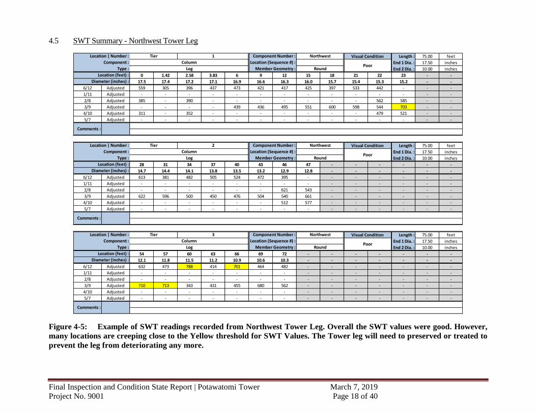
4.5 SWT Summary - Northwest Tower Leg
Figure 4-5: Example of SWT readings recorded from Northwest Tower Leg. Overall the SWT values were good. However,
many locations are creeping close to the Yellow threshold for SWT Values. The Tower leg will need to preserved or treated to
prevent the leg from deteriorating any more.
Length : 75.00 feet
End 1 Dia. : 17.50 inches
End 2 Dia. : 10.00 inches
0 1.42 2.58 3.83 6 9 12 15 18 21 22 23 - -
17.5 17.4 17.2 17.1 16.9 16.6 16.3 16.0 15.7 15.4 15.3 15.2 - -
6/12 Adjusted 559 305 396 437 473 421 417 425 397 533 442 - - -
1/11 Adjusted - - - - - - - - - - - - - -
2/8 Adjusted 385 - 390 - - - - - - - 562 585 - -
3/9 Adjusted - - - - 439 436 495 551 600 598 544 703 - -
4/10 Adjusted 311 - 352 - - - - - - - 479 521 - -
5/7 Adjusted - - - - - - - - - - - - - -
Length : 75.00 feet
End 1 Dia. : 17.50 inches
End 2 Dia. : 10.00 inches
28 31 34 37 40 43 46 47 - - - - - -
14.7 14.4 14.1 13.8 13.5 13.2 12.9 12.8 - - - - - -
6/12 Adjusted 613 381 482 505 524 472 395 - - - - - - -
1/11 Adjusted - - - - - - - - - - - - - -
2/8 Adjusted - - - - - - 621 543 - - - - - -
3/9 Adjusted 622 596 500 450 476 504 540 661 - - - - - -
4/10 Adjusted - - - - - - 512 577 - - - - - -
5/7 Adjusted - - - - - - - - - - - - - -
Length : 75.00 feet
End 1 Dia. : 17.50 inches
End 2 Dia. : 10.00 inches
54 57 60 63 66 69 72 - - - - - - -
12.1 11.8 11.5 11.2 10.9 10.6 10.3 - - - - - - -
6/12 Adjusted 632 473 788 414 701 464 482 - - - - - - -
1/11 Adjusted - - - - - - - - - - - - - -
2/8 Adjusted - - - - - - - - - - - - - -
3/9 Adjusted 710 713 343 431 455 680 562 - - - - - - -
4/10 Adjusted - - - - - - - - - - - - - -
5/7 Adjusted - - - - - - - - - - - - - -
Location | Number : Tier 1 Component Number : Northwest Visual Condition
Component : Column Location (Sequence #) :Poor
Type : Log Member Geometry : Round
Location (feet) :
Diameter (inches) :
Comments :
Location | Number : Tier 3 Component Number : Northwest Visual Condition
Component : Column Location (Sequence #) :Poor
Type : Log Member Geometry : Round
Location (feet) :
Diameter (inches) :
Comments :
Location | Number : Tier 2 Component Number : Northwest Visual Condition
Component : Column Location (Sequence #) :Poor
Type : Log Member Geometry : Round
Location (feet) :
Diameter (inches) :
Comments :

Final Inspection and Condition State Report | Potawatomi Tower March 7, 2019
Project No. 9001 Page 19 of 40
4.6 SWT Summary - Center Tower Leg
Figure 4-6: Example of SWT readings recorded from the Center Tower Leg. Overall the Tower leg is fair to good condition.
Length : 51.00 feet
End 1 Dia. : 14.50 inches
End 2 Dia. : 10.00 inches
0 1.17 2.58 3.83 5.25 9 12 15 18 21 24 - - -
14.5 14.4 14.3 14.2 14.0 13.7 13.4 13.2 12.9 12.6 12.4 - - -
6/12 Adjusted 396 418 442 535 - 350 341 316 410 454 439 - - -
1/11 Adjusted - - - - - - - - - - - - - -
2/8 Adjusted 329 - 514 - - - - - - - - - - -
3/9 Adjusted - - - - 468 368 316 310 366 318 487 - - -
4/10 Adjusted 407 - 457 - - - - - - - - - - -
5/7 Adjusted - - - - - - - - - - - - - -
Length : 51.00 feet
End 1 Dia. : 14.50 inches
End 2 Dia. : 10.00 inches
27 30 33 36 39 42 45 50 - - - - - -
12.1 11.9 11.6 11.3 11.1 10.8 10.5 10.1 - - - - - -
6/12 Adjusted 342 492 367 397 399 391 441 359 - - - - - -
1/11 Adjusted - - - - - - - - - - - - - -
2/8 Adjusted - - - - - - - 307 - - - - - -
3/9 Adjusted 418 435 367 380 381 317 301 641 - - - - - -
4/10 Adjusted - - - - - - - 487 - - - - - -
5/7 Adjusted - - - - - - - - - - - - - -
Length : 24.00 feet
Height : 7.50 inches
Width : 7.50 inches
51.5 54 57 60 63 66 69 72 75 - - - - -
- - - - -
6/12 Adjusted 410 272 426 432 258 258 555 470 528 - - - - -
1/11 Adjusted - - - - - - - - - - - - - -
2/8 Adjusted - - - - - - - - - - - - - -
3/9 Adjusted 456 338 630 645 616 590 394 454 470 - - - - -
4/10 Adjusted - - - - - - - - - - - - - -
5/7 Adjusted - - - - - - - - - - - - - -
1
Comments :
Tier Component Number : Center Visual Condition
Column Location (Sequence #) :
RoundLog Member Geometry :Poor
Location | Number :
Component :
Location | Number : Tier 2 Component Number :
Type :
Location (feet) :
Diameter (inches) :
Center Visual Condition
Component : Column Location (Sequence #) :Poor
Type : Log Member Geometry : Round
Location (feet) :
Diameter (inches) :
Comments :
Location | Number : Tier 3 Component Number : Center Visual Condition
Component : Column Location (Sequence #) :Poor
Type : Log Member Geometry : Rectangular
Location (feet) :
Comments :
Final Inspection and Condition State Report | Potawatomi Tower March 7, 2019
Project No. 9001 Page 20 of 40
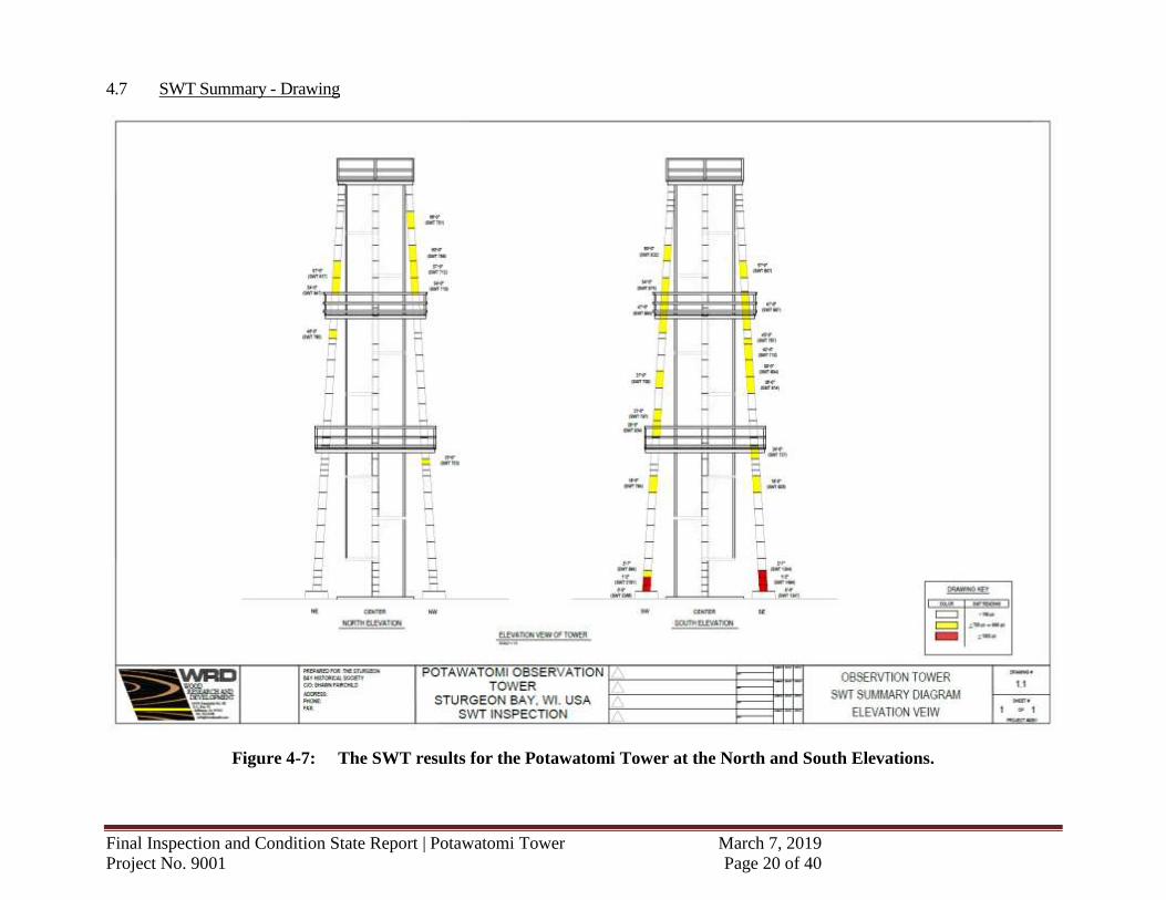
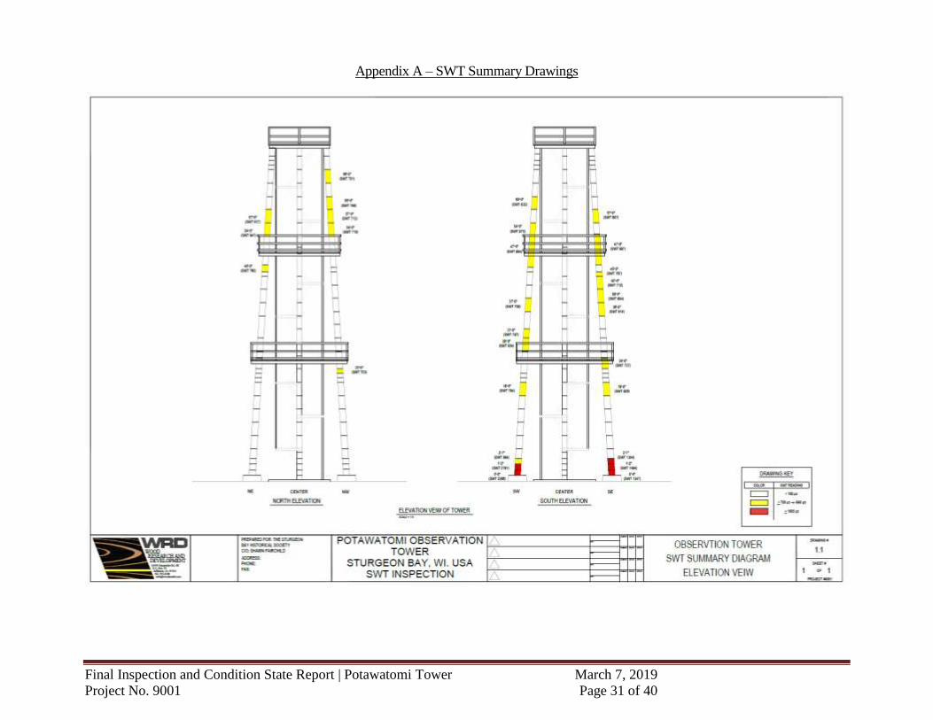
4.7 SWT Summary - Drawing
Figure 4-7: The SWT results for the Potawatomi Tower at the North and South Elevations.
Final Inspection and Condition State Report | Potawatomi Tower March 7, 2019
Project No. 9001 Page 21 of 40
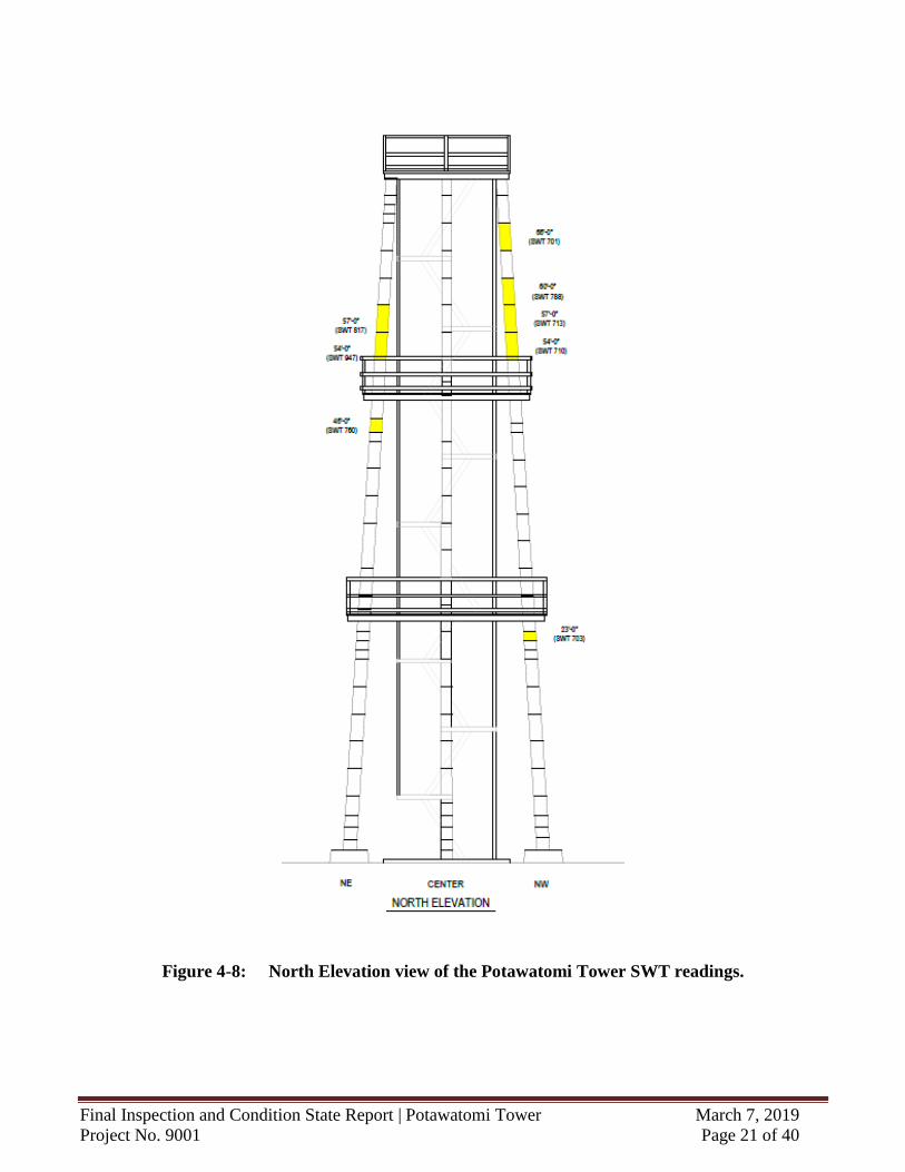
Figure 4-8: North Elevation view of the Potawatomi Tower SWT readings.
Final Inspection and Condition State Report | Potawatomi Tower March 7, 2019
Project No. 9001 Page 22 of 40
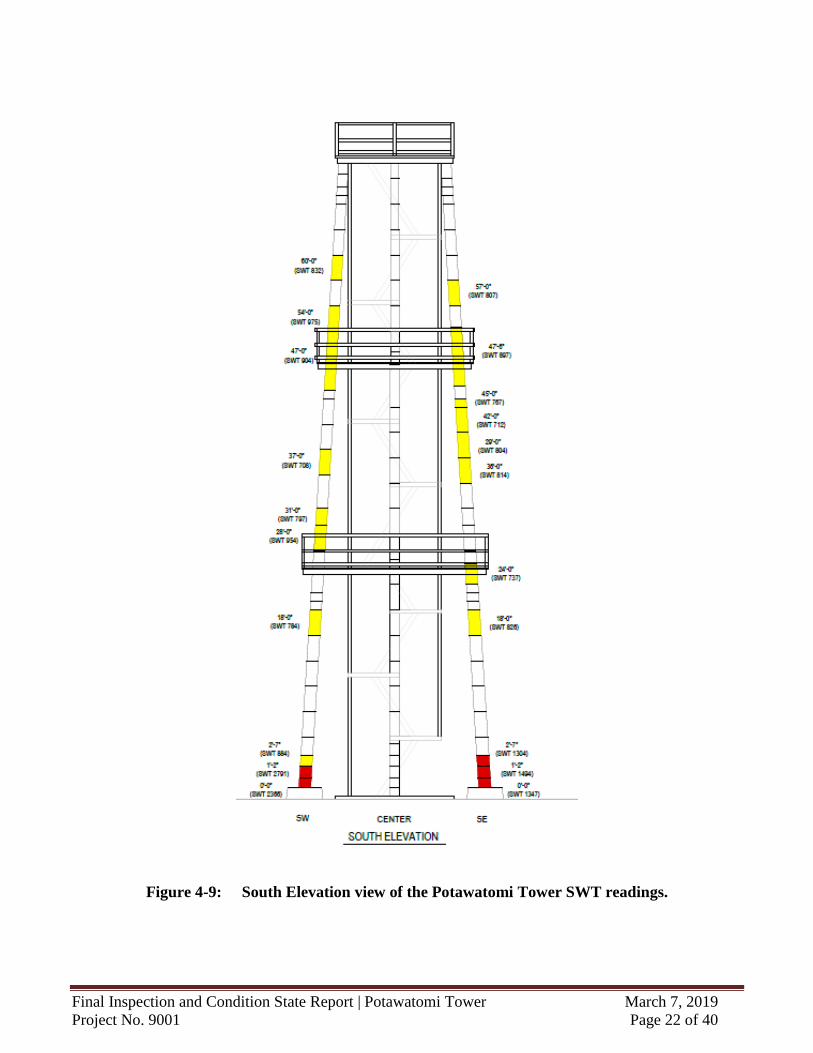
Figure 4-9: South Elevation view of the Potawatomi Tower SWT readings.
Final Inspection and Condition State Report | Potawatomi Tower March 7, 2019
Project No. 9001 Page 23 of 40
5.0 CORE SAMPLE TEST RESULTS
5.1 Timber Cores
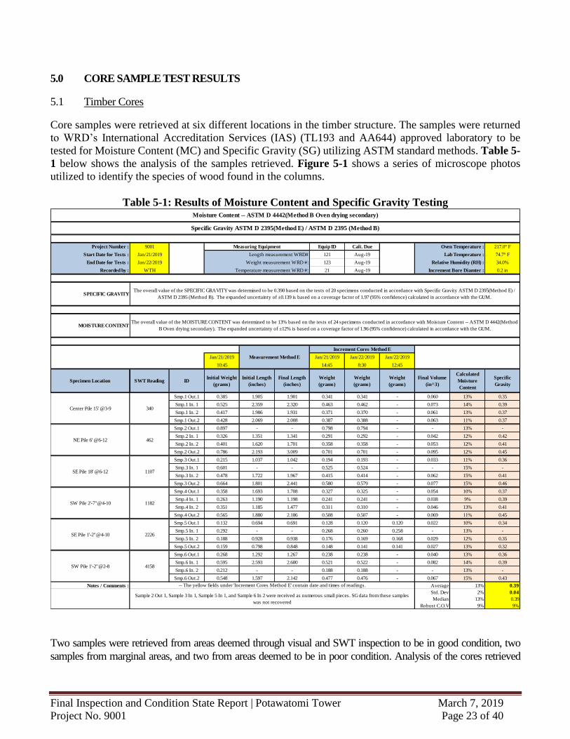
Core samples were retrieved at six different locations in the timber structure. The samples were returned
to WRD’s International Accreditation Services (IAS) (TL193 and AA644) approved laboratory to be
tested for Moisture Content (MC) and Specific Gravity (SG) utilizing ASTM standard methods. Table 5-
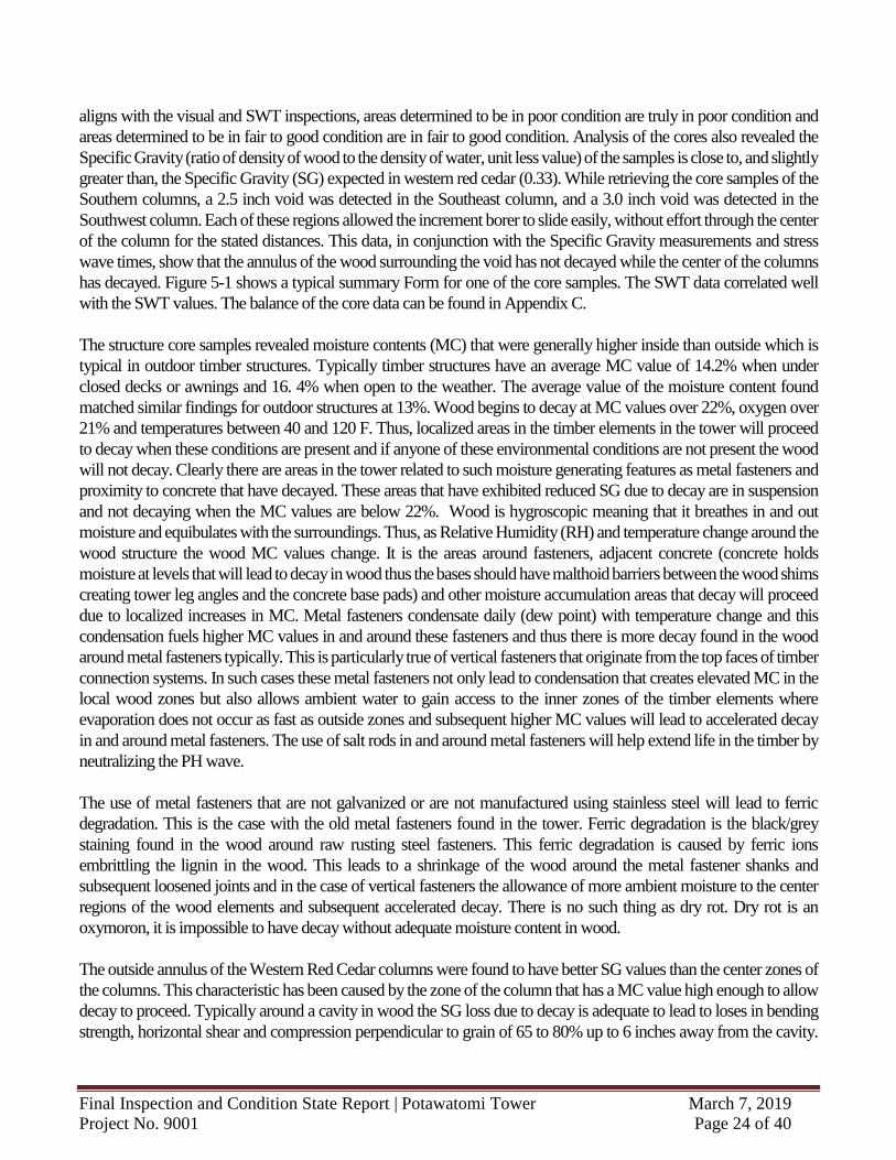
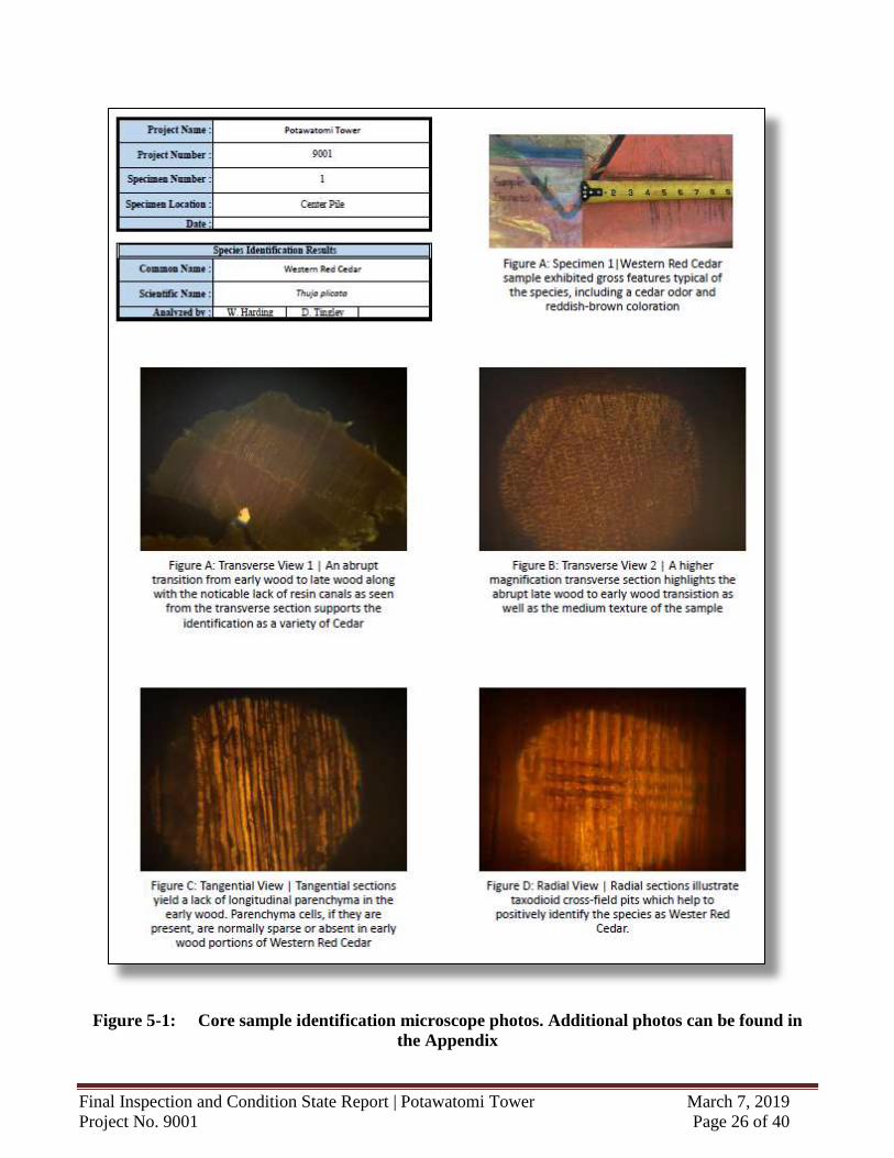
1 below shows the analysis of the samples retrieved. Figure 5-1 shows a series of microscope photos
utilized to identify the species of wood found in the columns.
Table 5-1: Results of Moisture Content and Specific Gravity Testing
Two samples were retrieved from areas deemed through visual and SWT inspection to be in good condition, two
samples from marginal areas, and two from areas deemed to be in poor condition. Analysis of the cores retrieved
Project Number : 9001 Equip ID Cali. Due 217.0° F
Start Date for Tests : Jan/21/2019 121 Aug-19 74.7° F
End Date for Tests : Jan/22/2019 123 Aug-19 34.0%
Recorded by : WTH 21 Aug-19 0.2 in
Jan/21/2019 Jan/21/2019 Jan/22/2019 Jan/22/2019
10:45 14:45 8:30 12:45
Specimen Location SWT Reading IDInitial Weight
(grams)
Initial Length
(inches)
Final Length
(inches)
Weight
(grams)
Weight
(grams)
Weight
(grams)
Final Volume
(in^3)
Calculated
Moisture
Content
Specific
Gravity
Smp.1 Out.1 0.385 1.905 1.901 0.341 0.341 - 0.060 13% 0.35
Smp.1 In. 1 0.525 2.359 2.320 0.463 0.462 - 0.073 14% 0.39
Smp.1 In. 2 0.417 1.986 1.931 0.371 0.370 - 0.061 13% 0.37
Smp.1 Out.2 0.428 2.069 2.008 0.387 0.388 - 0.063 11% 0.37
Smp.2 Out.1 0.897 - - 0.798 0.794 - - 13% -
Smp.2 In. 1 0.326 1.351 1.341 0.291 0.292 - 0.042 12% 0.42
Smp.2 In. 2 0.401 1.620 1.701 0.358 0.358 - 0.053 12% 0.41
Smp.2 Out.2 0.786 2.193 3.009 0.701 0.701 - 0.095 12% 0.45
Smp.3 Out.1 0.215 1.037 1.042 0.194 0.193 - 0.033 11% 0.36
Smp.3 In. 1 0.601 - - 0.525 0.524 - - 15% -
Smp.3 In. 2 0.478 1.722 1.967 0.415 0.414 - 0.062 15% 0.41
Smp.3 Out.2 0.664 1.801 2.441 0.580 0.579 - 0.077 15% 0.46
Smp.4 Out.1 0.358 1.693 1.708 0.327 0.325 - 0.054 10% 0.37
Smp.4 In. 1 0.263 1.190 1.198 0.241 0.241 - 0.038 9% 0.39
Smp.4 In. 2 0.351 1.185 1.477 0.311 0.310 - 0.046 13% 0.41
Smp.4 Out.2 0.565 1.880 2.186 0.508 0.507 - 0.069 11% 0.45
Smp.5 Out.1 0.132 0.694 0.691 0.128 0.120 0.120 0.022 10% 0.34
Smp.5 In. 1 0.292 - - 0.268 0.260 0.258 - 13% -
Smp.5 In. 2 0.188 0.928 0.938 0.176 0.169 0.168 0.029 12% 0.35
Smp.5 Out.2 0.159 0.798 0.848 0.148 0.141 0.141 0.027 13% 0.32
Smp.6 Out.1 0.268 1.292 1.267 0.238 0.238 - 0.040 13% 0.36
Smp.6 In. 1 0.595 2.593 2.600 0.521 0.522 - 0.082 14% 0.39
Smp.6 In. 2 0.212 - - 0.188 0.188 - - 13% -
Smp.6 Out.2 0.548 1.597 2.142 0.477 0.476 - 0.067 15% 0.43
Notes / Comments : Average 13% 0.39
Std. Dev 2% 0.04
Median 13% 0.39
Robust C.O.V 9% 9%
Measurement Method E
Increment Cores Method E
The overall value of the MOISTURE CONTENT was determined to be 13% based on the tests of 24 specimens conducted in accordance with Moisture Content -- ASTM D 4442(Method
B Oven drying secondary). The expanded uncertainty of ±12% is based on a coverage factor of 1.96 (95% confidence) calculated in accordance with the GUM.
-- The yellow fields under 'Increment Cores Method E' contain date and times of readings.
Sample 2 Out 1, Sample 3 In 1, Sample 5 In 1, and Sample 6 In 2 were received as numerous small pieces. SG data from these samples
was not recovered
MOISTURE CONTENT
Relative Humidity (RH) :
Increment Bore Diamter :
SPECIFIC GRAVITYThe overall value of the SPECIFIC GRAVITY was determined to be 0.390 based on the tests of 20 specimens conducted in accordance with Specific Gravity ASTM D 2395(Method E) /
ASTM D 2395 (Method B). The expanded uncertainty of ±0.139 is based on a coverage factor of 1.97 (95% confidence) calculated in accordance with the GUM.
Moisture Content -- ASTM D 4442(Method B Oven drying secondary)
Specific Gravity ASTM D 2395(Method E) / ASTM D 2395 (Method B)
Oven Temperature :
Lab Temperature :
Measuring Equipment
Length measurement WRD#
Weight measurement WRD #:
Temperature measurement WRD #:
NE Pile 6' @6-12
Center Pile 15' @3-9
4158
2226
1182
1107
462
340
SW Pile 1'-2"@2-8
SE Pile 1'-2"@4-10
SW Pile 2'-7"@4-10
SE Pile 18' @6-12
Final Inspection and Condition State Report | Potawatomi Tower March 7, 2019
Project No. 9001 Page 24 of 40
aligns with the visual and SWT inspections, areas determined to be in poor condition are truly in poor condition and
areas determined to be in fair to good condition are in fair to good condition. Analysis of the cores also revealed the
Specific Gravity (ratio of density of wood to the density of water, unit less value) of the samples is close to, and slightly
greater than, the Specific Gravity (SG) expected in western red cedar (0.33). While retrieving the core samples of the
Southern columns, a 2.5 inch void was detected in the Southeast column, and a 3.0 inch void was detected in the
Southwest column. Each of these regions allowed the increment borer to slide easily, without effort through the center
of the column for the stated distances. This data, in conjunction with the Specific Gravity measurements and stress
wave times, show that the annulus of the wood surrounding the void has not decayed while the center of the columns
has decayed. Figure 5-1 shows a typical summary Form for one of the core samples. The SWT data correlated well
with the SWT values. The balance of the core data can be found in Appendix C.
The structure core samples revealed moisture contents (MC) that were generally higher inside than outside which is
typical in outdoor timber structures. Typically timber structures have an average MC value of 14.2% when under
closed decks or awnings and 16. 4% when open to the weather. The average value of the moisture content found
matched similar findings for outdoor structures at 13%. Wood begins to decay at MC values over 22%, oxygen over
21% and temperatures between 40 and 120 F. Thus, localized areas in the timber elements in the tower will proceed
to decay when these conditions are present and if anyone of these environmental conditions are not present the wood
will not decay. Clearly there are areas in the tower related to such moisture generating features as metal fasteners and
proximity to concrete that have decayed. These areas that have exhibited reduced SG due to decay are in suspension
and not decaying when the MC values are below 22%. Wood is hygroscopic meaning that it breathes in and out
moisture and equibulates with the surroundings. Thus, as Relative Humidity (RH) and temperature change around the
wood structure the wood MC values change. It is the areas around fasteners, adjacent concrete (concrete holds
moisture at levels that will lead to decay in wood thus the bases should have malthoid barriers between the wood shims
creating tower leg angles and the concrete base pads) and other moisture accumulation areas that decay will proceed
due to localized increases in MC. Metal fasteners condensate daily (dew point) with temperature change and this
condensation fuels higher MC values in and around these fasteners and thus there is more decay found in the wood
around metal fasteners typically. This is particularly true of vertical fasteners that originate from the top faces of timber
connection systems. In such cases these metal fasteners not only lead to condensation that creates elevated MC in the
local wood zones but also allows ambient water to gain access to the inner zones of the timber elements where
evaporation does not occur as fast as outside zones and subsequent higher MC values will lead to accelerated decay
in and around metal fasteners. The use of salt rods in and around metal fasteners will help extend life in the timber by
neutralizing the PH wave.
The use of metal fasteners that are not galvanized or are not manufactured using stainless steel will lead to ferric
degradation. This is the case with the old metal fasteners found in the tower. Ferric degradation is the black/grey
staining found in the wood around raw rusting steel fasteners. This ferric degradation is caused by ferric ions
embrittling the lignin in the wood. This leads to a shrinkage of the wood around the metal fastener shanks and
subsequent loosened joints and in the case of vertical fasteners the allowance of more ambient moisture to the center
regions of the wood elements and subsequent accelerated decay. There is no such thing as dry rot. Dry rot is an
oxymoron, it is impossible to have decay without adequate moisture content in wood.
The outside annulus of the Western Red Cedar columns were found to have better SG values than the center zones of
the columns. This characteristic has been caused by the zone of the column that has a MC value high enough to allow
decay to proceed. Typically around a cavity in wood the SG loss due to decay is adequate to lead to loses in bending
strength, horizontal shear and compression perpendicular to grain of 65 to 80% up to 6 inches away from the cavity.
Final Inspection and Condition State Report | Potawatomi Tower March 7, 2019
Project No. 9001 Page 25 of 40
The radius of reduced strength around extensive decay cavities or zones in timber is generally determined by the
location of treatment zones or zones of reduced MC. In the tower columns the outer zones of wood in the columns are
evaporating water and thus the MC value is lower outside (witnessed in the core samples) than inside. The sound
annulus thickness is determined by the MC gradient from outside to inside the column. The point at which the MC
value exceeds 22% MC working from outside towards the inside is the point at which decay will stop. This
characteristic is also present around condensating metal fasteners. Alternatively the point at which the wood has some
sort of adequate treatment will be the point at which decay is no longer function.
Final Inspection and Condition State Report | Potawatomi Tower March 7, 2019
Project No. 9001 Page 26 of 40
Figure 5-1: Core sample identification microscope photos. Additional photos can be found in
the Appendix
Final Inspection and Condition State Report | Potawatomi Tower March 7, 2019
Project No. 9001 Page 27 of 40
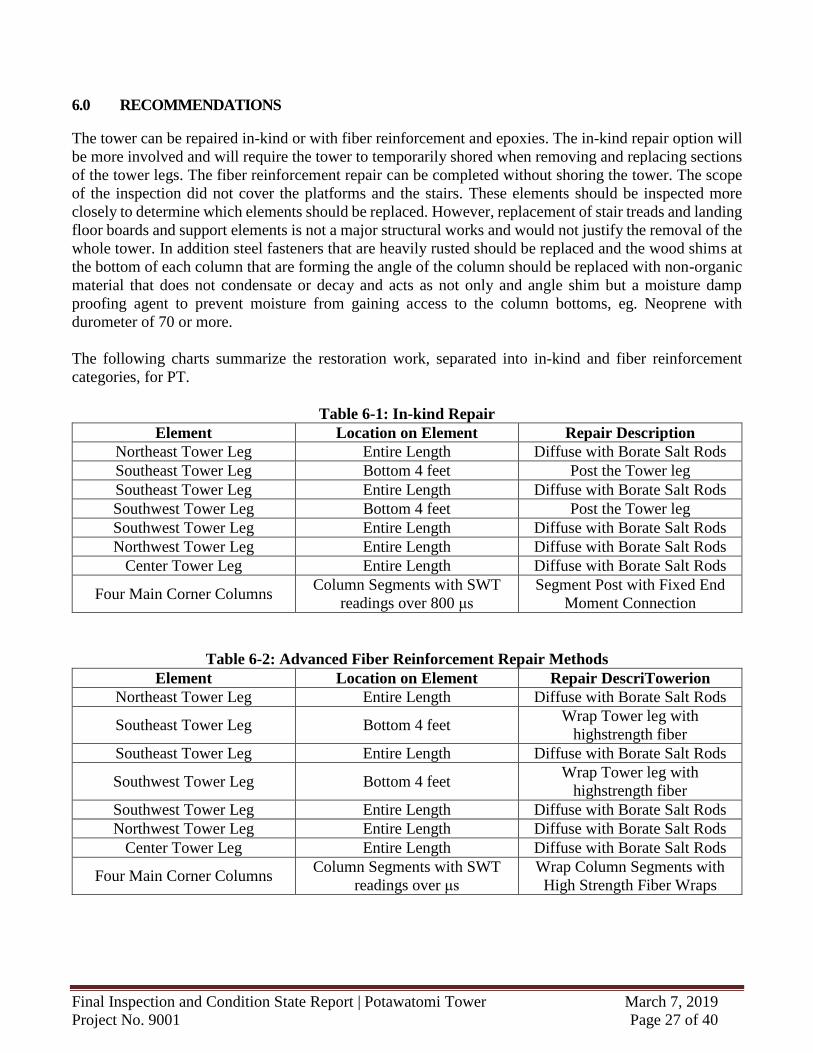
6.0 RECOMMENDATIONS
The tower can be repaired in-kind or with fiber reinforcement and epoxies. The in-kind repair option will
be more involved and will require the tower to temporarily shored when removing and replacing sections
of the tower legs. The fiber reinforcement repair can be completed without shoring the tower. The scope
of the inspection did not cover the platforms and the stairs. These elements should be inspected more
closely to determine which elements should be replaced. However, replacement of stair treads and landing
floor boards and support elements is not a major structural works and would not justify the removal of the
whole tower. In addition steel fasteners that are heavily rusted should be replaced and the wood shims at
the bottom of each column that are forming the angle of the column should be replaced with non-organic
material that does not condensate or decay and acts as not only and angle shim but a moisture damp
proofing agent to prevent moisture from gaining access to the column bottoms, eg. Neoprene with
durometer of 70 or more.
The following charts summarize the restoration work, separated into in-kind and fiber reinforcement
categories, for PT.
Table 6-1: In-kind Repair
Element Location on Element Repair Description
Northeast Tower Leg Entire Length Diffuse with Borate Salt Rods
Southeast Tower Leg Bottom 4 feet Post the Tower leg
Southeast Tower Leg Entire Length Diffuse with Borate Salt Rods
Southwest Tower Leg Bottom 4 feet Post the Tower leg
Southwest Tower Leg Entire Length Diffuse with Borate Salt Rods
Northwest Tower Leg Entire Length Diffuse with Borate Salt Rods
Center Tower Leg Entire Length Diffuse with Borate Salt Rods
Four Main Corner Columns Column Segments with SWT
readings over 800 μs
Segment Post with Fixed End
Moment Connection
Table 6-2: Advanced Fiber Reinforcement Repair Methods
Element Location on Element Repair DescriTowerion
Northeast Tower Leg Entire Length Diffuse with Borate Salt Rods
Southeast Tower Leg Bottom 4 feet Wrap Tower leg with
highstrength fiber
Southeast Tower Leg Entire Length Diffuse with Borate Salt Rods
Southwest Tower Leg Bottom 4 feet Wrap Tower leg with
highstrength fiber
Southwest Tower Leg Entire Length Diffuse with Borate Salt Rods
Northwest Tower Leg Entire Length Diffuse with Borate Salt Rods
Center Tower Leg Entire Length Diffuse with Borate Salt Rods
Four Main Corner Columns Column Segments with SWT
readings over μs
Wrap Column Segments with
High Strength Fiber Wraps
Final Inspection and Condition State Report | Potawatomi Tower March 7, 2019
Project No. 9001 Page 28 of 40
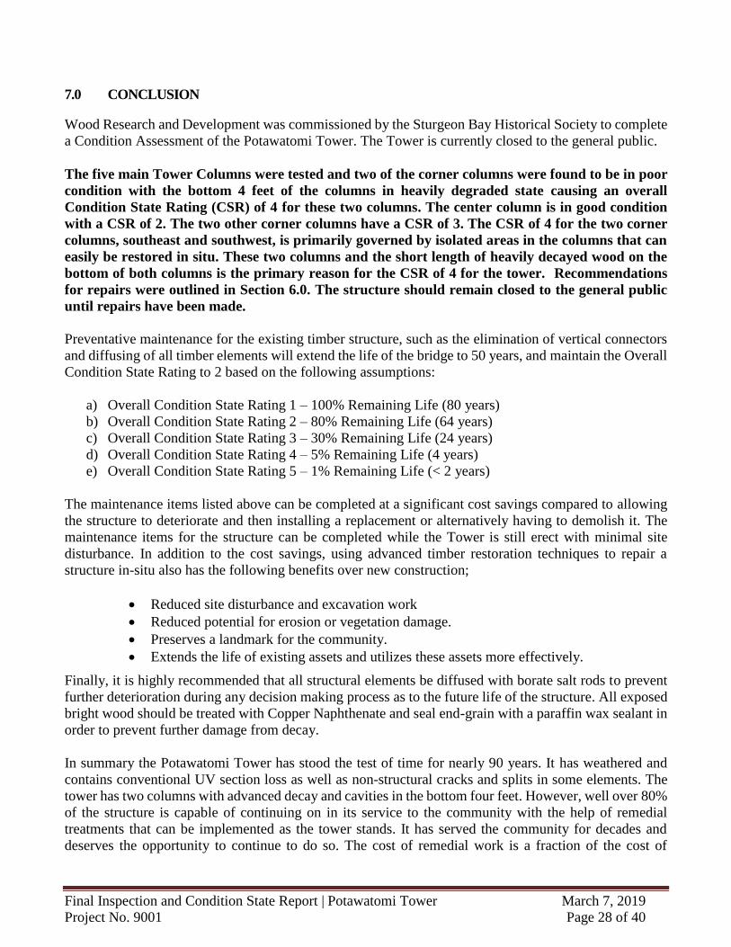
7.0 CONCLUSION
Wood Research and Development was commissioned by the Sturgeon Bay Historical Society to complete
a Condition Assessment of the Potawatomi Tower. The Tower is currently closed to the general public.
The five main Tower Columns were tested and two of the corner columns were found to be in poor
condition with the bottom 4 feet of the columns in heavily degraded state causing an overall
Condition State Rating (CSR) of 4 for these two columns. The center column is in good condition
with a CSR of 2. The two other corner columns have a CSR of 3. The CSR of 4 for the two corner
columns, southeast and southwest, is primarily governed by isolated areas in the columns that can
easily be restored in situ. These two columns and the short length of heavily decayed wood on the
bottom of both columns is the primary reason for the CSR of 4 for the tower. Recommendations
for repairs were outlined in Section 6.0. The structure should remain closed to the general public
until repairs have been made.
Preventative maintenance for the existing timber structure, such as the elimination of vertical connectors
and diffusing of all timber elements will extend the life of the bridge to 50 years, and maintain the Overall
Condition State Rating to 2 based on the following assumptions:
a) Overall Condition State Rating 1 – 100% Remaining Life (80 years)
b) Overall Condition State Rating 2 – 80% Remaining Life (64 years)
c) Overall Condition State Rating 3 – 30% Remaining Life (24 years)
d) Overall Condition State Rating 4 – 5% Remaining Life (4 years)
e) Overall Condition State Rating 5 – 1% Remaining Life (< 2 years)
The maintenance items listed above can be completed at a significant cost savings compared to allowing
the structure to deteriorate and then installing a replacement or alternatively having to demolish it. The
maintenance items for the structure can be completed while the Tower is still erect with minimal site
disturbance. In addition to the cost savings, using advanced timber restoration techniques to repair a
structure in-situ also has the following benefits over new construction;
Reduced site disturbance and excavation work
Reduced potential for erosion or vegetation damage.
Preserves a landmark for the community.
Extends the life of existing assets and utilizes these assets more effectively.
Finally, it is highly recommended that all structural elements be diffused with borate salt rods to prevent
further deterioration during any decision making process as to the future life of the structure. All exposed
bright wood should be treated with Copper Naphthenate and seal end-grain with a paraffin wax sealant in
order to prevent further damage from decay.
In summary the Potawatomi Tower has stood the test of time for nearly 90 years. It has weathered and
contains conventional UV section loss as well as non-structural cracks and splits in some elements. The
tower has two columns with advanced decay and cavities in the bottom four feet. However, well over 80%
of the structure is capable of continuing on in its service to the community with the help of remedial
treatments that can be implemented as the tower stands. It has served the community for decades and
deserves the opportunity to continue to do so. The cost of remedial work is a fraction of the cost of
Final Inspection and Condition State Report | Potawatomi Tower March 7, 2019
Project No. 9001 Page 29 of 40
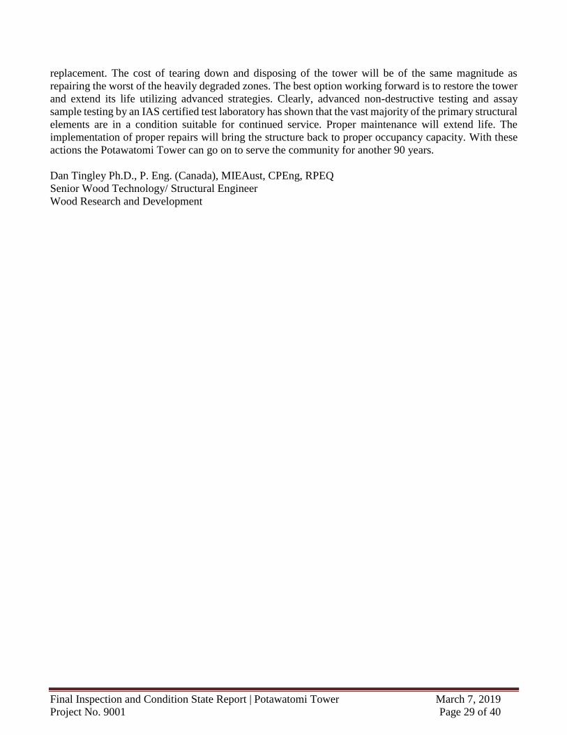
replacement. The cost of tearing down and disposing of the tower will be of the same magnitude as
repairing the worst of the heavily degraded zones. The best option working forward is to restore the tower
and extend its life utilizing advanced strategies. Clearly, advanced non-destructive testing and assay
sample testing by an IAS certified test laboratory has shown that the vast majority of the primary structural
elements are in a condition suitable for continued service. Proper maintenance will extend life. The
implementation of proper repairs will bring the structure back to proper occupancy capacity. With these
actions the Potawatomi Tower can go on to serve the community for another 90 years.
Dan Tingley Ph.D., P. Eng. (Canada), MIEAust, CPEng, RPEQ
Senior Wood Technology/ Structural Engineer
Wood Research and Development
Final Inspection and Condition State Report | Potawatomi Tower March 7, 2019
Project No. 9001 Page 30 of 40
APPENDIX
Appendix A – SWT Summary Drawings
Appendix B – SWT Data
Appendix C – Core Data
Final Inspection and Condition State Report | Potawatomi Tower March 7, 2019
Project No. 9001 Page 31 of 40
Appendix A – SWT Summary Drawings
Final Inspection and Condition State Report | Potawatomi Tower March 7, 2019
Project No. 9001 Page 32 of 40
Appendix B – SWT Data
Color GA Length
Length : 51.00 feet
End 1 Dia. : 14.50 inches
End 2 Dia. : 10.00 inches
0 1.17 2.58 3.83 5.25 9 12 15 18 21 24 - - -
14.5 14.4 14.3 14.2 14.0 13.7 13.4 13.2 12.9 12.6 12.4 - - -
6/12 Adjusted 396 418 442 535 - 350 341 316 410 454 439 - - -
1/11 Adjusted - - - - - - - - - - - - - -
2/8 Adjusted 329 - 514 - - - - - - - - - - -
3/9 Adjusted - - - - 468 368 316 310 366 318 487 - - -
4/10 Adjusted 407 - 457 - - - - - - - - - - -
5/7 Adjusted - - - - - - - - - - - - - -
Length : 51.00 feet
End 1 Dia. : 14.50 inches
End 2 Dia. : 10.00 inches
27 30 33 36 39 42 45 50 - - - - - -
12.1 11.9 11.6 11.3 11.1 10.8 10.5 10.1 - - - - - -
6/12 Adjusted 342 492 367 397 399 391 441 359 - - - - - -
1/11 Adjusted - - - - - - - - - - - - - -
2/8 Adjusted - - - - - - - 307 - - - - - -
3/9 Adjusted 418 435 367 380 381 317 301 641 - - - - - -
4/10 Adjusted - - - - - - - 487 - - - - - -
5/7 Adjusted - - - - - - - - - - - - - -
Length : 24.00 feet
Height : 7.50 inches
Width : 7.50 inches
51.5 54 57 60 63 66 69 72 75 - - - - -
- - - - -
6/12 Adjusted 410 272 426 432 258 258 555 470 528 - - - - -
1/11 Adjusted - - - - - - - - - - - - - -
2/8 Adjusted - - - - - - - - - - - - - -
3/9 Adjusted 456 338 630 645 616 590 394 454 470 - - - - -
4/10 Adjusted - - - - - - - - - - - - - -
5/7 Adjusted - - - - - - - - - - - - - -
Length : 75.00 feet
End 1 Dia. : 17.50 inches
End 2 Dia. : 10.00 inches
0 1.42 2.58 3.83 6 9 12 15 18 21 22 23 - -
17.5 17.4 17.2 17.1 16.9 16.6 16.3 16.0 15.7 15.4 15.3 15.2 - -
6/12 Adjusted 559 305 396 437 473 421 417 425 397 533 442 - - -
1/11 Adjusted - - - - - - - - - - - - - -
2/8 Adjusted 385 - 390 - - - - - - - 562 585 - -
3/9 Adjusted - - - - 439 436 495 551 600 598 544 703 - -
4/10 Adjusted 311 - 352 - - - - - - - 479 521 - -
5/7 Adjusted - - - - - - - - - - - - - -
Location (feet) :
Diameter (inches) :
Comments :
Visual Condition
Component : Column Location (Sequence #) :Poor
Type : Log Member Geometry : Round
Location | Number : Tier 1 Component Number : Northwest
Location (feet) :
Comments :
3 Component Number : Center Visual Condition
Component : Column Location (Sequence #) :Poor
Type : Log Member Geometry : Rectangular
Location | Number : Tier
Location (feet) :
Diameter (inches) :
Comments :
Center Visual Condition
Component : Column Location (Sequence #) :Poor
Type : Log Member Geometry : Round
Location | Number : Tier 2 Component Number :
Type :
Location (feet) :
Diameter (inches) :
SWT Chart - Color Code Key
Sturgeon Bay, Wisconsin Description
Clock Direction :
12 inUS Units
Jan/14/2019 - Jan/16/2019
Adjusted SWT Data
YELLOW
Structure Name :Location (City, St./Prov.) :
Location (Country) :
RoundLog Member Geometry :
SWT values over 1000 - Immediate restoration or replacment
SWT values between 700 and 999 - Elements require caution in use and
Frequent Inspection12 in
Unit of Measure :
Date(s) of Inspection :
12 = North
United StatesRED
Poor
Location | Number :
Component :
1
Comments :
Tier Component Number : Center Visual Condition
Column Location (Sequence #) :
Final Inspection and Condition State Report | Potawatomi Tower March 7, 2019
Project No. 9001 Page 33 of 40
Length : 75.00 feet
End 1 Dia. : 17.50 inches
End 2 Dia. : 10.00 inches
28 31 34 37 40 43 46 47 - - - - - -
14.7 14.4 14.1 13.8 13.5 13.2 12.9 12.8 - - - - - -
6/12 Adjusted 613 381 482 505 524 472 395 - - - - - - -
1/11 Adjusted - - - - - - - - - - - - - -
2/8 Adjusted - - - - - - 621 543 - - - - - -
3/9 Adjusted 622 596 500 450 476 504 540 661 - - - - - -
4/10 Adjusted - - - - - - 512 577 - - - - - -
5/7 Adjusted - - - - - - - - - - - - - -
Length : 75.00 feet
End 1 Dia. : 17.50 inches
End 2 Dia. : 10.00 inches
54 57 60 63 66 69 72 - - - - - - -
12.1 11.8 11.5 11.2 10.9 10.6 10.3 - - - - - - -
6/12 Adjusted 632 473 788 414 701 464 482 - - - - - - -
1/11 Adjusted - - - - - - - - - - - - - -
2/8 Adjusted - - - - - - - - - - - - - -
3/9 Adjusted 710 713 343 431 455 680 562 - - - - - - -
4/10 Adjusted - - - - - - - - - - - - - -
5/7 Adjusted - - - - - - - - - - - - - -
Length : 75.00 feet
End 1 Dia. : 17.00 inches
End 2 Dia. : 10.00 inches
0 1.17 2.58 3.83 6 9 12 15 18 21 22 23 - -
17.0 16.9 16.8 16.6 16.4 16.2 15.9 15.6 15.3 15.0 14.9 14.9 - -
6/12 Adjusted 440 420 401 406 337 365 539 545 549 489 458 - - -
1/11 Adjusted - - - - - - - - - - - - - -
2/8 Adjusted 443 - 447 - - - - - - - 522 507 - -
3/9 Adjusted - - - - 405 400 407 540 633 586 459 528 - -
4/10 Adjusted 428 - 356 - - - - - - - 569 549 - -
5/7 Adjusted - - - - - - - - - - - - - -
Length : 75.00 feet
End 1 Dia. : 17.00 inches
End 2 Dia. : 10.00 inches
28 31 34 37 40 43 46 47 - - - - - -
14.4 14.1 13.8 13.5 13.3 13.0 12.7 12.6 - - - - - -
6/12 Adjusted 455 506 462 454 490 665 685 - - - - - - -
1/11 Adjusted - - - - - - - - - - - - - -
2/8 Adjusted - - - - - - 542 481 - - - - - -
3/9 Adjusted 492 443 532 500 685 550 492 528 - - - - - -
4/10 Adjusted - - - - - - 760 470 - - - - - -
5/7 Adjusted - - - - - - - - - - - - - -
Length : 75.00 feet
End 1 Dia. : 17.00 inches
End 2 Dia. : 10.00 inches
54 57 60 63 66 69 72 74 - - - - - -
12.0 11.7 11.4 11.1 10.8 10.6 10.3 10.1 - - - - - -
6/12 Adjusted 947 632 565 423 641 540 481 - - - - - - -
1/11 Adjusted - - - - - - - - - - - - - -
2/8 Adjusted - - - - - - 561 - - - - - - -
3/9 Adjusted 655 817 467 628 530 592 609 289 - - - - - -
4/10 Adjusted - - - - - - 490 - - - - - - -
5/7 Adjusted - - - - - - - - - - - - - -
Comments :
Log Member Geometry : Round
Location (feet) :
Diameter (inches) :
Location | Number : Tier 2 Component Number : Northeast Visual Condition
Component : Column Location (Sequence #) :Poor
Type :
Comments :
Log Member Geometry : Round
Location (feet) :
Diameter (inches) :
Location | Number : Tier 2 Component Number : Northwest Visual Condition
Component : Column Location (Sequence #) :Poor
Type :
Location (feet) :
Diameter (inches) :
Comments :
Component : Column Location (Sequence #) :Poor
Type : Log Member Geometry : Round
Location | Number : Tier 3 Component Number : Northeast Visual Condition
Location (feet) :
Diameter (inches) :
Comments :
Component : Column Location (Sequence #) :Poor
Type : Log Member Geometry : Round
Location | Number : Tier 1 Component Number : Northeast Visual Condition
Location (feet) :
Diameter (inches) :
Comments :
Component : Column Location (Sequence #) :Poor
Type : Log Member Geometry : Round
Location | Number : Tier 3 Component Number : Northwest Visual Condition
Final Inspection and Condition State Report | Potawatomi Tower March 7, 2019
Project No. 9001 Page 34 of 40
Length : 75.00 feet
End 1 Dia. : 18.00 inches
End 2 Dia. : 10.00 inches
0 1.17 2.58 3.83 6 9 12 15 18 21 22 23 - -
18.0 17.9 17.7 17.6 17.4 17.0 16.7 16.4 16.1 15.8 15.7 15.5 - -
6/12 Adjusted 1539 2323 829 480 419 321 665 604 784 477 497 - - -
1/11 Adjusted - - - - - - - - - - - - - -
2/8 Adjusted 2366 2791 884 456 404 - - - - - 520 - - -
3/9 Adjusted - - - - 384 380 580 491 622 406 543 464 - -
4/10 Adjusted 1089 681 800 432 487 - - - - - 474 554 - -
5/7 Adjusted - - - - - - - - - - - - - -
Length : 75.00 feet
End 1 Dia. : 18.00 inches
End 2 Dia. : 10.00 inches
28 31 34 37 40 43 46 47 - - - - - -
15.0 14.7 14.4 14.1 13.7 13.4 13.1 13.0 - - - - - -
6/12 Adjusted 865 256 531 587 624 527 573 - - - - - - -
1/11 Adjusted - - - - - - - - - - - - - -
2/8 Adjusted - - - - - - 629 475 - - - - - -
3/9 Adjusted 954 797 530 708 509 547 648 904 - - - - - -
4/10 Adjusted - - - - - - 543 515 - - - - - -
5/7 Adjusted - - - - - - - - - - - - - -
Length : 75.00 feet
End 1 Dia. : 18.00 inches
End 2 Dia. : 10.00 inches
54 57 60 63 66 69 71 72.5 - - - - - -
12.2 11.9 11.6 11.3 11.0 10.6 10.4 10.3 - - - - - -
6/12 Adjusted 377 576 801 655 423 650 569 - - - - - - -
1/11 Adjusted - - - - - - - - - - - - - -
2/8 Adjusted - - - - - - 310 - - - - - - -
3/9 Adjusted 975 689 832 537 630 664 473 341 - - - - - -
4/10 Adjusted - - - - - - 464 - - - - - - -
5/7 Adjusted - - - - - - - - - - - - - -
Length : 75.00 feet
End 1 Dia. : 18.00 inches
End 2 Dia. : 10.00 inches
0 1.17 2.58 3.83 6 9 12 15 18 21 22 23 24 -
18.0 17.9 17.7 17.6 17.4 17.0 16.7 16.4 16.1 15.8 15.7 15.5 15.4 -
6/12 Adjusted 1347 987 622 485 422 425 504 490 826 688 651 - - -
1/11 Adjusted - - - - - - - - - - - - - -
2/8 Adjusted 1071 1223 471 509 432 - - - - - 695 675 475 -
3/9 Adjusted - - - - 313 368 431 589 697 695 586 506 737 -
4/10 Adjusted 420 1494 1304 423 576 - - - - - 468 341 459 -
5/7 Adjusted - - - - - - - - - - - - - -
Length : 75.00 feet
End 1 Dia. : 18.00 inches
End 2 Dia. : 10.00 inches
26.5 28 30 31 33 36 39 42 45 46 47.5 - - -
15.2 15.0 14.8 14.7 14.5 14.2 13.8 13.5 13.2 13.1 12.9 - - -
6/12 Adjusted 633 452 438 403 643 814 804 712 521 389 - - - -
1/11 Adjusted - - - - - - - - - - - - - -
2/8 Adjusted - - - - - - - - - 569 680 - - -
3/9 Adjusted 602 561 432 483 664 471 346 525 767 622 897 - - -
4/10 Adjusted - - - - - - - - - 417 800 - - -
5/7 Adjusted - - - - - - - - - - - - - -
Comments :
Log Member Geometry : Round
Location (feet) :
Diameter (inches) :
Location | Number : Tier 2 Component Number : Southwest Visual Condition
Component : Column Location (Sequence #) :Poor
Type :
Location (feet) :
Diameter (inches) :
Comments :
Component : Column Location (Sequence #) :Poor
Type : Log Member Geometry : Round
Location | Number : Tier 2 Component Number : Southeast Visual Condition
Location (feet) :
Diameter (inches) :
Comments :
Component : Column Location (Sequence #) :Poor
Type : Log Member Geometry : Round
Location | Number : Tier 1 Component Number : Southeast Visual Condition
Location (feet) :
Diameter (inches) :
Comments :
Component : Column Location (Sequence #) :Poor
Type : Log Member Geometry : Round
Location | Number : Tier 3 Component Number : Southwest Visual Condition
Location (feet) :
Diameter (inches) :
Comments :
Component : Column Location (Sequence #) :Poor
Type : Log Member Geometry : Round
Location | Number : Tier 1 Component Number : Southwest Visual Condition
Final Inspection and Condition State Report | Potawatomi Tower March 7, 2019
Project No. 9001 Page 35 of 40
Length : 75.00 feet
End 1 Dia. : 18.00 inches
End 2 Dia. : 10.00 inches
54 57 60 63 66 69 70 71 72 - - - - -
12.2 11.9 11.6 11.3 11.0 10.6 10.5 10.4 10.3 - - - - -
6/12 Adjusted 678 780 576 534 655 476 500 389 - - - - - -
1/11 Adjusted - - - - - - - - - - - - - -
2/8 Adjusted - - - - - - - - 621 - - - - -
3/9 Adjusted 413 807 697 487 660 451 457 563 583 - - - - -
4/10 Adjusted - - - - - - - - 471 - - - - -
5/7 Adjusted - - - - - - - - - - - - - -
Location (feet) :
Diameter (inches) :
Comments :
Component : Column Location (Sequence #) :Poor
Type : Log Member Geometry : Round
Location | Number : Tier 3 Component Number : Southeast Visual Condition

Final Inspection and Condition State Report | Potawatomi Tower March 7, 2019
Project No. 9001 Page 36 of 40
Final Inspection and Condition State Report | Potawatomi Tower March 7, 2019
Project No. 9001 Page 37 of 40
Appendix C – Core Test Data Results
Date :
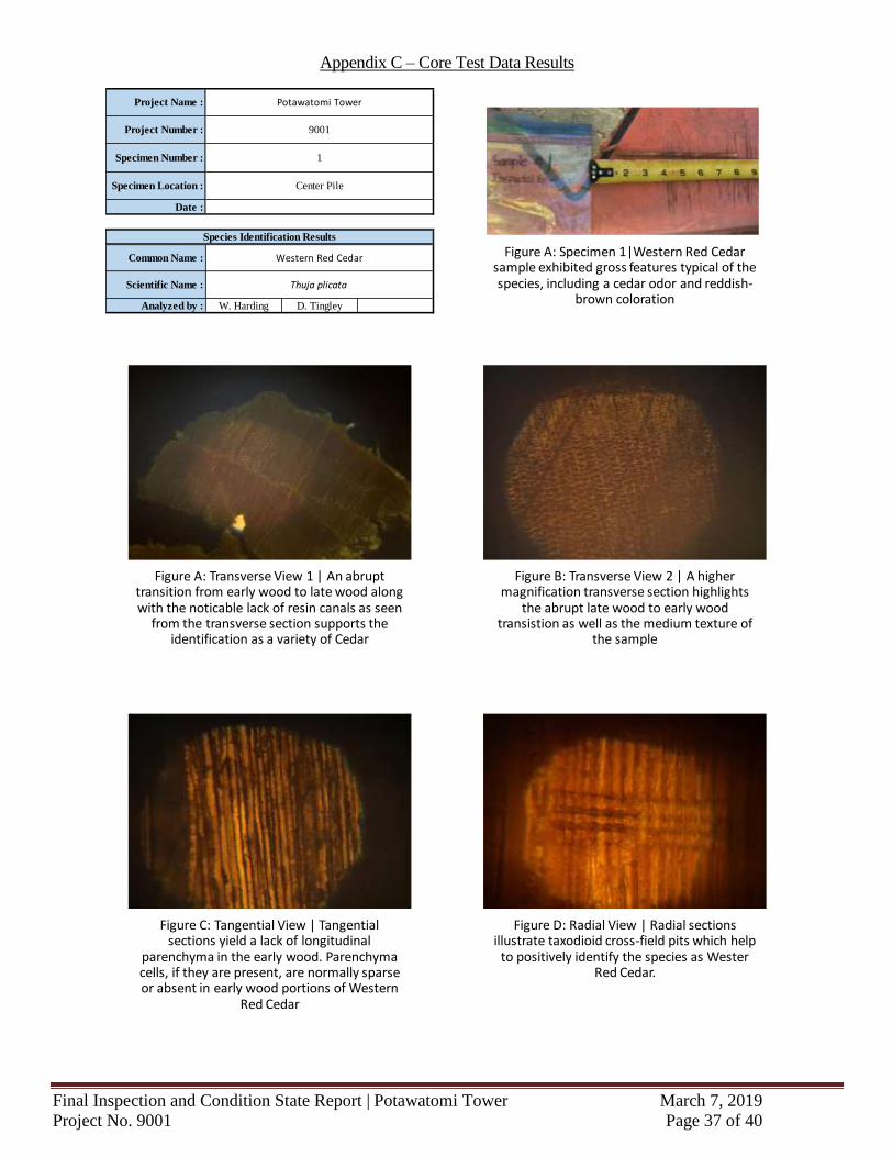
Analyzed by : W. Harding D. Tingley
Thuja plicataScientific Name :
Species Identification Results
Project Name :
Project Number :
Specimen Number :
Specimen Location : Center Pile
Potawatomi Tower
9001
1
Common Name : Western Red Cedar
Figure C: Tangential View | Tangential sections yield a lack of longitudinal
parenchyma in the early wood. Parenchyma cells, if they are present, are normally sparse or absent in early wood portions of Western
Red Cedar
Figure D: Radial View | Radial sections illustrate taxodioid cross-field pits which help
to positively identify the species as Wester Red Cedar.
Figure A: Transverse View 1 | An abrupt transition from early wood to late wood along with the noticable lack of resin canals as seen
from the transverse section supports the identification as a variety of Cedar
Figure B: Transverse View 2 | A higher magnification transverse section highlights
the abrupt late wood to early wood transistion as well as the medium texture of
the sample
Figure A: Specimen 1|Western Red Cedar sample exhibited gross features typical of the species, including a cedar odor and reddish-
brown coloration
Final Inspection and Condition State Report | Potawatomi Tower March 7, 2019
Project No. 9001 Page 38 of 40
Date :
Analyzed by : W. Harding D. Tingley
Thuja plicataScientific Name :
Species Identification Results
Project Name :
Project Number :
Specimen Number :
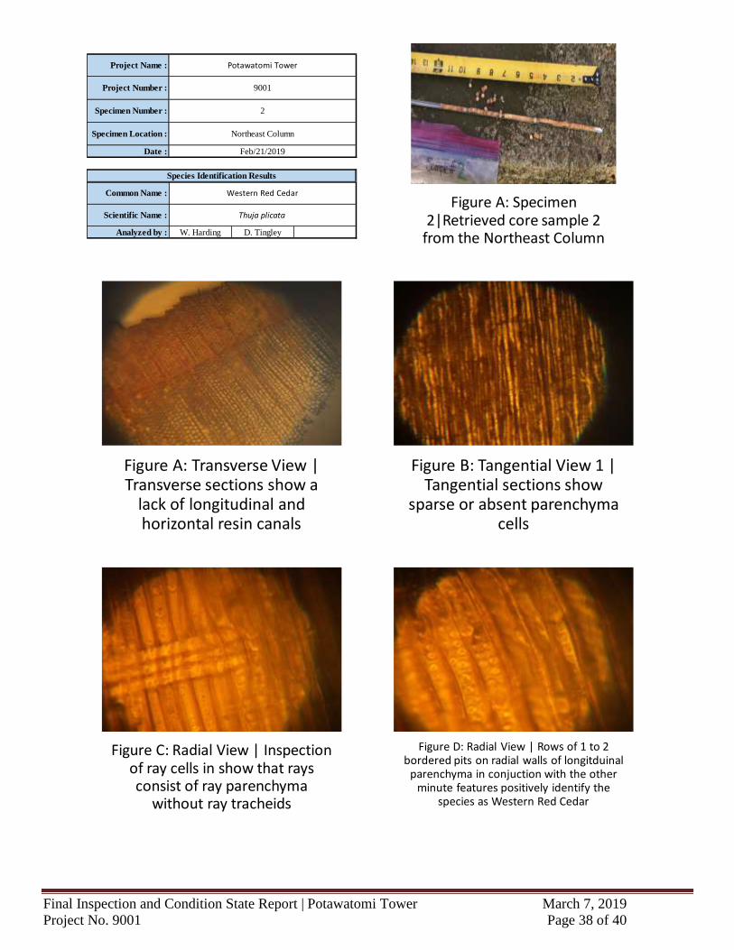
Specimen Location : Northeast Column
Potawatomi Tower
9001
2
Feb/21/2019
Common Name : Western Red Cedar
Figure C: Radial View | Inspection of ray cells in show that rays consist of ray parenchyma
without ray tracheids
Figure D: Radial View | Rows of 1 to 2 bordered pits on radial walls of longitduinal
parenchyma in conjuction with the other minute features positively identify the
species as Western Red Cedar
Figure A: Transverse View | Transverse sections show a
lack of longitudinal and horizontal resin canals
Figure B: Tangential View 1 | Tangential sections show
sparse or absent parenchyma cells
Figure A: Specimen 2|Retrieved core sample 2
from the Northeast Column
Final Inspection and Condition State Report | Potawatomi Tower March 7, 2019
Project No. 9001 Page 39 of 40
Date :
Analyzed by : W. Harding D. Tingley
Thuja plicataScientific Name :
Species Identification Results
Project Name :
Project Number :
Specimen Number :
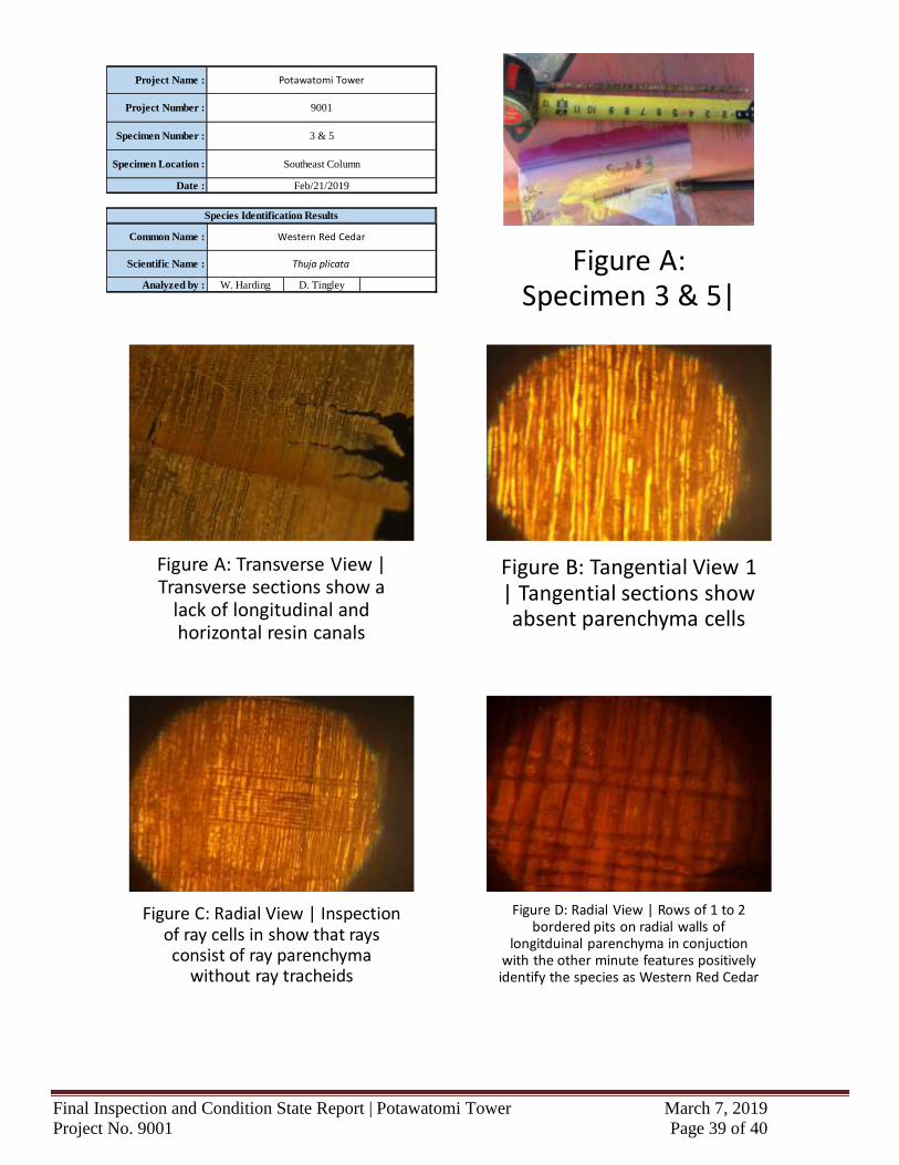
Specimen Location : Southeast Column
Potawatomi Tower
9001
3 & 5
Feb/21/2019
Common Name : Western Red Cedar
Figure C: Radial View | Inspection of ray cells in show that rays consist of ray parenchyma
without ray tracheids
Figure D: Radial View | Rows of 1 to 2 bordered pits on radial walls of
longitduinal parenchyma in conjuction with the other minute features positively identify the species as Western Red Cedar
Figure A: Transverse View | Transverse sections show a
lack of longitudinal and horizontal resin canals
Figure B: Tangential View 1 | Tangential sections show absent parenchyma cells
Figure A: Specimen 3 & 5|
Final Inspection and Condition State Report | Potawatomi Tower March 7, 2019
Project No. 9001 Page 40 of 40
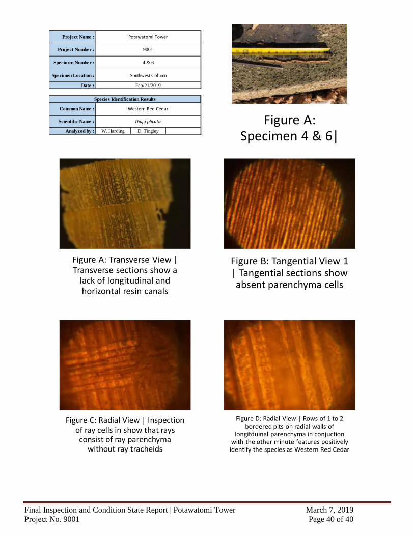
Date :
Analyzed by : W. Harding D. Tingley
Thuja plicataScientific Name :
Species Identification Results
Project Name :
Project Number :
Specimen Number :
Specimen Location : Southwest Column
Potawatomi Tower
9001
4 & 6
Feb/21/2019
Common Name : Western Red Cedar
Figure C: Radial View | Inspection of ray cells in show that rays consist of ray parenchyma
without ray tracheids
Figure D: Radial View | Rows of 1 to 2 bordered pits on radial walls of
longitduinal parenchyma in conjuction with the other minute features positively identify the species as Western Red Cedar
Figure A: Transverse View | Transverse sections show a
lack of longitudinal and horizontal resin canals
Figure B: Tangential View 1 | Tangential sections show absent parenchyma cells
Figure A: Specimen 4 & 6|