Embed Size (px)
Citation preview

Potential Future Applications & Topologies of Solid-State-Transformers (SSTs) J. W. Kolar & J. E. Huber Swiss Federal Institute of Technology (ETH) Zurich Power Electronic Systems Laboratory www.pes.ee.ethz.ch
Feb. 14, 2019

Outline
► SST Origins
▪ Traction ▪ Smart Grids
► Key Characteristics ► MEGATRENDS Future SST Application Areas
▪ Datacenter ▪ Smart Cities / Buildings ▪ High Power EV Charging ▪ More Electric/Hybrid Aircraft ▪ More Electric/Hybrid Ships ▪ Renewable Energy – Wind / Solar ▪ Deep Sea Exploration etc.
► Key Topologies ► Industry Demonstrators ► Conclusions
1/40
Th. Guillod G. Ortiz
Acknowledgement: D. Rothmund

Next Generation Traction Vehicles
SST Origins

► Classical Locomotives
- Catenary Voltage 15kV or 25kV - Frequency 162/3Hz or 50Hz - Power Level 1…10MW typ.
■ Transformer: Efficiency 90…95% (due to Restr. Vol., 99% typ. for Distr. Transf.) Current Density 6 A/mm2 (2A/mm2 typ. Distribution Transformer) Power Density 2…4 kg/kVA
!
Source: www.abb.com
2/61

► Passive Transformer
Pt …. Rated Power kW …. Window Utilization Factor Bmax ...Flux Density Amplitude Jrms… Winding Current Density f .…. Frequency
■ Low Frequency Large Weight / Volume ■ Trade-off Volume vs. Efficiency
● Magnetic Core Cross Section
● Winding Window
● Construction Volume
3/61
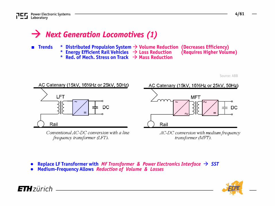
■ Trends * Distributed Propulsion System Volume Reduction (Decreases Efficiency) * Energy Efficient Rail Vehicles Loss Reduction (Requires Higher Volume) * Red. of Mech. Stress on Track Mass Reduction
● Replace LF Transformer with MF Transformer & Power Electronics Interface SST ● Medium-Frequency Allows Reduction of Volume & Losses
Source: ABB
4/61
Next Generation Locomotives (1)

■ Loss Distribution of Conventional & Next Generation Locomotives
LF MF
SST
● MF Provides Degree of Freedom Reduction of Volume & Losses (!)
5/61
Next Generation Locomotives (2)

Future Smart EE Distribution
Source: TU Munich
SST Motivation

► Advanced (High Power Quality) Grid Concept - Heinemann / ABB (2001)
● MV AC Distribution with DC Subsystems (LV and MV) and Distributed AC & DC Sources /Loads ● MF AC/AC Conv. with DC Link Coupled to Energy Storage provide High Power Qual. for Spec. Customers
►
►
►
►
►
►
6/61
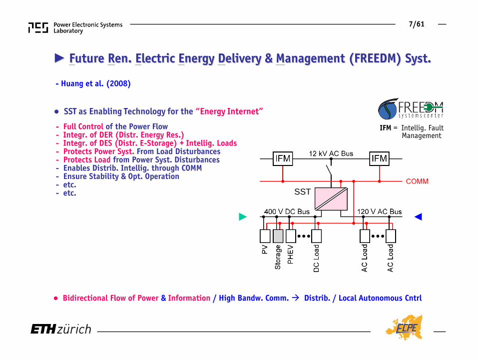
► Future Ren. Electric Energy Delivery & Management (FREEDM) Syst.
- Huang et al. (2008)
● SST as Enabling Technology for the “Energy Internet” - Full Control of the Power Flow - Integr. of DER (Distr. Energy Res.) - Integr. of DES (Distr. E-Storage) + Intellig. Loads - Protects Power Syst. From Load Disturbances - Protects Load from Power Syst. Disturbances - Enables Distrib. Intellig. through COMM - Ensure Stability & Opt. Operation - etc. - etc.
● Bidirectional Flow of Power & Information / High Bandw. Comm. Distrib. / Local Autonomous Cntrl
IFM = Intellig. Fault Management
►
►
!
SST
7/61
Source: www.yacht-chartercroatia.com

► AC vs. DC Power Systems ■ DC Voltage Ensures Max. Utiliz. of Isol. Voltage Highest Voltage RMS Value / Lowest Current (!) ■ Quadratic Dependency of Losses on Voltage Level Reduction of Conductor Cross Section
■ DC Voltage Level Transformation Requires Power Electronics Interfaces ■ DC Fault Current Clearing is Challenging (Missing Regular Current Zero Crossing)
Conductor Cross Sections
for Same Losses
8/61

► AC vs. DC Power Transmission
■ Low-Frequency AC (LFAC) as Possible (Purely Passive) Solution for Medium Transmission Distances
■ AC Cable – Thermal Limit Due to Cap. Current @ L = 0
■ HVDC Transmission – Advantageous for Long Distances Costs
Losses
Cable
Terminal
Distance
9/61

McMurray Electronic Transformer (1968) Brooks Solid-State Transformer (SST, 1980) EPRI Intelligent Universal Transformer (IUTTM) ABB Power Electronics Transformer (PET) Wang Energy Router etc.
► SST Key Characteristics
■ Interface to Medium-Voltage / Medium-Frequency Isolation / AC or DC Input and/or Output
10/61

● Lower Efficiency of SST Compared to “Grid-Type” Passive Transformer ● Medium Freq. Higher Transf. Efficiency only Partly Compensates Converter Stage Losses
LF Isolation Purely Passive (a)
Series Voltage Comp. (b) Series AC Chopper (c)
MF Isolation
Active Input & Output Stage (d)
LF
MF
11/61
Trade–Off - Controllability vs. Efficiency

► SST Development Cycles
■ Development Reaching Over Decades – Matched to “Product” Life Cycle
Traction
Grid
12/61

Global Megatrends
Digitalization Urbanization Sustainable Mobility Renewable Energy Etc.

Global Megatrends
Digitalization Urbanization Sustainable Mobility Renewable Energy Etc.

Server-Farms up to 450 MW
99.9999%/<30s/a $1.0 Mio./Shutdown
Since 2006
Running Costs > Initial Costs
─ Ranging from Medium Voltage to Power-Supplies-on-Chip ─ Short Power Supply Innovation Cycles ─ Modularity / Scalability ─ Higher Availability ─ Higher Efficiency ─ Higher Power Density ─ Lower Costs
Source: REUTERS/Sigtryggur Ari
► Deep Green / Zero Datacenters
13/61

■ 5…7% Reduction in Losses & Smaller Footprint ■ Improves Reliability & Power Quality
Future Modular SST-Based Power Distribution
─ Conventional
■ MV 48V 1.2V - Only 2 Conversion Stages from MV to CPU-Level (!)
Load
─ Direct 3-Φ 6.6kV AC 48V DC Conversion / Unidirectional SST
14/61

Global Megatrends
Digitalization Urbanization Sustainable Mobility Renewable Energy Etc.

► Urbanization ■ 60% of World Population Exp. to Live in Urban Cities by 2025 ■ 30 MEGA Cities Globally by 2023
─ Smart Buildings ─ Smart Mobility ─ Smart Energy / Grid ─ Smart ICT, etc.
► Selected Current & Future MEGA Cities 2015 2030
Source: World Urbanization Prospects: The 2014 Revision
15/61

Source:
Smart Cities / Grids / Buildings
www.masdar.ae
─ Masdar = “Source” ─ Fully Sustainable Energy Generation * Zero CO2 * Zero Waste ─ EV Transport / IPT Charging ─ to be finished 2025
16/61

Source:
www.masdar.ae
─ Masdar = “Source” ─ Fully Sustainable Energy Generation * Zero CO2 * Zero Waste ─ EV Transport / IPT Charging ─ to be finished 2025
Smart Cities / Grids / Buildings
17/61

DC Microgrids
─ Conventional ─ Future SST-Based Concept
■ Local DC Microgrid Integrating Loads/Ren. Sources/Storage ■ No Low-Voltage AC/DC Conversion Higher Efficiency & Lower Realization Effort
18/61
(!)

Global Megatrends
Digitalization Urbanization Sustainable Mobility Renewable Energy Etc.

► Sustainable Mobility
www.theicct.org
■ EU Mandatory 2020 CO2 Emission Targets for New Cars
─ 147g CO2/km for Light-Commercial Vehicles ─ 95g CO2/km for Passenger Cars ─ 100% Compliance in 2021
► Hybrid Vehicles ► Electric Vehicles
19/61
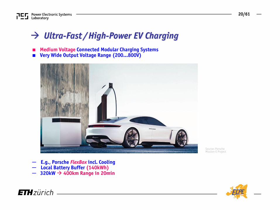
Ultra-Fast / High-Power EV Charging ■ Medium Voltage Connected Modular Charging Systems ■ Very Wide Output Voltage Range (200…800V)
Source: Porsche Mission-E Project
─ E.g., Porsche FlexBox incl. Cooling ─ Local Battery Buffer (140kWh) ─ 320kW 400km Range in 20min
20/61

21/61
Bidirectional SST-Based MV Interface ■ Conventional
■ Future SST-Based Concept
● On-Site Power / Energy Buffer „Energy-Hub“ ● Power / Energy Management Peak Load Shaving & Grid Support / Stabilization
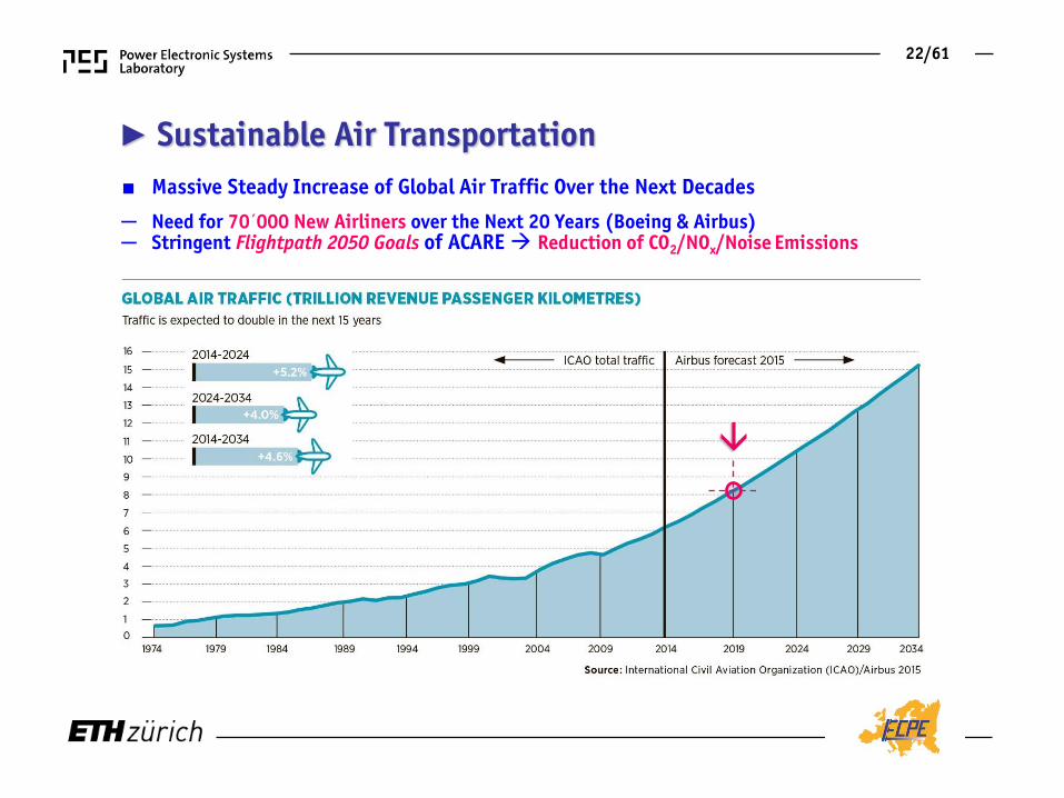
► Sustainable Air Transportation ■ Massive Steady Increase of Global Air Traffic Over the Next Decades
22/61
─ Need for 70´000 New Airliners over the Next 20 Years (Boeing & Airbus) ─ Stringent Flightpath 2050 Goals of ACARE Reduction of CO2/NOx/Noise Emissions

Source:
● Wing-Tip Mounted Eff. Optimized Gas Turbines & Distributed E-Fans (“E-Thrust”) ● MV or Superconducting Power Distribution Integr. 1000Wh/kg Batteries (EADS-Concept)
Turbo Generators
E-Fans / Continuous Nacelle
NASA N3-X Vehicle Concept
Future Distributed Propulsion Aircraft
■ Cut Emissions Until 2050
─ CO2 by 75%, ─ NOx by 90%, ─ Noise Level by 65%
23/61

● Generators ─ 2 x 40.2MW (NASA) ● E-Fans ─ 14 x 5.7 MW (1.3m Diameter)
► MV or Superconducting Power Distribution Integr. 1000Wh/kg Batteries (EADS-Concept)
Future Aircraft Electric Power System
24/61

► Sustainable Maritime Transportation ■ 80% of All Globally Traded Goods Transported by Ships
─ IMO Ship Energy Eff. Management Plan (SEEMP) & Energy Eff. Design Index (EEDI) ─ Crude Oil New Fuel Types (LNG) ─ Fully-Electric Port Infrastructure
► Worldwide Seaborne Trade in Billions of Cargo Ton-Miles
25/61
Source: UNCTAD 2018

Low-Voltage
Medium-Voltage Power Distribution
Low-Voltage
Medium-Voltage Power Distribution
■ Conv. AC Power Distrib. Network Disadvantage of Const. Prime Mover / Generator Speed
■ No Mech. Coupling of Propulsion & Prime Movers (DGs) Eff. Optim. Load Distrib. to the DGs ■ Energy Storage (Batt., Fuel Cell, etc.)
─ Peak Shaving ─ Opt. Gen. Scheduling ─ High Dyn. Performance
Hybrid Diesel-Electric Propulsion
26/61

Medium-Voltage Power Distribution
Low-Voltage
Medium-Voltage Power Distribution
Low-Voltage
Shipboard DC Power Distribution
■ 1kV/< 20MW or 1…35kV/20…100MW DC Distribution (Radial or Ring, Central. or Distrib.)
■ Future DC/AC-SST Interface to Low-Voltage AC & DC Grid ■ Future DC/DC-SST Interface to Energy Storage (ES)
27/61
─ DC Distribution Up to 20% Fuel Eff. Improvement / Smaller Footprint / Easier ES Integr.

Future Combat Ships (1) ■ MV Cellular DC Power Distribution on Future Combat Ships etc.
Source: General Dynamics
► “Energy Magazine” as Extension of Electric Power System / Individual Load Power Conditioning ► Bidirectional Power Flow for Advanced Weapon Load Demand ► Extreme Energy and Power Density Requirements
28/61
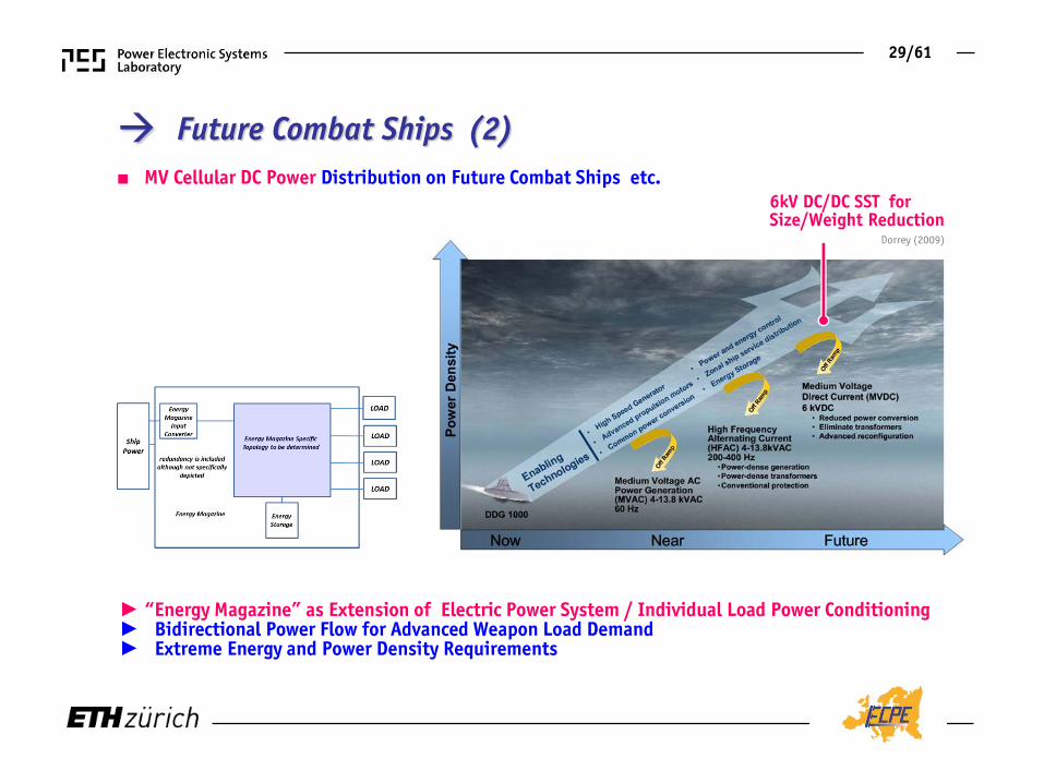
6kV DC/DC SST for Size/Weight Reduction
Dorrey (2009)
■ MV Cellular DC Power Distribution on Future Combat Ships etc.
► “Energy Magazine” as Extension of Electric Power System / Individual Load Power Conditioning ► Bidirectional Power Flow for Advanced Weapon Load Demand ► Extreme Energy and Power Density Requirements
29/61
Future Combat Ships (2)

Global Megatrends
Digitalization Urbanization Sustainable Mobility Renewable Energy Etc.

► Off-Shore Wind Farms
► Off-Shore Wind Farm
Source: M. Prahm / Flickr
30/61
■ Medium-Voltage Power Collection and Transmission

─ Current 690V Electrical System Significant Cabling Weight/Costs & Space Requirement ─ Future Local Medium-Frequency Conv. to Medium-Voltage AC or DC
► On-Shore Wind Power System
Wind Turbine Electrical System
► Future Off-Shore System
31/61
Low- Voltage Cable
Medium- Voltage Cable

Off-Shore Collector-Grid Concepts
■ DC/DC-SST Interface of Wind Turbine DC Link to MVDC Collector Grid Lower Losses (1%) & Volume ■ DC/DC-SST Interface of MVDC Grid to HVDC Transmission Lower Losses (1%) & Volume
■ Conventional AC Collector-Grid
32/61

Utility-Scale Solar Power Plants
■ Globally Installed PV Capacity Forecasted to 2.7 Terawatt by 2030 (IEA)
■ Medium-Voltage Power Collection and Transmission
33/61
Source: REUTERS/Stringer

Future DC Collector Grid
■ DC/DC SST for MPPT & Direct Interfacing of PV Strings to MV Collector Grid
■ 1.5% Efficiency Gain Compared to Conv. AC Technology
Conventional ►
AC Medium-Voltage
HV Mains HV Mains
High-Voltage Transmission
System
Medium-Voltage Collector Grid
Low-Voltage
Future ►
34/61

► Power-to-Gas ■ Electrolysis for Conversion of Excess Wind/Solar Electric Energy into Hydrogen Fuel-Cell Powered Cars Heating ■ High-Power @ Low DC Voltage (e.g. 220V) ■ Very Well Suited for MV-Connected SST-Based Power Supply ■ SST Allows Direct Interfacing to DC Collector Grid
– Hydrogenics 100 kW H2-Generator (η=57%)
35/61
Medium-Voltage Distribution System
Conventional ► Future
►

Global Megatrends
Digitalization Urbanization Sustainable Mobility Renewable Energy Etc.
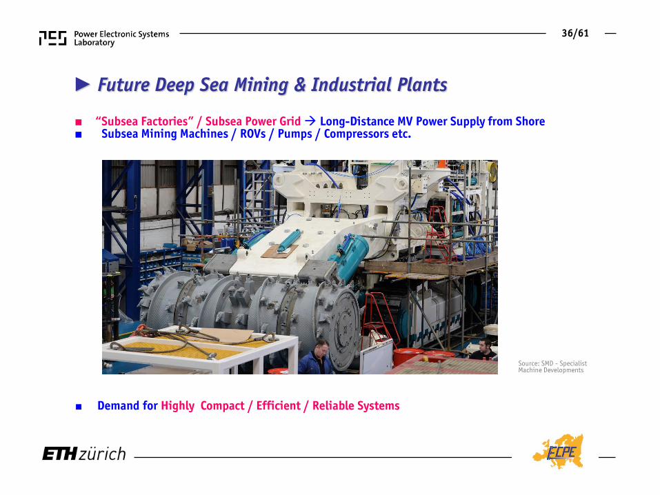
► Future Deep Sea Mining & Industrial Plants
■ “Subsea Factories” / Subsea Power Grid Long-Distance MV Power Supply from Shore ■ Subsea Mining Machines / ROVs / Pumps / Compressors etc.
36/61
■ Demand for Highly Compact / Efficient / Reliable Systems
Source: SMD - Specialist Machine Developments

Future Power Supply of Subsea Systems
Source: Devold (ABB 2012)
■ DC Transmission from Shore ■ No Platforms/Floaters
37/61
►
Today ► Future ► Ongoing ►

■ MV-Level Shore-Side Power to Docked Ships (“Cold-Ironing”) Diesel Aux. Engines Turned Off
Source: iecetech.org
Cutting Emissions & Noise in Airports / Harbours
■ Ground Power Supply of Aircraft APU Turned Off
■ SST Medium-Voltage Interfaces
─ Voltage Level / Frequ. Adaption ─ Low Space Requirement
38/61
SST Concept Implementation

Creation of MV LV
SST Topologies
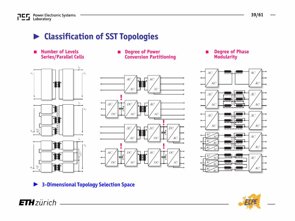
► Classification of SST Topologies
■ Degree of Power Conversion Partitioning
■ Number of Levels Series/Parallel Cells
■ Degree of Phase Modularity
► 3-Dimensional Topology Selection Space
!
!
! !
39/61

■ Very (!) Large Number of Possible Topologies – Partitioning of Power Conversion Matrix & DC-Link Topologies – Splitting of 3ph. System into Individual Phases Phase Modularity – Splitting of Medium Operating Voltage into Lower Partial Voltages Multi-Level/Cell Approaches
► Classification of SST Topologies
Degree of Power Conversion Partitioning
Degree of Phase Modularity
- Wrede (2003)
Number of Levels Series/Parallel Cells
40/61

Combining the Basic Concepts I
Single-Phase AC-DC Conversion /
Traction Applications

MV LF AC MF AC LV DC MV DC
Source: Zhao / Dujic ( ABB / 2011)
► Cascaded H-Bridges w. Isolated Back End ■ Multi-Cell Concept (AC/DC Front End & Soft-Switching Resonant DC//DC Converter) ■ Input Series / Output Parallel Connection – Self Symmetrizing (!) ■ Highly Modular / Scalable ■ Allows for Redundancy ■ High Power Demonstrators: etc.
41/61

► DCX - “DC Transformer”
■ fS ≈ Resonant Frequency “Unity Gain” (U2/U1=N2/N1) ■ Fixed Voltage Transfer Ratio Independent of Transferred Power (!) ■ Power Flow / Power Direction Self-Adjusting ■ No Controllability / No Need for Control ■ ZCS of All Devices
i1
i2 i1 i2
42/61

► Current Shaping & Isolation Isolation & Current Shaping
■ Isolated DC/DC Back End
■ Isolated AC/│AC│Front End
● Typical Multi-Cell SST Topology
● Two-Stage Multi-Cell Concept ● Direct Input Current Control ● Indirect Output Voltage Control ● High Complexity at MV Side
● Swiss SST (S3T)
● Two-Stage Multi-Cell Concept ● Indirect Input Current Control ● Direct Output Voltage Control ● Low Complexity on MV Side
43/61

► Modular Multilevel Converter
- Marquardt/Glinka (2003)
MV LF AC
MF AC
LV DC
Source: Zhao / Dujic ( ABB / 2011)
■ Single Transformer Isolation ■ Highly Modular / Scalable ■ Allows for Redundancy ■ Challenging Balancing on Cell DC Voltages
44/61

Combining the Basic Concepts II
Three-Phase AC-AC Conversion /
Smart Grid Applications
Source:

● 2-Level Inverter on LV Side ● HC-DCM-SRC DC//DC Conversion ● Cascaded H-Bridge MV Structure – ISOP Topology
► MEGALink @ ETH Zurich
SN = 630kVA ULV = 400 V UMV = 10kV
45/61

● 13.8kV 480V ● Scaled Prototype ● 15kV SiC-IGBTs, 1200V SiC MOSFETs
20kHz
22kV 800V
► Single-Cell Structure (SiC)
■ Redundancy Only for Series-Connection of Power Semiconductors (!)
46/61

SST Demonstrator Systems
Future Locomotives Smart Grid Applications

► 1ph. AC/DC Power Electronic Transformer - PET
P = 1.2MVA, 1.8MVA pk 9 Cells (Modular) 54 x (6.5kV, 400A IGBTs) 18 x (6.5kV, 200A IGBTs) 18 x (3.3kV, 800A IGBTs) 9 x MF Transf. (150kVA, 1.8kHz) 1 x Input Choke
- Dujic et al. (2011) - Heinemann (2002) - Steiner/Stemmler (1997) - Schibli/Rufer (1996)
47/61

► 1.2 MVA 1ph. AC/DC Power Electronic Transformer
■ Cascaded H-Bridges – 9 Cells ■ Resonant LLC DC/DC Converter Stages
48/61
■ Same Overall Volume as Conv. System ■ Future Development Targets Cutting Volume in Half

► 1.2 MVA 1ph. AC/DC Power Electronic Transformer
Efficiency
49/61
■ Cascaded H-Bridges – 9 Cells ■ Resonant LLC DC/DC Converter Stages
■ Same Overall Volume as Conv. System ■ Future Development Targets Cutting Volume in Half

► SiC-Enabled Solid-State Power Substation
- Das et al. (2011) - Lipo (2010) - Weiss (1985 for Traction Appl.)
50/61
● SiC Enabled 20kHz/1MVA “Solid State Power Substation” ● 97% Efficiency @ Full Load / 1/3rd Weight / 50% Volume Reduction (Comp. to 60Hz)
- Fully Phase Modular System - Indirect Matrix Converter Modules (f1 = f2) - MV ∆-Connection (13.8kVl-l, 4 Modules in Series) - LV Y-Connection (265V, Modules in Parallel)

51/61
- Das et al. (2011)
● SiC Enabled 20kHz/1MVA “Solid State Power Substation” ● 97% Efficiency @ Full Load / 1/3rd Weight / 50% Volume Reduction (Comp. to 60Hz)
- Fully Phase Modular System - Indirect Matrix Converter Modules (f1 = f2) - MV ∆-Connection (13.8kVl-l, 4 Modules in Series) - LV Y-Connection (265V, Modules in Parallel)
► SiC-Enabled Solid-State Power Substation

25kW SwiSS-Transformer @ ETH Zurich ■ Bidirectional 1-Φ 3.8 kVrms AC 400V DC Power Conversion ■ Based on 10kV SiC MOSFETs ■ Full Soft-Switching
► 35…75kHz iTCM Input Stage ► 48kHz DC-Transformer Output Stage
3.3 kW / dm3
3.8 kW / dm3
52/61

■ Full-Bridge iTCM – integrated Triang. Current Mode Operation Enables ZVS
► Full-Load Measurement (25kW @ 3.8kVrms AC, 7kV DC) - ZVS Over Full AC Cycle (!)
─ ZVS Requires Change of Sw. Current Direction in Each Sw. Period ─ Open-Loop Variation of Sw. Frequency for Const. ZVS Current (35…75kHz) ─ Separate Optim. of ZVS and Input Inductor Possible ─ No Large Ripple Input Current
► 3.8kV 7kV ZVS AC/DC Converter
3.3 kW / dm3
53/61
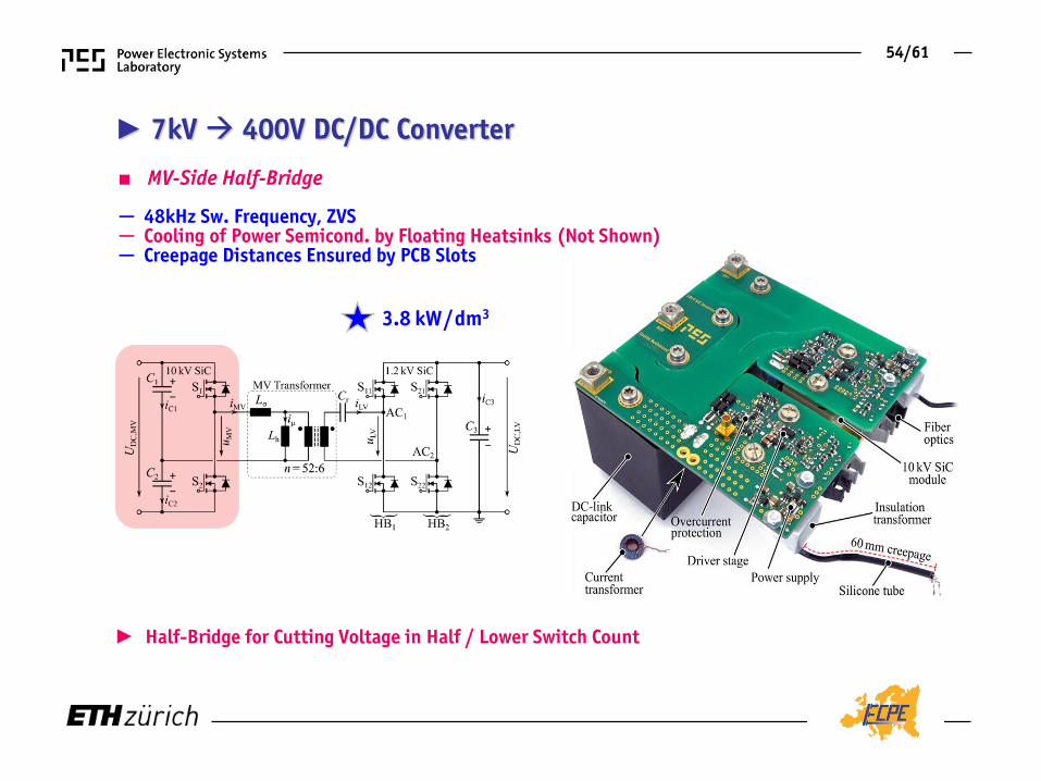
► 7kV 400V DC/DC Converter
■ MV-Side Half-Bridge
► Half-Bridge for Cutting Voltage in Half / Lower Switch Count
─ 48kHz Sw. Frequency, ZVS ─ Cooling of Power Semicond. by Floating Heatsinks (Not Shown) ─ Creepage Distances Ensured by PCB Slots
3.8 kW / dm3
54/61

■ MF-Transformer Measurement
► Transformer Prototype / Loss Distribution / Efficiency
─ Fully Tested @ 25kW / 7 kV ─ Calorimetric Loss Measurement ─ 99.64% Efficiency
► 7kV 400V DC/DC Converter
55/61

► Overall Performance
► Red. of Losses & Volume by Factor of > 2 Comp. to Alternative Approaches (!) ► Significantly Simpler Compared to Multi-Module SST Approach
■ Full Soft-Switching ■ 98.1% Overall Efficiency @ 25kW ■ 1.8 kW/dm3 (30W/in3)
56/61

1-Φ 2.4 kVrms AC 54V DC
► Power Density of 0.4 kW/dm3 (6.6W/in3) ► 96% Overall Efficiency @ 25kW
■ Published @ IEEE APEC 2017 ■ N=5 Series-Connected Cells @ MV-Side / Cost Optimum ■ Input Stage Module Boost PFC Half Contr. Thyr. Rect. / 1.2kV IGBTs & SiC Diodes ■ Output Stage Module 3-Level DC/DC Conv. - 600V SJ & 100V MOSFETs
57/61

Conclusions SST Limitations / Concepts
Research Areas

► The Solid-State Transformer Hype
Source:
■ Large # of Publications ! ■ Research on Main Application Challenges Currently Largely Missing
► Protection (?) ► Control in Active Grids (?) ► System Level Adv. (?)
58/61

► SST Applications The Road Ahead
● AC/AC
- Efficiency Challenge - More Eff. Voltage Control by * Tap Changers * Series Regulators (Partial Power) - Not Compatible w. Existing Infrastr. - Cost / Robustness / Reliability
■ Weight / Space Limited ■ Traction Applic. etc.
■ NOT (!) Weight / Space Limited ■ Smart Grid, Stationary Applications
59/61
● AC/DC
- Efficiency Challenge more Balanced - “Local” Applic. (Datacenters, DC Distr.) - Cost / Robustness / Reliability
● DC/DC
- No Other Option (!) - MV DC Collection Grids (Wind, PV) - Sw. Frequ. as DOF of Design
● DC/DC ● AC/DC ● AC/AC
- Sw. Frequ. as DOF of Design - Low Weight/Volume @ High Eff. - Local Applic. (Load/Source Integr.)
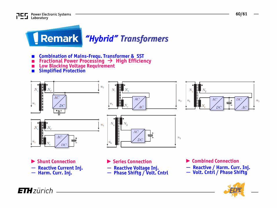
“Hybrid” Transformers
■ Combination of Mains-Frequ. Transformer & SST ■ Fractional Power Processing High Efficiency ■ Low Blocking Voltage Requirement ■ Simplified Protection
► Shunt Connection
─ Reactive Current Inj. ─ Harm. Curr. Inj.
► Series Connection
─ Reactive Voltage Inj. ─ Phase Shiftg / Volt. Cntrl
► Combined Connection
─ Reactive / Harm. Curr. Inj. ─ Volt. Cntrl / Phase Shiftg
60/61

Done !
To be Done…
■ Huge Multi-Disciplinary Challenges / Opportunities (!) are Still Ahead
► Current SST Research Status
61/61

Thank You!

Questions
www.pes.ee.ethz.ch/publications.html
Source: P. Aylward