Embed Size (px)
Citation preview
RTO-MP-SCI-145 24 - 1
UNCLASSIFIED/UNLIMITED
UNCLASSIFIED/UNLIMITED
Potential of Remote Laser Vibration Sensing for Military Applications
Peter Lutzmann, R. Frank, M. Hebel, R. Ebert Forschungsinstitut fuer Optronik und Mustererkennung (FGAN-FOM)
76275 Ettlingen, Gutleuthausstrasse 1, Germany phone: +49 7243 992140
ABSTRACT
Coherent laser radar based vibration detection of remote object allows to measure vibration features of objects due to the high Doppler resolution. In particular vibration imagery offers a large potential for short-range civil applications and for long-range target classification and identification including camouflaged or partly concealed targets. This technique allows also to discriminate between real targets and decoys. Non-contacting acousto-optic buried land mine detection shows the potential of this attractive technique at short range. Sample vibration images were taken by laser radars at λ = 10.6 µm (CO2 laser) and λ = 1.54 µm (erbium fiber laser) at ranges up to 3 km. Spatially unresolved targets were measured up to 40 km.
Keywords: vibrometry , vibration imagery, coherent laser radar
1.0 INTRODUCTION
For many years methods to classify and identify targets in the battlefield have been developed. There are passive methods, e.g. evaluation of the thermal image of a target, and active methods, e.g. analysis of the target radar echo. To prevent detection by a foe, passive or quasi passive procedures are preferred. Acoustic or seismographic methods are extremely sensitive to the propagation medium or additional battlefield effects and are therefore not very practical. Coherent laser radar is a method for measuring the vibration signature of the target offering the following advantages:
• comparatively covert (owing to small divergence and the short dwell time)
• high resolution (small wavelength)
• difficult to jam
• compatible with the current optical target detection sensors used on the battlefield
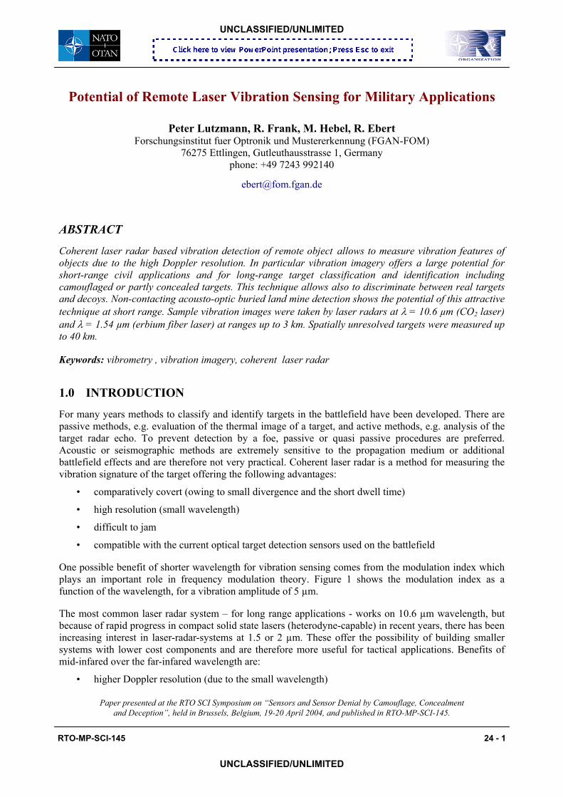
One possible benefit of shorter wavelength for vibration sensing comes from the modulation index which plays an important role in frequency modulation theory. Figure 1 shows the modulation index as a function of the wavelength, for a vibration amplitude of 5 µm.
The most common laser radar system – for long range applications - works on 10.6 µm wavelength, but because of rapid progress in compact solid state lasers (heterodyne-capable) in recent years, there has been increasing interest in laser-radar-systems at 1.5 or 2 µm. These offer the possibility of building smaller systems with lower cost components and are therefore more useful for tactical applications. Benefits of mid-infared over the far-infared wavelength are:
• higher Doppler resolution (due to the small wavelength)
Paper presented at the RTO SCI Symposium on “Sensors and Sensor Denial by Camouflage, Concealment and Deception”, held in Brussels, Belgium, 19-20 April 2004, and published in RTO-MP-SCI-145.
Potential of Remote Laser Vibration Sensing for Military Applications
24 - 2 RTO-MP-SCI-145
UNCLASSIFIED/UNLIMITED
UNCLASSIFIED/UNLIMITED
1000 THz 1000 THz
• higher detector sensivity (incoherent mode)
• no or less need of detector cooling
• higher laser cross section of targets
• use of conventional optical materials
In particular drawbacks with coherent detection (vibration sensing) are:
• stronger impact of the atmospheric turbulence
• higher quantum limited noise
For short range applications like testing automibile components and the Doppler based acoustic-to-seismic detection of buried mines, the HeNe laser wavelength λ = 632 nm is used very effectively.
Fig. 1: Modulation index as a function of the wavelength.
2.0 LONG RANGE APPLICATION
2.1 Comparison of range performances of 10.6 µm and 1.5 µm laser radar systems In order to discuss the range capability for the two wavelengths of λ=1.5 µm and λ=10.6 µm respectively, two generic laser radar systems are compared.
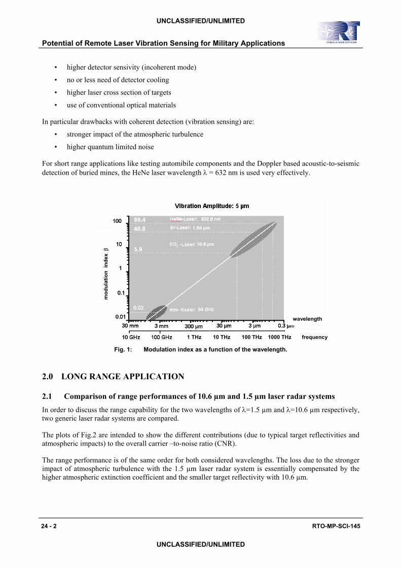
The plots of Fig.2 are intended to show the different contributions (due to typical target reflectivities and atmospheric impacts) to the overall carrier –to-noise ratio (CNR).
The range performance is of the same order for both considered wavelengths. The loss due to the stronger impact of atmospheric turbulence with the 1.5 µm laser radar system is essentially compensated by the higher atmospheric extinction coefficient and the smaller target reflectivity with 10.6 µm.
wavelength
frequency
mod
ulat
ion
inde
x β
1 THz 10 THz 100 THz 1000 THz
Potential of Remote Laser Vibration Sensing for Military Applications
RTO-MP-SCI-145 24 - 3
With common laser radar systems used over longer ranges, the laser beam is spread across most, if not all, parts of the target. This results in spatially unresolved target vibration signatures. Frequency distributions in the power spectra of such spatially unresolved vibration signatures are dependent on the area covered by the laser beam on target and on target aspect angle. Our aim was to investigate to what extent the target information content of the return signals would be increased by spatially resolving the vibration signature. Resolution may be achieved by using a scan device or a multi-element receiver. With such a 2-dimensional laser vibration sensing approach (vibration imagery) the target will be spatially resolved and one obtains a “data cube” consisting of a 2D map of vibration amplitudes across the target, one for each vibration frequency.
ideal Lambertian reflector + target reflectivity − − − + atmospheric extinction + atmospheric extinction and turbulence
1.5 µm laser radar system 10.6 µm laser radar system
ideal Lambertian reflector + target reflectivity − − − + atmospheric extinction + atmospheric extinction and turbulence
UNCLASSIFIED/UNLIMITED
UNCLASSIFIED/UNLIMITED
Fig. 2: Available carrier to noise ratio (solid line) assuming two generic systems with
wavelengths of λ=1.5 µm and λ=10.6 µm.
In summary, the main purpose of vibration imagery is to
• understand the principle governing vibration signature formation
• model spatially unresolved vibration signatures
• study the enhancement of target classification
• study the capability of classifying concealed targets.
Some examples of laser vibrometry techniques with and without spatial resolution capability will be shown.
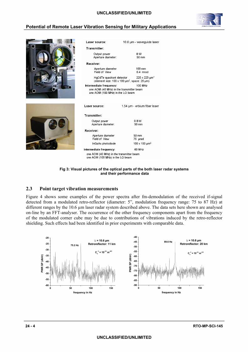
2.2 Experimental setup Both bistatic systems, the 10.6 µm–coherent laser radar (BASIS 2 of FGAN-FOM) as well the 1.5 µm-coherent laser radar (SAVIS of FGAN-FOM) were built up at our institute and were used for the long range experiments. Visible pictures of the optical parts of the both laser radar systems and the most important performance data are given in Fig.: 3.
Potential of Remote Laser Vibration Sensing for Military Applications
24 - 4 RTO-MP-SCI-145
Fig 3: Visual pictures of the optical parts of the both laser radar systems and their performance data
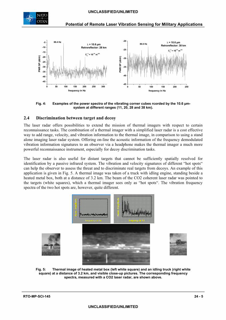
2.3 Point target vibration measurements Figure 4 shows some examples of the power spectra after fm-demodulation of the received if-signal detected from a modulated retro-reflector (diameter: 5”, modulation frequency range: 75 to 87 Hz) at different ranges by the 10.6 µm laser radar system described above. The data sets here shown are analysed on-line by an FFT-analyser. The occurrence of the other frequency components apart from the frequency of the modulated corner cube may be due to contributions of vibrations induced by the retro-reflector shielding. Such effects had been identified in prior experiments with comparable data.
0 50 100 150-60
-55
-50
-45
-40
-35
-30
-25
-20
Cn2 = 10-14 m-2/3
75.2 Hz
λ = 10.6 µmRetroreflector: 11 km
PWR
SP
(dbV
r)
frequency in Hz
0 50 100 150-90
-85
-80
-75
-70
-65
-60
-55
-50
-45
-40
Cn2 = 10-14 m-2/3
89.6 Hz λ = 10.6 µmRetroreflector: 20 km
PWR
SP
(dbV
r)
frequency in Hz
UNCLASSIFIED/UNLIMITED
UNCLASSIFIED/UNLIMITED
0 50 100 150 200 250 300
-45
-40
-35
-30
-25
-20
-15
-10
-5
Cn2 = 10-14 m-2/3
88.4 Hzλ = 10.6 µm
Retroreflector: 28 km
PWR
SP (d
bVr)
frequency in Hz
0 50 100 150 200 250-45
-40
-35
-30
-25
-20
Cn2 = 10-14 m-2/3
86.6 Hz λ = 10.6 µmRetroreflector: 38 km
PWR
SP (d
bVr)
frequency in Hz
Fig. 4: Examples of the power spectra of the vibrating corner cubes rcorded by the 10.6 µm-system at different ranges (11, 20, 28 and 38 km).
2.4 Discrimination between target and decoy The laser radar offers possibilities to extend the mission of thermal imagers with respect to certain reconnaissance tasks. The combination of a thermal imager with a simplified laser radar is a cost effective way to add range, velocity, and vibration information to the thermal image, in comparison to using a stand alone imaging laser radar system. Offering on-line the acoustic information of the frequency demodulated vibration information signatures to an observer via a headphone makes the thermal imager a much more powerful reconnaissance instrument, especially for decoy discrimination tasks.
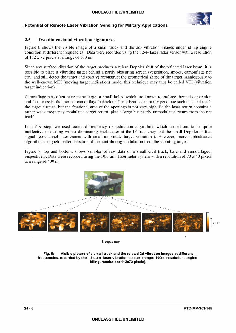
The laser radar is also useful for distant targets that cannot be sufficiently spatially resolved for identification by a passive infrared system. The vibration and velocity signatures of different “hot spots“ can help the observer to assess the threat and to discriminate real targets from decoys. An example of this application is given in Fig. 5. A thermal image was taken of a truck with idling engine, standing beside a heated metal box, both at a distance of 3.2 km. The beam of the CO2 coherent laser radar was pointed to the targets (white squares), which a thermal imager sees only as “hot spots“. The vibration frequency spectra of the two hot spots are, however, quite different.
Fig. 5: Thermal image of heated metal box (left white square) and an idling truck (right white square) at a distance of 3.2 km, and visible close-up pictures. The corresponding frequency
spectra, measured with a CO2 laser radar, are shown above.
RTO-MP-SCI-145 24 - 5
UNCLASSIFIED/UNLIMITED
UNCLASSIFIED/UNLIMITED
Potential of Remote Laser Vibration Sensing for Military Applications
Potential of Remote Laser Vibration Sensing for Military Applications
24 - 6 RTO-MP-SCI-145
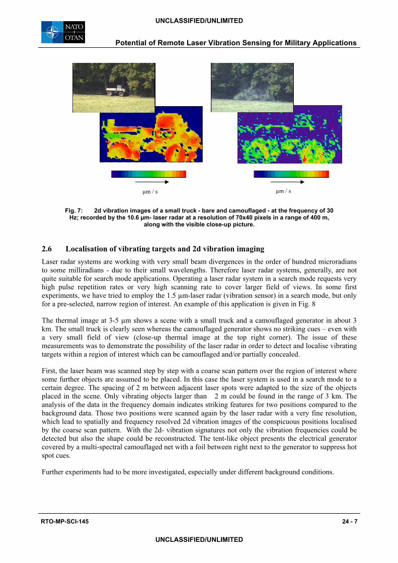
2.5 Two dimensional vibration signatures Figure 6 shows the visible image of a small truck and the 2d- vibration images under idling engine condition at different frequencies. Data were recorded using the 1.54- laser radar sensor with a resolution of 112 x 72 pixels at a range of 100 m.
Since any surface vibration of the target produces a micro Doppler shift of the reflected laser beam, it is possible to place a vibrating target behind a partly obscuring screen (vegetation, smoke, camouflage net etc.) and still detect the target and (partly) reconstruct the geometrical shape of the target. Analogously to the well-known MTI (moving target indication) mode, this technique may thus be called VTI (vibration target indication).
Camouflage nets often have many large or small holes, which are known to enforce thermal convection and thus to assist the thermal camouflage behaviour. Laser beams can partly penetrate such nets and reach the target surface, but the fractional area of the openings is not very high. So the laser return contains a rather weak frequency modulated target return, plus a large but nearly unmodulated return from the net itself.
In a first step, we used standard frequency demodulation algorithms which turned out to be quite ineffective in dealing with a dominating backscatter at the IF frequency and the small Doppler-shifted signal (co-channel interference with small-amplitude target vibrations). However, more sophisticated algorithms can yield better detection of the contributing modulation from the vibrating target.
Figure 7, top and bottom, shows samples of raw data of a small civil truck, bare and camouflaged, respectively. Data were recorded using the 10.6 µm- laser radar system with a resolution of 70 x 40 pixels at a range of 400 m.
Fig. 6: Visible picture of a small truck and the related 2d vibration images at different frequencies, recorded by the 1.54 µm- laser vibration sensor (range: 100m, resolution, engine:
idling, resolution: 112x72 pixels).
UNCLASSIFIED/UNLIMITED
UNCLASSIFIED/UNLIMITED
µm / s µm / s
Fig. 7: 2d vibration images of a small truck - bare and camouflaged - at the frequency of 30 Hz; recorded by the 10.6 µm- laser radar at a resolution of 70x40 pixels in a range of 400 m,
along with the visible close-up picture.
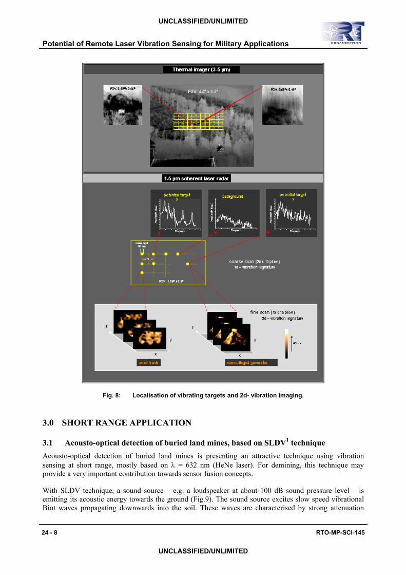
2.6 Localisation of vibrating targets and 2d vibration imaging Laser radar systems are working with very small beam divergences in the order of hundred microradians to some milliradians - due to their small wavelengths. Therefore laser radar systems, generally, are not quite suitable for search mode applications. Operating a laser radar system in a search mode requests very high pulse repetition rates or very high scanning rate to cover larger field of views. In some first experiments, we have tried to employ the 1.5 µm-laser radar (vibration sensor) in a search mode, but only for a pre-selected, narrow region of interest. An example of this application is given in Fig. 8
The thermal image at 3-5 µm shows a scene with a small truck and a camouflaged generator in about 3 km. The small truck is clearly seen whereas the camouflaged generator shows no striking cues – even with a very small field of view (close-up thermal image at the top right corner). The issue of these measurements was to demonstrate the possibility of the laser radar in order to detect and localise vibrating targets within a region of interest which can be camouflaged and/or partially concealed.
First, the laser beam was scanned step by step with a coarse scan pattern over the region of interest where some further objects are assumed to be placed. In this case the laser system is used in a search mode to a certain degree. The spacing of 2 m between adjacent laser spots were adapted to the size of the objects placed in the scene. Only vibrating objects larger than 2 m could be found in the range of 3 km. The analysis of the data in the frequency domain indicates striking features for two positions compared to the background data. Those two positions were scanned again by the laser radar with a very fine resolution, which lead to spatially and frequency resolved 2d vibration images of the conspicuous positions localised by the coarse scan pattern. With the 2d- vibration signatures not only the vibration frequencies could be detected but also the shape could be reconstructed. The tent-like object presents the electrical generator covered by a multi-spectral camouflaged net with a foil between right next to the generator to suppress hot spot cues.
Further experiments had to be more investigated, especially under different background conditions.
RTO-MP-SCI-145 24 - 7
UNCLASSIFIED/UNLIMITED
UNCLASSIFIED/UNLIMITED
Potential of Remote Laser Vibration Sensing for Military Applications
Potential of Remote Laser Vibration Sensing for Military Applications
24 - 8 RTO-MP-SCI-145
UNCLASSIFIED/UNLIMITED
UNCLASSIFIED/UNLIMITED
Fig. 8: Localisation of vibrating targets and 2d- vibration imaging.
3.0 SHORT RANGE APPLICATION
3.1 Acousto-optical detection of buried land mines, based on SLDV1 technique Acousto-optical detection of buried land mines is presenting an attractive technique using vibration sensing at short range, mostly based on λ = 632 nm (HeNe laser). For demining, this technique may provide a very important contribution towards sensor fusion concepts.
With SLDV technique, a sound source – e.g. a loudspeaker at about 100 dB sound pressure level – is emitting its acoustic energy towards the ground (Fig.9). The sound source excites slow speed vibrational Biot waves propagating downwards into the soil. These waves are characterised by strong attenuation
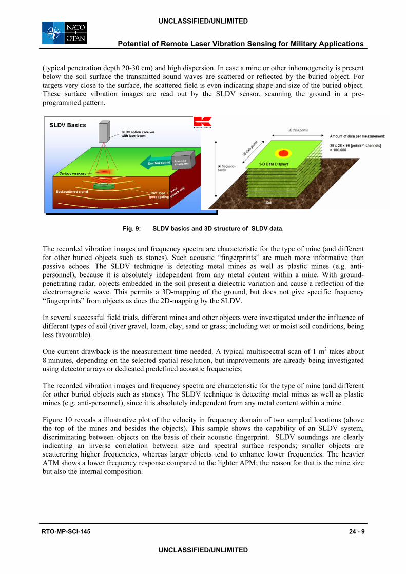
(typical penetration depth 20-30 cm) and high dispersion. In case a mine or other inhomogeneity is present below the soil surface the transmitted sound waves are scattered or reflected by the buried object. For targets very close to the surface, the scattered field is even indicating shape and size of the buried object. These surface vibration images are read out by the SLDV sensor, scanning the ground in a pre-programmed pattern.
Fig. 9: SLDV basics and 3D structure of SLDV data.
The recorded vibration images and frequency spectra are characteristic for the type of mine (and different for other buried objects such as stones). Such acoustic “fingerprints” are much more informative than passive echoes. The SLDV technique is detecting metal mines as well as plastic mines (e.g. anti-personnel), because it is absolutely independent from any metal content within a mine. With ground-penetrating radar, objects embedded in the soil present a dielectric variation and cause a reflection of the electromagnetic wave. This permits a 3D-mapping of the ground, but does not give specific frequency “fingerprints” from objects as does the 2D-mapping by the SLDV.
In several successful field trials, different mines and other objects were investigated under the influence of different types of soil (river gravel, loam, clay, sand or grass; including wet or moist soil conditions, being less favourable).
One current drawback is the measurement time needed. A typical multispectral scan of 1 m2 takes about 8 minutes, depending on the selected spatial resolution, but improvements are already being investigated using detector arrays or dedicated predefined acoustic frequencies.
The recorded vibration images and frequency spectra are characteristic for the type of mine (and different for other buried objects such as stones). The SLDV technique is detecting metal mines as well as plastic mines (e.g. anti-personnel), since it is absolutely independent from any metal content within a mine.
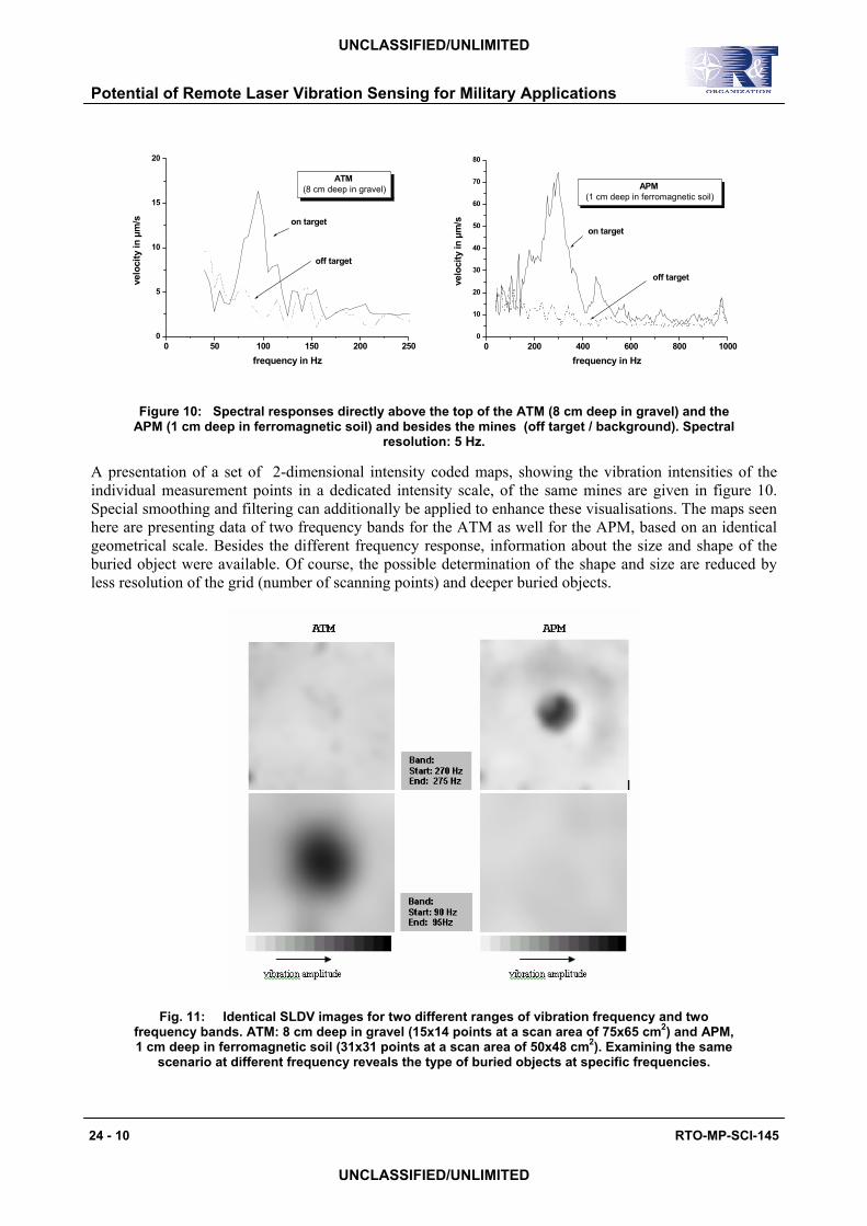
Figure 10 reveals a illustrative plot of the velocity in frequency domain of two sampled locations (above the top of the mines and besides the objects). This sample shows the capability of an SLDV system, discriminating between objects on the basis of their acoustic fingerprint. SLDV soundings are clearly indicating an inverse correlation between size and spectral surface responds; smaller objects are scatterering higher frequencies, whereas larger objects tend to enhance lower frequencies. The heavier ATM shows a lower frequency response compared to the lighter APM; the reason for that is the mine size but also the internal composition.
RTO-MP-SCI-145 24 - 9
UNCLASSIFIED/UNLIMITED
UNCLASSIFIED/UNLIMITED
Potential of Remote Laser Vibration Sensing for Military Applications
0 50 100 150 200 2500
5
10
15
20
off target
on target
ATM (8 cm deep in gravel)
velo
city
in µ
m/s
frequency in Hz0 200 400 600 800 1000
0
10
20
30
40
50
60
70
80
off target
on target
APM (1 cm deep in ferromagnetic soil)
velo
city
in µ
m/s
frequency in Hz
Figure 10: Spectral responses directly above the top of the ATM (8 cm deep in gravel) and the APM (1 cm deep in ferromagnetic soil) and besides the mines (off target / background). Spectral
resolution: 5 Hz.
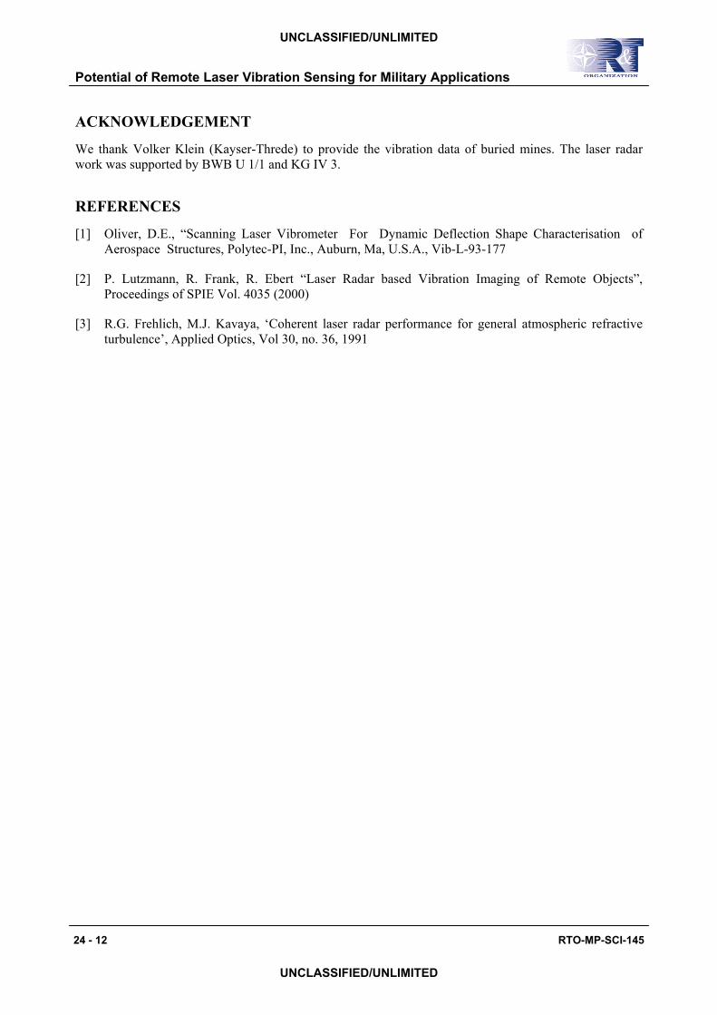
A presentation of a set of 2-dimensional intensity coded maps, showing the vibration intensities of the individual measurement points in a dedicated intensity scale, of the same mines are given in figure 10. Special smoothing and filtering can additionally be applied to enhance these visualisations. The maps seen here are presenting data of two frequency bands for the ATM as well for the APM, based on an identical geometrical scale. Besides the different frequency response, information about the size and shape of the buried object were available. Of course, the possible determination of the shape and size are reduced by less resolution of the grid (number of scanning points) and deeper buried objects.
Fig. 11: Identical SLDV images for two different ranges of vibration frequency and two frequency bands. ATM: 8 cm deep in gravel (15x14 points at a scan area of 75x65 cm2) and APM, 1 cm deep in ferromagnetic soil (31x31 points at a scan area of 50x48 cm2). Examining the same
scenario at different frequency reveals the type of buried objects at specific frequencies.
24 - 10 RTO-MP-SCI-145
UNCLASSIFIED/UNLIMITED
UNCLASSIFIED/UNLIMITED
Potential of Remote Laser Vibration Sensing for Military Applications

Potential of Remote Laser Vibration Sensing for Military Applications
RTO-MP-SCI-145 24 - 11
UNCLASSIFIED/UNLIMITED
UNCLASSIFIED/UNLIMITED
4.0 DATA PROCESSING AND ANALYSING
The data processing and analyzing were developed for the mine detection and classification. This technique will be also used to investigate the classification of vibrationg land vehicles (stationary and/or driving). Fig. 12 shows the hierarchical data processing scheme ranging from the preprocessing, segmentation using a multi-threshold algorithm for the segmentation of cues and reduce false alarms by analyzing the stability of object size, contrast and shape in the frequency domain, feature extraction and classification.
Fig. 12: The hierarchical data processing scheme for classifying buried mines and land vehicles.
5.0 SUMMARY
We have demonstrated the large potential of vibration imaging, giving some examples of spatially unresolved and resolved vibration signatures, as a tool for analysing the vibration behaviour of remote objects. For the future, we plan to introduce several improvements, especially in the area of processing algorithms and by reducing the time needed to record such vibration images (2-dimensional detector arraya for the receiver).
Potential of Remote Laser Vibration Sensing for Military Applications
24 - 12 RTO-MP-SCI-145
UNCLASSIFIED/UNLIMITED
UNCLASSIFIED/UNLIMITED
ACKNOWLEDGEMENT
We thank Volker Klein (Kayser-Threde) to provide the vibration data of buried mines. The laser radar work was supported by BWB U 1/1 and KG IV 3.
REFERENCES
[1] Oliver, D.E., “Scanning Laser Vibrometer For Dynamic Deflection Shape Characterisation of Aerospace Structures, Polytec-PI, Inc., Auburn, Ma, U.S.A., Vib-L-93-177
[2] P. Lutzmann, R. Frank, R. Ebert “Laser Radar based Vibration Imaging of Remote Objects”, Proceedings of SPIE Vol. 4035 (2000)
[3] R.G. Frehlich, M.J. Kavaya, ‘Coherent laser radar performance for general atmospheric refractive turbulence’, Applied Optics, Vol 30, no. 36, 1991


![MECHANICAL VIBRATION SENSING FOR STRUCTURAL HEALTH ... · Structural health monitoring based on vibration measurements has a long tradition [1]. In these applications the mechanical](https://img.pdfslide.net/doc/110x75/5e6f1c710abee12a476fe6c6/mechanical-vibration-sensing-for-structural-health-structural-health-monitoring.jpg)