Embed Size (px)
Citation preview
7/29/2019 Power Amplifiers Chap22
http://slidepdf.com/reader/full/power-amplifiers-chap22 1/29
Storey: Electrical & Electronic Systems © Pearson Education Limited 2004 OHT 22.‹#›
Power Electronics
Introduction
Bipolar Transistor Power Amplifiers
Classes of Amplifier
Four-layer Devices
Power Supplies and Voltage Regulators
Chapter 22
7/29/2019 Power Amplifiers Chap22
http://slidepdf.com/reader/full/power-amplifiers-chap22 2/29
Storey: Electrical & Electronic Systems © Pearson Education Limited 2004 OHT 22.‹#›
Introduction
Amplifiers that produce voltage amplification or
current amplification also produce power
amplification
However, the term power amplifier is normally
reserved for circuits whose main function is to deliver
large amounts of power
These can be produced using FETs or bipolar transistors, or using special purpose devices such as
thyristors and triacs
22.1
7/29/2019 Power Amplifiers Chap22
http://slidepdf.com/reader/full/power-amplifiers-chap22 3/29
Storey: Electrical & Electronic Systems © Pearson Education Limited 2004 OHT 22.‹#›
Bipolar Transistor Power Amplifiers
When designing a power amplifier we normally
require a low output resistance so that the circuit can
deliver a high output current
– we often use an emitter-follower
– this does not produce voltage gain but has a low
output resistance
– in many cases the load applied to a power amplifier isnot simply resistive but also has an inductive or
capacitive element
22.2
7/29/2019 Power Amplifiers Chap22
http://slidepdf.com/reader/full/power-amplifiers-chap22 4/29
Storey: Electrical & Electronic Systems © Pearson Education Limited 2004 OHT 22.‹#›
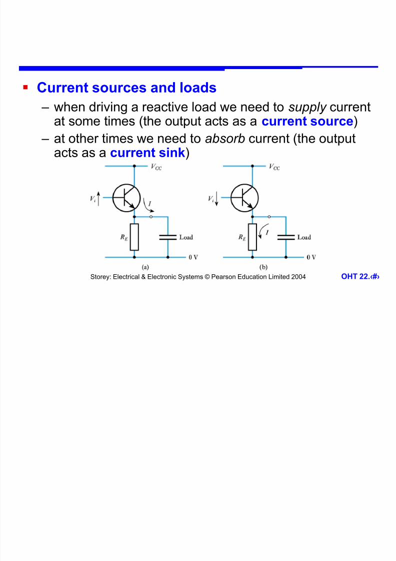
Current sources and loads
– when driving a reactive load we need to supply currentat some times (the output acts as a current source)
– at other times we need to absorb current (the outputacts as a current sink)

7/29/2019 Power Amplifiers Chap22
http://slidepdf.com/reader/full/power-amplifiers-chap22 5/29
Storey: Electrical & Electronic Systems © Pearson Education Limited 2004 OHT 22.‹#›
– the circuit above is a good current source but a poor
current sink (stored charge must be removed by R E )
– an alternative circuit using pnp transistors (below) is a
good current sink but a poor current source

7/29/2019 Power Amplifiers Chap22
http://slidepdf.com/reader/full/power-amplifiers-chap22 6/29
Storey: Electrical & Electronic Systems © Pearson Education Limited 2004 OHT 22.‹#›
Push-pull amplifiers
– combining these
circuits can produce
an arrangement thatis both a good current
source and a good
current sink
– this is termed apush-pull amplifier

7/29/2019 Power Amplifiers Chap22
http://slidepdf.com/reader/full/power-amplifiers-chap22 7/29
Storey: Electrical & Electronic Systems © Pearson Education Limited 2004 OHT 22.‹#›
Driving a push-pull stage

7/29/2019 Power Amplifiers Chap22
http://slidepdf.com/reader/full/power-amplifiers-chap22 8/29
Storey: Electrical & Electronic Systems © Pearson Education Limited 2004 OHT 22.‹#›
Distortion in push-pull amplifiers

7/29/2019 Power Amplifiers Chap22
http://slidepdf.com/reader/full/power-amplifiers-chap22 9/29
Storey: Electrical & Electronic Systems © Pearson Education Limited 2004 OHT 22.‹#›
Improved push-pull output stage arrangements

7/29/2019 Power Amplifiers Chap22
http://slidepdf.com/reader/full/power-amplifiers-chap22 10/29
Storey: Electrical & Electronic Systems © Pearson Education Limited 2004 OHT 22.‹#›
Amplifier efficiency
– an important consideration in the design of power
amplifiers is efficiency
– efficiency determines the power dissipated in the
amplifier itself
– power dissipation is important because it determines
the amount of waste heat produced
excess heat may require heat sinks, cooling fans, etc.
supplythefromabsorbedpower
loadtheindissipatedpower Efficiency

7/29/2019 Power Amplifiers Chap22
http://slidepdf.com/reader/full/power-amplifiers-chap22 11/29
Storey: Electrical & Electronic Systems © Pearson Education Limited 2004 OHT 22.‹#›
Classes of Amplifier
Class A
– active device conducts for complete cycle of input signal
– example shown here
– poor efficiency
(normally less
than 25%)
– low distortion
22.3
7/29/2019 Power Amplifiers Chap22
http://slidepdf.com/reader/full/power-amplifiers-chap22 12/29
Storey: Electrical & Electronic Systems © Pearson Education Limited 2004 OHT 22.‹#›
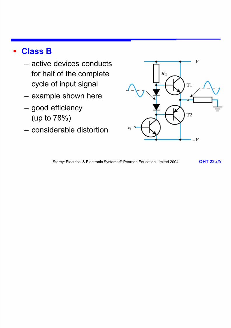
Class B
– active devices conducts
for half of the complete
cycle of input signal
– example shown here
– good efficiency
(up to 78%) – considerable distortion
7/29/2019 Power Amplifiers Chap22
http://slidepdf.com/reader/full/power-amplifiers-chap22 13/29
Storey: Electrical & Electronic Systems © Pearson Education Limited 2004 OHT 22.‹#›
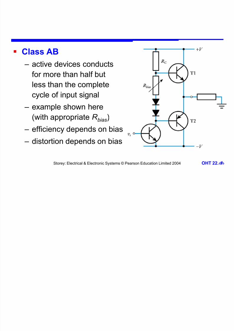
Class AB
– active devices conducts
for more than half but
less than the complete
cycle of input signal
– example shown here
(with appropriate R bias)
– efficiency depends on bias
– distortion depends on bias

7/29/2019 Power Amplifiers Chap22
http://slidepdf.com/reader/full/power-amplifiers-chap22 14/29
Storey: Electrical & Electronic Systems © Pearson Education Limited 2004 OHT 22.‹#›
Class C
– active devices conducts
for less than half the
complete cycle of
input signal
– example shown here
–high efficiency(approaching 100%)
– gross distortion

7/29/2019 Power Amplifiers Chap22
http://slidepdf.com/reader/full/power-amplifiers-chap22 15/29
Storey: Electrical & Electronic Systems © Pearson Education Limited 2004 OHT 22.‹#›
Class D
– in class D amplifiers the active devices are switches
and are either ON or OFF
– an ideal switch would dissipate no power
since either the current or the voltage is zero
– even real devices make good switches
– amplifiers of this type are called switching amplifiers or switch-mode amplifiers
– efficiency is very high

7/29/2019 Power Amplifiers Chap22
http://slidepdf.com/reader/full/power-amplifiers-chap22 16/29
Storey: Electrical & Electronic Systems © Pearson Education Limited 2004 OHT 22.‹#›
Four-layer Devices
Although transistors make excellent switches, they
have limitations when it comes to switching high
currents at high voltages
In such situations we often use devices that are
specifically designed for such applications
These are four-layer devices
– these are not transistors, but have a great deal incommon with bipolar transistors
22.4

7/29/2019 Power Amplifiers Chap22
http://slidepdf.com/reader/full/power-amplifiers-chap22 17/29
Storey: Electrical & Electronic Systems © Pearson Education Limited 2004 OHT 22.‹#›
The thyristor
– a four-layer
device with a
pnpn structure – three terminals:
anode, cathode
and gate
– gate is thecontrol input
7/29/2019 Power Amplifiers Chap22
http://slidepdf.com/reader/full/power-amplifiers-chap22 18/29
Storey: Electrical & Electronic Systems © Pearson Education Limited 2004 OHT 22.‹#›
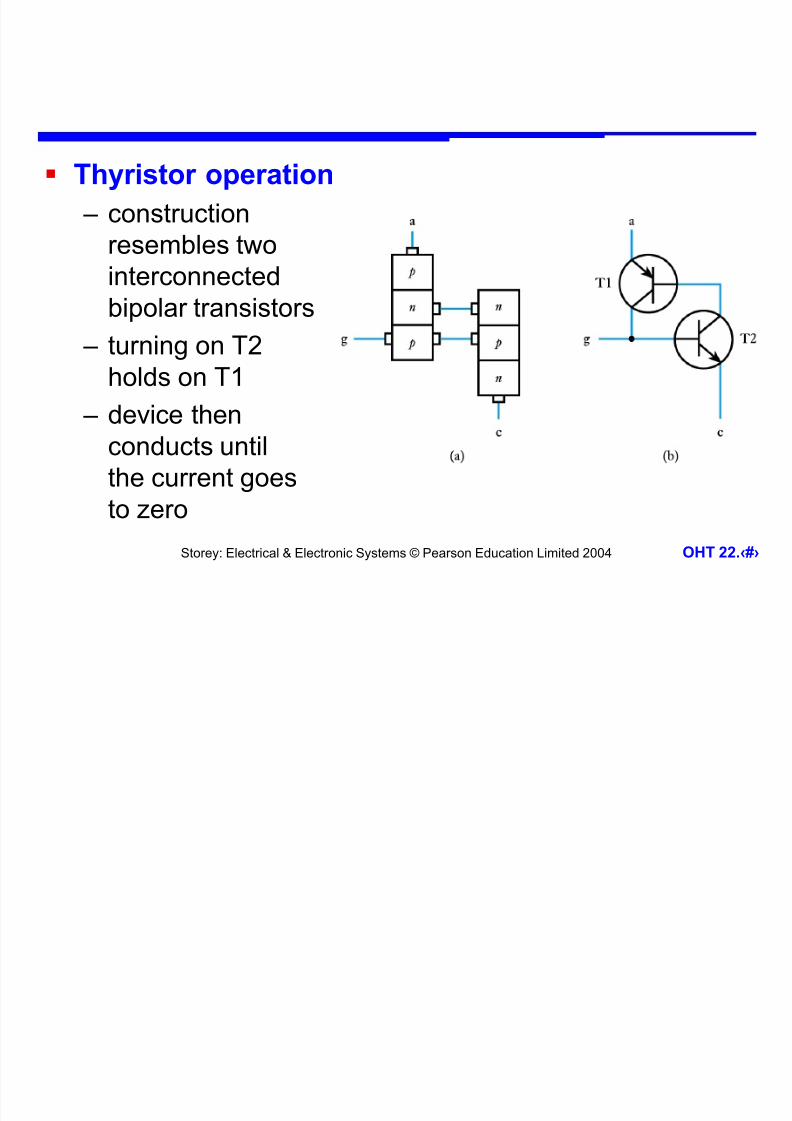
Thyristor operation
– construction
resembles two
interconnectedbipolar transistors
– turning on T2
holds on T1
– device thenconducts until
the current goes
to zero

7/29/2019 Power Amplifiers Chap22
http://slidepdf.com/reader/full/power-amplifiers-chap22 19/29
Storey: Electrical & Electronic Systems © Pearson Education Limited 2004 OHT 22.‹#›
Use of a thyristor in
AC power control
– once triggered the device
conducts for the remainder of the half cycle
– varying firing time
determines output power
– allows control from 0-50%of full power

7/29/2019 Power Amplifiers Chap22
http://slidepdf.com/reader/full/power-amplifiers-chap22 20/29
Storey: Electrical & Electronic Systems © Pearson Education Limited 2004 OHT 22.‹#›
Full-wave power control using thyristors
– full-wave control
required two devices – allows control from
0-100% of full power
– requires two gatedrive circuits
– opto-isolation oftenused to insulatecircuits from AC supply

7/29/2019 Power Amplifiers Chap22
http://slidepdf.com/reader/full/power-amplifiers-chap22 21/29
Storey: Electrical & Electronic Systems © Pearson Education Limited 2004 OHT 22.‹#›
The triac
– resembles a bidirectionalthyristor
–allows full-wave controlusing a single device
– often used with abidirectional trigger diode (a diac) to produce
the necessary drive pulses – this breaks down at a
particular voltage and fires the triac

7/29/2019 Power Amplifiers Chap22
http://slidepdf.com/reader/full/power-amplifiers-chap22 22/29
Storey: Electrical & Electronic Systems © Pearson Education Limited 2004 OHT 22.‹#›
A simple lamp-dimmer using a triac
7/29/2019 Power Amplifiers Chap22
http://slidepdf.com/reader/full/power-amplifiers-chap22 23/29
Storey: Electrical & Electronic Systems © Pearson Education Limited 2004 OHT 22.‹#›
Power Supplies and Voltage Regulators
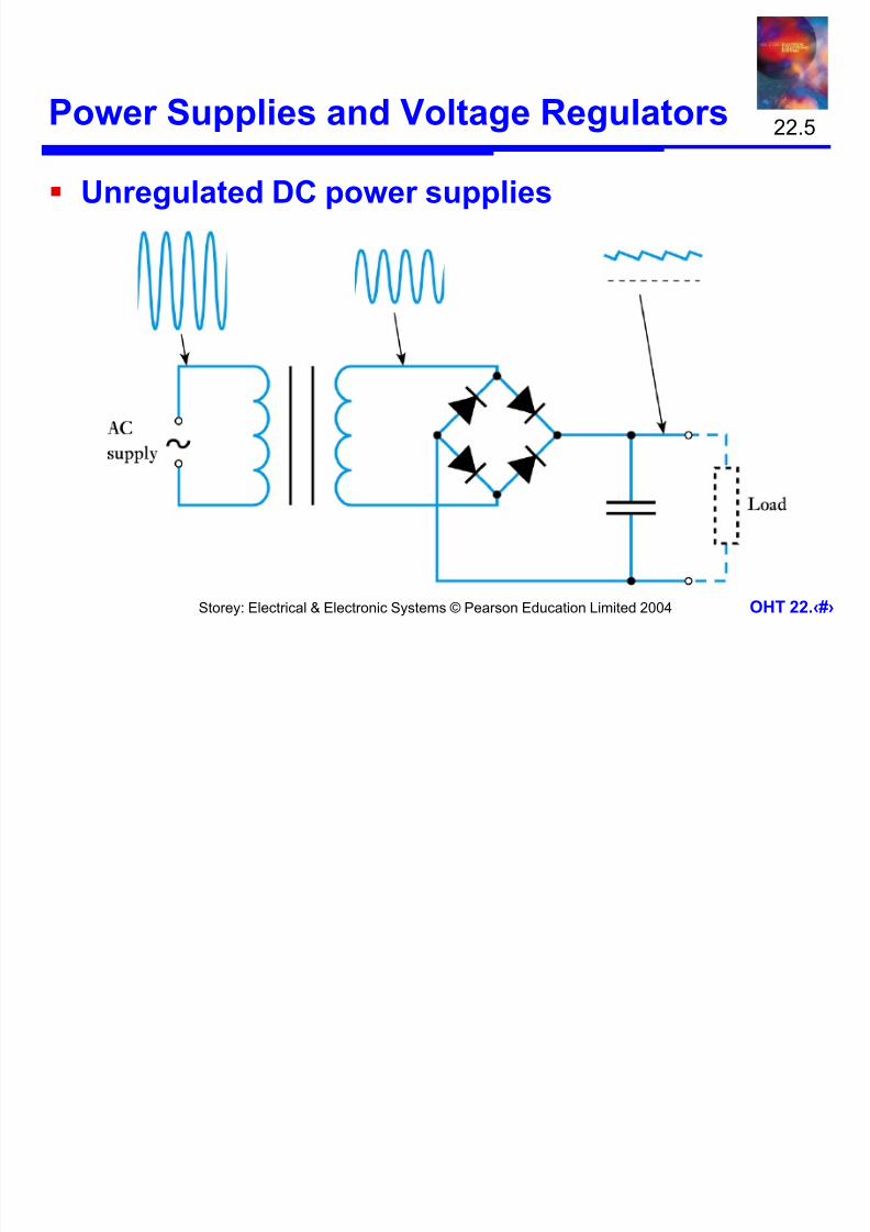
Unregulated DC power supplies
22.5

7/29/2019 Power Amplifiers Chap22
http://slidepdf.com/reader/full/power-amplifiers-chap22 24/29
Storey: Electrical & Electronic Systems © Pearson Education Limited 2004 OHT 22.‹#›
Regulated DC power supplies
7/29/2019 Power Amplifiers Chap22
http://slidepdf.com/reader/full/power-amplifiers-chap22 25/29
Storey: Electrical & Electronic Systems © Pearson Education Limited 2004 OHT 22.‹#›
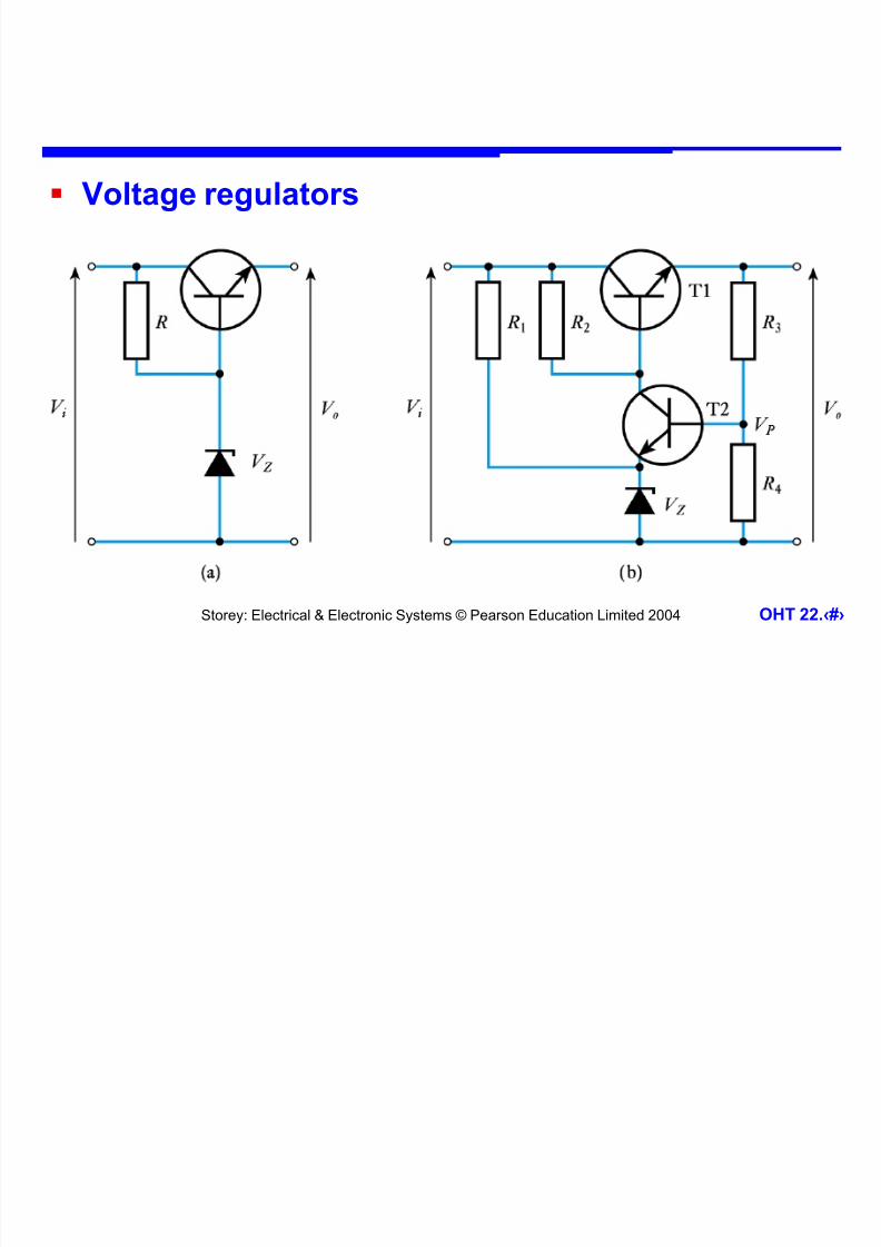
Voltage regulators
7/29/2019 Power Amplifiers Chap22
http://slidepdf.com/reader/full/power-amplifiers-chap22 26/29
Storey: Electrical & Electronic Systems © Pearson Education Limited 2004 OHT 22.‹#›
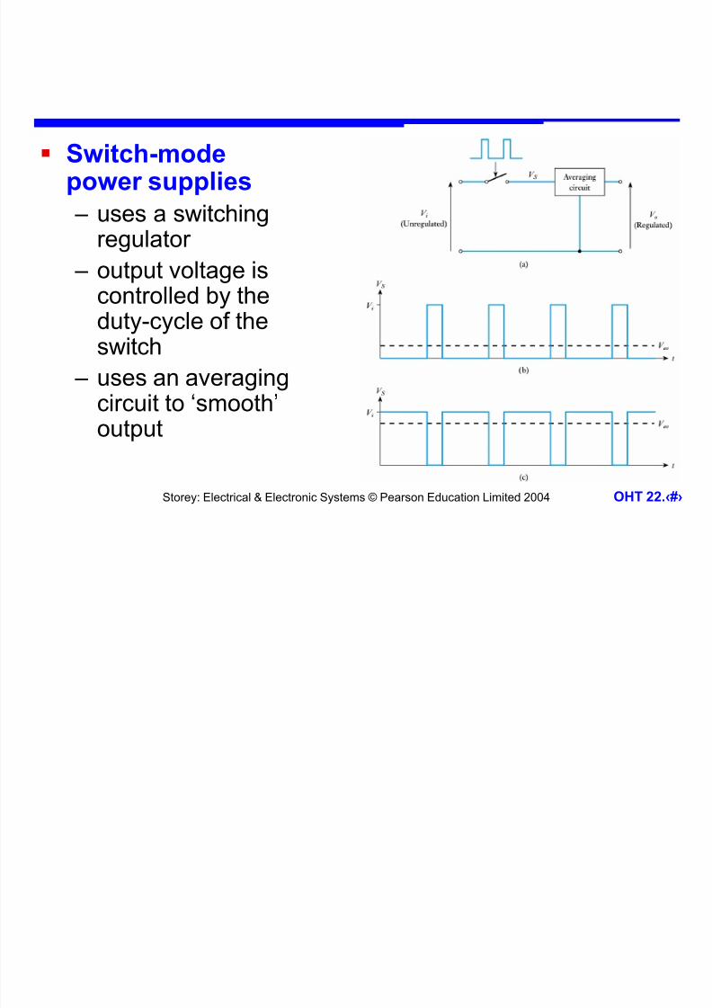
Switch-modepower supplies
– uses a switching
regulator – output voltage is
controlled by theduty-cycle of theswitch
– uses an averagingcircuit to ‘smooth’ output

7/29/2019 Power Amplifiers Chap22
http://slidepdf.com/reader/full/power-amplifiers-chap22 27/29
Storey: Electrical & Electronic Systems © Pearson Education Limited 2004 OHT 22.‹#›
An LC averaging circuit

7/29/2019 Power Amplifiers Chap22
http://slidepdf.com/reader/full/power-amplifiers-chap22 28/29
Storey: Electrical & Electronic Systems © Pearson Education Limited 2004 OHT 22.‹#›
Using feedback in a switching regulator

7/29/2019 Power Amplifiers Chap22
http://slidepdf.com/reader/full/power-amplifiers-chap22 29/29
Storey: Electrical & Electronic Systems © Pearson Education Limited 2004 OHT 22.‹#›
Key Points
Power amplifiers are designed to deliver large amounts of power to their load
Bipolar circuits often use an emitter follower circuit
Many power amplifiers use a push-pull arrangement The efficiency of an amplifier is greatly affected by its class
While transistors make excellent switches, in high power applications we often use special-purpose devices such asthyristors or triacs
A transformer, a rectifier and a capacitor can be used toform a simple unregulated supply
A more constant output voltage can be produced by addinga regulator. This can use linear or switching techniques