Embed Size (px)
Citation preview

IMPORTANT DOCUMENT - DELIVER TO MANAGER
Power Assist Hand TruckTROUBLESHOOTING GUIDE
The Mart Cart® Power Truck is a quality product line of Assembled Products® CorporationThe Challenger hand truck is a quality product of Motor Dolly, LLC
Customer Service: 1-800-548-3373
Models: 610-1300, 610-1301, 610-1304, 610-1305,280-3600, 280-3604, 280-3605
WARNING: Only experienced professionals should attempt to troubleshoot. If you are not an experienced and trainedprofessional in electronics, wiring, and battery-operated machinery, STOP and call an Authorized Service Company.For a list of Authorized Service Companies, call Customer Service at (800) 548-3373.
WARNING: This is a battery-operated device. Failure to observe safe handling procedures when servicing can result in shock.
NOTICE: Attempts to troubleshoot or repair by unauthorized personnel may void your warranty.

2 Customer Service 1-800-548-3373
Figure 1
Figure 2
Battery Level Indicator
Charging Socket
Controller Status Indicator
Main Power Button
Throttle
WHAT’S THE PROBLEM?Reference Page
Setup Status Battery See Charger Power Symptom Indicator Fig.1 Indicator Fig.2 Checks Pages
Unplugged “On” (in)
Unit will not turn “On” “Off” All “Off” A through D 3-7
“Flashing” Red Only D 6-7
Unit will turn “On” “On” All “On” D through E but will not run 6-9
Wiring Diagram and Wiring Schematic . . . . . . . . . . . . . . . . . . . . . . . . . . . . . . . . . . . . . . . . . . . . . . . . . . . . . . . . . . . . . .back cover

3 Customer Service 1-800-548-3373
Figure A1 Figure A2
Battery #1 Battery #1
Yellow (+)Black (-)
Yellow (+)Black (-)
Black (-)Blue (+)
Black (-)Blue (+)
Battery #2 Battery #2
BATTERY AND CHARGING SYSTEMSChecks A-C
A . Battery Voltage Check 1. Detach charger and set the red main power button to “Off” (out). 2. Remove battery cover. 3. Check the voltage of each battery: See Figure A1. Battery #1: Yellow (+) Black (-) Leads Battery #2: Blue (+) Black (-) Leads
Charger Power Unplugged “Off” (out)
Setup: NOTE: “Smart Batteries” are designed to shutdown at approximately 9Vdc.A short charging for only a few minutes will turn the batteries back “On”.If not, replace battery.
Battery #1 Battery #2 Steps See Figure 9 to 12 Vdc 9 to 12 Vdc
Less than 2 Vdc 9 to 12 Vdc Charge both batteries and reconnect. A1
Less than 2 Vdc Less than 2 Vdc
9 to 12 Vdc Less than 2 Vdc Charge both batteries and reconnect after A2 swapping battery locations and leads.
+13 Vdc + 13 Vdc Batteries Operational n/a

4 Customer Service 1-800-548-3373
Figure B1
(-) BATTERY #2 (+) (+) BATTERY #1 (-)
BATTERY AND CHARGING SYSTEMS (continued)Checks A-C
B . Battery Harness and Fuse Check 1. Open the controller and check the voltage of each battery at the battery terminals. See Figure B1.
Note:Battery #2: Blue (+), Black (-) Leads Battery #1: Yellow (+), Black (-) Leads
Figure B2
FUSESBattery #1Harness
Battery #2Harness
Blue
Black
Black
Yellow
Charger Batteries Power Unplugged +13 Vdc “Off” (out)
Setup:
Voltage Possible Cause Steps See Figure Faulty Harness Check the conductivity of Battery Harness, 0 Vdc Replace Battery Harness as needed. B2
Blown Fuse Check the conductivity of Fuses, Replace Fuse as needed.
+13 Vdc – Battery Harness Operational n/a

5 Customer Service 1-800-548-3373
Figure C3
Pin 3 (-)GREEN
Pin 2 (-)BLACK
Pin 1 (+)WHITE
5 PinUNPLUGGED
Figure C1
Status Indicator 5 Pin Unplugged
Figure C2
Pin 1 (+)Pin 2 (-)
Pin 3 (-)
C . Battery Charger Check 1. Disconnect the yellow (+) battery lead from Battery #1 2. Open the controller and unplug controller 5 pin connector. See Figure C1. 3. Reconnect the yellow (+) battery lead to battery #1 4. Plug charger into power outlet and controller charging socket, wait 30 seconds. See Figure C1.
Charger Plug:
Pin 1 (+) White
Pin 2 (-) Black
Pin 3 (-) JumperGreen Pin(unused)
Status Indicator Possible Cause Steps See Figure Unplug Charger from the Controller Charging Socket and check Pin output:
Faulty Charger Plug
Pin1 - Pin2: +13Vdc, If 0Vdc replace Charger Plug, Charger. C2
Pin1 - Pin3: +13Vdc, If 0Vdc replace Charger Plug, Charger.
“OFF” With Charger plugged-in check Pin input:
Faulty Charger Socket Pin1 - Pin2: +13Vdc, If 0Vdc replace Socket. C3
Pin1 - Pin3: +13Vdc, If 0Vdc replace Socket.
Faulty Controller
If both the Plug and Socket pass the above checks, n/a
replace the controller.
“Flashing” – Charging System Operational n/a
BATTERY AND CHARGING SYSTEMS (continued)Checks A-C

6 Customer Service 1-800-548-3373
CONTROLLER, THROTTLE and DRIVE MOTOR SYSTEMSChecks D-E
D . Throttle Assembly and Throttle connections to Controller Check 1. Open controller, check 5 pin and white throttle lead
connecters for secure connection and conductivity. 2. Disconnectcharger and set the red main power button to
“On” (in).
3. Unplug 5 pin from controller. Check ohms between the white throttle lead connecter and P3 (Red) of the 5 pin connecter. See Figure D2.
Figure D1
Figure D2
Charger Batteries Power Unplugged +13 Vdc “Off” (out)
Setup:
Charger Batteries Power 5 pin Connector Unplugged +13 Vdc “Off” (out) Unplugged
Setup:
Pin 1 - Blue or BlackPin 2 - OpenPin 3 - RedPin 4 - YellowPin 5 - Green
Throttle Status Indicator Battery Level Indicator Steps See Figure
All Lights “Off” Check P4 (Yellow) lead of the 5 pin connector,
“Off”
replace 5 pin or Throttle Handle Assembly
All Lights “On” Check P5 (Green) lead of the 5 pin connector, replace 5 pin or Throttle Handle Assembly
Inoperative “Flashing”
Red Light Only
Check P1 (Black or Blue) lead of the 5 pin connector, D1 replace 5 pin or Throttle Handle Assembly
Check P3 (Red) lead of the 5 pin connector, “On” All Lights “On” replace 5 pin or Throttle Handle Assembly
Check White lead, go to next check
Pin 3 - Red Throttle Connector
Ohms Possible Cause Steps See Figure Faulty Connector Check white controller throttle lead connecter, D2
0 replace connector.
Faulty Throttle Replace the Throttle Handle Assembly Handle Assembly
3M to 20M
– Reconnect 5 pin connector. Throttle Assembly Operational, go to next check

7 Customer Service 1-800-548-3373
D . Throttle Assembly and Throttle connections to Controller Check (continued) 4. Using a test lead momentarily (about 3 sec.) jump between
the white throttle lead connecter and either the battery #1 yellow (+) controller terminal or battery #1 yellow (+) battery terminal. See Figure D3.
Charger Batteries Power 5 pin Connector Unplugged +13 Vdc “Off” (out) White Lead to Battery 1 (+)
Setup:
Figure D3
Status Indicator JUMPER
Status Indicator Possible Cause Steps See Figure “Off” Faulty Harness Check white controller throttle lead connecter, D3 replace connector.
“Flashing” – Disconnect the battery #1 yellow (+) lead for 3 seconds then reconnect to reset controller. Controller Throttle Lead operational.
CONTROLLER, THROTTLE and DRIVE MOTOR SYSTEMS (continued)Checks D-E
8 Customer Service 1-800-548-3373
CONTROLLER, THROTTLE and DRIVE MOTOR SYSTEMS (continued)Checks D-E
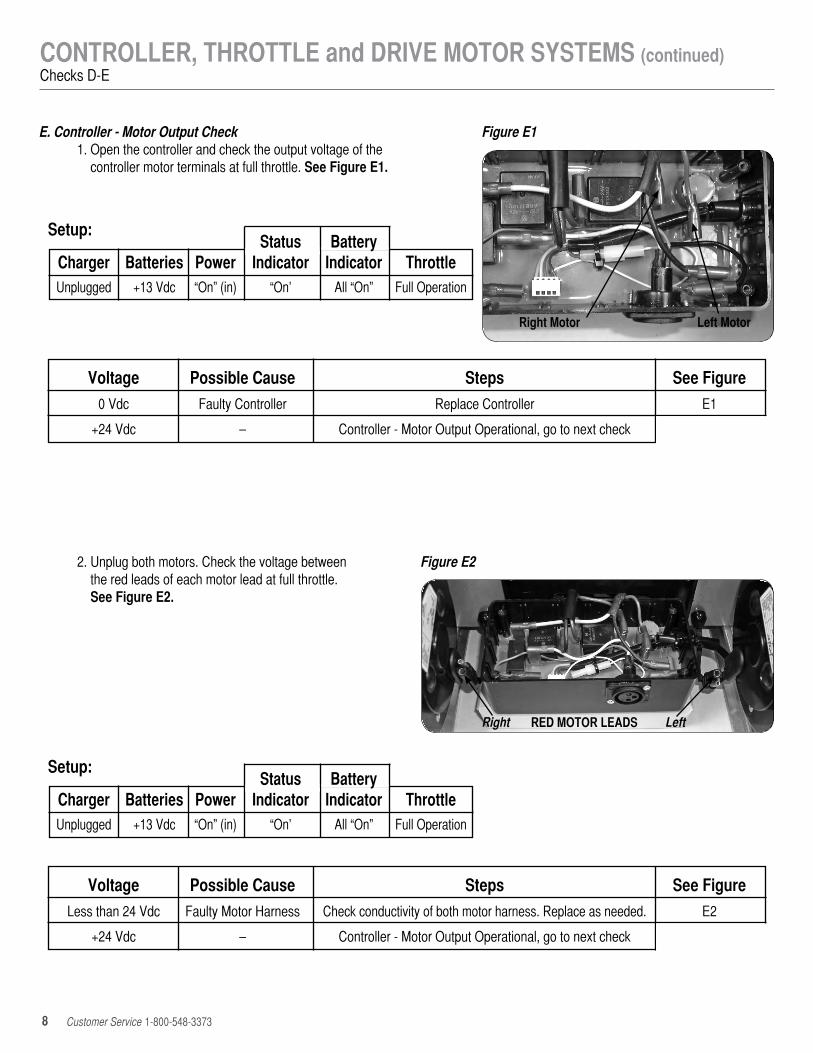
E . Controller - Motor Output Check 1. Open the controller and check the output voltage of the
controller motor terminals at full throttle. See Figure E1.
Figure E1
Right Motor Left Motor
Setup: Status Battery Charger Batteries Power Indicator Indicator Throttle Unplugged +13 Vdc “On” (in) “On’ All “On” Full Operation
Setup: Status Battery Charger Batteries Power Indicator Indicator Throttle Unplugged +13 Vdc “On” (in) “On’ All “On” Full Operation
Voltage Possible Cause Steps See Figure 0 Vdc Faulty Controller Replace Controller E1
+24 Vdc – Controller - Motor Output Operational, go to next check
Voltage Possible Cause Steps See Figure Less than 24 Vdc Faulty Motor Harness Check conductivity of both motor harness. Replace as needed. E2
+24 Vdc – Controller - Motor Output Operational, go to next check
2. Unplug both motors. Check the voltage between the red leads of each motor lead at full throttle. See Figure E2.
Figure E2
RED MOTOR LEADSRight Left

9 Customer Service 1-800-548-3373
Setup: Status Battery Charger Batteries Power Indicator Indicator Controller Unplugged +13 Vdc “On” (in) “On’ All “On” Operational
Motor Possible Cause Steps See Figure Inoperative Faulty Motor Confirm controller motor output (see “E” above) Replace motor as needed. E3
Operative – DRIVE MOTORS (Electrical) Operational
E . Controller - Motor Output Check 3. Unplug one motor and add a wiring “short”
terminator jumper to the unplugged motor lead. See Figure E3.
4. Check motor for operation and repeat E3 for second motor.
Figure E3
Plugged in Jumper

10 Customer Service 1-800-548-3373
TECHNICAL SHEET - 280-3600Power Assisted Convertible Hand Truck
CONVERTIBLE TECH SHEET
1. Exploded View and Parts List a. Replacement Parts List Item Part# Description 1 610-1175 THUMB THROTTLE ASSEMBLY
2 610-1046 DRIVE TIRE/TUBE, PNEUMATIC, 10”
3 610-1226 FREEWHEEL DRIVE HUB, LEFT
4 610-1043 DRIVE SUPPORT ARM, LEFT
5 610-1044 GEARMOTOR ASSEMBLY, LEFT
6 610-1162 CONTROLLER, PWM / CHARGING
7 610-1091 BATTERY BOX, FRONT COVER
8 610-1089 BATTERY, 10AH
9 610-1093 BATTERY BOX
10 610-1045 AXLE, 5/8”
11 610-1013 GEARMOTOR ASSEMBLY, RIGHT
12 610-1159 DRIVE SUPPORT ARM, RIGHT
13 610-1230 FREEWHEEL DRIVE HUB, RIGHT
14 610-1075 CASTER, 3”
15 610-1260 HALF RIM
16 610-1259 HALF RIM W/ VALUE STEM HOLE
17 610-1281 HARNESS, CHARGING PLUG - OFF BOARD
PARTS NOT SHOWN
Part# Description
610-1092 HARNESS, BATTERY #1
610-1094 HARNESS, BATTERY #2
610-1096 HARNESS, GEARMOTOR, RIGHT
610-1170 HARNESS, GEARMOTOR, LEFT
610-1047 DRIVE WHEEL, FLAT-FREE, 10”
610-1262 NOSE PLATE KIT 18 x 7½

11 Customer Service 1-800-548-3373
TECHNICAL SHEET - 280-3601Power Assisted Standard Hand Truck
STANDARD TECH SHEET
1. Exploded View and Parts List a. Replacement Parts List Item Part# Description 1 610-10015 GRIP THROTTLE ASSEMBLY
2 610-1046 DRIVE TIRE/TUBE, PNEUMATIC, 10”
3 610-1226 FREEWHEEL DRIVE HUB, LEFT
4 610-1043 DRIVE SUPPORT ARM, LEFT
5 610-1044 GEARMOTOR ASSEMBLY, LEFT
6 610-1162 CONTROLLER, PWM / CHARGING
7 610-1091 BATTERY BOX, FRONT COVER
8 610-1089 BATTERY, 10AH
9 610-1093 BATTERY BOX
10 610-0011 AXLE WITH KICK RIM, 5/8”
11 610-1013 GEARMOTOR ASSEMBLY, RIGHT
12 610-1159 DRIVE SUPPORT ARM, RIGHT
13 610-1230 FREEWHEEL DRIVE HUB, RIGHT
14 610-1260 HALF RIM
15 610-1259 HALF RIM W/ VALUE STEM HOLE
16 610-1281 HARNESS, CHARGING PLUG - OFF BOARD
17 610-0003 HANDLE, DOUBLE GRIP, 52”
18 610-0002 GRIP, BLACK, 1-1/8”
PARTS NOT SHOWN
Part# Description
610-1092 HARNESS, BATTERY #1
610-1094 HARNESS, BATTERY #2
610-1096 HARNESS, GEARMOTOR, RIGHT
610-1170 HARNESS, GEARMOTOR, LEFT
610-1047 DRIVE WHEEL, FLAT-FREE, 10”
610-1262 NOSE PLATE KIT 18 x 7½”

115 E. Linden Street, Rogers, Arkansas 72756Service (800) 548-3373 | e-mail: [email protected]
Sales (262) 754-6990 | e-mail: [email protected]
MC-PT-TRBL GUIDE-120712 Specifications are subject to change without notice . Printed in the USA.
Wiring DiagramWiring Schematic