Embed Size (px)
DESCRIPTION
Ausgrind is Ausenco’s in-house program used for power-based comminution calculations. Proprietary calculations have been developed and reconciled with unit process operation and benchmarked with plant performance. Ore breakage data from characterisation and variability testwork, equipment geometry, flowsheet configuration, efficiency factors and operating conditions are inputs. Ausgrind contains a database of operating data and circuit types from many operations and over a wide range of ore types and throughputs. These are referenced when developing flowsheets and circuit efficiency factors which correct the specific energy required to grind from the nominated feed size to the specified product size. As circuit efficiency factors are determined in Ausgrind, correction factors such as those listed by Bond and Rowland are not employed.The principal outputs are the total circuit specific energy and the specific energy for each of the components in the comminution circuit. Ausgrind provides a valuable tool for evaluating comminution options and optimising circuit and equipment configurations.Comminution is a pivotal and critical component in most mineral processing operations for several reasons: it liberates the valuable mineral rendering it amenable to subsequent processes; it represents one of the highest capital cost investments for unit processes in the treatment plant; and it contributes a significant component to operating cost due to its high energy requirements. Therefore, determining the most cost-effective circuit and predicting the energy requirement for each unit process to achieve the desired size reduction in the product stream from the comminution circuit are critical tasks for circuit design. This paper describes the Ausgrind approach for estimating power and design of comminution circuits and compares its outcomes to other published approaches. Practical examples are also presented, showing applications for different circuit configurations for comminution operations, such as multi-stage crushing, SAG and ball mill-based circuits.
Citation preview

7/21/2019 Power-based Comminution Calculations Using Ausgrind
http://slidepdf.com/reader/full/power-based-comminution-calculations-using-ausgrind 1/13
Power-based comminution calculations using Ausgrind
Greg Lane, Bianca Foggiatto and Marcos Bueno
Ausenco Services Ltd., Australia
ABSTRACT
Ausgrind is Ausenco’s in-house program used for power-based comminution calculations. Proprietary
calculations have been developed and reconciled with unit process operation and benchmarked with
plant performance.Ore breakage data from characterization and variability testwork, equipment geometry, flowsheet
configuration, efficiency factors and operating conditions are inputs. Ausgrind contains a database of
operating data and circuit types from many operations and over a wide range of ore types and
throughputs. These are referenced when developing flowsheets and circuit efficiency factors which
correct the specific energy required to grind from the nominated feed size to the specified product size. As
circuit efficiency factors are determined in Ausgrind, correction factors such as those listed by Bond and
Rowland are not employed.
The principal outputs are the total circuit specific energy and the specific energy for each of the
components in the comminution circuit. Ausgrind provides a valuable tool for evaluating comminution
options and optimizing circuit and equipment configurations.
Comminution is a pivotal and critical component in most mineral processing operations for several
reasons: it liberates the valuable mineral rendering it amenable to subsequent processes; it represents one
of the highest capital cost investments for unit processes in the treatment plant; and it contributes a
significant component to operating cost due to its high energy requirements. Therefore, determining the
most cost-effective circuit and predicting the energy requirement for each unit process to achieve the
desired size reduction in the product stream from the comminution circuit are critical tasks for circuit
design.
This paper describes the Ausgrind approach for estimating power and design of comminution circuits
and compares its outcomes to other published approaches. Practical examples are also presented, showing
applications for different circuit configurations for comminution operations, such as multi-stage crushing,
SAG and ball mill-based circuits.
INTRODUCTION
The progressive decrease in ore grades in the past decades has led the minerals industry to process ore at
higher rates to achieve the same metal production, driving significant increases in energy consumption.
Determining the most cost-effective circuit and predicting the energy requirement for comminution
circuits has become an even more critical task in concentrator design.

7/21/2019 Power-based Comminution Calculations Using Ausgrind
http://slidepdf.com/reader/full/power-based-comminution-calculations-using-ausgrind 2/13
Von Rittinger (1867 apud Bond, 1961) and Kick (1885 apud Bond, 1961) proposed theoretical comminution
equations based on surface area and particle volume respectively, while Bond (1952) suggested an
empirical relationship that related the power requirement to the length of new cracks formed. Bond’s
equation was developed for the purpose of designing conventional crushing and grinding circuits (crush-
rod-ball mill or crush-ball mill). By the 1970s, the application of conventional circuits tended to be limited
to relatively low capacities. Since then, circuits featuring autogenous (AG) and semi-autogenous (SAG)
mills, often combined with ball mills, have developed a prominent status in the minerals industry. Several
methodologies have been established for designing AG/SAG based grinding circuits and predicting their
energy requirements.
The most frequently used methodologies for calculating energy requirements of comminution circuits
including AG/SAG mills are briefly described in the following section. This paper focuses on the
description of the Ausgrind approach and also compares its outcomes to other published approaches.
Practical examples are presented, showing measured power draw and Ausgrind predictions for different
SAG and ball mill-based circuit configurations.
EXISTING POWER-BASED CALCULATIONS FOR COMMINUTION CIRCUITS
Most modern grinding circuits consist of a primary SAG mill and secondary ball mill. Bond’s method is
widely used for determining the specific energy (Ecs) for crushers, rod mills and ball mills, whilst for
AG/SAG mills, several methodologies have been proposed over recent decades. Bond’s approach consists
of determining the ore characteristics via standardized laboratory testwork, then calculating the Ecs and
the power requirement based on throughput, and finally sizing the industrial machine. Similar to Bond’s
approach, most methodologies for sizing AG/SAG mills involve bench scale testwork for determining Ecs
and empirical equations for calculating mill power and throughput. Some of those methodologies are
briefly described as follows:
MacPherson (1978) created a grinding test that was conducted in a continuous laboratory mill in
closed circuit with a classifier until steady state was achieved. At test completion, size analyses were
carried out and the Ecs computed using power draw and throughput information. The test also
provided insight into how the harder components built up in the mill charge.
Barratt and Allan (1986) proposed the utilization of Bond comminution work indices and an efficiency
factor (fSAG) for determining the AG/SAG circuit Ecs. Using a pilot plant and operating plant database,
Barratt (1989) developed an empirical formula to determine the power requirements for circuits
including SAG and ball mills. The method required a proposed F 80 feed size to the SAG mill, the final
grind size and an estimate of the transfer size between the two mills. This methodology wasincorporated into a computer-based program for the sizing and selection of grinding circuits called
GrindPower (Matthews and Barratt, 1991).
The JKMRC methodology is based on the use of the JKSimMet program (Napier-Munn et al., 2005).
The program includes comminution “black box” models that are calibrated with equipment and
survey data, as well as ore specific parameters such as the drop weight test (JKDWT) “A×b” and the
Bond ball mill work index. The SAG and ball mills power draw is calculated using semi-empirical

7/21/2019 Power-based Comminution Calculations Using Ausgrind
http://slidepdf.com/reader/full/power-based-comminution-calculations-using-ausgrind 3/13
equations, as a function of mill geometry, speed and load. The SAG Power Index (SPI) test was developed by Starkey and Dobby (Starkey and Dobby, 1996) as
the AG/SAG equivalent to the work index test. A SAG mill is operated in closed circuit and the time
required to grind the material to a P 80 of 1.7 mm is used to predict AG/SAG Ecs using power-based
models available within CEET (Comminution Economic Evaluation Tool).
The SAGDesign test was developed by Starkey, Dawson Lab and Outotec to overcome technical
limitations of the SPI (Starkey et al, 2006). The SAGDesign test procedure adopted a laboratory SAG
mill operated in closed circuit. The ground material generated by the SAG mill is used in a subsequent
ball mill Bond-style work index test. By conducting these two tests, the total grinding energy can be
calculated.
Morrell (2004) developed a methodology for predicting grinding circuit Ecs that used two workindices: one related to a coarse range (stages prior to ball milling) and the other to a fine range
(conventional ball milling). The size selected as the threshold between coarse and fine grinding was
0.75 mm. SMC test results are used to determine drop-weight indices (DWi). The work index related
to coarse grinding (Mia) is calculated from the data output of the SMC test. The Bond ball mill work
index test is used to calculate the work index related to fine grinding (Mib). Mia and Mib are used to
calculate Ecs for the coarse (Wa) and fine (Wb) components according to the equations published by
Morrell (2009). The sum of Wa and Wb results in the total Ecs to reduce the crusher product to the ball
mill product.
Sidall and Putland (2007) published the OMC (Orway Mineral Consultants) method to calculate
grinding power requirement, based on laboratory tests that defined the high and low energy breakage
characteristics. High energy breakage tests such as the autogenous media competency test (AMCT), JKDWT, SPI or SAGDesign test are twinned with a low energy breakage test such as Bond ball work
index. Standardize feed and product sizes are used to calculate the overall energy requirements using
Bond’s formula and a fSAG efficiency factor. The OMC database is then used to select viable options of
circuit configuration for detailed analysis.
Burgess (2012) developed the DBC (Don Burgess Consulting) methodology for calculating grinding
energy using Bond’s comminution theory, which is used to calculate the Ecs of individual
comminution ranges using breakage characterization indexes obtained from Bond’s crusher, rod and
ball mill tests and the JKDWT. The parameters obtained from the JKDWT are converted to
grindability work indexes and AG/SAG Ecs is calculated and corrected when variations occur to
standard parameters such as specific gravity, A×b values and mill aspect ratio.
AG/SAG CIRCUIT SPECIFIC ENERGY (ECS) AND EFFICIENCY FACTORS
The methods available for determining the Ecs requirements for AG/SAG based circuits rely on
combinations of ore breakage tests and Bond-style power based models. The JKMRC methodology is the
only commonly used method that uses a breakage/classification model with empirical factors. The use of
Bond work indices associated with other breakage tests has become a standard for measuring ore
7/21/2019 Power-based Comminution Calculations Using Ausgrind
http://slidepdf.com/reader/full/power-based-comminution-calculations-using-ausgrind 4/13
hardness and establishing comminution energy requirements. Nevertheless, all these methods rely on theuse of efficiency factors to correct the comminution circuit energy requirements. Ausgrind also uses the
Bond work indices, along with JKDWT, SMC, SPI or MacPherson index, as inputs for calculating the
comminution circuit Ecs.
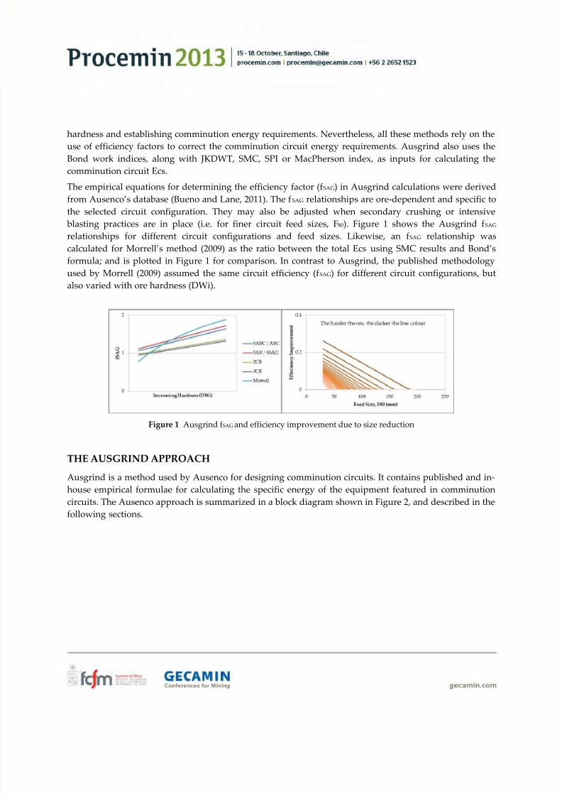
The empirical equations for determining the efficiency factor (fSAG) in Ausgrind calculations were derived
from Ausenco’s database (Bueno and Lane, 2011). The fSAG relationships are ore-dependent and specific to
the selected circuit configuration. They may also be adjusted when secondary crushing or intensive
blasting practices are in place (i.e. for finer circuit feed sizes, F80). Figure 1 shows the Ausgrind fSAG
relationships for different circuit configurations and feed sizes. Likewise, an f SAG relationship was
calculated for Morrell’s method (2009) as the ratio between the total Ecs using SMC results and Bond’s
formula; and is plotted in Figure 1 for comparison. In contrast to Ausgrind, the published methodology
used by Morrell (2009) assumed the same circuit efficiency (fSAG) for different circuit configurations, but
also varied with ore hardness (DWi).
Figure 1 Ausgrind fSAG and efficiency improvement due to size reduction
THE AUSGRIND APPROACH
Ausgrind is a method used by Ausenco for designing comminution circuits. It contains published and in-
house empirical formulae for calculating the specific energy of the equipment featured in comminution
circuits. The Ausenco approach is summarized in a block diagram shown in Figure 2, and described in the
following sections.

7/21/2019 Power-based Comminution Calculations Using Ausgrind
http://slidepdf.com/reader/full/power-based-comminution-calculations-using-ausgrind 5/13
Figure 2 Ausenco methodology for comminution circuit design
Project Concept Definition
Determining the project concept is a fundamental activity that establishes the operating basis and
precedes all other tasks when designing a comminution circuit. Initial considerations to define the project
concept must contemplate the location of the orebody, nature of the ore (preliminary characteristics), local
environmental restrictions, product specifications as well as water availability and energy costs. Based on
such considerations, a conceptual processing route to obtain the plant final product is established. Table 1
shows a matrix for preliminary circuit selection which is reflects plant size (throughput) and ore
competency relationships.
Table 1 Matrix for circuit selection based on throughput and competency (Updated from Lane et al.,2002)
Throughput High Competency Moderate Competency Low Competency
<0.5 Mt/a Stage crush with ball millOne or two stage crush to SAG or
ball mill
Single stage SAG
mill
0.5 to 2 Mt/aStage crush with ball mill or
SAG and ball mill with pebble crushSAG and ball mill
Single stage SAG
mill or
SAG and ball mill
1 to 5 Mt/a SAG and ball mill with pebble crushSAG and ball mill or
AG and ball mill with pebble crush
Single stage SAG
mill or
SAG and ball mill
5 to 10 Mt/a SAG and ball mill with pebble crushSAG and ball mill or
AG and ball mill with pebble crushSAG and ball mill
>10 Mt/a SAG and ball mill with pebble crush orStage crush, HPGR and ball mill SAG and ball mill with pebblecrush SAG and ball mill
This matrix is used as an indication for circuit selection. However, it must be carefully adapted when
problematic ore types present in the deposit can influence the performance of specific stages of the plant.
Sample Selection
Once the preliminary project concepts are defined, the next step is to establish the attributes of the

7/21/2019 Power-based Comminution Calculations Using Ausgrind
http://slidepdf.com/reader/full/power-based-comminution-calculations-using-ausgrind 6/13
testwork program. The testwork program must include appropriate ore characterization tests that arechosen to describe the orebody breakage properties. A detailed evaluation of geology through the
inspection of drill cores and geological sections is required when defining the comminution testwork
program. These inspections allow identification of relationships between the variability of ore
competency/hardness and the lithologies, rock types and mineralization.
The number and type of samples is dependent on the size and status of the project, project risk profile,
acceptable contingencies in defining equipment sizes, capital cost and operating cost. Typically, the
testwork program is divided into three phases. The first phase occurs during the scoping and
prefeasibility studies and samples are selected on the basis of major known rock types. The second and
third phases occur during the feasibility study. The second phase focusses on variability analysis across
the orebody where discrete samples are tested and compared with geometallurgical indicators.
Throughput and operating costs are forecasted more accurately with a relatively higher amount of
samples. For the third phase, samples are composited on the basis of spatial representativity, mine period
production, or hard wired ore typing. Table 2 shows the recommended number of samples for the last
phase of the testwork.
Table 2 Required number of samples during feasibility studies
Basis Number of samples Comments
spatial representativity >100 includes samples from Phase 1 and 2
mine period production 5 to 8 excludes samples from Phase 1 and 2
hard wired ore typing 10 to 30 includes samples from Phase 1 and 2
Breakage Characterization Testwork
As described in the previous sections, several methods are available for testing breakage characteristics.
Ausgrind typically uses results from the following tests, depending on the circuit configuration under
evaluation: Bond tests (crushing - CWI, rod mill - RWI, ball mill - BWI), SMC test and/or JKDWT.
The SMC test and the JKDWT directly yield values of DWi and A×b. The DWi is obtained from the
relationship between input energy (kWh/t), specific gravity and a size distribution index (t 10) obtained for
the SMC test or JKDWT product. The DWi is directly related to the JKMRC rock breakage parameters A
and b. As the SMC test does not use particles greater than 31.5 mm, its results can be biased when testing
extremely competent ores (A×b values lower than 35). Therefore, JKDWT data are typically used to
calibrate the SMC results. If breakage characterization testwork was conducted using other methodologies
such as the MacPherson’s autogenous milling test or SPI, empirical formulae based on Ausenco’s database
are used to correlate the outcomes with Ausgrind model input parameters.
Comminution Circuit Energy
The Ausgrind program calculates the total Ecs for the grinding circuit as a product of the calculated Bond
Ecs and the energy efficiency factor (fSAG). The Bond Ecs is calculated using the CWi, RWi, and BWi to
determine the specify energy requirements of a crush-rod-ball mill circuit for a P 80 of 150 microns as per
the Bond formulae without any correction factors such as those listed by Bond, Rowland and others. If the

7/21/2019 Power-based Comminution Calculations Using Ausgrind
http://slidepdf.com/reader/full/power-based-comminution-calculations-using-ausgrind 7/13
product size (P80
) is different to 150 microns, the energy difference is calculated as per the Bondrelationship. The Ausgrind total Ecs calculation is described in the equation below.
Total Ecs = [(Bond Ecs to 150µm) * (f SAG – F80_effect)] ± [Bond Ecs to final P80]
The base case SAG mill Ecs is calculated as function of ore competency (in this case as measured by the
DWi), as shown in Figure 4.
Figure 4 SAG Ecs relationship with ore hardness (DWi)
A series of factors are then applied to adjust the base case SAG Ecs for the operating conditions, mill
dimensions (e.g. aspect ratio) and others. Some of these adjusting factors are shown in Figure 5 and the
SAG Ecs calculation is described in the equation below.
SAG Ecs = [Base Case SAG Ecs] * [adjusting factors]
Figure 5 Adjusting factors to SAG Ecs
The pebble crusher Ecs is calculated separately and vendor data is used for equipment selection.
The ball mill specific energy is calculated as the residual using the following equation:

7/21/2019 Power-based Comminution Calculations Using Ausgrind
http://slidepdf.com/reader/full/power-based-comminution-calculations-using-ausgrind 8/13
Ball mill Ecs = Total grinding circuit Ecs – SAG mill EcsFor circuits without a SAG mill, the ball mill specific energy equals to the total grinding circuit specific
energy. Similarly, for circuits without ball mills, the SAG mill specific energy equals to the total grinding
circuit specific energy. Mill shell and motor size selection considers the specific energy requirements and
the specified plant throughput, together with the expected operating envelope of each mill.
BENCHMARKING AUSGRIND
As several tests have been developed to suit the requirements of AG/SAG circuit design, the different
testwork methods and interpretation of their results can produce very different outcomes. Differences in
SAG mill Ecs determination and throughput predictions, particularly for competent ores (Bailey et al.,
2009), motivated Ausenco to benchmark the Ausgrind model. This section includes comparisons of theAusgrind outcomes with operational data of the SABC circuit from Newcrest’s Cadia concentrator and
also other published approaches.
Cadia
Ausgrind was used to calculate the energy requirements of the Cadia SABC circuit using information
available in the literature (Dunne et al., 1999, Dunne et al., 2001, Hart et al., 2001). The grinding circuit
data input used for the calculation are listed in Table 3. The information on ore characteristics in this table
refers to the monzonite ore. The SAG mill operating conditions were obtained from Dunne et al. (2001).
Table 3 Cadia grinding circuit data input for Ausgrind calculations
Ore Value Unit SAG Mill Data Value Unit
JK or SMC parameters (A×b) 36 No Mills 1
SG 2.7 t/m3 Diameter (inside shell) 12.2 m
DWi 7.5 Aspect ratio (L/D) 0.5
Bond crusher work index 16.5 kWh/t Effective Grinding Length, EGL 6.1 m
Bond rod mill work index 19.0 kWh/t Fraction of crit. speed 0.72
Bond ball mill work index 17.1 kWh/t Ball volume (nominal design) 12 %
Total filling (nominal design) 25 %
Crusher Circuit Value Unit Discharge slurry % solids 70 %
Throughput - Primary crusher 4000 t/h
Primary crusher circuit F80 335 mm Ball Mill Data Value Unit
Primary crusher circuit CSS 120 mm No Mills 2
Crushing circuit P80 98 mm Diameter 6.7 m
Aspect ratio (L/D) 1.68
Grinding Circuit Value Unit Belly length inside liners 11.3 m
Throughput - Grinding 2065 t/h Fraction of crit. speed 0.72
Cyclone overflow P80 170 micron Ball volume 30 %
Select circuit type SABC Discharge slurry % solids 70 %
The specific energy measured during the survey (Dunne et al., 2001) and that calculated using Ausgrind

7/21/2019 Power-based Comminution Calculations Using Ausgrind
http://slidepdf.com/reader/full/power-based-comminution-calculations-using-ausgrind 9/13
are listed in Table 4.
Table 4 Ausgrind calculations for the Cadia SABC circuit
MethodSpecific energy - Ecs (kWh/t) ∆
(kWh/t)SAG mill Ball mill Total
Ausgrind 8.8 8.8 17.6 -
Survey (1998) 8.6 8.0 16.6 - 1.0
Comparison with Other Methodologies
The Ausgrind method was compared to other techniques described in this paper using values published
in journal and conference papers available in the public domain. Seven papers were selected: Morrell,
2009; Starkey and Holmes, 2001; Marks et al., 2001; Becerra and Amelunxen, 2012; Burgess, 2012 andDelboni et al., 2006. The results are presented in Table 5 and contain comparative calculations for the
following cases:
Morrell’s (2009) paper describes the SMC methodology for predicting the overall Ecs of comminution
circuits. The information regarding the SABC worked example was used for calculating and
comparing Ecs.
Starkey and Holmes’ (2001) paper shows the design of the Kubaka gold ore grinding circuit using SPI
and Bond test parameters. According to the authors, the previous characterization testwork was
carried out for the harder ores of the deposit and included the MacPherson autogenous work index,
Bond rod and ball mill work indices and SPI tests. Both MacPherson and Starkey power estimates are
compared to the Ausgrind calculation.
The Similco SACB grinding circuit was designed using the JKTech and SGS characterization databases
which included JKDWT and Bond rod and ball mill work indices (Marks et al., 2001). For design of the
circuit, the authors used the FLSmidth in-house mill selection criteria.
Becerra and Amelunxen (2012) published the study for the Confluencia SACB grinding circuit at the
Los Bronces copper deposit. In this study, three methodologies were used to analyze the energy
requirements: MillPower, JKSimMet and Aminpro in-house methodology. The comminution testwork
conducted included Bond rod and ball mill work indices, Bond abrasion index, SPI and SMC testes.
Median values for all the parameters were used for comparison with the Ausgrind calculations.
The DBC method for calculating AG/SAG Ecs uses a combination of Bond work indices and the drop
weight test parameters. The author published a paper (Burgess, 2012) comparing his methodology
with the SMC method for three ore competencies (soft, medium and hard) and producing a final
product of 0.075 mm, 0.107 mm and 0.75 mm, respectively. The single stage SAG circuit was used for
the selected three examples. Since Ausgrind does not consider this circuit configuration for hard ores,
only Ecs values for soft and medium ores were calculated for comparison.
The Sossego SABC grinding circuit was dimensioned under the consultancy of Delboni (2006) using a
combined method of JKSimMet and an in-house power-based empirical model.

7/21/2019 Power-based Comminution Calculations Using Ausgrind
http://slidepdf.com/reader/full/power-based-comminution-calculations-using-ausgrind 10/13
Table 5 Ausgrind benchmarked against other methodologies
ExampleCircuit
configurationMethod
Specific energy (kWh/t) ∆
(kWh/t)SAG mill Ball mill Total
SMC worked
exampleSABC
Ausgrind 8.1 10.0 18.1 -
SMC 9.6 8.4 18.3 + 0.2
Kubaca circuit SAB
Ausgrind 11.8 14.1 25.9 -
MacPherson 10.9 14.0 24.9 - 1.0
Starkey 13.4 16.4 29.8 + 4.1
Similco circuit SACBAusgrind 12.0 14.6 26.6 -
FLSmidth 8.0 16.0 24.3 - 2.3
Confluencia
circuit
SACB
Ausgrind 5.7 10.4 16.1 -
MillPower 6.2 9.2 15.7 - 0.4
JKSimMet 5.5 9.5 15.3 - 0.8Aminpro 6.3 8.3 14.9 - 1.2
DBC worked
example - soft
ore
SSAG
Ausgrind 16.6 - 16.6 -
DBC 17.4 - 17.4 + 0.8
SMC 16.8 - 16.8 + 0.2
DBC worked
example -
medium ore
SSAG
Ausgrind 18.0 - 18.0 -
DBC 17.0 - 17.0 - 1.0
SMC 17.2 - 17.2 - 0.8
Sossego circuit SABCAusgrind 9.6 6.7 16.3 -
Delboni 10.8 8.7 19.5 + 3.2
The delta ( ∆ ) in Table 5 is the difference in the total grinding specific energy between calculations with
Ausgrind and the other methods. According to Table 5, the lowest delta values were obtained when
comparing Ausgrind and the SMC method (+ 0.2 and – 0.8 kWh/t). The highest delta values were obtainedwhen comparing Ausgrind and Starkey’s method for the Kubaca circuit (+ 4.1 kW/t, a 15% difference) and
Delboni’s method for the Sossego circuit (+ 3.2 kWh/t, a 20% difference). The specific energy predictions
for the other examples resulted in delta values lower than 2.3 kWh/t, meaning that the relative difference
was within a range from 2 to 9%.
Comparison with Plant Surveys
Ausgrind specific energy predictions were compared to measured values during surveys in three
comminution circuits which processed hard ores. The results showed good agreement, and are presented
in Figure 6.

7/21/2019 Power-based Comminution Calculations Using Ausgrind
http://slidepdf.com/reader/full/power-based-comminution-calculations-using-ausgrind 11/13
Figure 6 Ausgrind benchmark against plant surveys
CONCLUSIONS
A number of well-established methodologies used for calculating comminution energy requirements have
been presented in this paper. The published results from these methodologies were used to benchmark
the Ausgrind program. Ausgrind reproduced the specific energy requirements calculated by other
methods for various projects within ± 10% accuracy, with only a few exceptions, and predicted within 5%
the survey data from four different operations. Therefore, Ausgrind has demonstrated that its
methodology is a suitable and reliable method for designing AG/SAG milling circuits.
Every approach discussed in this paper relies on the use of efficiency factors (directly or indirectly) to
correct the Bond comminution circuit energy requirements for an AG/SAG circuit. Some methods are
more conservative than others, resulting in different efficiency factors and estimated energy requirements.
Notwithstanding the merits of comminution methodologies, the representativity of sample selection, the
applicability of the testwork and the quality of testwork data are critical for the success of any circuit
design. In light of this, the Ausgrind method includes a guideline for best practice in obtaining quality
input data.
ACKNOLEDGMENTS
The authors would like to thank Ausenco Services for the permission to publish this paper. Eddie McLean
is also acknowledged for his valuable comments and revision on the paper.
REFERENCES
Bailey, C., Lane, G., Morrell, S. and Staples, P. (2009) ‘What can go wrong in comminution circuit design?’,
In Proceedings of the 10th Mill Operators’ Conference , pp. 143–149, Mill Ops 2009. AusIMM:
Melbourne.
Barratt, D.J. and Allan, M.J. (1986) ‘Testing for autogenous and semiautogenous grinding: a designer’s
point of view’, Minerals and Metallurgical Processing , pp. 65– 74.

7/21/2019 Power-based Comminution Calculations Using Ausgrind
http://slidepdf.com/reader/full/power-based-comminution-calculations-using-ausgrind 12/13
Barratt, D. J. (1989) ‘An update on testing, scale-up and sizing equipment for autogenous and semi-autogenous grinding circuits’, In Mular, A. L. and Agar, G. E. (Eds.) Proceeding of Advances in
Autogenous and Semi-Autogenous Grinding Technology, pp. 25–46, SAG 1989. UBC: Vancouver.
Bond, F.C. (1952) ‘The third theory of comminution’, Transaction of the AIME , 193, pp. 484– 494.
Bond, F. C. (1961) ‘Crushing & grinding calculations part I’, British Chemical Engineering , 6:378–385.
Bueno, M. and Lane, G. (2001) ‘A Review of 10 Years of AG/SAG Pilot Trials’, In Major, K., Flintoff, B. C.,
Klein, B. and McLeod, K. (Eds.), Proceedings of the International Autogenous Grinding Semi-
autogenous Grinding and High Pressure Grinding Roll Technology , SAG 2011. UBC: Vancouver.
Becerra, M. and Amelunxen, P. (2012) ‘A comparative analysis of grinding circuit design methodologies’,
In Proceedings of the 9th International Mineral Processing Conference , Procemin 2012 , pp. 468–476,
Santiago.
Burgess, D. (2012) ‘A method of calculating autogenous/semi-autogenous grinding mill specific energies
using a combination of Bond work indices and Julius Kruttschnitt parameters, then applying
efficiency factors’, In Proceedings of the 11th Mill Operators’ Conference , MillOps 2012. AusIMM:
Hobart, pp. 37–44.
Delboni, H., Rosa, M. A. N., Bergerman, M. G. and Nardi, R. P. (2006) ‘Optimisation of the Sossego SAG
mill’, In Allan, M. J., Major, K., Flintoff, B. C., Klein, B. and Mular, A. L. (Eds.) Proceedings of the
International Conference on Autogenous and Semi-Autogenous Grinding Technology , pp. 39–50, SAG
2006. UBC: Vancouver.
Starkey J. and Dobby, G. (1996) ‘Application of the Minnovex SAG Power Index at five Canadian SAG
plants’ , In Mular, A. L., Barratt, D. J. and Knight, D. A. (Eds.) Proceedings of the InternationalConference on Autogenous and Semi-Autogenous Grinding Technology , pp. 345–360, SAG 1996. UBC:
Vancouver.
Dunne, R. Chittenden, R., Lane, G. and Morrell, S. (1999) ‘The Cadia gold copper project exploration to
start up’, In SME Annual Meeting. Preprint 90-160. SME: Denver.
Dunne, R., Morrell, S., Lane, G., Valery, W. and Hart, S. (2001), ‘Design of the 40 foot diameter SAG mill
installed at the Cadia Gold Copper Mine’, In Barratt, D. J., Allan, M. J. and Mular, A. L. (Eds.)
Proceedings of the International Conference on Autogenous and Semi-Autogenous Grinding Technology ,
pp. 43–58, SAG 2001. UBC: Vancouver.
Hart, S., Valery, W., Clements, B., Reed, M., Song, M. & Dunne, R. (2001) ‘Optimisation of the Cadia Hill
SAG mill circuit’, In Barratt, D. J., Allan, M. J. and Mular, A. L. (Eds.) Proceedings of the InternationalConference on Autogenous and Semi-Autogenous Grinding Technology , pp. 11–30, SAG 2001. UBC:
Vancouver.
Lane, G.S., Fleay, J., Reynolds, K., and La Brooy, S., (2002) ‘Selection of comminution circuits for improved
efficiency’, In Proceedings of the Crushing and Grinding Conference. Kalgoorlie.
MacPherson, A. R. (1978) ‘A simple method to predict the autogenous grinding mill requirements for

7/21/2019 Power-based Comminution Calculations Using Ausgrind
http://slidepdf.com/reader/full/power-based-comminution-calculations-using-ausgrind 13/13
processing ore from a new deposit’, Transaction of the AIME , 262, pp. 236–240.Marks, A., Sams, C. and Major, K. (2001) ‘Grinding circuit design for Similco mines’, In Major, K., Flintoff,
B. C., Klein, B. and McLeod, K. (Eds.) Proceedings of the International Autogenous Grinding Semi-
autogenous Grinding and High Pressure Grinding Roll Technology , SAG 2011. UBC: Vancouver.
Morrell, S. (2004) ‘Predicting the specific energy of autogenous and semi-autogenous mills from small
diameter drill core samples’, Minerals Engineering , 17 (3): pp. 447–451.
Morrell, S. (2009) ‘Predicting the overall specific energy requirement of crushing, high pressure grinding
roll and tumbling mill circuits’, Minerals Engineering , 22 (6): pp. 544–549.
Napier-Munn, T. J., Morrell, S., Morrison, R. D. and Kojovic, T. (2005) ‘ Mineral comminution circuits: their
operation and optimisation’, Julius Kruttschnitt Mineral Research Centre: Brisbane.
Rowland, C. A. (1972) ‘Grinding calculations related to the application of large rod and ball mills ’,
Canadian Mining Journal , v. 93 (6).
Siddall, B.; Putland, B. (2007) ‘Process Design And Implementation Techniques For Secondary Crushing
To Increase Milling Capacity’, In SME Annual Meeting. Preprint 07-079. SME: Salt Lake City.
Starkey, J. and Holmes, G. (2001) ‘Design of the Kubaca grinding circuit using SPI and Bond ’, In
Proceedings of the Canadian Mineral Processors Conference. CMP 2001. Ottawa.
Starkey, J., Hindstrom, S. and Nadasdy, G. (2006) ‘SAGDesign testing – what it is and why it works’, In
Allan, M. J., Major, K., Flintoff, B. C., Klein, B. and Mular, A. L. (Eds.) Proceedings of the
International Conference on Autogenous and Semi-Autogenous Grinding Technology , pp. 240–254, SAG
2006. UBC: Vancouver.