Embed Size (px)
Citation preview

A S A TECHNICAL NOTE
kwL O A N C O P Y : R:;. -=AFWL TECHN:Ch!. -KIRTLAND AFE E=
POWER CALCULATIONS FOR ISENTROPIC COMPRESSIONS OF CRYOGENIC NITROGEN
Jerry B. Adcock and Marilyn E . Ogbum
Laq$ey Research Center >i
Humpton, Va. 23665
NATIONAL AERONAUTICS AND SPACE ADMINISTRATION WASHINGTON, D. C. MARCH 1977
https://ntrs.nasa.gov/search.jsp?R=19770013434 2018-06-24T04:54:41+00:00Z

1. Report No. 1 2. Government Accession No NASA TN D-8389 I-
4. Title wid Subtitle
POWER CALCULATIONS FOR ISENTROPIC COMPRESSIONS OF CRYOGENIC NITROGEN
7. Author(s)
Jerry B. Adcock and Marilyn E. Ogburn
9. Performing Organization Name and Address
NASA Langley Research Center Hampton, VA 23665
2. Sponsoring Agency Name and Address
National Aeronautics and Space Administration Washington, DC 20546
5. Supplementary Notes
6. Abstract
TECH LIBRARY KAFB, NM
II 0234244 II
5. Report Date krch 1977
I 6. Performing Organization Code
8. Performing Organization Report No.
L-11184
, 10.Work Unit No.
505-06-42-01 11. Contract or Grant No.
13. Type of Report and Period Covered
Technical Note 14. Sponsoring Agency Code
A theoretical analysis has been made of the power required for isentropic compressions of cryogenic nitrogen in order to determine the extent to which the drive power for cryogenic tunnels might be affected by real-gas effects. The analysis covers temperatures from.80 to 310 K, pressures from 1.0 to 8.8 atm, and fan pressure ratios from 1.025 to 1.200. The power required to compress cryogenic nitrogen was found to be as much as 9.5 percent lower than that required to compress an ideal diatomic gas. Simple corrections to the ideal-gas values were found to give accurate estimates of the real-gas power values.
7. Key Words (Suggested by Author(s)) 18. Distribution Statement
Real gas Wind tunnel Unclassified - Unlimited Nitrogen Isentropic compression Cryogenics Power
Subject Category 34
9. Security Classif. (of this report) 20. Security Classif. (of this page) 21.NO. o f pages 22. Rice.
Unclassified Unclassified 69 $4.50
POWER CALCULATIONS FOR ISENTROPIC COMPRESSIONS
OF CRYOGENIC NITROGEN
J e r r y B. Adcock and Marilyn E. OgburnLangley Research Center
SUMMARY
A t h e o r e t i c a l a n a l y s i s has been made o f t h e power .required f o r i s e n t r o p i ccompressions of cryogenic n i t rogen . This real-gas a n a l y s i s was made from a cryogenic wind-tunnel p e r s p e c t i v e , and t h e purpose o f t h e a n a l y s i s was to. determine t h e e x t e n t t o which wind-tunnel d r i v e power might be a f f e c t e d by t h e real-gas c h a r a c t e r i s t i c s o f n i t rogen . The real-gas s o l u t i o n s covered s t agna t ion temp e r a t u r e s from 80 t o 310 K , s t agna t ion p res su res from 1.0 t o 8.8 atm, and fan p res su re r a t i o s from 1.025 t o 1.200. These s o l u t i o n s are compared t o t h e i d e a l diatomic gas s o l u t i o n s . A t cryogenic tempera tures , t h e power r equ i r ed t o comp r e s s n i t rogen i s e n t r o p i c a l l y is as much as 9 .5 percent lower than tha t r equ i r edf o r t h e ideal gas. Simple c o r r e c t i o n s t o t he ideal va lues o f mass flow, energy,and power were found t o g i v e accu ra t e estimates of the real-gas va lues .
INTRODUCTION
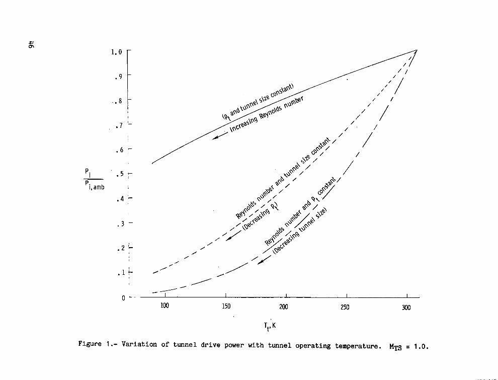
The cryogenic wind-tunnel concept has been developed a t t h e LangleyResearch Center i n o rde r t o improve f l i g h t simulat.ion i n wind tunne l s byinc reas ing t h e test Reynolds number. The major advantages of i nc reas ing t h e Reynolds number by reducing t h e temperature of t h e test gas are given i n references 1 t o 4 . For fan-driven t u n n e l s , one of t h e prime advantages o f reducingthe temperature of the test gas is the accompanying r educ t ion i n t h e requi redd r i v e power. The e x t e n t of t h i s r educ t ion is i l l u s t r a t e d i n f i g u r e 1 f o r t h r e e d i f f e r e n t wind-tunnel ca ses . I n each case two o f t h e three tunne l parameters(Reynolds number, s t a g n a t i o n p res su re , and s i z e ) are he ld cons t an t whi le t he t h i r d v a r i e s wi th decreas ing s t agna t ion temperature. These c a l c u l a t i o n s are based on the assumption of an idea l gas. However, f o r t he cryogenic wind-tunnel concept as developed a t Langley, cool ing is accomplished wi th l i q u i d n i t rogen ; t h e r e s u l t i n g t e s t gas is cryogenic n i t rogen . A t these cond i t ions , n i t rogen has real-gas imperfec t ions (ref. 5 ) . Even though the a n a l y s i s o f r e fe rence 5 ind ica t ed t h a t cryogenic n i t rogen would be an accep tab le tes t gas i n terms of flow s imula t ion , t h e real-gas c h a r a c t e r i s t i c s could poss ib ly become important i n a wind-tunnel des ign cons ide ra t ion such as the d r i v e power requirement.
This r e p o r t p r e s e n t s t h e r e s u l t s o f a s tudy t o determine the e x t e n t t o which the wind-tunnel drive-power requirements might be affected by t h e real-gas c h a r a c t e r i s t i c s o f n i t rogen . I n t h i s s tudy , real-gas s o l u t i o n s for i s e n t r o p i c compressions of n i t rogen were made f o r t he range o f ope ra t ing temperatures ( s a t u r a t i o n s t o 310 K ) , p r e s su res (1.0 to 8.8 a t m ) , and tunne l p re s su re r a t i o s (1.025 t o 1.200) a n t i c i p a t e d f o r fan-driven t r a n s o n i c cryogenic

- -
twind tunne l s . The’ s o l u t i o n s were compared wi th those for an ideal diatomic gas, and the r e s u l t s are presented r e l a t i v e t o the ideal-gas va lues . Real-gas c a l c u l a t i o n s f o r t unne l throat condi t ions and f o r f a n c a l c u l a t i o n s are given i n appendixes A and B. Program listing is given i n appendix C.
SYMBOLS
cons tan t s
speed of sound, m/sec; W i n computer program
s p e c i f i c heat a t cons tan t p re s su re , J/mole-K; CP i n computer program
CV s p e c i f i c heat a t cons tan t volume, J/mole-K; CV i n computer program
E energy per u n i t mass, J/kgm
Zt ,2-f Z t , l
h s p e c i f i c en tha lpy , J/mole-K; H i n computer program
M Mach number
m mass-flow rate per u n i t area, kgm/sec-m2
P power p e r ur i i t area, J/sec-m2
P p res su re , atm ( 1 a t m = 1.01 3 x 10⁵ P a ) ; P i n computer program
R gas cons tan t f o r n i t rogen , 296.791 J/kgm-K
r pressure r a t i o , p t , Z / p t , l
S entropy, J/mole-K
T temperature, K
v e l o c i t y , m/sec; VEL i n computer program
s p e c i f i c volume, l i t e r / m o l e
compress ib i l i ty f a c t o r , pv/RT
s p e c i f i c hea t r a t i o , cp/cv
dens i ty , m o l e / l i t e r ; D i n computer program
2

r
Superscr ip t : a
a i s e n t r o p i c expansion c o e f f i c i e n t , p = P (Constant)
Subsc r ip t s :
1 upstream of f a n
2 downstream of fan
amb ambient temperature , 310 K
i ideal-gas value
r rea l -gas o r n i t rogen value
S cons tan t entropy
TH tunnel t h r o a t
TS test sec t ion
t s t agna t ion condi t ion
U increment
BASIC EQUATIONS
The t e s t gas of a c losed -c i r cu i t fan-driven wind tunnel is forced t o flow around t h e c i r c u i t by the energy which is imparted t o t he g a s , b y the fan . If the steady-flow compression t h a t t akes place a t the fan is assumed t o be a r e v e r s i b l e a d i a b a t i c process ( t h a t is, i s e n t r o p i c ) , t he energy p e r u n i t time, o r power, which must be imparted t o t h e gas is given by the equat ion
= + t , 2 - h t , l ) S
T h i s equat ion holds f o r any gas and thus w i l l be termed the real-gas powerequat ion f o r i s e n t r o p i c compressions. Th i s equat ion appears t o be s imple enough, but t he two f a c t o r s are not e a s i l y ca l cu la t ed . A later s e c t i o n w i l l describe the method used i n so lv ing t h i s real-gas equat ion .
The assumption of an ideal gas and the r e s u l t i n g express ions f o r i sent r o p i c flow al low t h i s power equat ion t o be expressed i n an e a s i l y ca l cu la t ed form. An ideal gas as def ined i n t h i s s tudy is one that is both thermally and c a l o r i c a l l y p e r f e c t . The ideal-gas characteristics are:
3

IIIIIIIIIII I1 I1 I I
which is the equat ion o f state,
dh = cp JldT
which g ives the specific heats independent o f T and p , and
I n a d d i t i o n , the express ions t h a t relate t h e s t a t i c v a r i a b l e s i n an i s e n t r o p i c process are
Y
p = p ~ ( c o n s t a n t )= ~Y"(cons tan t )
By using these characterist ics and express ions , equat ion ( 1 ) can be pu t i n t o t h e following form:
This ideal-gas power equat ion and the real-gas power equat ion ( 1 ) have been arranged t o show two d i s t i n c t f a c t o r s . The first is t h e mass-flow rate, and the secodd r e p r e s e n t s the energy per u n i t mass f o r each, case. This s tudy ana lyzes the real-gas effects on the power r equ i r ed f o r i s e n t r o p i c compressionsby examining t h e manner i n which each o f these f a c t o r s is affected.
The mass-flow rate o f any gas per u n i t area is given by
i = PV
4

A subaequent s e c t i o n and appendix A describe the real-gas s o l u t i o n s f o r tunnel mass-flow rate. For i s e n t r o p i c flow of an ideal gas, t h i s equat ion can be expressed as a func t ion of the s t agna t ion cond i t ions and Mach number:
ANALYTICAL MODEL OF TUNNEL
The real-gas effects on the power requi red f o r i s e n t r o p i c compressions of n i t rogen could be analyzed by assuming tha t the compressions take place i n a constant-area duc t where n i t rogen is flowing a t va r ious temperatures , p re s su res ,and v e l o c i t i e s . However, s i n c e t h e impetus f o r t h i s s tudy evolved from t h e cons i d e r a t i o n of t h e power requi red f o r t h e ope ra t ion of t r anson ic cryogenic wind tunne l s , t h e a n a l y s i s w i l l i n s t ead be made from t h i s perspec t ive .
A sketch of t he a n a l y t i c a l model of t he tunne l is shown i n f i g u r e 2. For t h i s a n a l y s i s the cond i t ions upstream of t h e f a n p t , l and T t , l and the pressure r a t i o r a c r o s s the f an are the same f o r t he real-gas and the ideal-gas cases. Th i s assumption means t h a t the o u t l e t temperature Tt.2 is differe n t f o r each case. With the assumption of no energy losses between the f a n o u t l e t and the tunnel t h r o a t (expla ined l a t e r ) , the s t agna t ion cpnd i t ions are the same at both of these l o c a t i o n s . A s a consequence, the test s e c t i o n o r t h r o a t temperature T t , 2 is not the same f o r the real- and ideal-gas cases. It w i l l be shown later tha t the d i f f e r e n c e between (Tt ,2)r and ( T t , Z ) i is i n s i g n i f i c a n t ; therefore, for a l l practical purposes, the comparisons between the real and ideal gases are made a t the same t e s t - s e c t i o n condi t ions .
The tunnel mass flow w i l l be ca l cu la t ed f o r t h e t h r o a t cond i t ions ( t h a t is, Tt 2, pt 2, and M T H ) . For subsonic speeds, the t h r o a t and t e s t - s e c t i o n Mach nuhbers afie assumed t o be i d e n t i c a l . For supersonic speeds, t h e e f f e c t i v e area of t h e test s e c t i o n has t o be larger than t h a t of t he t h r o a t . I n practice, t h i s larger e f f e c t i v e area is created either by d iverg ing the walls of t h e test s e c t i o n o r by al lowing some of t h e mass o f gas t o flow through porous o r s l o t t e d s e c t i o n s of t h e w a l l i n t o t h e plenum chamber. I n t h i s l a t te r case, t h e mass may be removed from the plenum by a u x i l i a r y s u c t i o n , o r it may r e e n t e r the test s e c t i o n a t the d i f f u s e r en t rance . For t h e a n a l y t i c a l model used i n t h i s s tudy , a l l the mass t h a t passes through t h e tunnel t h r o a t is assumed t o pass through the fan a l s o .
For s i m p l i f i c a t i o n , a l l t h e tunnel energy l o s s e s are assumed t o occur between t h e t h r o a t of t h e tunne l and t h e fan. Data from e x i s t i n g t r anson ic tunnels i n d i c a t e t h a t most of t h e l o s s e s do occur i n t h i s p a r t o f . t h e tunnel because of t h e higher flow v e l o c i t i e s . However, t h e r e s u l t s o f t h i s r e p o r tcould be used f o r o t h e r loss d i s t r i b u t i o n s i f t h e fan energy and t h e t h r o a t mass flow were eva lua ted a t the appropriate s t a g n a t i o n condi t ions .
5
L

For the cryogenic wind-tunnel concept , cool ing is accomplished by evapo r a t i n g l i q u i d n i t rogen i n t h e tunne l f low, and as a r e s u l t , mass is added to t h e stream at the cooler. It is a n t i c i p a t e d tha t the cooling system would be placed upstream of the fan r a t h e r than downstream because the longer d i s t a n c e t o the test s e c t i o n would permit more thorough mixing of the evapora t ing n i t r o - i gen with the main stream. This a d d i t i o n a l mass flow due t o cool ing is at most iabout 2 percent o f t he tunne l mass flow. A b r i e f a n a l y s i s which took t h i s a d d i t i o n a l mass f l a w i n t o cons ide ra t ion ind ica t ed that al though t h e abso lu te 1,
1l e v e l o f power was up by 2 percent due to compression of t h i s a d d i t i o n a l mass, t h e ratio of the real t o the ideal power requirement was no t s i g n i f i c a n t l y affected. Thus, f o r s i m p l i c i t y , cool ing of t h i s a n a l y t i c a l model is assumed . t o occur without mass a d d i t i o n (mass-flow rate is i d e n t i c a l a t a l l tunne l l o c a t i o n s ) .
Typical va lues of t h e fan pressure r a t i o which are necessary t o achieve a given Mach number i n t he test s e c t i o n have been assumed f o r t h i s a n a l y t i c a l tunnel :
1.025 1.050 1.100
1.2 1.200
T h i s Mach number pressure r a t i o correspondence i s fur ther assumed t o . b e invari a n t w i t h s t agna t ion temperature and pressure .
This a n a l y t i c a l model i s ,assumed t o have an ope ra t ing s t agna t ion p res su re range of from 1.0 t o 8.8 atm, The maximum pres su re matches tha t of t h e proposedNational Transonic F a c i l i t y t h a t is c u r r e n t l y being designed (ref. 6 ) . The s tagna t ion temperatures cover the range from 310 K down t o t h e s a t u r a t e d vapor tempera tu re . Specif ical ly , t h i s lower l i m i t of s t agna t ion temperature a t a givens t agna t ion pressure is taken t o be t h a t temperature which causes t h e s ta t ic temperature and pressure a t t h e tunnel t h r o a t t o be co inc ident w i t h a po in t on t h e vapor pressure curve.
PROCEDURE FOR ANALYTICAL SOLUTIONS I
F igure 3 shows a flow chart of a program t h a t was w r i t t e n i n o rde r t o cal- t I
c u l a t e t he power requi red f o r i s e n t r o p i c compressions of n i t rogen and an ideal l diatomic gas. T h i s program uses a n i t rogen p r o p e r t i e s program w r i t t e n a t t h e 1 National Bureau of Standards (ref. 7 ) t h a t is based on Jacobsen 's equat ion of state ( ref . 8 ) It a l s o makes use of some of t he subprograms and procedures t h a t 1
t were developed f o r t he i s e n t r o p i c expansion s tudy o f r e fe rence 5. Appendix C ? g ives a program l i s t i n g and sample output . z
I!
As t he flow chart shows, t h e program i n p u t s are the t e s t - s e c t i o n s t agna t ion a4 It pres su re p t , 2 , Mach number MTS, and the f a n p res su re r a t i o r . F i r s t , the / j i
6
_.. . ,

program sets t h e t e s t - s e c t i o n s t a g n a t i o n temperature f o r t h e real-gas o r n i t r o gen case t o a va lue of 310 K . Next, t h e program makes two sets o f real-gas calc u l a t i o n s . The first o f these is the real-gas c a l c u l a t i o n o f the tunnel t h r o a t cond i t ions (block A ) . After the t h r o a t Mach number has been set , t h i s r o u t i n e determines the s t a t i c f low p r o p e r t i e s which would r e s u l t i n the des i r ed M . When t h i s procedure is completed, t h e real-gas mass-flow rate i s determine!? A s these c a l c u l a t i o n s are being made, a check i s made t o see whether t h e s ta t ic flow p r o p e r t i e s have reached t h e s a t u r a t e d cond i t ion . If s a t u r a t i o n occurs , the s o l u t i o n s are te rmina ted . The de ta i l s of the t h r o a t c a l c u l a t i o n s of block A can be found i n appendix A .
The o t h e r set of real-gas c a l c u l a t i o n s is related t o the fan as ind ica t ed by block B. Assuming i s e n t r o p i c compression, t h i s r o u t i n e takes t h e downstream s t a g n a t i o n cond i t ions pt and ( T t , 2 ) r and the f an p res su re r a t i o and compu tes t h e upstream s t a g n a t i o n cond i t ions pt and T t , The real-gas energy P e r u n i t mass: E, is a l s o determined and combined w i t h the mass-flow rate from block A t o g ive t h e real-gas power Pr f o r t h e compression. The d e t a i l s o f these fan c a l c u l a t i o n s are g iven i n appendix B.
The next s t e p i n t h e program is t o make t h e f a n c a l c u l a t i o n s f o r t h e ideal-gas case. The i n l e t s t a g n a t i o n cond i t ions as determined from the real-gas c a l c u l a t i o n s and t h e f an p res su re r a t i o are used i n these c a l c u l a t i o n s . The o u t l e t temperature is determined from the following i s e n t r o p i c r e l a t i o n s h i p :
Y- 1
The energy p e r u n i t mass is g iven by
which is t h e second f a c t o r o f basic equat ion (2).
After the ideal s t a g n a t i o n temperature (T 2)i has been determined, t h e ideal mass-flow rate a t t h e t h r o a t is de termine i ’ from basic equat ion ( 3 ) . T h i s mass-flow rate is combined w i t h the energy pe r u n i t mass Ei t o g ive the ideal power r equ i r ed f o r t he compression.
A t t h i s p o i n t , t h e program p r i n t s ou t the real- and ideal-gas parametersas soc ia t ed wi th t h e compression and t h e i r r e l a t i v e va lues . With t h e completion of t h i s s o l u t i o n , t he real-gas temperature Tt,2 is decreased and the s o l u t i o n repea ted . The temperature is inc remen ta l ly decreased i n t h i s manner u n t i l t he t h r o a t cond i t ions f o r the real-gas case become s a t u r a t e d .
c
7
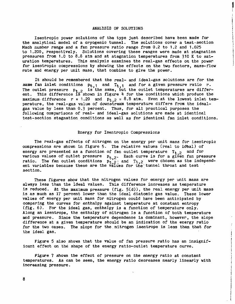
ANALYSIS OF SOLUTIONS
I s e n t r o p i c power s o l u t i o n s o f t h e type j u s t descr ibed have been made f o r the a n a l y t i c a l model o f a cryogenic tunne l . The s o l u t i o n s cover a t e s t - s e c t i o n Mach number range and a f a n p r e s s u r e r a t i o range from 0.2 t o 1.2 and 1.025 t o 1.200, r e spec t ive ly . So lu t ions cover ing these ranges were made a t s t a g n a t i o n p res su res from 1.0 t o 8.8 atm and a t s t a g n a t i o n tempera tures from 310 K t o satu r a t i o n temperatures. T h i s a n a l y s i s examines the real-gas effects on the powerf o r i s e n t r o p i c compressions by showing the effects on t h e two f a c t o r s , mass-flow rate and energy per u n i t mass, t h a t combine t o g i v e the power.
It should be remembered tha t t h e real- and ideal-gas s o l u t i o n s are f o r the same f a n i n l e t cond i t ions pt-1 and T t , l and for a g iven p r e s s u r e r a t i o r. The o u t l e t p ressure pt is the same, but t h e o u t l e t t empera tures are differe n t . T h i s d i f f e r e n c e 18 shown i n figure 4 f o r t h e c o n d i t i o n s which produce the maximum.difference r = 1.20 and p t 2 = 8.8 a t m . Even a t the lowest i n l e t t e m p e r a t u r e , the real-gas va lue of downstream temperature differs from the ideal-gas va lue by less than 0.3 percent . Thus, f o r a l l practical purposes t h e following comparisons o f real- and idea l -gas s o l u t i o n s are made a t i d e n t i c a l t e s t - s e c t i o n s t agna t ion cond i t ions as w e l l as f o r i d e n t i c a l f a n i n l e t cond i t ions .
Energy f o r I s e n t r o p i c Compressions
The rea l -gas effects o f n i t rogen on t h e energy per u n i t mass f o r i s e n t r o p i c compressions are shown i n figure 5. The r e l a t i v e va lues ( real t o i e a l ) o f energy are presented as a func t ion o f f a n o u t l e t temperature T t , 2 and f o r va r ious va lues o f o u t l e t p re s su re pt,2. Each curve is f o r a given f an p res su rer a t i o . The fan o u t l e t cond i t ions p t , 2 : and T t , 2 were chosen as t h e independ
’ e n t v a r i a b l e s because these are the va lues f o r t h e l t u n n e l t h r o a t and t e s t s e c t i o n .
These f i g u r e s show that the n i t rogen va lues f o r energy per u n i t mass are always less than the ideal va lues . T h i s d i f f e r e n c e i n c r e a s e s as temperature is reduced. A t the maximum pres su re ( f ig . 5 ( d ) ) , the real energy per uni t mass is as much as 17 percent lower than t h e ideal d ia tomic gas value. These lower va lues of energy per u n i t mass f o r n i t rogen could have been a n t i c i p a t e d by comparing t h e curves f o r en tha lpy a g a i n s t temperature .at cons t an t entropy ( f ig . 6). For t h e ideal gas, en tha lpy is a func t ion of temperature only. Along an i s en t rope , t he en tha lpy of n i t rogen I s a func t ion o f both temperature and-p res su re . S ince the temperature dependence is dominant, however, t h e s loped i f f e r e n c e a t a given temperature should be an i n d i c a t i o n o f t h e energy r a t i o f o r the two cases. The s lope f o r the n i t rogen i s e n t r o p e is less than tha t f o r t h e ideal gas.
Figure 5 also shows t h a t t h e va lue o f fan p re s su re r a t i o has an i n s i g n i f i c a n t effect on the shape of t h e energy r a t i o - o u t l e t temperature curve.
Figure 7 shows t h e effect o f pressure on the energy ra t io a t cons t an t temperatures. A s can be seen, t he energy r a t i o decreases n e a r l y l i n e a r l y wi th inc reas ing p res su re .
8

Real-Gas Effects on T u n n e l Mass Flow
The r e l a t i v e va lues (real t o ideal) of the tunnel mass f l o w are shown i n f i g u r e 8 as a func t ion of s t agna t ion temperature f o r va r ious va lues of stagnat i o n pressure . A s mentioned previous ly (fig. 41, the o u t l e t s t agna t ion temperatures were so nea r the same value f o r the real- and ideal-gas cases tha t these comparisons are a t e s s e n t i a l l y the' same throat condi t ions . Each curve is for a given t h r o a t Mach number.
As s t agna t ion temperature is reduced, the mass-flow rates f o r n i t rogen become inc reas ing ly g r e a t e r than those f o r an ideal diatomic gas. A t the maximum p re s su re ( f ig . 8 ( d ) ) , the n i t rogen mass-flow rate f o r MTH ~ 0 . 2 0 and the minimum temperature is about 9.5 percent greater than the ideal-gas mass-flow rate. For Mm = 1.0, the real mass flow is only about 7.0 percent greater due t o the s a t u r a t i o n temperature being higher than for the 0.2 case. The s h a p e . of the mass-flow-temperature curve is r e l a t i v e l y i n s e n s i t i v e t o the throat Mach number.
Power f o r I s e n t r o p i c Compressions
The real-gas effects on the power requi red f o r i s e n t r o p i c compressions are shown i n f i g u r e 9. The r e l a t i v e power va lues are shown as a func t ion of o u t l e t o r t h r o a t s t agna t ion temperature f o r va r ious va lues of s t agna t ion pressure . These r e l a t i v e va lues are a combination of t he r e l a t i v e e n e r g y . r a t i o s and the r e l a t i v e mass-flow r a t i o s . The power va lues f o r the real gas are i n gene ra l lower than those f o r t he ideal gas . A t t he maximum pressure ( f ig . 9 ( d ) ) and minimum temperature , t h i s reduct ion i n t he power requi red is about 9.5 percentf o r MTS = 0.2 ( r = 1.025) and about 7.5 percent f o r MTS = 1.2 (r = 1.2) . The shape of t h i s power-ratio-temperature curve is e s s e n t i a l l y independent of the pressure r a t i o and/or Mach number. This independence is t o be expected s ince the energy-ratio-temperature curve and the mass flow-temperature curve were e s s e n t i a l l y independent of the p res su re r a t i o and Mach number, r epec t ive ly . These power reduct ions due t o rea l -gas effects are, of course, i n a d d i t i o n t o the large power reduct ions which r e s u l t from opera t ing a t cryogenic temperature ( f ig . 1 ) .
APPROXIMATE METHODS
For the engineer ing design of systems which u t i l i z e n i t rogen , use of the complete c a l c u l a t i o n procedures of t h i s r e p o r t t o inc lude the real-gas effects on power c a l c u l a t i o n s would be very cumbersome. Therefore , some approximatemethods are now considered.
Energy P e r Unit Mass
The fol lowing two equat ions are approximations f o r the energy requi red t o compress a u n i t mass of real gas i s e n t r o p i c a l l y :
9

- 1 \ I
Equation (4) is t h e energy per u n i t mass por t ion - o f t he power equation giveni n r e fe rence 9. It is a r e s u l t o f t h e energy equat ion
and the assumptions t h a t t h e pressure-temperature r e l a t i o n s h i p f o r t h e ideal gas remains v a l i d
-Y p = TY-' (Cons tan t )
and t h a t Z v a r i e s l i n e a r l y wi th Pressure a long t h e i s e n t r o p e
Z = ( a + bpIS
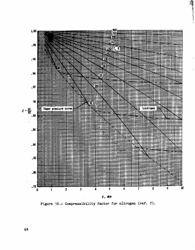
Equation (5) is der ived wi th t h e same c o n s i d e r a t i o n s , but Z i s assumed t o be cons tan t along an i s e n t r o p e . The da ta presented i n f i g u r e 10 i n d i c a t e t h a t t h i s is a reasonably good assumption.
Reference 9 i n d i c a t e s t h e actual va lues of s p e c i f i c heat r a t i o y f o r t h e condi t ions p r i o r t o compression should be u t i l i z e d i n these equat ions . However, i n r e fe rence 5, t h e i s e n t r o p i c expansion c o e f f i c i e n t s f o r n i t rogen were found t o remain near t o t h e ideal diatomic gas va lue of 1.4. I n a d d i t i o n , f o r t h i s study, use of t h e ideal va lue of I .4 gave more a c c u r a t e r e s u l t s over t h e range of condi t ions considered he re in than d i d use o f t h e a c t u a l va lue of y . For equation (51, t he use of e i t h e r Z t , o r Z g ives about t h e same degree of accuracy. For t h i s r e p o r t , Z t ,2 is use8;
Figure 11 shows a comparison of t h e s e approximate equa t ions wi th t h e exac t real-gas s o l u t i o n s . Both of t h e approximate s o l u t i o n s are wi th in 0.5 percentof t h e exac t va lues . Although equat ion ( 4 ) g i v e s e x c e l l e n t va lues f o r t h e energy pe r u n i t mass, it is unnecessar i ly complex f o r t h e range of cond i t ions considered he re in . Simply mul t ip ly ing t h e ideal va lues by the compress ib i l i t yf a c t o r Z t , 2 g i v e s r e s u l t s which are equa l ly a c c u r a t e .
10

~ . . . , .. ... .
Mass Flow
. . 'The mass flow per unit area is m = pV. This equation may be rewritten
in the following form:
The ratio of the real-gas mass flow mr to the ideal-gas mass flow hi at a given Mach number would be
If p = pa(Constant) is approximately valid for the real gas, and a remains near 1.4 (ref. 51, then
= 1.0 (from ref. 5 ) . With these considerations, S f
The accuracy of this simple approximation is illustrated in figure 12. For the range of conditions considered in this report, this approximation is accurate to about 0.5 percent.
Power
5- -K,then pr = &. Figure 13 illustratesIf - = Zt,2 and ir -
Ei mi the accuracy of this simple approximation. For the range of conditions considered herein,.the accuracy is within about 0.5 percent.
11

1 The r e s u l t s j u s t presented i n d i c a t e tha t s imple c o r r e c t i o n s t o the ideal- I
gas values of mass flow, compression energy, and compression power g ive accu1rate va lues f o r the real-gas case. i 11
CONCLUSIONS i
I n t h i s r e p o r t , an a n a l y s i s has been made of the real-gas effects of n i t r o gen on the power requi red f o r steady-flow i s e n t r o p i c compressions. The compress i o n s are assumed t o occur a t t he fan of a t r a n s o n i c cryogenic wind tunnel . The a n a l y t i c model tunnel was assumed t o ope ra t e a t s t agna t ion temperatures from 310 K t o s a t u r a t i o n and a t s t agna t ion p res su res from 1.0 t o 8.8 atm. The resu l t s of t h i s a n l y s i s l e d t o t he fol lowing conclusions:
1 . The energy t o compress a u n i t mass of n i t rogen a t cryogenic temperat u r e s is less than t h a t r equ i r ed f o r t he idea l gas . For t he maximum pressure-minimum temperature cond i t ions , t h i s reduct ion i n energy is on the order of 14 t o 17 percent .
2. Tunnel mass flow at a given Mach number is higher f o r cryogenic n i t r o gen than f o r t he ideal gas.
3. The power f o r i s e n t r o p i c compressions of cryogenic n i t rogen is a l s o less than t h a t requi red f o r t he i d e a l gas. A t t he maximum-pressure-minimumtemperature condi tons , t h i s reduct ion i n power is on the order of 7.5 t o 9.5 percent . The power decrease is less than the energy decrease because of the inc rease i n mass flow.
rr
4. Simple compress ib i l i t y f a c t o r c o r r e c t i o n s t o t he ideal va lues of mass flow, energy, and power g ive very accu ra t e estimates of the rea l -gas va lues .
Langley Research Center National Aeronautics and Space Administration Hampton, VA 23665 January 18, 1977
12
i b

APPENDIX A
TUNNEL THROAT CONDITIONS - REAL-GAS CALCULATIONS
F igure 14 con ta ins a flow chart o f t he p a r t o f t h e program t h a t makes the real-gas c a l c u l a t i o n s of the t h r o a t cond i t ions . The v a r i a b l e s r equ i r edf o r t h i s p a r t o f t he program are shown a t the top o f t he chart . A step-by-s t e p d e s c r i p t i o n of t h e c a l c u l a t i o n s t h a t occur a t each block o f t h e flow chart follows. All v a r i a b l e s should be assumed t o ' be rea l -gas v a r i a b l e s except those s p e c i f i c a l l y i d e n t i f i e d as ideal ( s u b s c r i p t i).
Step 1
Step 2
S tep 3
Step 4
Step 5
S tep 6
Step 7
S tep 8
S tep 9
S tep 10
Subrout ine PROP from the Nat iona l Bureau o f S tandards (NBS) program is used t o c a l c u l a t e t he s t a g n a t i o n en tha lpy ht,2 and en t ropy St ,12.
An i n i t i a l guess f o r t h e s t a t i c c o n d i t i o n s (pi, Pi, and Ti) is made by us ing the appropr i a t e ideal-gas equat ions .
The real-gas va lue o f s t a t i c temperature T i s i n i t i a l i z e d to t h e ideal va lue Ti and T i s e s t a b l i s h e d as t h e i t e r a t i v e v a r i a b l e i n o rde r t o f o r c e t h e s o l u t i o n s t o converge on t h e des i r ed MTH.
Function DSFND i t e r a t i v e l y solv'es f o r P from the en t ropy equat i o n St,2 = S ( P , T ) .
Subrout ine PROP g i v e s va lues f o r s t a t i c p re s su re p and s t a t i c en tha lpy h by us ing T and P from steps 3 and 4 , r e s p e c t i v e l y .
If t h e s t a t i c temperature T and s t a t i c p res su re p are co inc iden t w i t h a po in t on t h e vapor p re s su re curve or i f t hey l2e i n t h e l i q u i dreg ion , t h e s o l u t i o n is t e rmina ted .
Subrout ine VSND (NBS program) c a l c u l a t e s t h e v e l o c i t y o f sound c w i t h T and P a s - i n p u t s .
Subrout ine RVCAL c a l c u l a t e s t h e v e l o c i t y and Mach number from these .equations :
M = -V C
The mass-flow ra te per u n i t area is now c a l c u l a t e d
In = P V
The c a l c u l a t e d Mach number M i s checked t o see w h e t h e r ' i t i s wi th in 0.00001 of t h e des i r ed M . I f i t is , t h e s o l u t i o n f o r t h e t h r o a t cond i t ions is c6mplete anZHthe mass-flow rate is p r in t ed o u t .
13

A P P E N D I X A
Step 1 1 If the Mach convergence is not s a t i s f a c t o r y , subrout ine TCHANG f i n d s t he s lope of t h e temperature Mach number curve A T / A M f o r a cons tan t entropy St,2. A l i n e a r adjustment is made t o the s ta t ic temperat u r e T as requi red for Mach convergence.
Step 12 This ad jus t ed T is re turned t o s t e p 3 f o r the next i t e r a t i o n , and s t e p s 3 t o 12 are repeated u n t i l t h e Mach copvergence c r i t e r i o n is met a t step 10.
14

- .. ,. , . -...,,.,..--...-, ... . . , . ., . , ,
APPENDIX 'B
FAN CALCULATIONS - REAL G A S
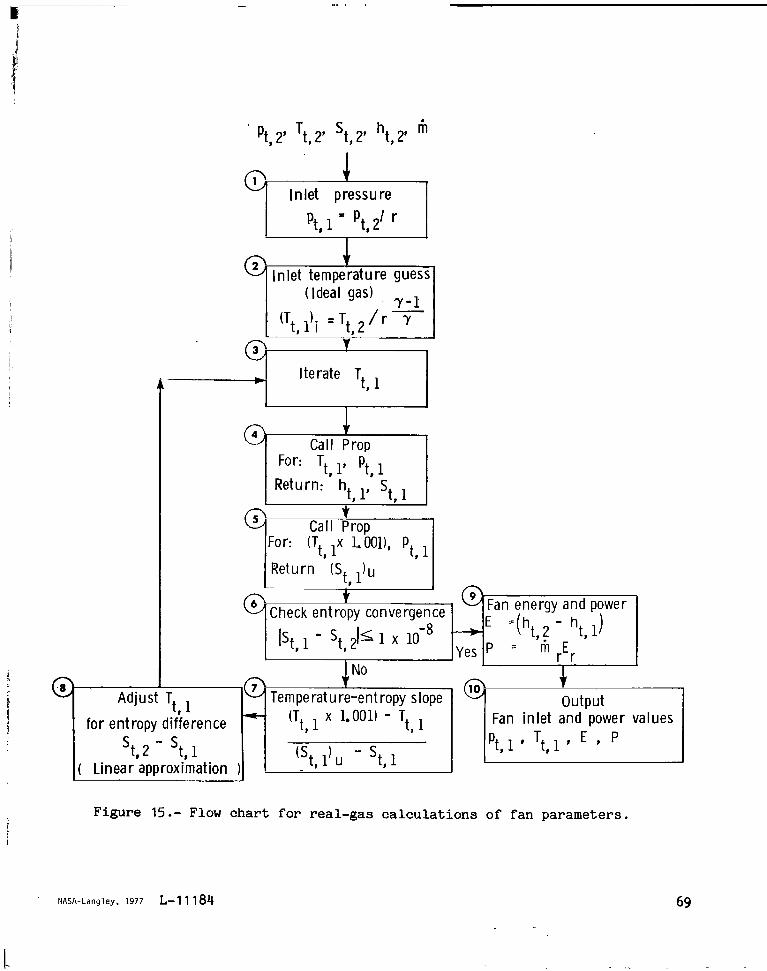
Presented i n figure 15 is a flow chart o f t he p a r t o f t he program t h a t c a l c u l a t e s t h e fan cond i t ions f o r t he rea l -gas ( n i t r o g e n ) case. The object i v e s of t h i s p a r t o f t h e program are t o o b t a i n an i s e n t r o p i c s o l u t i o n f o r t h e upstream s t a g n a t i o n q u a n t i t i e s pt and T t and then t o c a l c u l a t e t h e energy per u n i t mass E and the pbwer P r e t u i r e d f o r t h e compression. The downstream cond i t ions pt 2, Tt , St 2 , and Rt t h e fan p res su rer a t i o r , and t h e tunnel masslflow r&e m 'are r e q u i r ea' as i n p u t s t o t h i s p a r t of the program. The following i s a step-by-step d e s c r i p t i o n o f t h e calc u l a t i o n s t h a t occur a t each block o f the flow chart. Again, a l l v a r i a b l e s should be assumed t o be real-gas v a r i a b l e s except t hose s p e c i f i c a l l y i d e n t i f i e d as i d e a l ( s u b s c r i p t i).
Step 1 The fan i n l e t p re s su re i s c a l c u l a t e d d i r e c t l y as shown. Note t h a t P t 1 and p t , 2 have t h e same va lues f o r both t h e real- and idealga6 cases.
S tep 2 An i n i t i a l guess f o r t h e fan i n l e t temperature (Tt, 1) is made using the ideal-gas equat ion .
S tep 3 T+ is set up f o r i t e r a t i o n i n o rde r t o f o r c e the upstreame i G o p y St, t o be t h e same as t h e downstream entropy St,2 ( see s t e p 6 ) .
Step 4 Subrout ine PROP i s called w i t h p t , l and T t , l t o g i v e va lues f o r t h e upstream entha lpy ht , l and en t ropy S t , l *
S tep 5 The upstream temperature i s increased by a f a c t o r of 1.001 and i s used i n sub rou t ine PROP w i t h p
t , 1 t o g i v e another po in t of t h e
entropy-temperature curve (st ,1)n
S tep 6 A comparison of S t , l and St is made t o see whether these two e n t r o p i e s agree t o wi th in 1 x 101-8.
Step 7 If t h e two e n t r o p i e s have not converged s u f f i c i e n t l y , a temperature-entropy s lope i s c a l c u l a t e d from the informat ion o f s t e p s 4 and 5.
S t ep 8 This temperature-entropy s lope is used t o a d j u s t T t , l t o account f o r the d i f f e r e n c e i n the i n l e t and o u t l e t e n t r o p i e s S t , 2 - S t , l , and $he ad jus t ed T t , l is re tu rned t o s t e p 3 f o r the next i t e r a t i o n .
S t ep 9 When the convergence cri teria of s t e p 6 are f i n a l l y satisfied, the energy 'and power are c a l c u l a t e d .
S t e p 10 The s o l u t i o n is complete, and the f an i n l e t c o n d i t i o n s and powerva lues are s t o r e d f o r u t i l i z a t i o n i n o t h e r p a r t s of t h e program.
15
-2

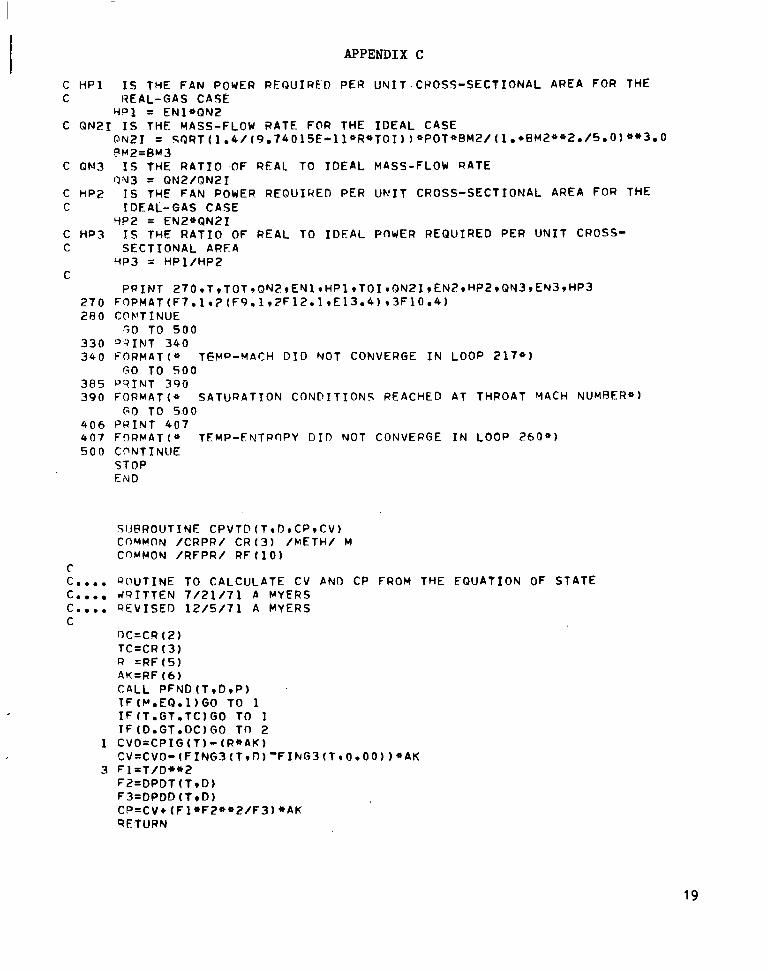
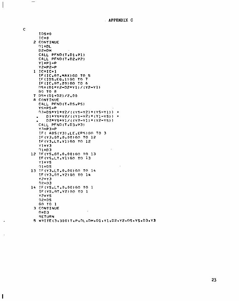
APPENDIX C
PROGRAM LISTING AND SAMPLE OUTPUT
Presented here is a listing of the program t h a t w a s developed i n order t o c a l c u l a t e t h e power and energy requi red t o compress n i t rogen and t h e ideal diatomic gas i s e n t r o p i c a l l y . This program is a modi f ica t ion of those of r e f e r ences 5 and 7. I n add i t ion , a sample output is presented .
Program L i s t i n g
PROGRAM N ~ P O W E R ( I N P U T I O U T P U T , T A P E S = I N P ~ J T ~ T A P E ~ = O U T P U T ) CALL DATA N 2
C THIS PQOGRAM CALCULATES THE POWER PEQUIREMENTS F O R ISENTROPIC C COMPPFSSIOYS OF BOTH NITROGEN AND AN I D E A L D I A T O V I C GAS C
QEAD 1001 NC 1 0 0 F O R M A T (15)
C C TBESE POWER REOU1REYE”T.S ARE CALCULATED FOR A S P E C I F I E D NUMBER OF C CASES ( N C ) r EACH O F WHICH INVOLVES KNOWN VALUES FOR THE TEST-SECTION C MACH NUMBER (BM2)9 FAN OUTLET PRESSURE ( P O T ) * AND THE R A T I O O F FAN C OUTLET TO I N L E T PRESSURE (PR41 C C THE POWER AND MASS-FLOW RATE CALCULATIONS INVOLVE CROSS-SECTIONAL C PREAS WHICH CORRESPOND TO THE THROPT AREA OF THE TEST SECTION ‘ C
DO 5 0 0 L = 1,NC QEAD 2009 POTI PR49 R M 2
2 0 0 FORMAT (3F10 .0 ) P Q I N T 2 1 0 1 R M 2 r P R 4 r POTI (POT’/PR4)
2 1 0 FORMAT ( l H l r 3 2 X i * E N E P G Y PND POWER REQUIREMENTS FOR FAN-DRIVEN C R Y 0 l G E N I C WIYD TUNNEL* /~~XI *JSENTROPIC COMPRETSION IN NITROGEN*///ZX,* ?TEST-SECTION M A C V NUMPER =* rF5 .2 /PX**FAN PRESSURE R A T I O * I ~ X * * = + ~ F ~ 3 . 4 r “ * / 2 X * * F A N . PRFSSUREI O U T L E T * I ~ X I * = ~ * F ~ O ~ I * ATM*/2Xq*FAN PRE ~ S S U R E I - I N L E T + ~ ~ Y I * = * * F ~ ~ ~ I *ATM* / / /ZX* *E = FAN ENERGY*/ZX**P = FAN 5 P O W E R * / / / ~ ~ X I ~ ~ ( * - * ) ~ ~ R F A L GAS0916G A S * I ~ ~ ( * - * ) ~ * X * ~ ~ ( * - * ) I * I ~ E A L ~ ( * - * ) I ~ X ~ ~ ( * - * ) I * R E A L / I D ~ A LV A L U E S * ~ ~ ( * - * ) / ~ X ~ * T T ~ I N * * ~ X * ~ ( * T T I O U T ~ ~ ~ ~ X I * M D O T * ~ ~ X ~ * E / H A S S * I ~ X ~ * P / A R ~ A * I ~ X ) ~ ~ X ~ * M ~ O T * I S X I * E / M A S S * I ~ X ~ * A P / A R E ~ * / ~ X . * K * ~ ~ X * ~ ( * K * I ~ X * * K G M I S - M ~ ~ , ~ X ? * J / K G ~ * I ~ X I * J / S - M ~ ~ I ~ X ) / )_
c C FOR EACH CASE* THE CALCULATIONS ARE PERFORMED FOP EACH OF c INCREMENTALLY DECREASING VALUES OF FAN OUTLET TEFPERATUQE (.TOT) ~JNTIL C SATURATION CONDITIOYS ARE QEACHED C
DO 280 1-1150 I F ( 1 .GT. 2 0 ) GO TO 2 0 5 TOT= 320. - I * 1 0 GO TO 2 0 6 r
205 TOT = 120. - ( 1 - 2 0 ) * 5
16

APPENDIX c
C C THE L I Q U I D REGION CONDITION I S REACHED WHEN THE TEMPERATURE FALLS C BELOW THAT O F THE C R I T I C A L P O I N T * AND THE PRESSURE RISES ABOVE THE C CORRESPONDING SATURATION PRESSURE (PSAT) C C THE C Q I T I C A L POINT FOR NITROGEN IS AT PRESSURE = 3305 ATM AND AT C TEMPERATURE = 126 DEGREES K E L V I N C C WHEN T H I S S I T U A T I O N OCCUPS* THEN THE NEXT CASE MUST BE CONSIDERED C
2 0 6 PSAT =3305 IF (TOT oLTo 126) PSAT = V P N ( T 0 T )IF (POT o G T o PSAT) GO TO 385
C C USING THE KNOWN PROPERTIES O F NITROGEN9 THE DENSITY ( D O T ) * ENTHALPY C (HOT), AND ENTROPY ( S O T ) c AT THE OUTLET O F THE FANe C A Y RE CALCULATED C
C A L L P R O P ( T O T c P O T ~ D O T c l r H O T ~ S 0 T ~ U ) C C STATIC CONDITIONS AT THE TUNNEL THROAT WHICH CORRESPOND TO THE DESIRED C THROAT VACH NUMBER ARE ESTIMATED BY ASSUMING ISENTROPIC FLOW OF IOEAL C GAS FROM FAN OUTLET TO THROAT c . C T I S THE TEMPERATURE C D IS THE DENSITY C P IS THE PRESSURE C
A M 3 = R M 2 IF ( B M 3 o G f o l o O ) RM2=100 T = 1 0 / ( 1 0 + B H 2 * + 2 . / 5 0 ) ~ T O T D = DOT* (T /TOT)* *Po5 P = P O t ~ ( T / t O f ) ~ * 3 0 5
C c ANOTHER TEST FOR SATURATION CONDITIONS C
PSAT = 3305 IF (ToLT .126 . ) PSAT = V P N ( T ) I F ( P oGTo PSAT) GO T O 3 8 5
C c THF T Y R O A T TEMPERATURF IS VAPIED C SOLUTION CONVERGES O N THE D E S I R E D C C H IS THE ENTHALPY c S 15 TYE FWTROPY C C BMACH I S THE T R I A L M A C H NUMRFR c VEL IS THF FLOW VELOCITY
U N T I L THE RFAL-GAS ISENTROPIC THROAT M A C H NUMBER
c BN2 IS THE MASS-FLOW RAT� FOR THE REAL-GAS CASE C
00 217 K = l e 1 0 0 D = DSFND(SOT*T,D) CALL PROP(T*PIDIZIHISIU)
17

APPENDIX C
C C ANOTHER TEST FOR SATURATION CONDITIONS C
DSAT = 33.5 I F ( T . L T * 1 2 6 a ) PSAT = VPN(T) I F ( P .GT* PSAT) GO TO 385 CALL VSND~T~PIDIPIW) CALL MQRCAL(HOT,HID ,T IWIBMACH,QN~,REY) CALL WVCAL(HOT,H,W,RMACHIVEL) Q " 4 2 ~28.0134 *D*VEL I F (ABS(BMACH-BM2)-.00001) 2189 2 1 8 9 216
216 IF (K.EQ.100) GO TO 330 CALL T C H A N G ( f l M A C H * R M Z r T * D I S O T , H O f )
217 COMTIYIJE C C THESE ARE THE FAN I N L E T PRESSURE ( P ) AND AN ESTIMATE OF THE FAN C I N L E T TEMPERATURE ( T I c
2 1 R P = POT/PR4 T = TOT/PR4**.2057
C C NO\J THE PROGRAM VARIES FAN I N L E T TEMPERATURE SO THAT THE I N L E T C ENTR9PY CONVERGES TO THF OUTLET AND/OR TEST-SECTION VALUE ( ISENTROPIC C COMPRESSION) C C TIJ I S THE INCREMENTFD TEMPERATURE C SU TS THE CCWRESPONDINGLY INCREMENTED ENTROPY C
DO 2 6 0 J=1,100 TU = 1.001 * T CALL PRdP(T9P,D* l rH*S ,U) CPLL PROP(TU~P9DU919HU,SU1U) I F (ABS(S-SOT) d1.E-08 * SOT) 2 6 5 9 2 6 5 9 2 5 6
256 T= T + ( T U - T ) / ( S U - S ) * (SOT-S) 06 I F ( 3 .EQ. 1 0 0 ) GO TO 4 0 6
260 CCNTINUE C c NOW THAT ALL OF THE NFCESSARY CONDITIONS F O R THE TUNNEL HAVE BEEN C DFTFRMINED9 THE POWER REQUIREVENTS CAN RE CALCULATED AND PRINTED @UT C ! C EN1 IS THE ENERGY REQUIREMENT PER U N I T MASS F O R THE REAL-GAS CASF
265 E Y 1 = 3Sa697* (HOT-H) C R IS THF NITROGEN G A S CONSTANT9 I N J/KGM-K
R = 296 .791 C TO1 I S THE OUTLET TFMPERATUPF FOR THE IDEAL-GAS CASE
TO I = P94** .2857*T c EN2 IS THE ENERGY REQUIREMENT PER U N I T MASS FOR THE IDEAL-GAS CASE
EY2 = 3 0 5 * R * T * ( P R 4 * o a 2 8 5 7 - 1 . 0 ) C EN3 IS THE RATIO OF REAL TO IDEAL ENERGY PER U N I T MASS REQUIREMEhT
�'\I3 = E Y l / E N P .
18
APPENDIX C
C HP1 I S THE FAN POWER REQUIRED PER UNIT.CROSS-SECTIONAL AREA FOR THE C HEAL-GAS CASE
Y o 1 = ENl*QNZ C Q N Z I I S THE MASS-FLOW RATE FCIR THE I D E A L CASE
C QN3
C HPZ C
C HP3 C
C
2 7 0 2 R 0
330 34 0
3 8 5 390
406 4 0 7 5 0 0
C c.... c.... c.... C
1
3
ON21 = S ~ R T ( ~ ~ ~ / ~ ~ ~ ~ ~ ~ ~ ~ E ~ ~ ~ ~ R ~ ~ ~ ~ ) ) * P O T * ~ M ~ / ( ~ ~ + ~ M ~ * * ~ O / ~ O O ~ * * ~ O O F W Z = B M ~
I S THE R A T I O . O F REAL TO I D E A L MASS-FLOW RATE O M 3 = Q N 2 / Q N 2 I IS THE FAN POWER REOUIHED PER U N I T CROSS-SECTIONAL AREA FOR THE IDEAL-GAS CASE
YP2 = EN2*QN2I IS THE R A T I O O F REAL TO I D E A L POWER REQUIRED PER U N I T CROSS-SECTIONAL AREA
HP3 = H P l / H P Z
PRINT 2 7 0 r T ~ T O T ~ Q N 2 r E N l r H P l t T O I ~ Q N 2 1 r E N ~ t H P 2 r Q N 3 r E N 3 t H P ~ ~ ~ P M A T ( F 7 . l r ? ( F 9 o l r Z F l ~ o l r & ~ ~ 0 4 ~ ~ 3 F l O o 4 ) COWTINUE ,50 TO 5 0 0
D:?INT 3 4 0 FORMAT(* TEMP-MACH D I D NOT CONVERGE I N LOOP 2 1 7 " ) GO T O 5 0 0
P ? I N T 390 FORMAT(* SATURATION CONDITIONS REACHED A T THROAT M A C H NUMBER*) GO T O 5.00
PQINT 407 FORMAT(* TEMP-ENTPnPY D I D N O T CONVERGE I N LOOP 260") CONTINUE STOP END
C~J@ROUTINECPVTF ( T r D r C P r C V ) COMMON /CRPR/ C R ( 3 ) /METH/ M COMMON /RFPR/ R F ( 1 0 )
QOUTINE TO CALCULATE C V AND CP F R O M THE EQUATION OF STATE d Q I T T E N 7 / 2 1 / 7 1 A MYERS QEVISED 1 2 / 5 / 7 1 A MYERS
D C = C R (2) TC=CR [ 3 ) R = R F ( 5 ) AK=PF (6) C 4 L L P F N D ( T r 0 r P ) I F ( P o E Q o 1 ) G O TO 1 I F ( 1 o G T o T C ) G O TO 1 l F ( D o G T o 0 C ) G O TO 2 CVO=CPIG(T) - (R*AK) C V = C V O - ( F I N G 3 ( T r D ) ' F I N G 3 ( T I O . O O ) ) o A K F l = T / D * * t F Z = D P D T ( T r D ) F3=DPDD(TrD) C P = C V + ( F l * F 2 * * 2 / F 3 ) * A K 9E-TURN
19

APPENDIX C
2 !'T=0.1 T 1=T*DT T 2=T-0 T CALL L P R O P ( T l r P 1 , D i l r H ~ S ~ U l ) CALL L P R O P ( T ~ ~ P ~ ~ F , ~ , H I S ~ U ~ ) CV=(UL-U2) / (2onO*DT) GO TO 3 EWD
SUBROUTINE DATANZ COMMON /CEOS/G(41) / C V P N / G V ( I l I / C I G C P / G I ( 9 ! / C S L / C L ( 7 ) /CSV/CV(7 ) . /CRPR/CR(J) /CTEVP/CT(8 ) /RFPR/RF(10) /YETH/ M
C C.... I F THE PROPERTIES O F NITROGEN ARE TO BE CALCULATEQI, A C A L L TO T H I S C o o . . SUBROUTINE MtJST RE THE F I R S T C A L L STATEMENT I N THE MAIN PROGRAM C Coo. . THE COMMON BLOCKS I N I T I A L I Z E D IN T H I S ROUTINE HOLD THE FOLLOWING C.... INFORMATION C C /CEOS/ G ( 4 1 ) COEFFICIENTS OF THE EQUATION O F STATE C C /CIGCP/ C I G ( 9 ) COEFFICIENTS OF THE IDFAL-GAS HEAT CAPACITY EQUATION C C /CVPN/ G G ( 1 1 ) COEFFICIENTS OF THE VAPOR PRESSURE EQUATION C CC
/CRPR/ C R ( 3 ) THE C R I T I C A L PROPERTIES I N THE SAME U N I T S AS THEEQUPTION OF STATE t
C C R ( l ) = C R I T I C A L PRESSURE C C R ( Z I = C R I T I C A L DENSITY C C R ( 3 ) = C R I T I C A L TEMPERATURE C C /CSL/ SL ( 7 ) COEFFICIENTS OF EQUATION USED TO APPROXIMATE C THE: SATURATED L I Q U I D DENSITY AS A FUNCTION OF C TEPPERATURE C C C /RFPR/ R F ( 1 0 ) REFERENCE PROPERTIES C RF t l I -REFERENCE ENTHALPY A T TEMPERATURE TOH C R F ( 2 ) t R F F E R E N C E ENTROPY AT TEMPERATURE TOS C RF(3)=TEMPERATURE TOH C RF(4)=TEMPERATURE TOS -C RF(S)=GAS CONSTANT I N U N I T S OF EQUATION OF STATE R C RF(6)=CONVERSION FACTOR TO CHANGE U N I T S OF C THE FQUATION O F STATE TO DESIRED ENERGY U N I T S C RF(7)=MOLECULAR WEIGHT C R F ( B ) = T R I P L E POINT TEMPERATURE-C R F ( 9 ) NOT USED-C R F ( 1 0 ) NOT USED C C /METH/ M I N D I C A T E S METHOD TO BE USED I N THE CALCULATION C O F L I Q U I D PROPERTIES C M = l INDICATES ISOTHERM INTEGRATION THROUGH THE DOME C M = 2 INDICATES THE USE OF THE CLAPEYRON EQUATION C THROUGH THE DOME
20

APPENDIX C
0.136224769272U270-02 0.1070324699085910 00
-0.243~807218714130 0 1 Oe3410074493764700 0 2
-0.4223743094661670 04 0.1050986002464940-03
-0,112594i3265220A10-01 0.1426007892709070-03 O.lA4h98501609007D 05 Oef?l1140082588776D-07 Oe23301164503,80060-02
-0e5077525863509860 0 0 O.PRS0278819312140-04
-0.1136567641153640-02 -0.7074302735405750 0 0
0.7517066488526800-04 -0. l l lh141195374240-05
Oe36A79h5627334950~03 -0.20r317691347729~-05 -0.1697174447559490 05 -0.1197192400441920 06 -0.9752182720382810 02
0.5546397131518230 05 -0~1799204SO4434700 0 0 -0.2565829260771640 0 1 -0.4137077150907890~03 -0.256245415300?93D 0 0 -0.124222373740063DcO6
0.103556535A401650-04 -0,5386991665583030-09 -0.7574154128395960-08
0.5853671720695210-07 -0.560000000000000D-02
0.03944094440 04 CV(Z)=-O.lR900*5259D 04 GV(3)=-0.72822291650 0 1 G V ( 4 ) = O 000 G V ( 5 9 = 0.5556063R25.D-03 5V(6)=-0.59445446620-05 GV(7)= 0.27154339320-07 GV(8)=-0e4R795359040-10 C i V ( 9 ) = 0.50953608240 0 3 G V ( l O ) = Oe1022850966D-01 G V ( 111= 0~195000000000000D 0 1 G T ( l ) = -0.7352104011572520 03 G I ( 2 ) = 0.3422399R04119780 02 61(3)= -0.5576492845676POD 0 0 GI ( 4 ) = 0.3504042283087560 0 1 C I ( 5 ) = -0.1733901850810050-04 GI ( 6 ) = ~,1766508497664630-07 G I ( 7 ) = -0.3568920335*43480-11 51 I R ) = 0.10053R722808P340 01 GI ( 9 ) = 0.3353406100000000 04 C L ( l ) = 0.1942440319220000 0 2 C L ( 2 ) = 0~570837481942000D 02 C L ( 3 ) = -0.243269850463000D 03
21

k
APPENDIX C
CL ( 4 ) = O.RR5168381502000D 03 '
CL(5)= - O m 1 6 3 9 3 6 7 9 7 7 3 4 0 0 0 0 04 C L ( 6 ) = O e 1 1 5 7 * 3 2 0 0 5 3 3 6 0 0 D 0 4 C L ( 7 ) = ' 0 . 1 0 1 8 2 2 0 9 R 3 2 7 0 0 0 0 0 1 c v ( 1 ) = 0 . 1 6 3 3 3 3 4 5 5 3 8 6 0 0 0 0 0 1 C V ( E ) = - 0 . 9 4 0 4 3 7 7 0 9 1 7 0 0 0 0 0 0 1 cv 13) = 0 . 2 1 8 5 2 7 4 6 0 2 6 6 0 0 0 0 02 c v ( 4 ) = - 0 . 1 0 2 6 9 7 4 3 7 6 3 7 0 0 0 0 03 c v 15) = 0 . 1 8 7 9 4 9 7 4 4 8 6 2 0 0 0 D 03 C V ( 6 ) = -0 .16*0243h7971000D 0 3 C V ( 7 ) = - 0 e 9 5 7 3 . 1 6 3 9 0 3 1 6 0 0 0 0 - 0 1 C Q (11 =33 .55500 C w ( 2 ) = l l . 2 1 0 0 CR (31 ~ 1 2 62 0 0 C T ( 1 ) = - 0 e 1 4 2 0 6 4 7 8 6 2 0 0 Q 0 0 0 ~ 0 2 C T ( 2 ) = 0 . 1 2 9 0 8 8 0 8 6 9 0 0 0 0 0 D - 0 1 C T ( 3 ) = 0.0 CT ( 4 ) = 0.0 C T ( 5 )= 0.0 CT ( 6 ) = 0.0 C T ( 7 ) = O m 0 C T ( 8 ) = 0.0 R F ( 1)= R e 6 6 9 D 0 3 Q F ( 2 ) = 1 9 1 * 5 0 2 P 0 0 QF( 3 )~ 2 9 8e 15DOO Q F ( 4 ) = 2 9 R e l S D O O H F ( 5 ) = 0 e 8 2 0 5 3 9 0 0 0 0 0 0 0 0 0 D ~ 0 1 R F ( 6 ) = 0 ~ 1 Q 1 3 2 7 A O O O O O @ @ O D0 3 R F ( 7 ) = 2 9 . 0 1 3 4 0 0 R F ( @ ) = 6 3 o 1 4 8 D O QFTURN �\ IO
SUBROUTINE DCALC(O,~~P,DL ,DH) DATA (YAX=30) OATA(EPS= leE-5 )
QOUTINE TO PFRFORH I T E R A T I V E SOLUTION O F THE EQUATION OF STATE
DL I S LOWER BOUND ON DENSITY DH I S UPPER ROUND ON DENSITY
THE DESIRED DENSITY MtJST L I E BETWEEN DL AND DH
ALGORITHM IS MODIFIEO VERSION OF
* A QUADRATIC FORMULA FOR F I N D I N G THE ROOT OF AN EQUATION* BY L I . G o CHAMBERS MATHEMATICS O F COMPUTATION V O L 25 YO 1 1 4 APRIL ( 1 9 7 1 )
MRITTEN 2 / 7 / 7 2 A MYERS
22
APPENDIX C
C I D S = O IC=O
2 C O N T I N U E 91= D L D2=DH C A L L P F N D ( T q D l r P 1 ) C A L L P F N D ( T * D E * P 2 ) Y l = P l - P Y 2 = P 2 - P
1 I C = I C + l I F ( I C . G T . M A X ) G O TO 5 I F ( I D S . E Q . 1 ) G O T O 7 I F ( I C . G T . E O ) G O T O 6 nS=(D10Y2-D2*Yl)/(Y2-Y1) GO T O 8
7 OS=(01+02)/2.00 R C O N T I N U E
C 4 L L P F N D ( T * D S * P S ) Y S = P S - P n3=DS*Yl*YZ/((YS-Y2)*(YS-Y1)) + . D l * Y S * Y 2 / ( ( Y l - Y 2 1 * ( Y l - Y S ) 1 +
Da*YS0Yl/((Y?-Yl)*(Y2-YS)) C A L L P F N D ( T * D 3 r P 3 ) Y 3 = P 3 - P I F ( A B S ( Y J ) . L E . E P S ) C O T O 3 I F ( Y 3 . G T . O . O O ) G O I F ( Y 3 o L T o Y l ) G O Y 1 = Y 3 3 l = D 3
12 T F ( Y S o G T . O . O O ) G @ IF ( Y S . L T . Y l ) G @ Y l = Y S r)l=DS
13 T F ( Y 3 . L T . O . O O ) G O I F ( Y 3 . G T . Y 2 ) G O Y 2 = Y 3 D ? = D 3
1 4 I F ( Y S o L T . O . O O ) G O I F ( Y S * G T o Y 2 ) 6 0 Y z = Y s !32=DS GO T O 1
3 C O N T I N U E O = D 3 Q E T U R N
TO 12 TO 12
TO 13 T O 13
T O 14 T O 1 4
TO 1 T O 1
5 Y ~ I T E ( ~ ~ ~ O O ) T I P ~ ~ L ~ D H ~ O ~ ~ Y ~ ~ D ~ * Y ~ * ~ S * Y S I ~ ~ * ~ ~
23

APPENDIX C
SVBROUTIWE D F N D ( T r P r D r K ) COMMON /RFPR/ R F ( 1 0 ) CnMYON /CRPR/CR(3)
C C.... YnUTINE TO CENER4TE T R I A L D E N S I T I E S F O R I T E R A T I V E S O L U f I O N OF C.... THE EQIJATION O F STATE FOR DENSITY G I V E N TEMPERATURE AND PRESSURE C C K = O I N D I C A T E S S INGLE PHASE P O I N T C Y =1 I N D I C A T E S T + P ARE F O R THE SATURATED L I Q U I D C K =2 I N D I C A T E S T + P ARF FOR THE SPTURATED VAPOR C C o o o e WRITTEN 2 / 1 0 / 7 2 A MYFRS C
IF((K~LE.~).ANDo(KoGEoO))GO TO 1 V P I T E ( 3 r 3 0 0 ) K
3 0 0 FORMAT(27H e** ERROR I N CALL DFND ****/I 9 K HUST EQUAL O r 11 OR 2 * r / r
0 0 K = * r I l O ) RFTURN
1 P C = C R ( l ) DC=CR (2 ) TC=CR(3) I F ( K o G T o 0 ) G O TO 5 I F ( T o G E o T C ) C O TO 2 VP=VPY(T) TF(PoLEoVP)G@ TO 3
4 DH=30100*0C OL=DSATL ( T 1 C 4 L L D C A L C ( D r T r P , D L r @ F ) QFTURN
3 DL=O DY=DSATV ( T ) CPLL DCA.LC ( DI TI PI D L r DH 1 RETURN-
24

APPENDIX C
2 DL=O DH=3o100*DC I F ( ( T o G T o 1 0 0 0 o 0 0 ) . A N D ~ ~ P o L l o 3 O O o O O ) ) D H = D C CALL DCALC(DITIP*DLIDH) RETURN
5 I F ( K o E O o 1 ) G O TO 4 GO TO 3 ' END
SURROUTINF: DPDTVP(T~PIDPDT) COMMON/CVPN/G(I l ) /CRPR/CR(3) COMMON /SCRH/ X ( 4 0 )
C Coo. . CALCULATE DP/DT FOP THE VAPOR PRESSURE EQUATION C Coo.. WRITTEN 7/22/71 A MYERS
i TC=CR ( 3 ) A = G (111
. T?=T*T T3=T*TZ T 4 =TOT 3 TS=T*T4 X ( 1 ) = - 1 0 0 0 / T 2 x ( 2 ) = o x ( 3 ) = 1 0 0 0 % ( 4 ) = 2 . 0 0 * T X ( 5 ) = 3 . 0 0 + T 2 X ( 6 ) = 4 o O O * T 3 Y ( 7 ) = 5 0 0 0 * T 4 X ( A 1 =6 0 O*T5 x ( ~ ) = I . ~ o / T Y ( 1 0 1 = (TC-1 ) ** (A-1.00) DPDT=O DQ 1 I = l r l O
1 WDT=DPDT*X ( 1 ) * G ( I )
* ( - A 1
,
DDDT=DPDT*P RETURN END
C C.... c.... c.... c C C C C
SIIRROUTTNE LPROPITIPIDTKTHISIU) COMMON /RFPR/ P F ( 1 0 ) CqMMON /METH/ M
QOUTINE TO CALCULATE THE PROPERTIES O F THE L I Q U I D 'J ' i i ITTEN 7 / 2 0 / 7 1 A MYERS REVISED 12/8/71 A MYERS
K =I IWJTIS T + D Y =2 INPUT IS T + P K =3 INPUT I S TI PI + D
TF(YoEOo2)GO TO 1 CALL VPROP ( T r P ID 9$I'H 9S I U ?FTIJRN
25
C

APPENDIX C
1 9 = P F ( 5 ) AK=RF (6) I F (K EQ. 11 CALL PFND ( T 9 0 9 P 1 TF(KoEQm2)CALL DFND(T*PIDIOI VD=VPN ( T ) CALL DFND(T,VP*DSV,Z) CALL VPROP(T,VPP*DSV,lrHSVISSVtUSVUSV) VSV=1.00/DSV CALL D F N D ( T I V P * D S L * l ) VSL=l.OO/DSL. CALL DPDTVP(TIVPIDPDT) HSL=HSV-T*DPDT*(VSV-VSL)*AK SSL=SSV+(HSL-HSV)/T ( J S L = U S V * ( H S L - H S V l - ( V P * ( V S L - V S V ) ) * A K DLD=ALOG ( D ) DLS = ALOGtDSL) F I D = R * D L D - F I N G l ( T * D ) F l S = R * D L S - F I N G l ( T v D S L ) F?D=FIN82(T ,n ) *R*T*DLD F ~ S = F I N G 2 ( T * D S L ) + R * T s D L S S=SSL- (F 10-F 1S 1 *AK ll=USL+((F2D-FZS)=T*(FlD-FlS))*AK Y=U + (P /D) *AK RETURN FVD
SlJRROUTINE M Q R C A L ( H O T I H * D , T , W I B M A C H I Q N ~ , R E Y ) C SUBROUTINE C A L M e Q , P E Y / M
VEL = SQRT ( 2 / . 0 2 8 0 1 3 4 * (HOT-H) SYACH = VEIL/W QN2 = 0*28.0’134*VEL**2/2.0 Dn=D* 0280 134 EMU = V I S C ( D D I T ) * I . E - O ~ QFY = 28.0134+D*BMACH*W/EMU RETURN EVD
26
1

I
,
APPENDIX C
C m e m . T u 1 5 ROUTINE CALCLILATES PPESSURE G I V E N TEMPERATURE AND DENSITY Cam.. F R O M THE EQUATION OF STATF C
R = Q F ( 5 1 T)?=D*D 03=D2*D r)4=D3*D r)S=D4+D 05=D5*D n 7 = ~ 6 * ~ DR=D7*D D9=@8*Dni 0 = ~ 9 * 1 ) 1711=DlO*D 0 12=D11*0 013=D129D TS=SQRT(T) T2=T*T T3=T2*T T4=T3*T GM=G ( 41 ) F = E X P ( G M 902) 9( 1 ) = D 2 9 T ;1( 2 ) = 0 2 * T S H ( 3)=0?e ( 4 ) = D 2 / T q( 5)=fl2/T2 R ( 6)=D3*T Y( 7 ) = D 3 a ( 8 ) = D 3 / T r j ( 9 ) = D 3 / T 2 5 ( 1 0 ) = 0 4 * T 9 ( 111 =04 9 ( 1 2 ) = 0 4 / T Y ( 1 3 ) = D 5 1 9 ( I 4 ) = D 6 / T i u ( 1 5 ) = D 6 / T 2 9 ( 1 6 ) = D 7 / T 3 ( 1 7 ) = D 8 / T R ( 1 8 ) = Q 8 / T 2 R ( 1 9 ) = 0 9 / T 2 q ( 2 0 ) = D 3 * F / T 2 H ( 2 11 =D3*F/T3Y (22 )=DS*F /T? H ( 2 3 ) = D 5 * F / T 4 H ( 2 4 ) = D 7 * F / T 2 B ( 2 5 ) = D 7 * F / T 3 9 ( 2 6 ) = D 9 * F / T 2 8 ( 2 7 ) = 0 9 * F / T 4 9 ( 2 8 ) = D l l * F / T 7 A ( 2 9 ) = 0 1 1 * F / T 3 Y (301 =D13*F /T2 9 ( 3 1 ) = D 1 3 * F / T 3 R ( 3 2 ) = D 1 3 * F / T 4 M = 3 2 P=O . DO 1 I = l r N
27

APPENDIX C
SLJBPOUTINE PROP(TIPIDIKIH~S~U) C 3 M M O Y /CRPR/ CR ( 3 ) /METHIM
C Coo.. GENERALIZED PROPERTY CALCULATOR C o o . . WRITTEN 7 / 2 0 / 7 1 A MYERS C o o o o PEVISED 1 2 / 1 6 / 7 1 A MYERS C C o o . . QOIJTINE CALCULATES PROPEPTIES FOR FOLLOWING INPlJT O F K C C K = l INPUT IS T + P RFTURNS 01 HI SI + U C Y = 2 IWPUT I S T + D RETURNS Pv HI SI + U C K=3 I W I J T I S T RETURNS PI 01 HI SI U FOR SATURATED VAPOR C u = 4 INPUT I S T RETIJRNS PI D e HI SI U F O R SATURATED L I Q U I D C Coco. NOTE: ALL REAL VARIABLES I N CALL STATEMENTS TO ROUTINES I N C T H I S PACKAGF MUST BE TYPE REAL*B (DOUBLE PRECIS ION) C Coo.. MOTE: THE F I R S T CALL STATEMENT I N THE USER*S MAIN PROGRAM MUST C BE TO 4 DATA I N I T I A L I Z A T I O N ROIJTINE C EXAMPLE: CALL DPTAN2 C Coo. . YOTE: THE METYCID OF PROPERTY CALCULATION IS DETERMINED 8 Y THE C C
VALUE O F H CONTAINED I N COMMON BLOCK /METH/M
C Y = 1 INDICATES PROPERTY CALCl lLATIQN TO BE CARRIED OUT R Y C CONTINUOUS INTEGRATION OF ISOTHERMS THROUGH THE TWO PHASE C REGION C M = 2 INDICATES PROPEQTY CALCULATION I S INTERR!lJPTED AT THE TWO C PHASE VAPOR ROCIPIDAPY AND THE CLAPEYRON RELATION WITH THE C V A P O R PRESSURE EQUATION I S USED TO CALClJLATE THE LATENT C HEAT. INTEGRATION O F ISOTHERMS I S CONTINUED A T THE C SATURATED L I Q I J I D RQULJDARY C
PC=CR (11 DC=CR(Z) TC=CR (31 I F ( ( K o ~ T . O ) . A N ~ o ( K o L T . 5 ) ) G O TO I i r 1 ~ITF ( 3 i 3 0 0 1 K
- 3 0 0 FORMAT(27H *** ERDnP I N C A L L PROP ***,/I 0 9 K MllST FOIJAL 112131 OR 4 * 1 / r . 0 0 K = * r I 1 0 )
RETURN 1 I F ( K o L T o 3 ) G O TO 3
IF (T .LEoTC)GO T O 2 t
q R I T E ( 3 1 3 0 1 1 T 3 0 1 .F!lRYAT(27H'*++ FPROR I N C A L L PROP +*** / I
9 SPTIIRATTON PROPERTIES HAVE REEN REQUESTED*r/r 0 0 FnP A TEMPFRATURE THAT EXCEEDS CRITICAL* I / I. 0 T = *1F1!505)

APPENDIX c
3 P = V P N ( T ) I F ( K o E Q o 3 ) C A L L DFND(T,Prf ’*2) IF ( K .EO. 4 ) C A L L D F N D (1 P * DI 1) 63 T O 6
3 I F ( K o G T o 1 ) G O T O 7 C ~ L L D F N D ( T ~ P , D ~ o ) I F ( T e G T . T C ) G O T O S
4 T F ( D . G T * D C ) G O T O 6 5 C A L L V P R O P ( T r P r D r 3 r H r S r I ) )
7 F T U Q N 6 TF(M.EO.1)GO T O 5
C A L L L P R O P ( T r P r O r 3 r H r S r U ) 3FT U R N
7 I F ( T . G T . T C ) B O T O 8 V P = V P N ( T ) C A L L D F N D ( T r V P 9 D V r Z ) C A L L D F N D ( T r V P r n L q 1 ) I F ( D o G F . D L ) G O T O 9 T F ( D m G T . D V ) G O T O 1 0
t3 C A L L V P R O P ( T r P r D r 1 r H r S * I J ) Q F T U R N
9 T F ( M . E B . l ) G O T O B ’ C A L L L P R O P ( T r P r D r 1 r H r S r U )
Q F T U S N 1 0 v L = l . O o / D L
V V = l . O O / D V \I =l.OO/D x = ( V - V L 1 1 ( V V - V L ) C A L L V P R O P ( T I P I D V I ~ ~ H V I S V ~ U V ) T F ( M * E O . Z ) G O T O 11 CALL V P R O P ( T ~ P ~ D L ~ ~ ~ H L ~ S L ~ U L ) C.Q T O 12
11 C P L L L P R O P ( T r P r D L r 1r H L r S L rl.lL) 12 Y = H L * X Q ( H V - H L )
S = S L + X * ( S V - S L ) I J = U L + X * ( U V - U L ) RETIJRN END
S U R R O U T I N E T V P ( P r T ) C O M M O N / C T E V P / G T ( A ) / C R P R / C R ( 3 ) COMMON / S C R H / X ( 4 0 )
C C o o . . R O U T I N E T O S O L V E V A P O R P R E S S U R E E Q U A T I O N I T E R A T I V E L Y FOR C.... T F H P E R A T U R E B Y N E W T O N Q S M E T H O D C o o . . Y R T T T E N 7 /22/71 A M Y E R S C
> C T C = C R (3)
C
29
I

APPENDIX C .
Coo.. US� TEMP E X P L I C I T EQN FOR F I R S T APPROX C
p2=P*P P3=P2*P P4=P3*P P5=P4*P P6=P5*P X ( 11 =ALOG ( P I I( ( 2 ) = 1 . 0 0 x (3)=P x (4)=PZ x ( 5 )=P3 X (6)=P4 x ( 7 ) = P 5 X ( 8 )=P6 T= 0 DO 1 I = l r 8
1 T = T + X ( I ) * G T ( I ) T = l OO/T
C C o o . . T I S NOW F I R S T EST OF T C
ITRMAXZ25 EPS=1 .E-7 DO E I T E R t l r I T R M A X PP=VPN ( T 1 CALL DPDTVP(T9PqDPDT) DFLTA= (P-PP) /DPDT T=T+DELTA IF( kRS(OELTA/T).LT.EPS)RETURN
2 CONTINUE WRITE(3*30O)P ,T*nELTA
3 0 0 FORMAT(Z5H * * * . T V P D I D NOT CONVERGE,/* 0 P = * r F 1 5 0 7 r* T =**F15.7,* DEL =* rF15 .7 )
RETURN END
SUBROUTINE T C H A ~ ~ ( R M A C H I A M ~ ~ T I D I S O T , H O T H O T ) C T H I S SUB. CHANGES TEMP ACCORDING TO TEMP VS MACH CURVE
TlJP = T + * 0 0 0 0 1 ” T TON=T-.OOOOl*T DYP=DSFND(SOT,TUP*D) @ n N = D S F ~ D ( S O T , T D ~ r D U P ) CALL PROP(TUPIPUPIDUP~~,HUP,SUP,UUP*UUP) CPLL VSND(TUPsPUP,DUPt2rVUP) CALL Y V C A L (HOTiHUPIWUP*UMACH,UVEL) CBLL P R O P ( T ~ N I P D N I D D N I ~ , H D ” , U D N U D N ) CALL VSND(TDN,PDN,DDNr2rWDN) C A L L YVCAL(HOT,HDNIWDNIDHACH,DVEL) T=T- (BMACH-AM7)* (TUP-TDN) / (UMACH-DMACH) RETURN FND
30’
1

APPENDIX C
C C.... C.... C C C C C
C C.... C.... C C C C C C
SOBROUT I N E VPROP ( T r P r D r K r H r S r U.) (30MMnN /RFPR/ R F ( 1 O )
ROUTINE TO CALCULATE THE PROPERTIES OF THE VAPOR WRITTEN 7 /20 . /71 A MYERS
K =1 INPUT I S T + D K = 2 INPUT IS T + P K =3 INPUT IS TI P r + D
SUBROUTINE V S N D ( T r P r @ r K r W ) COMMON /RFPR/ R F ( 1 0 )
ROUTINE TO CALCIJLATE THE SONIC VELOCITY FOR FOLLOWING INPUT O F K WRITTEN 2 / 3 / 7 2 A MYERS
Y = 1 INPUT IS T + P RETURNS SONIC VELOCITY* W + D K =2 INPUT I S T + D RETURNS SONIC VELOCITY, Y K =3 INPUT I S T RETURNS Wr D r + P FOR SATURATED VAPOR K =4 INPUT IS T RETURNS Wr De + P FOR SATURATED L I Q U I D
4K=RF ( 6 ) A Y = R F ( 7 ) IF((K.GT.O).OR.(K.LT.5))GO TO 1 WRITE ( 3r 300 K
3 0 0 FORMAT(27H *** ERPOR I N CACL VSND *a**/, 8 9 K MUST EQUAL 1 r 2 r 3 r OR 4 * 9 / r 0 K = a r I 1 0 )
RETURN 1 IF(K.EQ.2)GO TO 3
I F ( K o G T e 2 9 G O TO 2 C A L L D F N D ( T r P r D r 0 ) Gr) T.0 3
’ 2 P=VPN(T) IF (K.EQ.3)CALL D F N D ( T I P * D * ~ ) IF(K.EQ.4)CALL DFNO(TIPIDI~)
31
I

APPENDIX C
C C . . . . C c.... C
FllNCTIrJW C P H I ( T I CDMMnN /RFPR/ R F ( 1 0 ) CDMMON / C I G C P / G ( 9 ) COMMON /SCRH/ X ( 4 0 )
QnUTINE TO CALCULATE IYTEGRAL(CP0 D T )
*rRITTEN 7 / 1 9 / 7 1
1
C c.... CdLCULATE IDEAL-GAS HFAT CAPACITY* C P ' c C.... WRITTEN 7 / 1 9 / 7 1 - A MYERS
I

APPENDIX C-C
F IJNCTIOY C P S I ( T I COMMON / C IGCP/G (91 C O V M O N /RFPR/ S F ( 1 0 ) COMMON /SCRH/ X ( 4 0 )
C C o o . . 2OUTINE TO CALCULATE INTEGRAL(CPO/T D T ) C C.... WVITTEN 7 / 1 9 / 7 1 - A MYERS C
2=RF ( 5 ) 4 K = R F (61 T?=T*T T3=T2*T I J = G ( 9 ) / T FtJ = EXP( IJ ) X ( 1 ) = - 1 . 0 0 / ( 3 . 0 0 * T 3 ) X (2)=-1 . O O / (2 .00*TZ) X ( 3 ) = - 1 . 0 0 / T w ( 4 ) = A L O G ( T ) K ( 5 )=T Y ( 6 ) = T 2 / 2 . 0 0 X ( 7 ) = T 3 / 3 . 0 0 X ( 8 )=U/ (EU-1 00 - A L O G ( 1 0 0 - 1 .00/EIJ) CPSI=O no 1 I = l r 8
1 C P S I = C P S I + X ( I ) * C ( I ) CPSI=CPSI*R CPSI=CPSI*AK RFTURN E Y O
33

APPENDIX c
Fl lNCTION DPDD(TvD) COMMON /RFPP/ ’Q,F( 1 0 1 COMMON /CEOS/G ( 4 1) C n M M O Y /SCRH/ X ( 4 0 )
C C.... CPLCUL4TES D P / @ D O F THF FfJUATION O F STAT� C
P=RF (51 Q.?=D*D. r )7=D2*D D4=@3*D 05 =D4*D DS=DS*D 07=D6*D DY=D7*D D9=DB*D n l O = D 9 * D 0 1 1=D10*0 0 1 2=D1 l*D n13=012*D TS=SORT(T) TZ=T*T T3= f2*T T4=T3*T G Y = G ( 4 1 1
34
I

APPENDIX C
F = EXP(GM *D2) F1=2.00*F*GM*@ F21=3.000*F*D2 + F l * D 3 F22=5.OOO*F*D4 + F l * D 5 F23=7.00O*F*D6 +F1*D7 F24=9.000*F*D8 + F l " D 9 F 2 5 = l l . 0 0 * F * 0 1 0 * F l * D 1 1 F26=13 .00*F*D12+F l *D13 X ( 1 ) = 2 0 0 0 * D * T X ( 2 ) =2.OO*D*TS X ( 3)=2.00*D X ( 4 ) = 2 * 0 0 * D / T I( ( 5 )=2 .00*D /T7 X ( 6)=3.00*D2*T Y ( 7)=3.00*D2 Y ( 8 ) = 3 0 0 0 * D 2 / T Y ( 9 ) = 3 * 0 0 * D Z / T 2 % ( 1 0 ) = 4 0 0 0 * D 3 * T '4 ( 11)=4oOO*D3 X ( 1 2 ) = 4 . 0 0 * D 3 / T X ( 1 3 ) = 5 . 0 0 * D 4 Y ( 1 4 ) = 6 . 0 0 * D S / T X(15 )=6 .00*DS/T2 X ( 1 6 ) = 7 . 0 O * D 6 / T X ( 1 7 ) = 8 . 0 0 * D 7 / T Y(1A)=A.OO*D7/T? X ( 1 9 ) = 9 . 0 0 * 0 8 / T 2 X ( 2 O ) = F 2 1 / T 2 X ( 2 1 ) = F 2 1 / T 3 X ( 2 2 ) = F 2 2 / T 2 y (23)= F Z i l / T 4 I( ( 2 4 = F 2 3 / T Z Y (25)= F 2 3 / T 3 X ( 2 6 ) = F 2 4 / T 2 X ( 2 7 ) = F 2 4 / T 4 Y (281 =F25/12 X ( 2 9 ) = F 2 5 / T 3 X ( 3 0 ) = F 2 6 / 1 2 X ( 3 11 = F 2 6 / T 3 X (32)= F 2 6 / T 4 \1=32 nPDD=O 00 1 K = l r r J
1 n P D D = D P D D + X ( K ) * G ( K ) . nPDD=DPDD+R*T QETllRN EbJg
FUNCTION DPDT(T,I)) COMMON /CEOS/G(41) C O M M O N /RFPR/ P F ( l 0 ) C-OMMON /SCPH/ X ( 4 0 1
35
I

APPENDIX C
36 '
, ' 1 . " . 1 1 1 1 . 1 1 1 1 I - ...1-11..., I , ., ., ,. ,, , . . ..,.--I.-- .-., ...-.--., , ,,.,,....I , , , ,..,,, . . ..........
APPENDIX C
C C.... c.... C c.... C
1
C C o o . .
C . o . 0 C Coo.. C
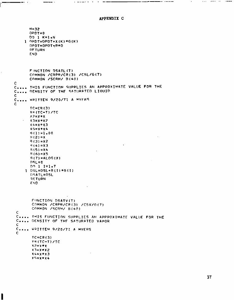
F ; lNCTI@N DSATL ( T I CCIMMON /CRPR/CR(3) / C S L / G ( 7 ) COMMON / S C R H / B ( 4 0 )
T H I S FUNCTION S I IPPL IES AN APPROXIMATE VALUE F O R THE OENSITY OF THF 54TIJRATED L I Q U I D
WRITTEN 9 / 2 0 / 7 1 A MYfR5
TC=CR (3) X = (TC-T) /TC.W,?=x*x x 3 = x * x 2 x 4 = x * x 3 x ' ? = x * x 4 Y ( 1 ) = l o 0 0 H(.Z)=X B (3)= X 2 q ( 4 ) = x 3 Y ( 5 )=x4 R ( 6 )=x5 rj (7)=ALOG ( X 1 DSL=O D q 1 I=1,7 DSL=DSL*E ( 11 *G ( 1 ) DqATL=DSL QETURN EWD
Fl lNCTION DSATV ( T I CnMMON /CRPR/CR(3) / C S V / B ( 7 ) COMMON /SCRH/ H ( 4 0 )
T H I S FllFJCTION SUPPLIES A N APPROXIMATE VALUE FOR THE DENSITY OF THF SATURATED VAPOR
WqITTEN 9 / 2 0 / 7 1 A MYERS
TC=CR(3) r = (TC-T) /lC x?=x*X y 3 = x * x 2 x 4 = x * x 3 x 5 = x * x 4
37
I

APPENDIX C.
H ( 1)= l o 0 0 B ( Z ) = x R (3)=xz R ( 4 ) =x3 cj (5)= x 4 q ( 6 )= X 5 R ( 7 ) =ALOG IX ) nsv=o DO 1 I = l r 7
1 n s v = o s v * B (I1 * G ( I 1 . DSV = E X P ( D S V ) OSA T V=DS V RETURN �\ID
FUNCTION F I N G l ( T i n ) COHMON/CEOS/G(41)COMMON /SCRH/ X ( 4 0 )
C C.... ROUTINE C C".. JQITTEN C
!?2=D*D 03=DZ*D 04=03*D DS=DQ*D 06=D5+D D7=D6+D 98=D7*D D9=DR*D 810=D99D
TO CALCULATE I N T E G R A L ( ( R / O - l / D * + Z ( D P / D T ) ) OD)
7 /18/71 A MYERS
38

APPENDIX C
F U N C T I O N F I N G 2 t T i D ) C O Y M O N / C E O S / G ( Q I ) COMMON /SCRH/ X ( 4 0 )
39

APPENDIX C
40

APPENDIX C
-FlNG2=0 D O 1 1 ~ 1 9 3 2
1 F ~ N G 2 = F I N G t + G ( I ) * X ( I ) AFTURN FUD
4 1
I... m . ,

APPENDIX C
X(22)=6eOOO*G2/T3 X(23 )=20oOO*G2/TS X(24)=6oOOO*G3/T3 X(25 )=12eOO*G3/T4 v (26 )=6oOOO*G4/T3 X(27)=2OeOOaG4/T5 Y(2P)=6eOOO*G5/T3 1 ( 2 9 ) = 1 2 o O O * G S / T 4 .Y(30)=6eOOO*G6/T3 X ( 3 1 ) = 1 2 e O O * G 6 / 1 4 X(32 )=20oOO*G6LT5 FING3=O !In 1 I z l . 3 2 '
1 F I N G 3 = F I N 6 3 + G (I)( I )* X QFTURN FiJD
FllNCTIOhl V I S C ( D D 9 T T ) ')TMENSIOY 7 ( 1 8 ) r X ( l l ) i?ATA( 2 = - h o 8 9 3 9 1 2 7 4 7 S E + 0 1 3 e 5 2 2 6 1 1 8 9 8 3 � + 0 0 9
C - 6 0 8 3 5 7 5 3 9 8 2 3 F - 0 2 9 1 0 5 8 3 2 7 1 7 3 1 5 E - 0 3 9 - 2 0 6 4 1 8 4 2 3 0 4 7 E - 0 6 9
C 3 e 6 0 9 3 3 0 9 1 3 8 E - 0 9 9 - 2 0 5 5 5 5 5 9 R 4 7 6 E - 1 2 9 8 e 5 6 3 5 0 4 1 6 4 1 E - 1 6 9
C - 1 e 0 7 1 7 5 9 9 4 0 6 E - 1 9 9 7 e 4 1 6 5 3 2 2 9 0 4 E + 0 1 9 - 1 e 5 8 3 4 4 0 0 4 7 5 � * 0 0 9
C 3 - 8 5 3 0 7 7 1 0 1 1 F - 0 3 P e 0 1 3 3 7 1 3 6 6 8 E - 0 4 9 - 8 0 9 2 0 3 1 2 3 8 4 6 E - 0 7 9
C 8 o 9 0 5 9 7 1 1 3 1 5 E - 1 0 9 - 5 0 3 7 7 9 3 7 2 6 b 4 E - 1 3 9 1 0 7 3 9 8 2 7 7 3 0 9 E - 1 6 9
C - 2 a 3 0 8 4 0 4 4 9 4 2 E - 2 0 ) ~ A T A ~ X ~ 2 ~ 3 0 8 3 5 1 4 3 6 2 E ~ 1 ~ ~ 9 e 3 6 3 6 2 0 7 1 7 1 E ~ 1 r 9 e 0 3 3 9 1 8 6 4 5 2 E + 0 ~ ~ 4 e 1 8 3 2 0 6 7 ~ 1 ~ 3 E ~ l r l e O R 9 7 6 2 7 8 9 3 E + 2 ~ ~ 1 e 2 9 1 3 8 5 6 3 7 6 E + 2 ~ 5 e ~ ~ ~ 2 0 4 9 9 ~ ~ E + ~ ~
J = 9 B K = 2 r,n T O 1 0 0 FVTRY THERM J = O S K = l
1 0 0 CONTINUE V ISC = 0 S T = TT $ D = DD 09 2 0 0 I = 1 * 9
V I S C = V I S C + T * * ( I - 3 ) * Z ( I + J ) 2 0 0 CnNTIlVl lE
GO TO ( 3 0 0 r 4 0 0 ) r K 3 0 0 CVNTINlrE
V I S C = V I S C + e 2 1 9 5 9 0 3 2 1 9 0 * D + e 0 6 3 8 7 3 7 0 6 9 9 0 * ( E X P ( 3 . 6 * D ) - l e 1 QETURN
4 0 0 CONTINUE IF (DeGToO.8 ) GO TO 5 0 1 DO 5 0 0 I = l r 7
V I S C = V I S C + X ( 1 ) * D**I 5 0 0 CONTIWJE
QETURN 5 0 1 V~SC=VISC~2e57R19909l~E+3+9e47R4808659E+3*D-lel622926973E+4*D~*2+
1 4 e 7 5 6 9 4 8 5 3 8 � + 3 * O * * 3 C IYPUT I)=GM/CC* T=DEG K C nt lTPUT E T A = M I L I GY/CM-SEC LAMRDA=MW/CM-K
RETURN END
42

APPENDIX C
43

-----
Sample Output
ENCRGY AN0 PDUER REQUIREMENTS FOR FAN-DRIVEN CRYOGENIC kIND-TUNNEL ISENTRQPIC C O M P R E S S I O N I N NITROGEN
TEST-SECTION NACH NUNBER,. 1 .20 FAN PRESSURE R A T I O = 1 .2000 FAN PRESSURE# DUTLtT * 5 .0000 A T M FAN PRESSURE, INLET 4.1667 ATN
E = FAN ENERGY P FAN P O U E R
~ 2 4 6 . 7 260.0 1252.6 13661.5 .1711E+08 259.9 124Y 0 13704.4 , 1 7 1 2 E t 0 8 1.0029 .9969 .9997 E 237.2 250.0 1277.9 13125.3 .1677E+08 2 4 9 9 1273.7 13176.9 r 1 6 7 8 E t 0 8 1.0033 a 9 9 6 1 .9993 227.7 240.0 1304.9 12588.2 .1643E+08 239.9 1300.0 12649.5 r 1 6 4 4 E t 0 8 1.0037 ,9952 ,9989 0 218.2 230.0 1333.7 12050.1 .1607E t o 8 229.9 1328.0 12122 .1 1 6 1 0 E t 0 8 1.0043 9 9 4 1 .9983 208.8 2 2 0 .o 1364.5 11510.7 .1571E+08 219.9 1357.9 11594.6 a 1 5 7 4 E t 0 8 1.0049 ,9928 e9976 199.3 210.0 1397.7 10969.9 1 5 33E*0@ 209.9 1389.8 11067.1 e 1 5 3 8 E t 0 8 1.0056 .9912 e9968 189.8 200.0 1433.5. 10427.5 . 1 4 9 5 E t 0 8 199.9 1424.2 10539.6 * 1 5 0 1 E + 0 8 1.0065 ,9894 .9958 180.3 190.0 1472.3 9883.0 1455EtO8 189.9 1461.2 10012.1 a 1 4 6 3 E t 0 8 1.0076 e 9 8 7 1 ,9946 170.8 1 8 0 .o 1514.7 9336.0 .1414E+08 179.9 1501.3 9484.6 1424E t o 8 1.0089 .9843 e 9 9 3 1 161.3 170.0 1561 .1 8786.1 - 1 3 7 2 E t 0 8 169.9 1544.9 8957.0 1 3 8 4 E t 0 8 1.0105 - 9 8 0 9 ,9912 151.8 160.0 1612.5 8 2 3 2 . 3 . 1 3 2 7 E t 0 8 159.9 1592.5 8429.5 r 1 3 4 2 E t 0 8 1.0125 ~ 9 7 6 6 ,9889 142.3 150.0 1665.7 7673.7 , 1 2 8 l E t 0 8 149.9 1644.8 7901.9 4 1 3 0 0 E t 0 8 1 .0151 - 9 7 1 1 .9858 132.8 140.0 1734.2 7108.6 - 1 2 3 3 E t 0 8 139.9 1702.7 7374.2 r 1 2 5 6 E t 0 8 1.0185 e9640 e9818 123.3 1 3 0 -0 1807 .8 6534.8 .1181E+O8 129.9 1767.0 6846.6 e 1 2 1 0 E t 0 8 1 .0231 .9545 ,9765 113.8 120.0 1893.5 5348.5 . 1 1 2 6 E t 0 8 119.8 1839.3 6318.9 . 1 1 6 2 E t 0 8 1.0294 ,9414 e 9 6 9 1 109.0 115.0 1942 2 5648.9 .1097E+08 114 .8 1879 .0 6055 .1 1138 E t o 8 1.0336 - 9 3 2 9 - 9 6 4 3 104.3 110.0 1995.8 5343.4 1066EtOe 109.8 1921.3 5791.2 1 1 1 3 E t 0 8 1.0388 .9227 .9584
99.5 105 - 0 2055.5 5030.5 . 1 0 3 4 � + 0 8 104.8 1966.6 5527.4 e 1 0 8 7 E t 0 8 1.0452 e 9 1 0 1 ,9512
REALl IDEAL VALUES----TT, I N
K TT, OUT
K M O O T
K G M / 5-fi2 ElNASS JlKGN
Q / A R E A J I S-H2
TTIOUT K
N O O T KGN/S-H2
� / M A S S J/KGPI
P l A R E A J/S-NZ
NDOT P/AREA
294.2 310.0 1145.5 16332.7 .1871E+08 309.9 1143.8 16341.6 r 1 8 6 9 E t 0 8 1.0015 ,9995 1.0010 284.7 275.2
3 0 0 a0 290.0
1164.7 1184.9
15799.5 15265.9
.1840E+OR , 1 8 0 9 E t 0 6
299.9 289.9
1162.7 1182.6
15814 .1 15286.7
1 8 3 9 E t 0 8 .1808E t o 8
1.0017 e 9 9 9 1 1.0008 1.0020 e9986 1.0006 2
265.7 280.0 1206.2 14731.7 . 1 7 7 7 E t 0 8 279.9 1203.5 14759.2 , 1 7 7 6 E t 0 8 1.0022 e 9 9 8 1 256.2 270.0 1228.7 14197.0 .1744E+08 269.9 1225.6 14231.8 r 1 7 4 4 E t 0 8 1.0025 ,9976 1.0001
1 0 0 0 4 3
SATURATION CCINOITIONS PEACHED A T THROAT MACH NUMBER
. -
Output variables: TT,IN, stagnation temperature at fan inlet, K; TT,OUT, stagnation temperature at fan outlet, K; MDOT, mass-flow rate per unit throat area, kgm/sec-m2. E/MASS, fan energy per unit mass of flow, J/kgm; P/AREA, fan power per unit throat area, J/sec-m2 .
I -
REFERENCES
1 . Kilgore, Robert Ashworth: The Cryogenic Wind Tunnel f o r High Reynolds Number Test ing. Ph. D. Thes is , Southampton Univ. (England), Feb. 1974.
2. Kilgore , Robert A. ; Goodyer, Michael J . ; Adcock, J e r r y B.; and Davenport, Edwin E.: The Cryogenic Wind-Tunnel Concept f o r High Reynolds Number Testing. NASA TN D-7762, 1974.
3 . Kilgore., Robert A. ; Adcock, J e r r y B.; and Ray, Edward J.: Simulat ion of F l i g h t Test Condi t ions i n t h e Langley P i l o t Transonic C!'ryogenic Tunnel. NASA TN D-7811, 1974.
4 . Smelt , R.: Power Economy i n High-speed Wind Tunnels by Choice of Working .Fluid and Temperature. Rep. No. Aero. 2081, B r i t i s h R.A.E . , Aug. 1945.
5. Adcock, J e r r y B.: Real-Gas Effects Associated With One-Dimensional T r a n son ic Flow of Cryogenic Nitrogen. NASA TN D-8274, 1976.
6 . McKinney, Linwood W.: and Howell, Robert R . : The C h a r a c t e r i s t i c s of t h e ' Planned Nat iona l Transonic F a c i l i t y . Proceedings 9 t h Aerodynamics Testing
Conference, June 1976, pp. 176-184.
7 . Jacobsen, R. T . ; S tewar t , R . 'B.; McCarty, R . D . ; and Hanley, H. J. M.: Thermophysical P r o p e r t i e s o f Nitrogen From t h e Fusion Line t o 3500 R (1944 . K ) f o r Pressures t o 150 000 p s i a '(IO 342 x IO5 N/m2). NBS Tech. Note 648, U.S. Dep. Com., D e c . 1973.
8. Jacobsen, Richard T.: The Thermodynamic P r o p e r t i e s of Nitrogen From 65 t o 2000 K With Pressures t o 10,000 Atmospheres. Ph. D . Thes i s , Washington S t a t e Univ., 1972. (Avai lab le as NASA CR-128526.)
9 . Marks,Lionel S., ed.: Mechanical Engineers ' Handbook. F i f t h ed. M c G r a w - H i l l Book Co., I n c . , 1951, p. 1881.
45
'i P.
I, amb
.5 ,F
-. 4
. 3
1 . 2 !
.1 IC
0 - .
100 150 200 250 300
Figure 1.- Varia t ion of tunne l d r i v e power w i t h tunnel opera t ing temperature. MTS = 1.0.

T hroat Tunnel energy losses 2 9 Tt, 2 9 and M T H ) \ occur in shaded portion
/ - T e s t section
Cooler mass addit ion)
Downstream conditions Fan Upst ream conditions t Isentropic compression) (Pt, 1' Tt, 1)
Figure 2.- Analytical model of tunnel.

PROGRAM INPUTS
Test-section conditions: Fan Dressure ratio:
I
I Set MTH
ys> 1.0 MTH 1.0
MTS< MTH MTS-r Throat conditions
(Real gas) PI T, P , v, m r -"--------"------
Check for sat uration
Initial test-section temperature set I (Tt. 2)r = 310 K
. _1-
1 'hroat conditions I
(Real gas) r Term inate solutions0
48
L
'r
I
PROGRAM OUTPUTS Fan inlet conditions: Pt, 1' Tt, 1 Real-gas values: 'Tt,2)RI E,., mr9 Pr
Ideal-gas values: (Tt,2)i., Ei, mi, Pi
Ratios: Er/Ei, mrlmi, PrlPi

1.03
1.02
1.01
e ,"
.97
100 1% 200
Inlet temperature, T, ,, K 250
1, 1
Figure 4.- Relative value of downstream stagnation temperature as function of inlet stagnation temperature. pt,2 = 8.8 atm and r = 1.20. '

VI0 1.00
.98
.96
.94
.92
.90
.88
.86
.84
Figure 5.- Energy
100
for isentropic
150 200 250
ideal-gas values).
r,,2 ' (a) pt,2 = 1.0 atm.
compressions of nitrogen (relative to

1.00
.98
.96
94
.92
.88
.86
100 150
Tt,2 ' K
200
(b) ~ t , 2= 3.0 atm.
Figure 5.- Continued.
250

1.00
.98
;96
.94
.92
-E. .90
a 88
100 150 200 250
CCT - P t 2 = 5.0 atm.
- Continued.Figure 5
I

E
'i
.88
.86
.84
100 1% 200
(d) Pt
Figure 5
2 = 8.8 atm.
- Concluded.VI W

4000
h,
J Mole-K
3000
1
L
I I I I I I 80 100 120 140 160 '
T , K
Figure 6.- Variat ion of enthalpy with temperature along i sen t ropes .

e 98
-Ei
0 1 2 3 4 5 6 7 8 9 10
Figure 7.- Variation of i s en t rop ic compression energy f o r nitrogen with s tagnat ion pressure VI 4 ( r e l a t i v e t o ideal-gas values). r = 1.025. VI

07
06
05
m r r
'i
100 150 200 250
Tt,2 (a> pt,2 = 1 .0 atm.
Figure 8.- Relative mass-flow for various stagnation temperaturesand pressures of tunnel throat.

1.07
mi
100 150 200 250
(b) pt,2 = 3.0 atm.
Figure 8.- Continued.

mr-mi
Tt,2 ,K ( c ) pt,2 = 5.0 atm.
Figure 8.- Continued.

100 150 250
Tt,2 ( d ) pt,2 = 8 .8 atm.
Figure 8 . - Concluded.

m 0
LOO
.99
98
.97
96
e 95
.94
.93
.92
150 200 250
Tt,2 IK
(a> P ~ , , , ~1.0 atm.I =
Figure 9.- Relative isentropic power values for various stagnation temperatures and pressures.

1. 00
.99
98 r
. 9 7
'r . 9 6
. 9 5
. 9 4
e 9 3
9 2
100 150 200
Tt,2 ' (b) pt,2 = 3.0 atm.
Figure 9.- Continued.
250

1 00
99
98
. 9 1
P-r .96 P.
I
. 95
100 150 200 250
( c ) pt,2 5.0 atm.
Figure 9.- Continued.

1.00
.'99
. 9 8
. 9 7
. 9 6
. 9 5
. 94
. 9 3
. 9 2
. 9 1
150 200 250
*t,2
(d ) p t , 2 = 8.8 atm.
9.- Concluded.
LOO
.98
.96
.94
.92
.86
.84
.82
.78
P, f m
Figure 10.- Compressibility factor for nitrogen (ref. 7).
64

LOO
.98
.96
e 94
.92
.90
.88
.86
.84
100 150 200 250 300
Tt,2
Figure 1 1 . - Estimates of energy for isentropic compressions of nitrogen compared with exact values. pt,2 = 8.8 atm; r = 1.20.

100 150 ' 250
Figure 12.- Approximation f o r real-gas mass-flow rates of nitrogen ( i s en t rop ic flow).
.

F
.99
.98
.97
p,
.94
.93
.92
.91
r MTS
1.200 L20
100 150 200 250 Tt,2 : K
Figure 13.- Approximation f o r power required f o r i s en t rop ic compressions of ni t rogen.

e-L1Static conditionsI (Initial-Ideal) I
0 16
Terminate Check for solutions 3 saturation atI
Figure 14.- Flow chart of real-gas
For: T p Returns: c I0-Call MVCAL _ .
For: htJ2, h, C
Returns: M ,
1 Check Mach Mass-flow rate conve rgence to memory
I No
I ’ Cal l TCHANG1 Finds AT/AM at St,*
c a l c u l a t i o n s of tunne l t h r o a t condi t ions .
68
... .
Pt,2' Tt,2' St,2' ht,2' h
+In le t temperature guess
1 .).
Call ProD I
IFor: (Tt, 1
x l.bOl), P t. 1
(Re tu rn - ( st. 1lU
Check entropy convergence
ISt, 1 - St, 1 x 10
..7 ~~ 1
Figure 15.- Flow c h a r t for r ea l -gas c a l c u l a t i o n s of f an parameters .
NASA-Langley, 1977 L-1 1 184 69

NATIONAL AERONAUTICS AND SPACE ADMINISTRATION WASHINGTON, D.C. 20546
OFF1C I AL BUS IN ESS PENALTY FOR PRIVATE USE $300 SPECIAL FOURTH-CLASS RATE
BOOK
210 0 0 1 C 1 U D 770317 SO0903DS DEFT OF Tidl2 AI!.? FOECi3 k F WSAPONS L A B C R A T O i i Y AI’TN: TECHlYXCBL LIBRARY (SUI,) K I R T L A N D AI’a NEI 87117
P O S T A G E A N D F E E S P A I D N A T I O N A L AERONAUTICS A N D
S P A C E ADMINISTRATION 451 [*,JUSMAIL
!
If Undeliverable (Section 158BSTIR : Postal Mnnual) Do Not Return
“The aeronautical and space activities of the United States shall be conducted so as t o contribute . . . t o the expansion of human knowledge of phenomena in the atmosphere and space. The Administration shall provide for the widest practicable and appropriate dissemination of information concerning its activities and the results thereof.”
-NATIONALAERONAUTICSAND SPACE ACT OF 1958
NASA SCIENTIFIC AND TECHNICAL PUBLICATIONS TECHNICAL REPORTS: Scientific and ,
technical information considered important, complete, and a lasting contribution to existing knowledge.
TECHNICAL NOTES: Information less broad in scope but nevertheless of importance as a contribution to existing knowledge.
TECHNICAL MEMORANDUMS: Information receiving limited distribution because of preliminary data, security classification, or other reasons. Also includes conference proceedings with either limited or unlimited distribution.
CONTRACTOR REPORTS: Scientific and technical information generated under a NASA contract or grant and considered an important contribution to existing knowledge.
TECHNICAL TRANSLATIONS: Information published in a foreign language considered to merit NASA distribution in English.
PUBLICAT1oNS: Information derived from or of value to NASA activities. Publications include final reports of major projects, monographs, data compilations, handbooks, sourcebooks, and special bibliographies.
TECHNOLOGY UTILIZATION PUBLICATIONS: Information on technology used by NASA that may be of particular interest in commercial and other-non-aerospace applications. Publications include Tech Briefs, Technology Utilization Reports and Technology Surveys.
Details on the availability of these publications may be obtained from:
SCIENTIFIC AND TECHNICAL INFORMATION OFFICE
N A T I O N A L A E R O N A U T I C S A N D SPACE A D M I N I S T R A T I O N Washington, D.C. 20546


![[hal-00878559, v1] Stochastic isentropic Euler equations](https://img.pdfslide.net/doc/110x75/61870549a8b9ae791f473b55/hal-00878559-v1-stochastic-isentropic-euler-equations.jpg)