Embed Size (px)
Citation preview
Power Capacitors B25667B3247A375 Power Factor Correction MKK400-D-12.5-01
Edition 2. FK PFC RD / VA 20.10.05
Page 1 of 3
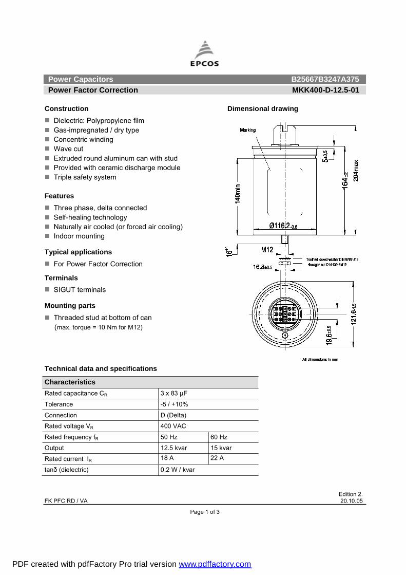
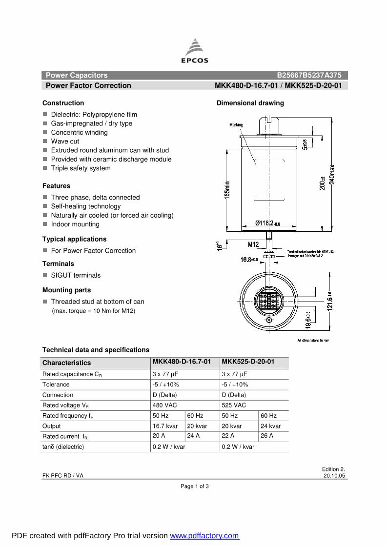
Construction Dimensional drawing
Dielectric: Polypropylene film Gas-impregnated / dry type Concentric winding Wave cut Extruded round aluminum can with stud Provided with ceramic discharge module Triple safety system
FeaturesThree phase, delta connected Self-healing technology Naturally air cooled (or forced air cooling) Indoor mounting
Typical applications For Power Factor Correction
TerminalsSIGUT terminals
Mounting parts Threaded stud at bottom of can
(max. torque = 10 Nm for M12)
Technical data and specifications
Characteristics Rated capacitance CR 3 x 83 µF
Tolerance -5 / +10%
Connection D (Delta)
Rated voltage VR 400 VAC
Rated frequency fR 50 Hz 60 Hz
Output 12.5 kvar 15 kvar
Rated current IR 18 A 22 A
tan (dielectric) 0.2 W / kvar
PDF created with pdfFactory Pro trial version www.pdffactory.com
Power Capacitors B25667B3247A375 Power Factor Correction MKK400-D-12.5-01
Edition 2. FK PFC RD / VA 20.10.05
Page 2 of 3
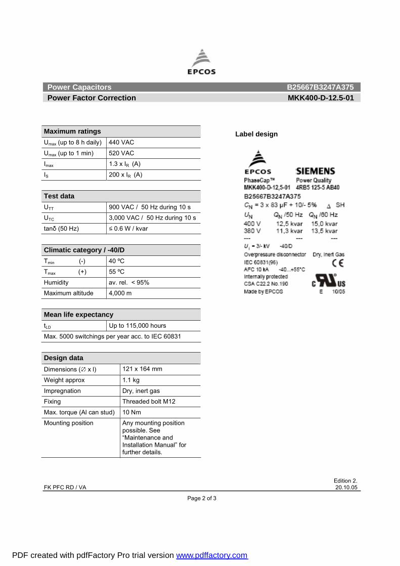
Maximum ratings Umax (up to 8 h daily) 440 VAC
Umax (up to 1 min) 520 VAC
Imax 1.3 x IR (A)
IS 200 x IR (A)
Test data UTT 900 VAC / 50 Hz during 10 s
UTC 3,000 VAC / 50 Hz during 10 s
tan (50 Hz) 0.6 W / kvar
Climatic category / -40/D Tmin (-) 40 ºC
Tmax (+) 55 ºC
Humidity av. rel. < 95%
Maximum altitude 4,000 m Mean life expectancy tLD Up to 115,000 hours
Max. 5000 switchings per year acc. to IEC 60831
Design data Dimensions ( x l) 121 x 164 mm
Weight approx 1.1 kg
Impregnation Dry, inert gas
Fixing Threaded bolt M12
Max. torque (Al can stud) 10 Nm
Mounting position Any mounting position possible. See �Maintenance and Installation Manual� for further details.
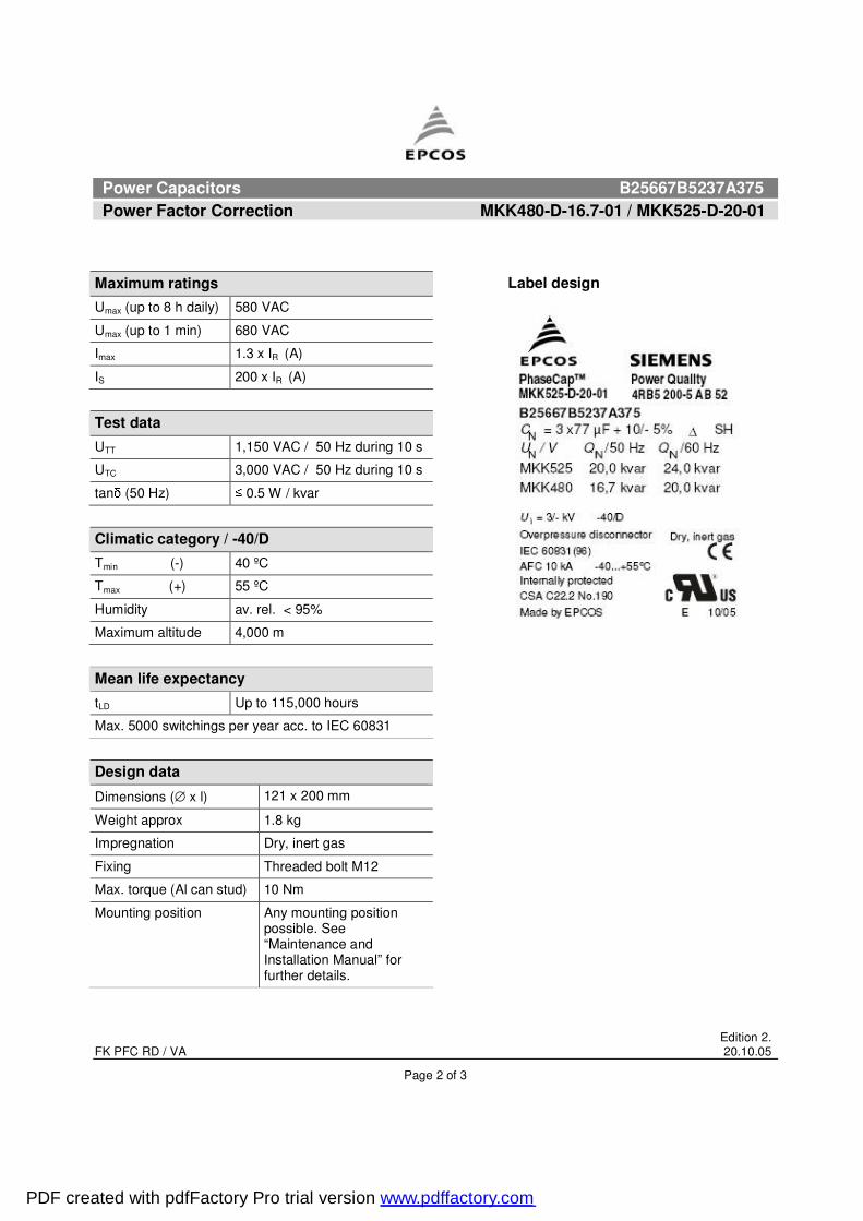
Label design
PDF created with pdfFactory Pro trial version www.pdffactory.com

Power Capacitors B25667B3247A375 Power Factor Correction MKK400-D-12.5-01
Edition 2. FK PFC RD / VA 20.10.05
Page 3 of 3
Please read information about PFC capacitors and cautions as well as installation and maintenance instructions (Power Factor Correction Product Profile, actual version, and Installation and Maintenance Instructions for PFC-capacitors, available in the Internet) to ensure optimum performance and prevent products from failing, and in worst case, bursting and fire. Information given in the PFC-product profile and values given in the data sheet reflect typical specifications. You are kindly requested to approve our product specifications or request our approval for your specification before ordering.
EPCOS AG 2005. All Rights reserved. Reproduction, publication and dissemination of this data sheet, enclosures hereto and the information contained therein without EPCOS' prior express consent is prohibited. The information contained in this data sheet describes the type of component and shall not be considered as guaranteed characteristics. Purchase orders are subject to the General Conditions for the Supply of Products and Services of the Electrical and Electronics Industry recommended by the ZVEI (German Electrical and Electronic Manufacturers' Association), unless otherwise agreed.
TerminalsDegree of protection Isolated terminals, IP20
Max. torque 1.2 Nm
Terminal cross section 16 mm2 (5 AWG)
Maximum terminal current 50 A
Creepage distance 12.7 mm
Clearance 9.6 mm
Safety Mechanical safety Overpressure disconnector
Max. short circuit current (AFC: 10 kA)
Discharge resistor time 1 min (75 V)
Reference Standards IEC 60831-1/2, UL 810-5th edition
Certification: cUL file E238746
PDF created with pdfFactory Pro trial version www.pdffactory.com

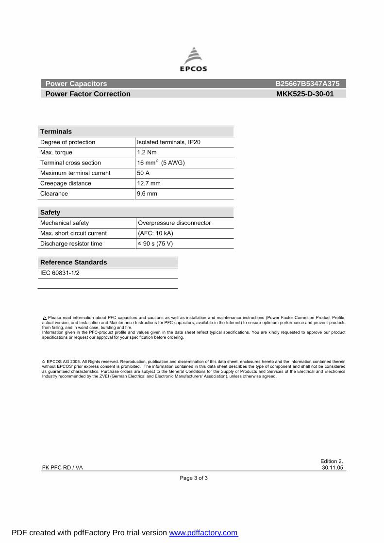
Power Capacitors B25667B5347A375 Power Factor Correction MKK525-D-30-01
Edition 2. FK PFC RD / VA 30.11.05
Page 1 of 3
Construction Dimensional drawing
Dielectric: Polypropylene film Gas-impregnated / dry type Concentric winding Wave cut Extruded round aluminum can with stud Provided with ceramic discharge module Triple safety system
FeaturesThree phase, delta connected Self-healing technology Naturally air cooled (or forced air cooling) Indoor mounting
Typical applications For Power Factor Correction
TerminalsSIGUT terminals
Mounting parts Threaded stud at bottom of can
(max. torque = 10 Nm for M12)
Technical data and specifications
Characteristics Rated capacitance CR 3 x 115 µF
Tolerance -5 / +10%
Connection D (Delta)
Rated voltage VR 525 VAC
Rated frequency fR 50 Hz 60 Hz
Output 30 kvar --
Rated current IR 33 A --
tan (dielectric) 0.2 W / kvar
PDF created with pdfFactory Pro trial version www.pdffactory.com
Power Capacitors B25667B5347A375 Power Factor Correction MKK525-D-30-01
Edition 2. FK PFC RD / VA 30.11.05
Page 2 of 3
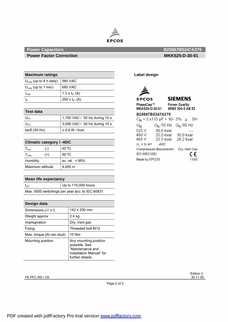
Maximum ratings Umax (up to 8 h daily) 580 VAC
Umax (up to 1 min) 680 VAC
Imax 1.3 x IR (A)
IS 200 x IR (A)
Test data UTT 1,150 VAC / 50 Hz during 10 s
UTC 3,000 VAC / 50 Hz during 10 s
tan (50 Hz) 0.6 W / kvar
Climatic category / -40/C Tmin (-) 40 ºC
Tmax (+) 50 ºC
Humidity av. rel. < 95%
Maximum altitude 4,000 m Mean life expectancy tLD Up to 115,000 hours
Max. 5000 switchings per year acc. to IEC 60831 Design data Dimensions ( x l) 142 x 200 mm
Weight approx 2.4 kg
Impregnation Dry, inert gas
Fixing Threaded bolt M12
Max. torque (Al can stud) 10 Nm
Mounting position Any mounting position possible. See �Maintenance and Installation Manual� for further details.
Label design
PDF created with pdfFactory Pro trial version www.pdffactory.com
Power Capacitors B25667B5347A375 Power Factor Correction MKK525-D-30-01
Edition 2. FK PFC RD / VA 30.11.05
Page 3 of 3
Please read information about PFC capacitors and cautions as well as installation and maintenance instructions (Power Factor Correction Product Profile, actual version, and Installation and Maintenance Instructions for PFC-capacitors, available in the Internet) to ensure optimum performance and prevent products from failing, and in worst case, bursting and fire. Information given in the PFC-product profile and values given in the data sheet reflect typical specifications. You are kindly requested to approve our product specifications or request our approval for your specification before ordering.
EPCOS AG 2005. All Rights reserved. Reproduction, publication and dissemination of this data sheet, enclosures hereto and the information contained therein without EPCOS' prior express consent is prohibited. The information contained in this data sheet describes the type of component and shall not be considered as guaranteed characteristics. Purchase orders are subject to the General Conditions for the Supply of Products and Services of the Electrical and Electronics Industry recommended by the ZVEI (German Electrical and Electronic Manufacturers' Association), unless otherwise agreed.
TerminalsDegree of protection Isolated terminals, IP20
Max. torque 1.2 Nm
Terminal cross section 16 mm2 (5 AWG)
Maximum terminal current 50 A
Creepage distance 12.7 mm
Clearance 9.6 mm
Safety Mechanical safety Overpressure disconnector
Max. short circuit current (AFC: 10 kA)
Discharge resistor time 90 s (75 V)
Reference Standards IEC 60831-1/2
PDF created with pdfFactory Pro trial version www.pdffactory.com

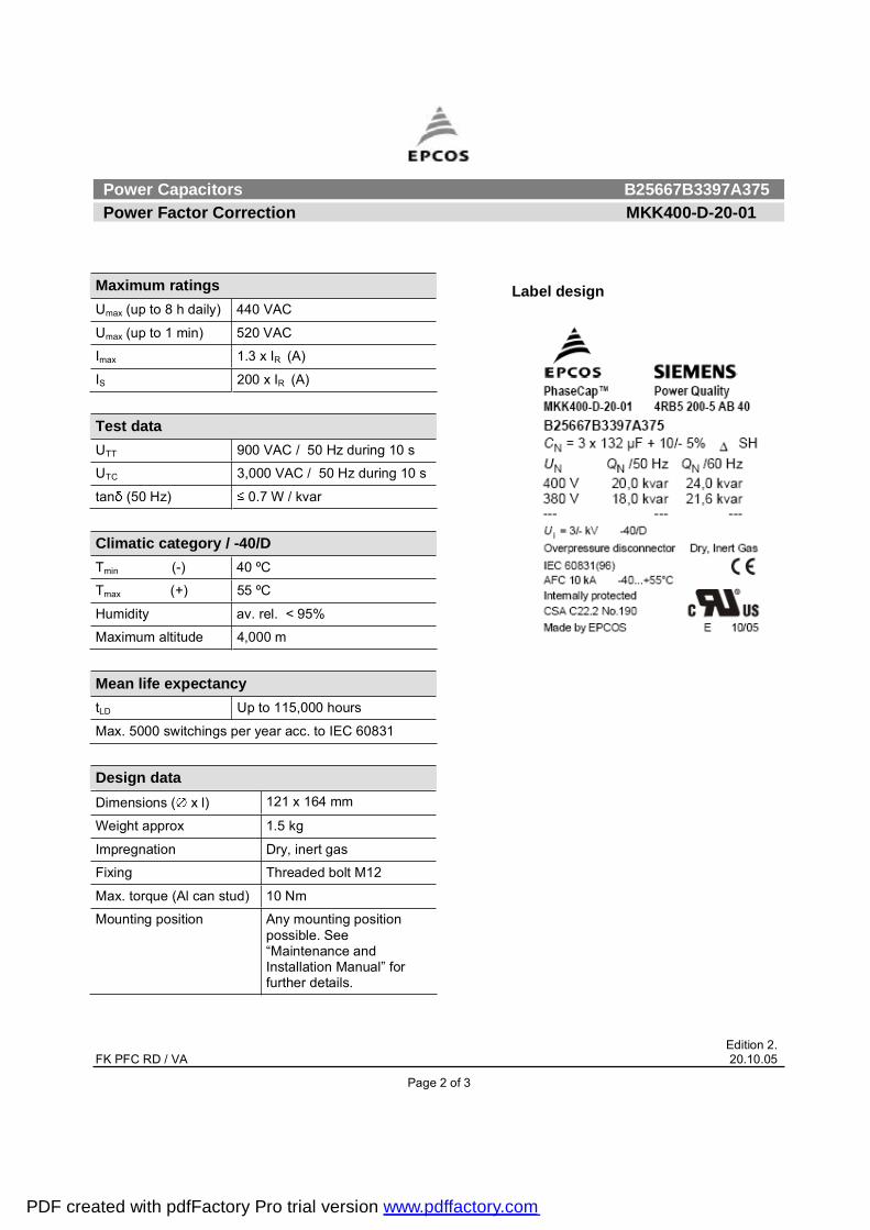
Power Capacitors B25667B3397A375 Power Factor Correction MKK400-D-20-01
Edition 2. FK PFC RD / VA 20.10.05
Page 1 of 3
Construction Dimensional drawing
Dielectric: Polypropylene film Gas-impregnated / dry type Concentric winding Wave cut Extruded round aluminum can with stud Provided with ceramic discharge module Triple safety system
FeaturesThree phase, delta connected Self-healing technology Naturally air cooled (or forced air cooling) Indoor mounting
Typical applications For Power Factor Correction
TerminalsSIGUT terminals
Mounting parts Threaded stud at bottom of can
(max. torque = 10 Nm for M12)
Technical data and specifications
Characteristics Rated capacitance CR 3 x 132 µF
Tolerance -5 / +10%
Connection D (Delta)
Rated voltage VR 400 VAC
Rated frequency fR 50 Hz 60 Hz
Output 20 kvar 24 kvar
Rated current IR 30 A 36 A
tan (dielectric) 0.2 W / kvar
PDF created with pdfFactory Pro trial version www.pdffactory.com
Power Capacitors B25667B3397A375 Power Factor Correction MKK400-D-20-01
Edition 2. FK PFC RD / VA 20.10.05
Page 2 of 3
Maximum ratings Umax (up to 8 h daily) 440 VAC
Umax (up to 1 min) 520 VAC
Imax 1.3 x IR (A)
IS 200 x IR (A)
Test data UTT 900 VAC / 50 Hz during 10 s
UTC 3,000 VAC / 50 Hz during 10 s
tan (50 Hz) 0.7 W / kvar
Climatic category / -40/D Tmin (-) 40 ºC
Tmax (+) 55 ºC
Humidity av. rel. < 95%
Maximum altitude 4,000 m Mean life expectancy tLD Up to 115,000 hours
Max. 5000 switchings per year acc. to IEC 60831
Design data Dimensions ( x l) 121 x 164 mm
Weight approx 1.5 kg
Impregnation Dry, inert gas
Fixing Threaded bolt M12
Max. torque (Al can stud) 10 Nm
Mounting position Any mounting position possible. See �Maintenance and Installation Manual� for further details.
Label design
PDF created with pdfFactory Pro trial version www.pdffactory.com

Power Capacitors B25667B3397A375 Power Factor Correction MKK400-D-20-01
Edition 2. FK PFC RD / VA 20.10.05
Page 3 of 3
Please read information about PFC capacitors and cautions as well as installation and maintenance instructions (Power Factor Correction Product Profile, actual version, and Installation and Maintenance Instructions for PFC-capacitors, available in the Internet) to ensure optimum performance and prevent products from failing, and in worst case, bursting and fire. Information given in the PFC-product profile and values given in the data sheet reflect typical specifications. You are kindly requested to approve our product specifications or request our approval for your specification before ordering.
EPCOS AG 2005. All Rights reserved. Reproduction, publication and dissemination of this data sheet, enclosures hereto and the information contained therein without EPCOS' prior express consent is prohibited. The information contained in this data sheet describes the type of component and shall not be considered as guaranteed characteristics. Purchase orders are subject to the General Conditions for the Supply of Products and Services of the Electrical and Electronics Industry recommended by the ZVEI (German Electrical and Electronic Manufacturers' Association), unless otherwise agreed.
TerminalsDegree of protection Isolated terminals, IP20
Max. torque 1.2 Nm
Terminal cross section 16 mm2 (5 AWG)
Maximum terminal current 50 A
Creepage distance 12.7 mm
Clearance 9.6 mm
Safety Mechanical safety Overpressure disconnector
Max. short circuit current (AFC: 10 kA)
Discharge resistor time 1 min (75 V)
Reference Standards IEC 60831-1/2, UL 810-5th edition
Certification: cUL file E238746
PDF created with pdfFactory Pro trial version www.pdffactory.com
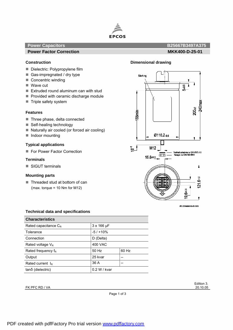
Power Capacitors B25667B3497A375 Power Factor Correction MKK400-D-25-01
Edition 3. FK PFC RD / VA 20.10.05
Page 1 of 3
Construction Dimensional drawing
Dielectric: Polypropylene film Gas-impregnated / dry type Concentric winding Wave cut Extruded round aluminum can with stud Provided with ceramic discharge module Triple safety system
FeaturesThree phase, delta connected Self-healing technology Naturally air cooled (or forced air cooling) Indoor mounting
Typical applications For Power Factor Correction
TerminalsSIGUT terminals
Mounting parts Threaded stud at bottom of can
(max. torque = 10 Nm for M12)
Technical data and specifications
Characteristics Rated capacitance CR 3 x 166 µF
Tolerance -5 / +10%
Connection D (Delta)
Rated voltage VR 400 VAC
Rated frequency fR 50 Hz 60 Hz
Output 25 kvar --
Rated current IR 36 A --
tan (dielectric) 0.2 W / kvar
PDF created with pdfFactory Pro trial version www.pdffactory.com
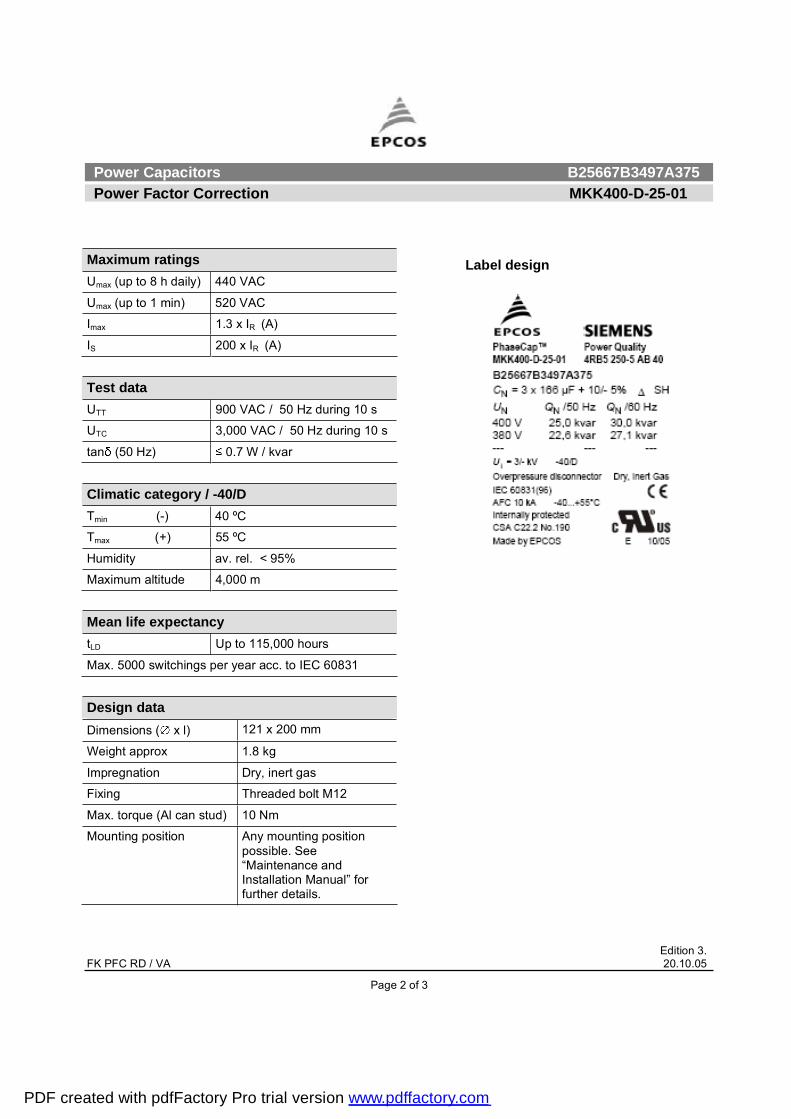
Power Capacitors B25667B3497A375 Power Factor Correction MKK400-D-25-01
Edition 3. FK PFC RD / VA 20.10.05
Page 2 of 3
Maximum ratings Umax (up to 8 h daily) 440 VAC
Umax (up to 1 min) 520 VAC
Imax 1.3 x IR (A)
IS 200 x IR (A)
Test data UTT 900 VAC / 50 Hz during 10 s
UTC 3,000 VAC / 50 Hz during 10 s
tan (50 Hz) 0.7 W / kvar
Climatic category / -40/D Tmin (-) 40 ºC
Tmax (+) 55 ºC
Humidity av. rel. < 95%
Maximum altitude 4,000 m Mean life expectancy tLD Up to 115,000 hours
Max. 5000 switchings per year acc. to IEC 60831
Design data Dimensions ( x l) 121 x 200 mm
Weight approx 1.8 kg
Impregnation Dry, inert gas
Fixing Threaded bolt M12
Max. torque (Al can stud) 10 Nm
Mounting position Any mounting position possible. See �Maintenance and Installation Manual� for further details.
Label design
PDF created with pdfFactory Pro trial version www.pdffactory.com

Power Capacitors B25667B3497A375 Power Factor Correction MKK400-D-25-01
Edition 3. FK PFC RD / VA 20.10.05
Page 3 of 3
Please read information about PFC capacitors and cautions as well as installation and maintenance instructions (Power Factor Correction Product Profile, actual version, and Installation and Maintenance Instructions for PFC-capacitors, available in the Internet) to ensure optimum performance and prevent products from failing, and in worst case, bursting and fire. Information given in the PFC-product profile and values given in the data sheet reflect typical specifications. You are kindly requested to approve our product specifications or request our approval for your specification before ordering.
EPCOS AG 2005. All Rights reserved. Reproduction, publication and dissemination of this data sheet, enclosures hereto and the information contained therein without EPCOS' prior express consent is prohibited. The information contained in this data sheet describes the type of component and shall not be considered as guaranteed characteristics. Purchase orders are subject to the General Conditions for the Supply of Products and Services of the Electrical and Electronics Industry recommended by the ZVEI (German Electrical and Electronic Manufacturers' Association), unless otherwise agreed.
TerminalsDegree of protection Isolated terminals, IP20
Max. torque 1.2 Nm
Terminal cross section 16 mm2 (5 AWG)
Maximum terminal current 50 A
Creepage distance 12.7 mm
Clearance 9.6 mm
Safety Mechanical safety Overpressure disconnector
Max. short circuit current (AFC: 10 kA)
Discharge resistor time 1 min (75 V)
Reference Standards IEC 60831-1/2, UL 810-5th edition
Certification: cUL file E238746
PDF created with pdfFactory Pro trial version www.pdffactory.com
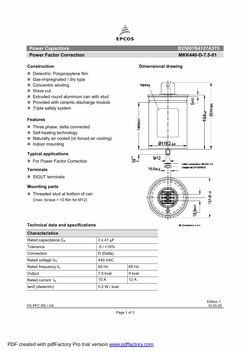
Power Capacitors B25667B4127A375Power Factor Correction MKK440-D-7.5-01
Edition 1. FK PFC RD / VA 10.03.05
Construction Dimensional drawingDielectric: Polypropylene film Gas-impregnated / dry type Concentric winding Wave cut Extruded round aluminum can with stud Provided with ceramic discharge module Triple safety system
FeaturesThree phase, delta connectedSelf-healing technology Naturally air cooled (or forced air cooling)Indoor mounting
Typical applicationsFor Power Factor Correction
TerminalsSIGUT terminals
Mounting partsThreaded stud at bottom of can
(max. torque = 10 Nm for M12)
Technical data and specifications
CharacteristicsRated capacitance CR 3 x 41 µF
Tolerance -5 / +10%
Connection D (Delta)
Rated voltage VR 440 VAC
Rated frequency fR 50 Hz 60 Hz
Output 7.5 kvar 9 kvar
Rated current IR 10 A 12 A
tan (dielectric) 0.2 W / kvar
Page 1 of 3
PDF created with pdfFactory Pro trial version www.pdffactory.com
Power Capacitors B25667B4127A375Power Factor Correction MKK440-D-7.5-01
Edition 1.
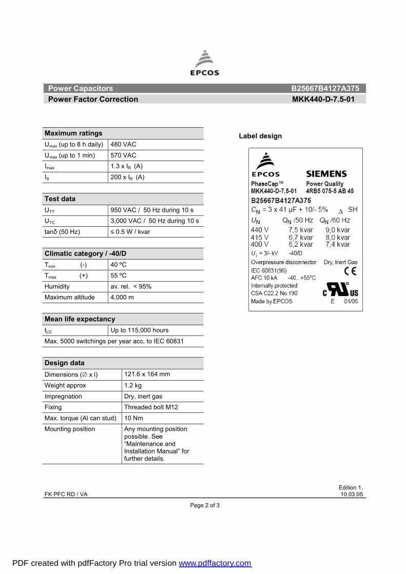
Label design Maximum ratings Umax (up to 8 h daily) 480 VAC
Umax (up to 1 min) 570 VAC
Imax 1.3 x IR (A)
IS 200 x IR (A)
Test data UTT 950 VAC / 50 Hz during 10 s
UTC 3,000 VAC / 50 Hz during 10 s
tan (50 Hz) 0.5 W / kvar
Climatic category / -40/DTmin (-) 40 ºC
Tmax (+) 55 ºC
Humidity av. rel. < 95%
Maximum altitude 4,000 m
Mean life expectancytLD Up to 115,000 hours
Max. 5000 switchings per year acc. to IEC 60831
Design data Dimensions ( x l) 121.6 x 164 mm
Weight approx 1.2 kg
Impregnation Dry, inert gas
Fixing Threaded bolt M12
Max. torque (Al can stud) 10 Nm
Mounting position Any mounting position possible. See �Maintenance and Installation Manual� for further details.
FK PFC RD / VA 10.03.05
Page 2 of 3
PDF created with pdfFactory Pro trial version www.pdffactory.com

Power Capacitors B25667B4127A375Power Factor Correction MKK440-D-7.5-01
Edition 1.
TerminalsDegree of protection Isolated terminals, IP20
Max. torque 1.2 Nm
Terminal cross section 16 mm2 (5 AWG)
Maximum terminal current 50 A
Creepage distance 12.7 mm
Clearance 9.6 mm
SafetyMechanical safety Overpressure disconnector
Max. short circuit current (AFC: 10 kA)
Discharge resistor time 1 min (75 V)
Reference standards IEC 60831-1/2, UL 810-5th edition
Certification: cUL file E238746
Please read information about PFC capacitors and cautions as well as installation and maintenance instructions (Power Factor Correction Product Profile,actual version, and Installation and Maintenance Instructions for PFC-capacitors, available in the Internet) to ensure optimum performance and prevent productsfrom failing, and in worst case, bursting and fire.Information given in the PFC-product profile and values given in the data sheet reflect typical specifications. You are kindly requested to approve our productspecifications or request our approval for your specification before ordering.
EPCOS AG 2005. All Rights reserved. Reproduction, publication and dissemination of this data sheet, enclosures hereto and the information contained thereinwithout EPCOS' prior express consent is prohibited. The information contained in this data sheet describes the type of component and shall not be consideredas guaranteed characteristics. Purchase orders are subject to the General Conditions for the Supply of Products and Services of the Electrical and ElectronicsIndustry recommended by the ZVEI (German Electrical and Electronic Manufacturers' Association), unless otherwise agreed.
FK PFC RD / VA 10.03.05
Page 3 of 3
PDF created with pdfFactory Pro trial version www.pdffactory.com
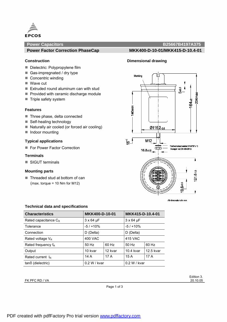
Power Capacitors B25667B4197A375 Power Factor Correction PhaseCap MKK400-D-10-01/MKK415-D-10.4-01
Edition 3. FK PFC RD / VA 20.10.05
Page 1 of 3
Construction Dimensional drawing
Dielectric: Polypropylene film Gas-impregnated / dry type Concentric winding Wave cut Extruded round aluminum can with stud Provided with ceramic discharge module Triple safety system
FeaturesThree phase, delta connected Self-healing technology Naturally air cooled (or forced air cooling) Indoor mounting
Typical applications For Power Factor Correction
TerminalsSIGUT terminals
Mounting parts Threaded stud at bottom of can
(max. torque = 10 Nm for M12)
Technical data and specifications
Characteristics MKK400-D-10-01 MKK415-D-10.4-01Rated capacitance CR 3 x 64 µF 3 x 64 µF
Tolerance -5 / +10% -5 / +10%
Connection D (Delta) D (Delta)
Rated voltage VR 400 VAC 415 VAC
Rated frequency fR 50 Hz 60 Hz 50 Hz 60 Hz
Output 10 kvar 12 kvar 10.4 kvar 12.5 kvar
Rated current IR 14 A 17 A 15 A 17 A
tan (dielectric) 0.2 W / kvar 0.2 W / kvar
PDF created with pdfFactory Pro trial version www.pdffactory.com
Power Capacitors B25667B4197A375 Power Factor Correction PhaseCap MKK400-D-10-01/MKK415-D-10.4-01
Edition 3. FK PFC RD / VA 20.10.05
Page 2 of 3
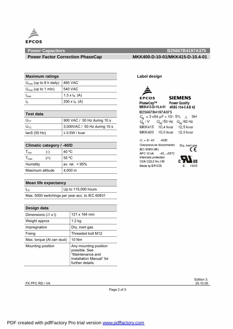
Maximum ratings Umax (up to 8 h daily) 460 VAC
Umax (up to 1 min) 540 VAC
Imax 1.3 x IR (A)
IS 200 x IR (A)
Test data UTT 900 VAC / 50 Hz during 10 s
UTC 3,000VAC / 50 Hz during 10 s
tan (50 Hz) 0.5W / kvar
Climatic category / -40/D Tmin (-) 40 ºC
Tmax (+) 55 ºC
Humidity av. rel. < 95%
Maximum altitude 4,000 m Mean life expectancy tLD Up to 115,000 hours
Max. 5000 switchings per year acc. to IEC 60831 Design data Dimensions ( x l) 121 x 164 mm
Weight approx 1.2 kg
Impregnation Dry, inert gas
Fixing Threaded bolt M12
Max. torque (Al can stud) 10 Nm
Mounting position Any mounting position possible. See �Maintenance and Installation Manual� for further details.
Label design
PDF created with pdfFactory Pro trial version www.pdffactory.com
Power Capacitors B25667B4197A375 Power Factor Correction PhaseCap MKK400-D-10-01/MKK415-D-10.4-01
Edition 3. FK PFC RD / VA 20.10.05
Page 3 of 3
Please read information about PFC capacitors and cautions as well as installation and maintenance instructions (Power Factor Correction Product Profile, actual version, and Installation and Maintenance Instructions for PFC-capacitors, available in the Internet) to ensure optimum performance and prevent products from failing, and in worst case, bursting and fire. Information given in the PFC-product profile and values given in the data sheet reflect typical specifications. You are kindly requested to approve our product specifications or request our approval for your specification before ordering.
EPCOS AG 2005. All Rights reserved. Reproduction, publication and dissemination of this data sheet, enclosures hereto and the information contained therein without EPCOS' prior express consent is prohibited. The information contained in this data sheet describes the type of component and shall not be considered as guaranteed characteristics. Purchase orders are subject to the General Conditions for the Supply of Products and Services of the Electrical and Electronics Industry recommended by the ZVEI (German Electrical and Electronic Manufacturers' Association), unless otherwise agreed.
TerminalsDegree of protection Isolated terminals, IP20
Max. torque 1.2 Nm
Terminal cross section 16 mm2 (5 AWG)
Maximum terminal current 50 A
Creepage distance 12.7 mm
Clearance 9.6 mm
Safety Mechanical safety Overpressure disconnector
Max. short circuit current (AFC: 10 kA)
Discharge resistor time 1 min (75 V)
Reference Standards IEC 60831-1/2, UL 810-5th edition
Certification: cUL file E238746
PDF created with pdfFactory Pro trial version www.pdffactory.com
Power Capacitors B25667B4207A375 Power Factor Correction PhaseCap MKK440-D-12.5-01/MKK480-D-15-01
Edition 3. FK PFC RD / VA 20.10.05
Page 1 of 3
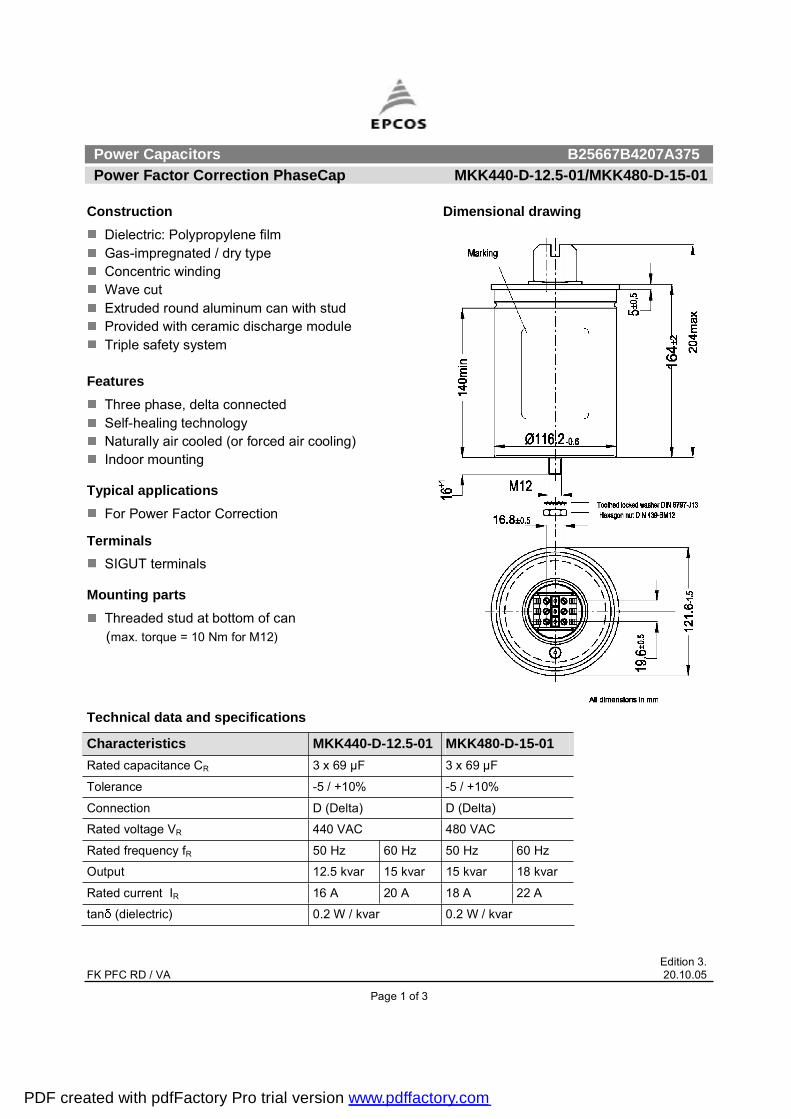
Construction Dimensional drawing
Dielectric: Polypropylene film Gas-impregnated / dry type Concentric winding Wave cut Extruded round aluminum can with stud Provided with ceramic discharge module Triple safety system
FeaturesThree phase, delta connected Self-healing technology Naturally air cooled (or forced air cooling) Indoor mounting
Typical applications For Power Factor Correction
TerminalsSIGUT terminals
Mounting parts Threaded stud at bottom of can
(max. torque = 10 Nm for M12)
Technical data and specifications
Characteristics MKK440-D-12.5-01 MKK480-D-15-01Rated capacitance CR 3 x 69 µF 3 x 69 µF
Tolerance -5 / +10% -5 / +10%
Connection D (Delta) D (Delta)
Rated voltage VR 440 VAC 480 VAC
Rated frequency fR 50 Hz 60 Hz 50 Hz 60 Hz
Output 12.5 kvar 15 kvar 15 kvar 18 kvar
Rated current IR 16 A 20 A 18 A 22 A
tan (dielectric) 0.2 W / kvar 0.2 W / kvar
PDF created with pdfFactory Pro trial version www.pdffactory.com
Power Capacitors B25667B4207A375 Power Factor Correction PhaseCap MKK440-D-12.5-01/MKK480-D-15-01
Edition 3. FK PFC RD / VA 20.10.05
Page 2 of 3
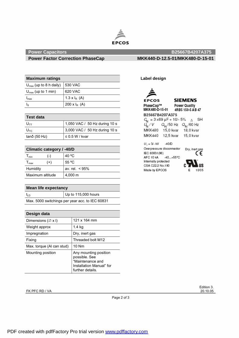
Maximum ratings Umax (up to 8 h daily) 530 VAC
Umax (up to 1 min) 620 VAC
Imax 1.3 x IR (A)
IS 200 x IR (A)
Test data UTT 1,050 VAC / 50 Hz during 10 s
UTC 3,000 VAC / 50 Hz during 10 s
tan (50 Hz) 0.5 W / kvar
Climatic category / -40/D Tmin (-) 40 ºC
Tmax (+) 55 ºC
Humidity av. rel. < 95%
Maximum altitude 4,000 m Mean life expectancy tLD Up to 115,000 hours
Max. 5000 switchings per year acc. to IEC 60831 Design data Dimensions ( x l) 121 x 164 mm
Weight approx 1.4 kg
Impregnation Dry, inert gas
Fixing Threaded bolt M12
Max. torque (Al can stud) 10 Nm
Mounting position Any mounting position possible. See �Maintenance and Installation Manual� for further details.
Label design
PDF created with pdfFactory Pro trial version www.pdffactory.com
Power Capacitors B25667B4207A375 Power Factor Correction PhaseCap MKK440-D-12.5-01/MKK480-D-15-01
Edition 3. FK PFC RD / VA 20.10.05
Page 3 of 3
Please read information about PFC capacitors and cautions as well as installation and maintenance instructions (Power Factor Correction Product Profile, actual version, and Installation and Maintenance Instructions for PFC-capacitors, available in the Internet) to ensure optimum performance and prevent products from failing, and in worst case, bursting and fire. Information given in the PFC-product profile and values given in the data sheet reflect typical specifications. You are kindly requested to approve our product specifications or request our approval for your specification before ordering.
EPCOS AG 2005. All Rights reserved. Reproduction, publication and dissemination of this data sheet, enclosures hereto and the information contained therein without EPCOS' prior express consent is prohibited. The information contained in this data sheet describes the type of component and shall not be considered as guaranteed characteristics. Purchase orders are subject to the General Conditions for the Supply of Products and Services of the Electrical and Electronics Industry recommended by the ZVEI (German Electrical and Electronic Manufacturers' Association), unless otherwise agreed.
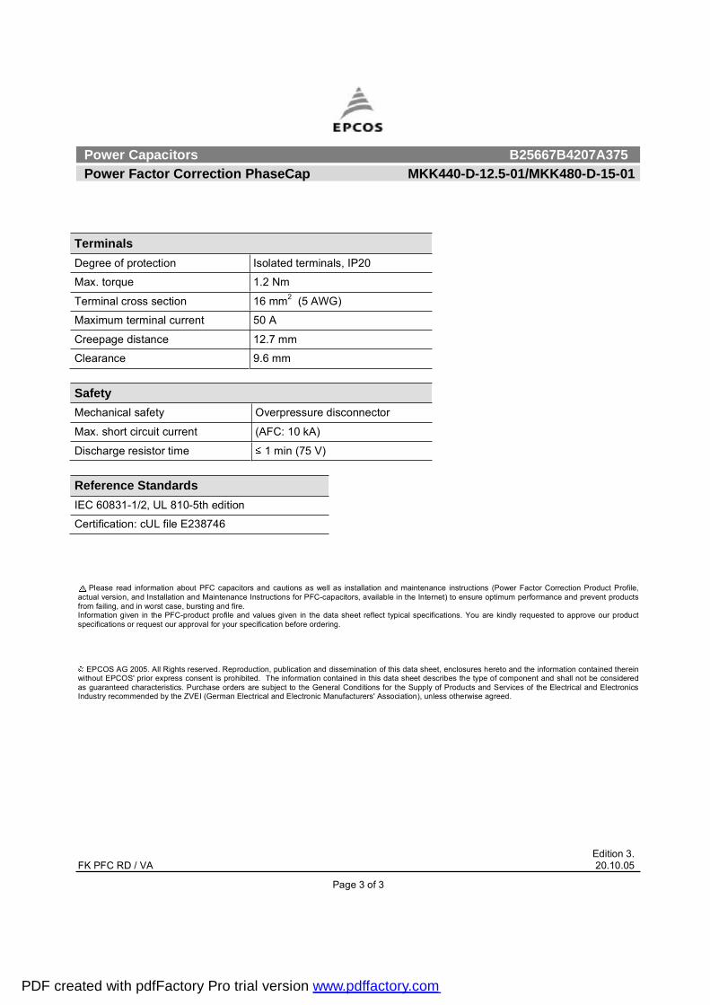
TerminalsDegree of protection Isolated terminals, IP20
Max. torque 1.2 Nm
Terminal cross section 16 mm2 (5 AWG)
Maximum terminal current 50 A
Creepage distance 12.7 mm
Clearance 9.6 mm
Safety Mechanical safety Overpressure disconnector
Max. short circuit current (AFC: 10 kA)
Discharge resistor time 1 min (75 V)
Reference Standards IEC 60831-1/2, UL 810-5th edition
Certification: cUL file E238746
PDF created with pdfFactory Pro trial version www.pdffactory.com

Power Capacitors B25667B4237A375 Power Factor Correction PhaseCap MKK415-D-12.5-01/MKK440-D-14.2-01
Edition 3. FK PFC RD / VA 20.10.05
Page 1 of 3
Construction Dimensional drawing
Dielectric: Polypropylene film Gas-impregnated / dry type Concentric winding Wave cut Extruded round aluminum can with stud Provided with ceramic discharge module Triple safety system
FeaturesThree phase, delta connected Self-healing technology Naturally air cooled (or forced air cooling) Indoor mounting
Typical applications For Power Factor Correction
TerminalsSIGUT terminals
Mounting parts Threaded stud at bottom of can
(max. torque = 10 Nm for M12)
Technical data and specifications
Characteristics MKK415-D-12.5-01 MKK440-D-14.2.-01Rated capacitance CR 3 x 77 µF 3 x 77 µF
Tolerance -5 / +10% -5 / +10%
Connection D (Delta) D (Delta)
Rated voltage VR 415 VAC 440 VAC
Rated frequency fR 50 Hz 60 Hz 50 Hz 60 Hz
Output 12.5 kvar 15 kvar 14.2 kvar 17 kvar
Rated current IR 17 A 21 A 19 A 22 A
tan (dielectric) 0.2 W / kvar 0.2 W / kvar
PDF created with pdfFactory Pro trial version www.pdffactory.com
Power Capacitors B25667B4237A375 Power Factor Correction PhaseCap MKK415-D-12.5-01/MKK440-D-14.2-01
Edition 3. FK PFC RD / VA 20.10.05
Page 2 of 3
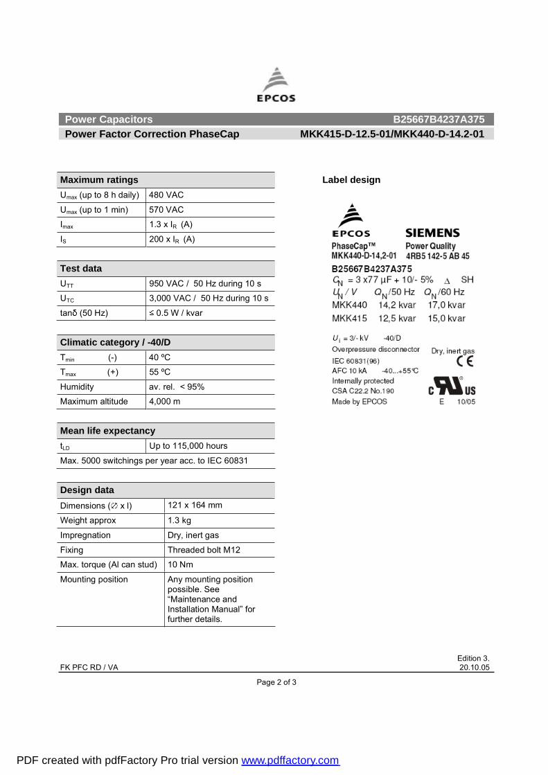
Maximum ratings Umax (up to 8 h daily) 480 VAC
Umax (up to 1 min) 570 VAC
Imax 1.3 x IR (A)
IS 200 x IR (A)
Test data UTT 950 VAC / 50 Hz during 10 s
UTC 3,000 VAC / 50 Hz during 10 s
tan (50 Hz) 0.5 W / kvar
Climatic category / -40/D Tmin (-) 40 ºC
Tmax (+) 55 ºC
Humidity av. rel. < 95%
Maximum altitude 4,000 m Mean life expectancy tLD Up to 115,000 hours
Max. 5000 switchings per year acc. to IEC 60831 Design data Dimensions ( x l) 121 x 164 mm
Weight approx 1.3 kg
Impregnation Dry, inert gas
Fixing Threaded bolt M12
Max. torque (Al can stud) 10 Nm
Mounting position Any mounting position possible. See �Maintenance and Installation Manual� for further details.
Label design
PDF created with pdfFactory Pro trial version www.pdffactory.com

Power Capacitors B25667B4237A375 Power Factor Correction PhaseCap MKK415-D-12.5-01/MKK440-D-14.2-01
Edition 3. FK PFC RD / VA 20.10.05
Page 3 of 3
Please read information about PFC capacitors and cautions as well as installation and maintenance instructions (Power Factor Correction Product Profile, actual version, and Installation and Maintenance Instructions for PFC-capacitors, available in the Internet) to ensure optimum performance and prevent products from failing, and in worst case, bursting and fire. Information given in the PFC-product profile and values given in the data sheet reflect typical specifications. You are kindly requested to approve our product specifications or request our approval for your specification before ordering.
EPCOS AG 2005. All Rights reserved. Reproduction, publication and dissemination of this data sheet, enclosures hereto and the information contained therein without EPCOS' prior express consent is prohibited. The information contained in this data sheet describes the type of component and shall not be considered as guaranteed characteristics. Purchase orders are subject to the General Conditions for the Supply of Products and Services of the Electrical and Electronics Industry recommended by the ZVEI (German Electrical and Electronic Manufacturers' Association), unless otherwise agreed.
TerminalsDegree of protection Isolated terminals, IP20
Max. torque 1.2 Nm
Terminal cross section 16 mm2 (5 AWG)
Maximum terminal current 50 A
Creepage distance 12.7 mm
Clearance 9.6 mm
Safety Mechanical safety Overpressure disconnector
Max. short circuit current (AFC: 10 kA)
Discharge resistor time 1 min (75 V)
Reference Standards IEC 60831-1/2, UL 810-5th edition
Certification: cUL file E238746
PDF created with pdfFactory Pro trial version www.pdffactory.com

Power Capacitors B25667B4247A375 Power Factor Correction MKK440-D-15-01
Edition 2. FK PFC RD / VA 20.10.05
Page 1 of 3
Construction Dimensional drawing
Dielectric: Polypropylene film Gas-impregnated / dry type Concentric winding Wave cut Extruded round aluminum can with stud Provided with ceramic discharge module Triple safety system
FeaturesThree phase, delta connected Self-healing technology Naturally air cooled (or forced air cooling) Indoor mounting
Typical applications For Power Factor Correction
TerminalsSIGUT terminals
Mounting parts Threaded stud at bottom of can
(max. torque = 10 Nm for M12)
Technical data and specifications
Characteristics Rated capacitance CR 3 x 83 µF
Tolerance -5 / +10%
Connection D (Delta)
Rated voltage VR 440 VAC
Rated frequency fR 50 Hz 60 Hz
Output 15 kvar 18 kvar
Rated current IR 20 A 24 A
tan (dielectric) 0.2 W / kvar
PDF created with pdfFactory Pro trial version www.pdffactory.com
Power Capacitors B25667B4247A375 Power Factor Correction MKK440-D-15-01
Edition 2. FK PFC RD / VA 20.10.05
Page 2 of 3
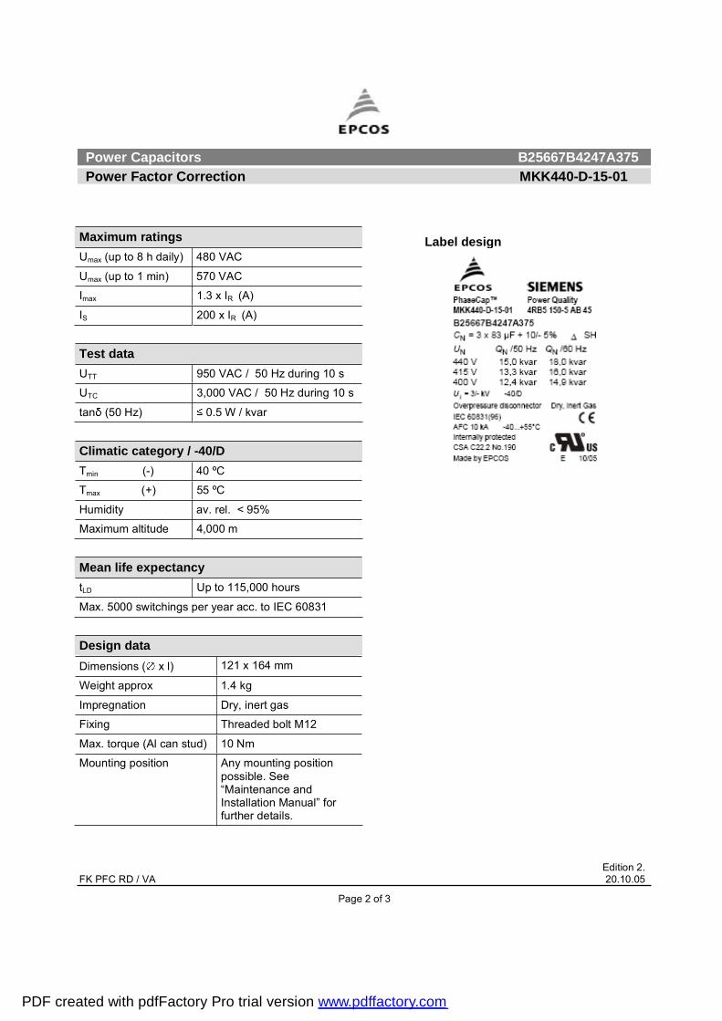
Maximum ratings Umax (up to 8 h daily) 480 VAC
Umax (up to 1 min) 570 VAC
Imax 1.3 x IR (A)
IS 200 x IR (A)
Test data UTT 950 VAC / 50 Hz during 10 s
UTC 3,000 VAC / 50 Hz during 10 s
tan (50 Hz) 0.5 W / kvar
Climatic category / -40/D Tmin (-) 40 ºC
Tmax (+) 55 ºC
Humidity av. rel. < 95%
Maximum altitude 4,000 m Mean life expectancy tLD Up to 115,000 hours
Max. 5000 switchings per year acc. to IEC 60831
Design data Dimensions ( x l) 121 x 164 mm
Weight approx 1.4 kg
Impregnation Dry, inert gas
Fixing Threaded bolt M12
Max. torque (Al can stud) 10 Nm
Mounting position Any mounting position possible. See �Maintenance and Installation Manual� for further details.
Label design
PDF created with pdfFactory Pro trial version www.pdffactory.com
Power Capacitors B25667B4247A375 Power Factor Correction MKK440-D-15-01
Edition 2. FK PFC RD / VA 20.10.05
Page 3 of 3
Please read information about PFC capacitors and cautions as well as installation and maintenance instructions (Power Factor Correction Product Profile, actual version, and Installation and Maintenance Instructions for PFC-capacitors, available in the Internet) to ensure optimum performance and prevent products from failing, and in worst case, bursting and fire. Information given in the PFC-product profile and values given in the data sheet reflect typical specifications. You are kindly requested to approve our product specifications or request our approval for your specification before ordering.
EPCOS AG 2005. All Rights reserved. Reproduction, publication and dissemination of this data sheet, enclosures hereto and the information contained therein without EPCOS' prior express consent is prohibited. The information contained in this data sheet describes the type of component and shall not be considered as guaranteed characteristics. Purchase orders are subject to the General Conditions for the Supply of Products and Services of the Electrical and Electronics Industry recommended by the ZVEI (German Electrical and Electronic Manufacturers' Association), unless otherwise agreed.
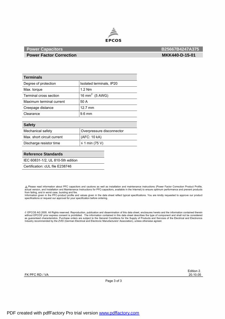
TerminalsDegree of protection Isolated terminals, IP20
Max. torque 1.2 Nm
Terminal cross section 16 mm2 (5 AWG)
Maximum terminal current 50 A
Creepage distance 12.7 mm
Clearance 9.6 mm
Safety Mechanical safety Overpressure disconnector
Max. short circuit current (AFC: 10 kA)
Discharge resistor time 1 min (75 V)
Reference Standards IEC 60831-1/2, UL 810-5th edition
Certification: cUL file E238746
PDF created with pdfFactory Pro trial version www.pdffactory.com
Power Capacitors B25667B4277A375 Power Factor Correction PhaseCap MKK440-D-16.7-01/MKK480-D-20-01
Edition 3. FK PFC RD / VA 20.10.05
Page 1 of 3
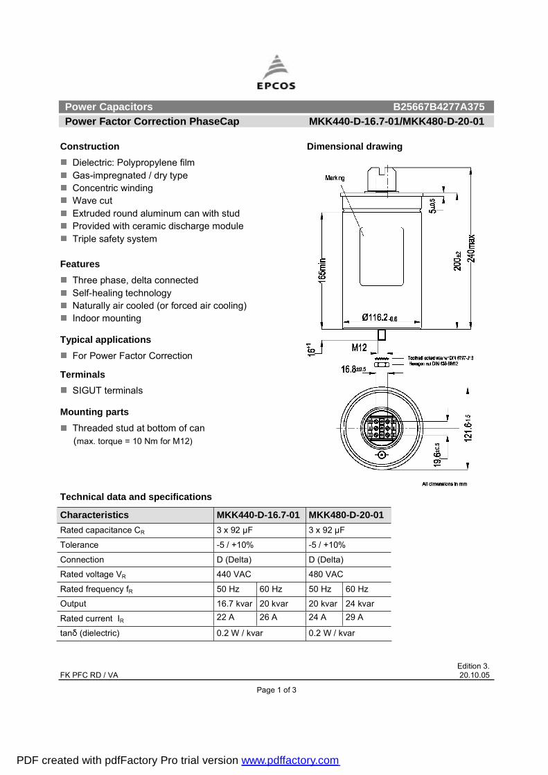
Construction Dimensional drawing
Dielectric: Polypropylene film Gas-impregnated / dry type Concentric winding Wave cut Extruded round aluminum can with stud Provided with ceramic discharge module Triple safety system
FeaturesThree phase, delta connected Self-healing technology Naturally air cooled (or forced air cooling) Indoor mounting
Typical applications For Power Factor Correction
TerminalsSIGUT terminals
Mounting parts Threaded stud at bottom of can
(max. torque = 10 Nm for M12)
Technical data and specifications
Characteristics MKK440-D-16.7-01 MKK480-D-20-01Rated capacitance CR 3 x 92 µF 3 x 92 µF
Tolerance -5 / +10% -5 / +10%
Connection D (Delta) D (Delta)
Rated voltage VR 440 VAC 480 VAC
Rated frequency fR 50 Hz 60 Hz 50 Hz 60 Hz
Output 16.7 kvar 20 kvar 20 kvar 24 kvar
Rated current IR 22 A 26 A 24 A 29 A
tan (dielectric) 0.2 W / kvar 0.2 W / kvar
PDF created with pdfFactory Pro trial version www.pdffactory.com
Power Capacitors B25667B4277A375 Power Factor Correction PhaseCap MKK440-D-16.7-01/MKK480-D-20-01
Edition 3. FK PFC RD / VA 20.10.05
Page 2 of 3
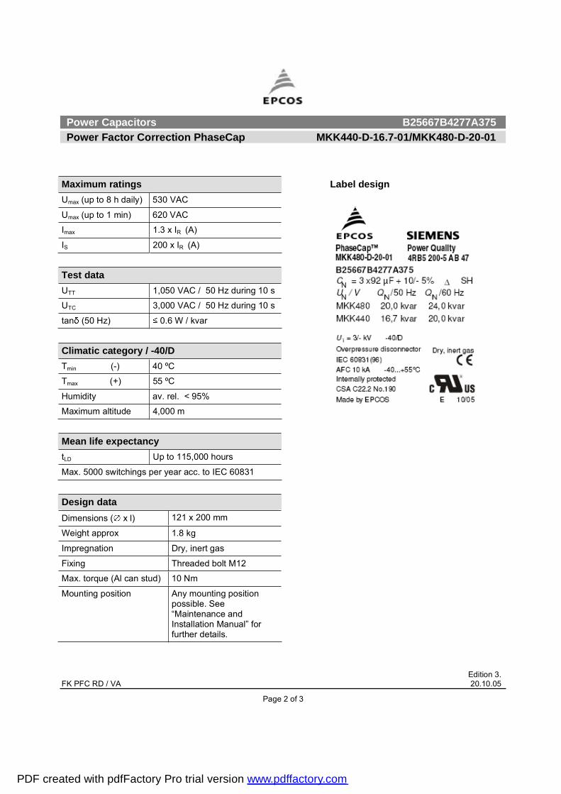
Maximum ratings Umax (up to 8 h daily) 530 VAC
Umax (up to 1 min) 620 VAC
Imax 1.3 x IR (A)
IS 200 x IR (A)
Test data UTT 1,050 VAC / 50 Hz during 10 s
UTC 3,000 VAC / 50 Hz during 10 s
tan (50 Hz) 0.6 W / kvar
Climatic category / -40/D Tmin (-) 40 ºC
Tmax (+) 55 ºC
Humidity av. rel. < 95%
Maximum altitude 4,000 m Mean life expectancy tLD Up to 115,000 hours
Max. 5000 switchings per year acc. to IEC 60831 Design data Dimensions ( x l) 121 x 200 mm
Weight approx 1.8 kg
Impregnation Dry, inert gas
Fixing Threaded bolt M12
Max. torque (Al can stud) 10 Nm
Mounting position Any mounting position possible. See �Maintenance and Installation Manual� for further details.
Label design
PDF created with pdfFactory Pro trial version www.pdffactory.com

Power Capacitors B25667B4277A375 Power Factor Correction PhaseCap MKK440-D-16.7-01/MKK480-D-20-01
Edition 3. FK PFC RD / VA 20.10.05
Page 3 of 3
Please read information about PFC capacitors and cautions as well as installation and maintenance instructions (Power Factor Correction Product Profile, actual version, and Installation and Maintenance Instructions for PFC-capacitors, available in the Internet) to ensure optimum performance and prevent products from failing, and in worst case, bursting and fire. Information given in the PFC-product profile and values given in the data sheet reflect typical specifications. You are kindly requested to approve our product specifications or request our approval for your specification before ordering.
EPCOS AG 2005. All Rights reserved. Reproduction, publication and dissemination of this data sheet, enclosures hereto and the information contained therein without EPCOS' prior express consent is prohibited. The information contained in this data sheet describes the type of component and shall not be considered as guaranteed characteristics. Purchase orders are subject to the General Conditions for the Supply of Products and Services of the Electrical and Electronics Industry recommended by the ZVEI (German Electrical and Electronic Manufacturers' Association), unless otherwise agreed.
TerminalsDegree of protection Isolated terminals, IP20
Max. torque 1.2 Nm
Terminal cross section 16 mm2 (5 AWG)
Maximum terminal current 50 A
Creepage distance 12.7 mm
Clearance 9.6 mm
Safety Mechanical safety Overpressure disconnector
Max. short circuit current (AFC: 10 kA)
Discharge resistor time 1 min (75 V)
Reference Standards IEC 60831-1/2, UL 810-5th edition
Certification: cUL file E238746
PDF created with pdfFactory Pro trial version www.pdffactory.com
Power Capacitors B25667B4347A375 Power Factor Correction MKK480-D-25-01
Edition 3. FK PFC RD / VA 30.11.05
Page 1 of 3
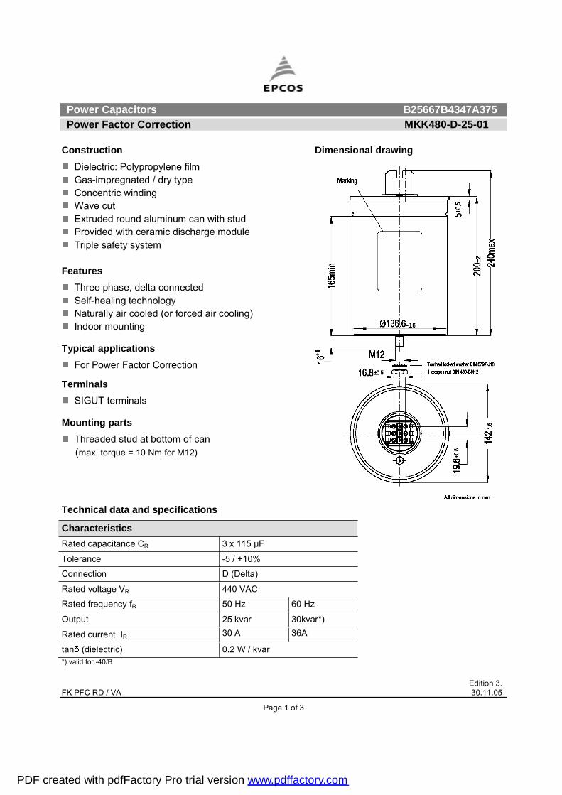
Construction Dimensional drawing
Dielectric: Polypropylene film Gas-impregnated / dry type Concentric winding Wave cut Extruded round aluminum can with stud Provided with ceramic discharge module Triple safety system
FeaturesThree phase, delta connected Self-healing technology Naturally air cooled (or forced air cooling) Indoor mounting
Typical applications For Power Factor Correction
TerminalsSIGUT terminals
Mounting parts Threaded stud at bottom of can
(max. torque = 10 Nm for M12)
Technical data and specifications
Characteristics Rated capacitance CR 3 x 115 µF
Tolerance -5 / +10%
Connection D (Delta)
Rated voltage VR 440 VAC
Rated frequency fR 50 Hz 60 Hz
Output 25 kvar 30kvar*)
Rated current IR 30 A 36A
tan (dielectric) 0.2 W / kvar *) valid for -40/B
PDF created with pdfFactory Pro trial version www.pdffactory.com
Power Capacitors B25667B4347A375 Power Factor Correction MKK480-D-25-01
Edition 3. FK PFC RD / VA 30.11.05
Page 2 of 3
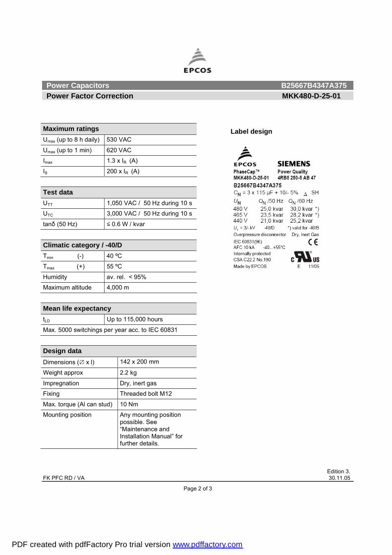
Maximum ratings Umax (up to 8 h daily) 530 VAC
Umax (up to 1 min) 620 VAC
Imax 1.3 x IR (A)
IS 200 x IR (A)
Test data UTT 1,050 VAC / 50 Hz during 10 s
UTC 3,000 VAC / 50 Hz during 10 s
tan (50 Hz) 0.6 W / kvar
Climatic category / -40/D Tmin (-) 40 ºC
Tmax (+) 55 ºC
Humidity av. rel. < 95%
Maximum altitude 4,000 m Mean life expectancy tLD Up to 115,000 hours
Max. 5000 switchings per year acc. to IEC 60831
Design data Dimensions ( x l) 142 x 200 mm
Weight approx 2.2 kg
Impregnation Dry, inert gas
Fixing Threaded bolt M12
Max. torque (Al can stud) 10 Nm
Mounting position Any mounting position possible. See �Maintenance and Installation Manual� for further details.
Label design
PDF created with pdfFactory Pro trial version www.pdffactory.com

Power Capacitors B25667B4347A375 Power Factor Correction MKK480-D-25-01
Edition 3. FK PFC RD / VA 30.11.05
Page 3 of 3
Please read information about PFC capacitors and cautions as well as installation and maintenance instructions (Power Factor Correction Product Profile, actual version, and Installation and Maintenance Instructions for PFC-capacitors, available in the Internet) to ensure optimum performance and prevent products from failing, and in worst case, bursting and fire. Information given in the PFC-product profile and values given in the data sheet reflect typical specifications. You are kindly requested to approve our product specifications or request our approval for your specification before ordering.
EPCOS AG 2005. All Rights reserved. Reproduction, publication and dissemination of this data sheet, enclosures hereto and the information contained therein without EPCOS' prior express consent is prohibited. The information contained in this data sheet describes the type of component and shall not be considered as guaranteed characteristics. Purchase orders are subject to the General Conditions for the Supply of Products and Services of the Electrical and Electronics Industry recommended by the ZVEI (German Electrical and Electronic Manufacturers' Association), unless otherwise agreed.
TerminalsDegree of protection Isolated terminals, IP20
Max. torque 1.2 Nm
Terminal cross section 16 mm2 (5 AWG)
Maximum terminal current 50 A
Creepage distance 12.7 mm
Clearance 9.6 mm
Safety Mechanical safety Overpressure disconnector
Max. short circuit current (AFC: 10 kA)
Discharge resistor time 1 min (75 V)
Reference Standards IEC 60831-1/2, UL 810-5th edition
Certification: cUL file E238746
PDF created with pdfFactory Pro trial version www.pdffactory.com

Power Capacitors B25667B4417A365Power Factor Correction MKK480-D-30-01
Edition 1. FK PFC RD / VA 10.03.05
Construction Dimensional drawingDielectric: Polypropylene film Gas-impregnated / dry type Concentric winding Wave cut Extruded round aluminum can with stud Provided with ceramic discharge module Triple safety system
FeaturesThree phase, delta connectedSelf-healing technology Naturally air cooled (or forced air cooling)Indoor mounting
Typical applicationsFor Power Factor Correction
TerminalsSIGUT terminals
Mounting partsThreaded stud at bottom of can
(max. torque = 10 Nm for M12)
Technical data and specifications
CharacteristicsRated capacitance CR 3 x 138 µF
Tolerance -5 / +10%
Connection D (Delta)
Rated voltage VR 440 VAC
Rated frequency fR 50 Hz 60 Hz
Output 30 kvar --
Rated current IR 36 A --
tan (dielectric) 0.2 W / kvar
Page 1 of 3
PDF created with pdfFactory Pro trial version www.pdffactory.com

Power Capacitors B25667B4417A365Power Factor Correction MKK480-D-30-01
Edition 1.
Label design Maximum ratings Umax (up to 8 h daily) 530 VAC
Umax (up to 1 min) 620 VAC
Imax 1.3 x IR (A)
IS 200 x IR (A)
Test data UTT 1,050 VAC / 50 Hz during 10 s
UTC 3,000 VAC / 50 Hz during 10 s
tan (50 Hz) 0.6 W / kvar
Climatic category / -40/CTmin (-) 40 ºC
Tmax (+) 50 ºC
Humidity av. rel. < 95%
Maximum altitude 4,000 m
Mean life expectancytLD Up to 100,000 hours
Max. 5000 switchings per year acc. to IEC 60831
Design data Dimensions ( x l) 142 x 200 mm
Weight approx 2.4 kg
Impregnation Dry, inert gas
Fixing Threaded bolt M12
Max. torque (Al can stud) 10 Nm
Mounting position Any mounting position possible. See �Maintenance and Installation Manual� for further details.
FK PFC RD / VA 10.03.05
Page 2 of 3
PDF created with pdfFactory Pro trial version www.pdffactory.com

Power Capacitors B25667B4417A365Power Factor Correction MKK480-D-30-01
Edition 1.
TerminalsDegree of protection Isolated terminals, IP20
Max. torque 1.2 Nm
Terminal cross section 16 mm2 (5 AWG)
Maximum terminal current 50 A
Creepage distance 12.7 mm
Clearance 9.6 mm
SafetyMechanical safety Overpressure disconnector
Max. short circuit current (AFC: 10 kA)
Discharge resistor time 1 min (75 V)
Reference standards IEC 60831-1/2, UL 810-5th edition
Certification: cUL file E238746
Please read information about PFC capacitors and cautions as well as installation and maintenance instructions (Power Factor Correction Product Profile,actual version, and Installation and Maintenance Instructions for PFC-capacitors, available in the Internet) to ensure optimum performance and prevent productsfrom failing, and in worst case, bursting and fire.Information given in the PFC-product profile and values given in the data sheet reflect typical specifications. You are kindly requested to approve our productspecifications or request our approval for your specification before ordering.
M EPCOS AG 2005. All Rights reserved. Reproduction, publication and dissemination of this data sheet, enclosures hereto and the information contained thereinwithout EPCOS' prior express consent is prohibited. The information contained in this data sheet describes the type of component and shall not be consideredas guaranteed characteristics. Purchase orders are subject to the General Conditions for the Supply of Products and Services of the Electrical and ElectronicsIndustry recommended by the ZVEI (German Electrical and Electronic Manufacturers' Association), unless otherwise agreed.
FK PFC RD / VA 10.03.05
Page 3 of 3
PDF created with pdfFactory Pro trial version www.pdffactory.com
Power Capacitors B25667B4417A375 Power Factor Correction MKK440-D-25-01
Edition 2. FK PFC RD / VA 20.10.05
Page 1 of 3
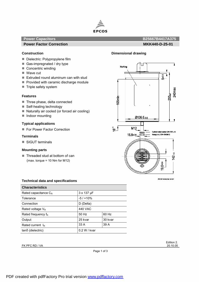
Construction Dimensional drawing
Dielectric: Polypropylene film Gas-impregnated / dry type Concentric winding Wave cut Extruded round aluminum can with stud Provided with ceramic discharge module Triple safety system
FeaturesThree phase, delta connected Self-healing technology Naturally air cooled (or forced air cooling) Indoor mounting
Typical applications For Power Factor Correction
TerminalsSIGUT terminals
Mounting parts Threaded stud at bottom of can
(max. torque = 10 Nm for M12)
Technical data and specifications
Characteristics Rated capacitance CR 3 x 137 µF
Tolerance -5 / +10%
Connection D (Delta)
Rated voltage VR 440 VAC
Rated frequency fR 50 Hz 60 Hz
Output 25 kvar 30 kvar
Rated current IR 33 A 39 A
tan (dielectric) 0.2 W / kvar
PDF created with pdfFactory Pro trial version www.pdffactory.com

Power Capacitors B25667B4417A375 Power Factor Correction MKK440-D-25-01
Edition 2. FK PFC RD / VA 20.10.05
Page 2 of 3
Maximum ratings Umax (up to 8 h daily) 480 VAC
Umax (up to 1 min) 570 VAC
Imax 1.3 x IR (A)
IS 200 x IR (A)
Test data UTT 950 VAC / 50 Hz during 10 s
UTC 3,000 VAC / 50 Hz during 10 s
tan (50 Hz) 0.6 W / kvar
Climatic category / -40/D Tmin (-) 40 ºC
Tmax (+) 55 ºC
Humidity av. rel. < 95%
Maximum altitude 4,000 m Mean life expectancy tLD Up to 115,000 hours
Max. 5000 switchings per year acc. to IEC 60831
Design data Dimensions ( x l) 142 x 200 mm
Weight approx 2.0 kg
Impregnation Dry, inert gas
Fixing Threaded bolt M12
Max. torque (Al can stud) 10 Nm
Mounting position Any mounting position possible. See �Maintenance and Installation Manual� for further details.
Label design
PDF created with pdfFactory Pro trial version www.pdffactory.com

Power Capacitors B25667B4417A375 Power Factor Correction MKK440-D-25-01
Edition 2. FK PFC RD / VA 20.10.05
Page 3 of 3
Please read information about PFC capacitors and cautions as well as installation and maintenance instructions (Power Factor Correction Product Profile, actual version, and Installation and Maintenance Instructions for PFC-capacitors, available in the Internet) to ensure optimum performance and prevent products from failing, and in worst case, bursting and fire. Information given in the PFC-product profile and values given in the data sheet reflect typical specifications. You are kindly requested to approve our product specifications or request our approval for your specification before ordering.
EPCOS AG 2005. All Rights reserved. Reproduction, publication and dissemination of this data sheet, enclosures hereto and the information contained therein without EPCOS' prior express consent is prohibited. The information contained in this data sheet describes the type of component and shall not be considered as guaranteed characteristics. Purchase orders are subject to the General Conditions for the Supply of Products and Services of the Electrical and Electronics Industry recommended by the ZVEI (German Electrical and Electronic Manufacturers' Association), unless otherwise agreed.
TerminalsDegree of protection Isolated terminals, IP20
Max. torque 1.2 Nm
Terminal cross section 16 mm2 (5 AWG)
Maximum terminal current 50 A
Creepage distance 12.7 mm
Clearance 9.6 mm
Safety Mechanical safety Overpressure disconnector
Max. short circuit current (AFC: 10 kA)
Discharge resistor time 1 min (75 V)
Reference Standards IEC 60831-1/2, UL 810-5th edition
Certification: cUL file E238746
PDF created with pdfFactory Pro trial version www.pdffactory.com

Power Capacitors B25667B4467A375 Power Factor Correction PhaseCap MKK415-D-25-01/MKK440-D-28.1-01
Edition 3. FK PFC RD / VA 20.10.05
Page 1 of 3
Construction Dimensional drawing
Dielectric: Polypropylene film Gas-impregnated / dry type Concentric winding Wave cut Extruded round aluminum can with stud Provided with ceramic discharge module Triple safety system
FeaturesThree phase, delta connected Self-healing technology Naturally air cooled (or forced air cooling) Indoor mounting
Typical applications For Power Factor Correction
TerminalsSIGUT terminals
Mounting parts Threaded stud at bottom of can
(max. torque = 10 Nm for M12)
Technical data and specifications
Characteristics MKK415-D-25-01 MKK440-D-28.1-01Rated capacitance CR 3 x 154 µF 3 x 154 µF
Tolerance -5 / +10% -5 / +10%
Connection D (Delta) D (Delta)
Rated voltage VR 415 VAC 440 VAC
Rated frequency fR 50 Hz 60 Hz 50 Hz 60 Hz
Output 25 kvar -- 28.1 kvar --
Rated current IR 35 A -- 37 A --
tan (dielectric) 0.2 W / kvar 0.2 W / kvar
PDF created with pdfFactory Pro trial version www.pdffactory.com

Power Capacitors B25667B4467A375 Power Factor Correction PhaseCap MKK415-D-25-01/MKK440-D-28.1-01
Edition 3. FK PFC RD / VA 20.10.05
Page 2 of 3
Maximum ratings Umax (up to 8 h daily) 480 VAC
Umax (up to 1 min) 570 VAC
Imax 1.3 x IR (A)
IS 200 x IR (A)
Test data UTT 950 VAC / 50 Hz during 10 s
UTC 3,000 VAC / 50 Hz during 10 s
tan (50 Hz) 0.7 W / kvar
Climatic category / -40/D Tmin (-) 40 ºC
Tmax (+) 55 ºC
Humidity av. rel. < 95%
Maximum altitude 4,000 m Mean life expectancy tLD Up to 100,000 hours
Max. 5000 switchings per year acc. to IEC 60831 Design data Dimensions ( x l) 142 x 200 mm
Weight approx 2.1 kg
Impregnation Dry, inert gas
Fixing Threaded bolt M12
Max. torque (Al can stud) 10 Nm
Mounting position Any mounting position possible. See �Maintenance and Installation Manual� for further details.
Label design
PDF created with pdfFactory Pro trial version www.pdffactory.com

Power Capacitors B25667B4467A375 Power Factor Correction PhaseCap MKK415-D-25-01/MKK440-D-28.1-01
Edition 3. FK PFC RD / VA 20.10.05
Page 3 of 3
Please read information about PFC capacitors and cautions as well as installation and maintenance instructions (Power Factor Correction Product Profile, actual version, and Installation and Maintenance Instructions for PFC-capacitors, available in the Internet) to ensure optimum performance and prevent products from failing, and in worst case, bursting and fire. Information given in the PFC-product profile and values given in the data sheet reflect typical specifications. You are kindly requested to approve our product specifications or request our approval for your specification before ordering.
EPCOS AG 2005. All Rights reserved. Reproduction, publication and dissemination of this data sheet, enclosures hereto and the information contained therein without EPCOS' prior express consent is prohibited. The information contained in this data sheet describes the type of component and shall not be considered as guaranteed characteristics. Purchase orders are subject to the General Conditions for the Supply of Products and Services of the Electrical and Electronics Industry recommended by the ZVEI (German Electrical and Electronic Manufacturers' Association), unless otherwise agreed.
TerminalsDegree of protection Isolated terminals, IP20
Max. torque 1.2 Nm
Terminal cross section 16 mm2 (5 AWG)
Maximum terminal current 50 A
Creepage distance 12.7 mm
Clearance 9.6 mm
Safety Mechanical safety Overpressure disconnector
Max. short circuit current (AFC: 10 kA)
Discharge resistor time 1 min (75 V)
Reference Standards IEC 60831-1/2, UL 810-5th edition
Certification: cUL file E238746
PDF created with pdfFactory Pro trial version www.pdffactory.com
Power Capacitors B25667B5127A375 Power Factor Correction PhaseCap MKK415-D-6.2-01/MKK480-D-8.3-01/
MKK525-D-10-01
Edition 3. FK PFC RD / VA 20.10.05
Page 1 of 3
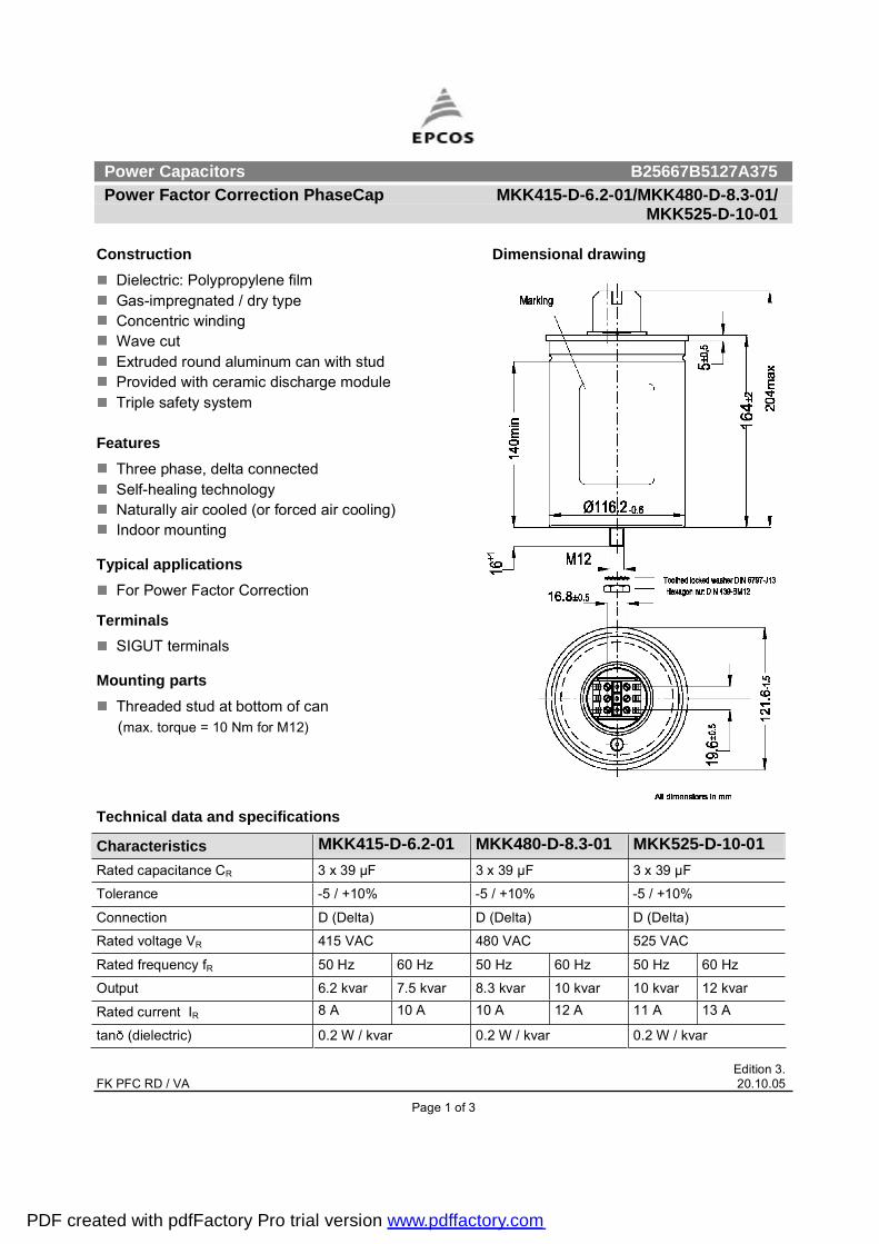
Construction Dimensional drawing
Dielectric: Polypropylene film Gas-impregnated / dry type Concentric winding Wave cut Extruded round aluminum can with stud Provided with ceramic discharge module Triple safety system
FeaturesThree phase, delta connected Self-healing technology Naturally air cooled (or forced air cooling) Indoor mounting
Typical applications For Power Factor Correction
TerminalsSIGUT terminals
Mounting parts Threaded stud at bottom of can
(max. torque = 10 Nm for M12)
Technical data and specifications
Characteristics MKK415-D-6.2-01 MKK480-D-8.3-01 MKK525-D-10-01Rated capacitance CR 3 x 39 µF 3 x 39 µF 3 x 39 µF
Tolerance -5 / +10% -5 / +10% -5 / +10%
Connection D (Delta) D (Delta) D (Delta)
Rated voltage VR 415 VAC 480 VAC 525 VAC
Rated frequency fR 50 Hz 60 Hz 50 Hz 60 Hz 50 Hz 60 Hz
Output 6.2 kvar 7.5 kvar 8.3 kvar 10 kvar 10 kvar 12 kvar
Rated current IR 8 A 10 A 10 A 12 A 11 A 13 A
tan (dielectric) 0.2 W / kvar 0.2 W / kvar 0.2 W / kvar
PDF created with pdfFactory Pro trial version www.pdffactory.com

Power Capacitors B25667B5127A375 Power Factor Correction PhaseCap MKK415-D-6.2-01/MKK480-D-8.3-01/
MKK525-D-10-01
Edition 3. FK PFC RD / VA 20.10.05
Page 2 of 3
Maximum ratings Umax (up to 8 h daily) 580 VAC
Umax (up to 1 min) 680 VAC
Imax 1.3 x IR (A)
IS 200 x IR (A)
Test data UTT 1,150 VAC / 50 Hz during 10 s
UTC 3,000 VAC / 50 Hz during 10 s
tan (50 Hz) 0.5 W / kvar
Climatic category / -40/D Tmin (-) 40 ºC
Tmax (+) 55 ºC
Humidity av. rel. < 95%
Maximum altitude 4,000 m Mean life expectancy tLD Up to 115,000 hours
Max. 5000 switchings per year acc. to IEC 60831 Design data Dimensions ( x l) 121 x 164 mm
Weight approx 1.2 kg
Impregnation Dry, inert gas
Fixing Threaded bolt M12
Max. torque (Al can stud) 10 Nm
Mounting position Any mounting position possible. See �Maintenance and Installation Manual� for further details.
Label design
PDF created with pdfFactory Pro trial version www.pdffactory.com
Power Capacitors B25667B5127A375 Power Factor Correction PhaseCap MKK415-D-6.2-01/MKK480-D-8.3-01/
MKK525-D-10-01
Edition 3. FK PFC RD / VA 20.10.05
Page 3 of 3
Please read information about PFC capacitors and cautions as well as installation and maintenance instructions (Power Factor Correction Product Profile, actual version, and Installation and Maintenance Instructions for PFC-capacitors, available in the Internet) to ensure optimum performance and prevent products from failing, and in worst case, bursting and fire. Information given in the PFC-product profile and values given in the data sheet reflect typical specifications. You are kindly requested to approve our product specifications or request our approval for your specification before ordering.
EPCOS AG 2005. All Rights reserved. Reproduction, publication and dissemination of this data sheet, enclosures hereto and the information contained therein without EPCOS' prior express consent is prohibited. The information contained in this data sheet describes the type of component and shall not be considered as guaranteed characteristics. Purchase orders are subject to the General Conditions for the Supply of Products and Services of the Electrical and Electronics Industry recommended by the ZVEI (German Electrical and Electronic Manufacturers' Association), unless otherwise agreed.
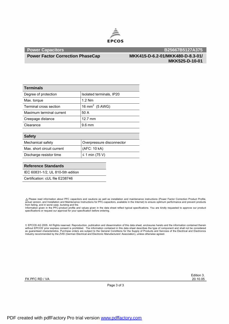
TerminalsDegree of protection Isolated terminals, IP20
Max. torque 1.2 Nm
Terminal cross section 16 mm2 (5 AWG)
Maximum terminal current 50 A
Creepage distance 12.7 mm
Clearance 9.6 mm
Safety Mechanical safety Overpressure disconnector
Max. short circuit current (AFC: 10 kA)
Discharge resistor time 1 min (75 V)
Reference Standards IEC 60831-1/2, UL 810-5th edition
Certification: cUL file E238746
PDF created with pdfFactory Pro trial version www.pdffactory.com
Power Capacitors B25667B5177A375 Power Factor Correction PhaseCap MKK480-D-12.5-01/MKK525-D-15-01
Edition 3. FK PFC RD / VA 20.10.05
Page 1 of 3
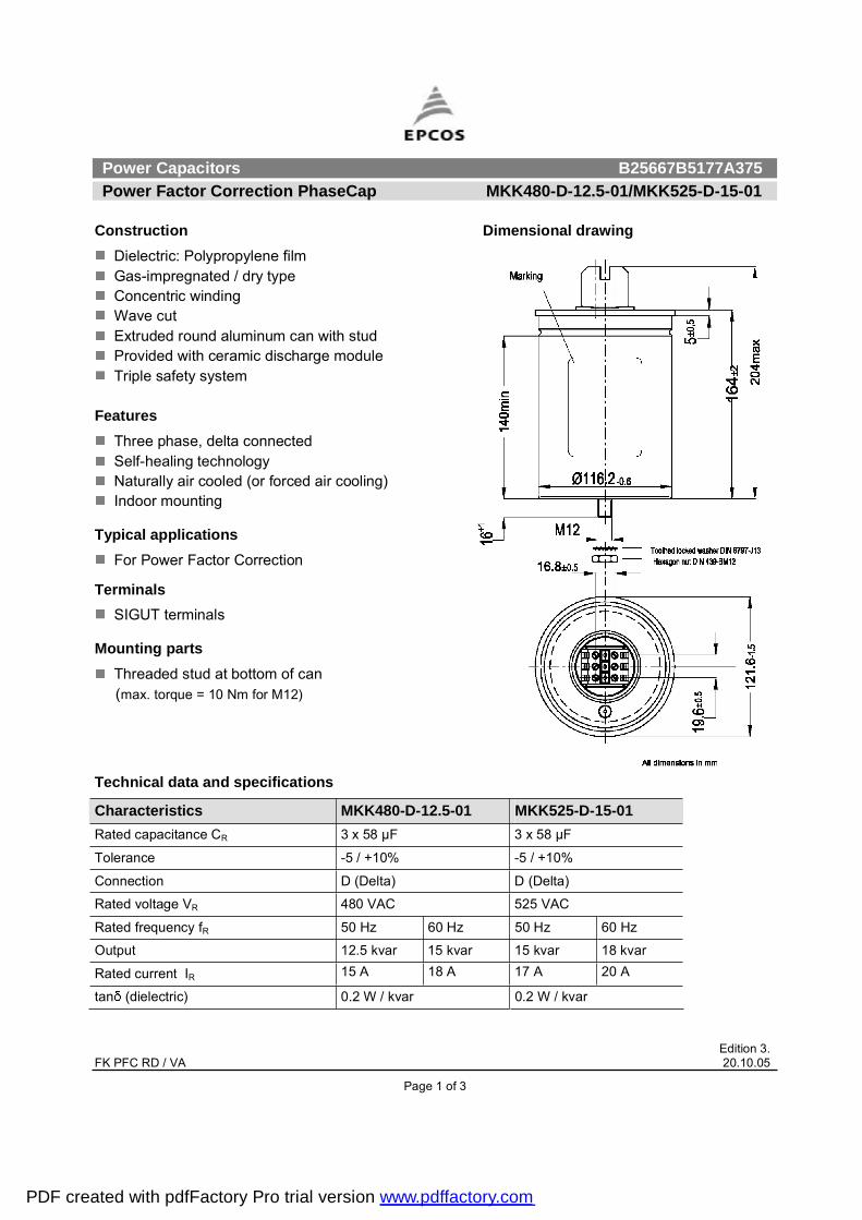
Construction Dimensional drawing
Dielectric: Polypropylene film Gas-impregnated / dry type Concentric winding Wave cut Extruded round aluminum can with stud Provided with ceramic discharge module Triple safety system
FeaturesThree phase, delta connected Self-healing technology Naturally air cooled (or forced air cooling) Indoor mounting
Typical applications For Power Factor Correction
TerminalsSIGUT terminals
Mounting parts Threaded stud at bottom of can
(max. torque = 10 Nm for M12)
Technical data and specifications
Characteristics MKK480-D-12.5-01 MKK525-D-15-01Rated capacitance CR 3 x 58 µF 3 x 58 µF
Tolerance -5 / +10% -5 / +10%
Connection D (Delta) D (Delta)
Rated voltage VR 480 VAC 525 VAC
Rated frequency fR 50 Hz 60 Hz 50 Hz 60 Hz
Output 12.5 kvar 15 kvar 15 kvar 18 kvar
Rated current IR 15 A 18 A 17 A 20 A
tan (dielectric) 0.2 W / kvar 0.2 W / kvar
PDF created with pdfFactory Pro trial version www.pdffactory.com

Power Capacitors B25667B5177A375 Power Factor Correction PhaseCap MKK480-D-12.5-01/MKK525-D-15-01
Edition 3. FK PFC RD / VA 20.10.05
Page 2 of 3
Maximum ratings Umax (up to 8 h daily) 580 VAC
Umax (up to 1 min) 680 VAC
Imax 1.3 x IR (A)
IS 200 x IR (A)
Test data UTT 1,150 VAC / 50 Hz during 10 s
UTC 3,000 VAC / 50 Hz during 10 s
tan (50 Hz) 0.5 W / kvar
Climatic category / -40/D Tmin (-) 40 ºC
Tmax (+) 55 ºC
Humidity av. rel. < 95%
Maximum altitude 4,000 m Mean life expectancy tLD Up to 115,000 hours
Max. 5000 switchings per year acc. to IEC 60831 Design data Dimensions ( x l) 121 x 164 mm
Weight approx 1.5 kg
Impregnation Dry, inert gas
Fixing Threaded bolt M12
Max. torque (Al can stud) 10 Nm
Mounting position Any mounting position possible. See �Maintenance and Installation Manual� for further details.
Label design
PDF created with pdfFactory Pro trial version www.pdffactory.com
Power Capacitors B25667B5177A375 Power Factor Correction PhaseCap MKK480-D-12.5-01/MKK525-D-15-01
Edition 3. FK PFC RD / VA 20.10.05
Page 3 of 3
Please read information about PFC capacitors and cautions as well as installation and maintenance instructions (Power Factor Correction Product Profile, actual version, and Installation and Maintenance Instructions for PFC-capacitors, available in the Internet) to ensure optimum performance and prevent products from failing, and in worst case, bursting and fire. Information given in the PFC-product profile and values given in the data sheet reflect typical specifications. You are kindly requested to approve our product specifications or request our approval for your specification before ordering.
EPCOS AG 2005. All Rights reserved. Reproduction, publication and dissemination of this data sheet, enclosures hereto and the information contained therein without EPCOS' prior express consent is prohibited. The information contained in this data sheet describes the type of component and shall not be considered as guaranteed characteristics. Purchase orders are subject to the General Conditions for the Supply of Products and Services of the Electrical and Electronics Industry recommended by the ZVEI (German Electrical and Electronic Manufacturers' Association), unless otherwise agreed.
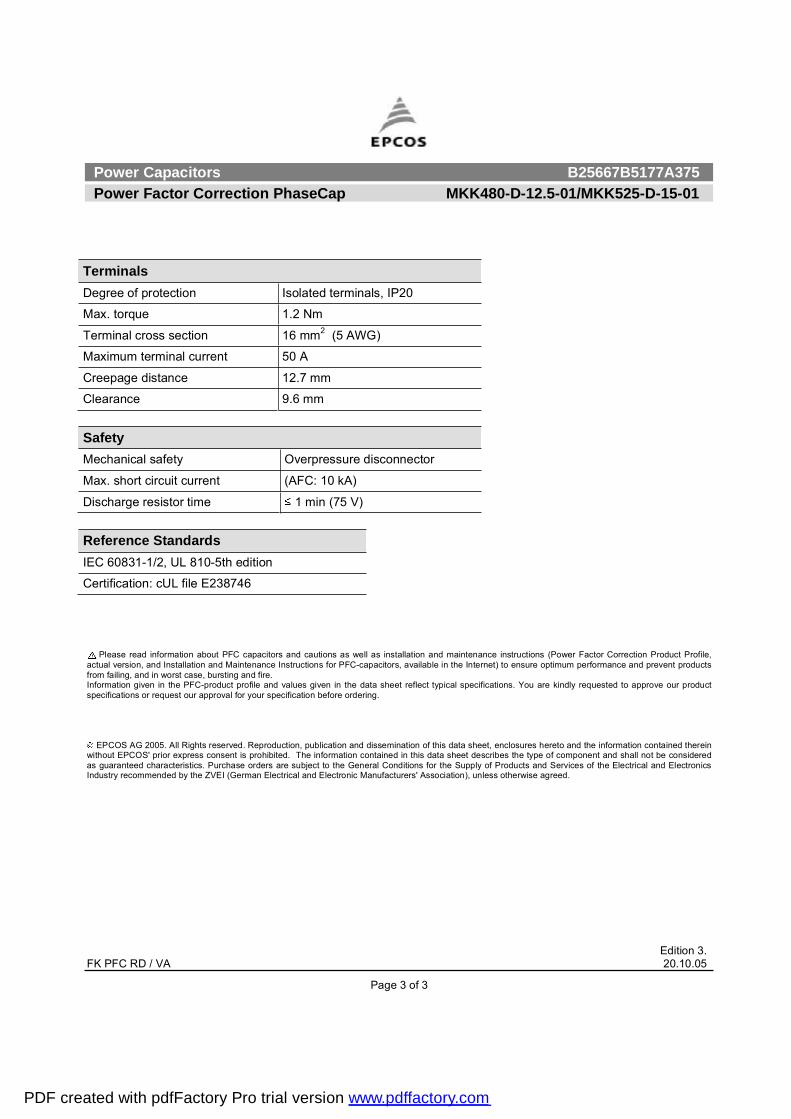
TerminalsDegree of protection Isolated terminals, IP20
Max. torque 1.2 Nm
Terminal cross section 16 mm2 (5 AWG)
Maximum terminal current 50 A
Creepage distance 12.7 mm
Clearance 9.6 mm
Safety Mechanical safety Overpressure disconnector
Max. short circuit current (AFC: 10 kA)
Discharge resistor time 1 min (75 V)
Reference Standards IEC 60831-1/2, UL 810-5th edition
Certification: cUL file E238746
PDF created with pdfFactory Pro trial version www.pdffactory.com
б©»® Ý¿°¿½·¬±® ÞîëêêéÞëîíéßíéë
б©»® Ú¿½¬±® ݱ®®»½¬·±² ÓÕÕìèðóÜóïêòéóðï ñ ÓÕÕëîëóÜóîðóðï
Û¼·¬·±² îòÚÕ ÐÚÝ ÎÜ ñ Êß îðòïðòðë
п¹» ï ±º í
ݱ²¬®«½¬·±² Ü·³»²·±²¿´ ¼®¿©·²¹
Ü·»´»½¬®·½æ б´§°®±°§´»²» º·´³
Ù¿ó·³°®»¹²¿¬»¼ ñ ¼®§ ¬§°»
ݱ²½»²¬®·½ ©·²¼·²¹
É¿ª» ½«¬
Û¨¬®«¼»¼ ®±«²¼ ¿´«³·²«³ ½¿² ©·¬¸ ¬«¼
Ю±ª·¼»¼ ©·¬¸ ½»®¿³·½ ¼·½¸¿®¹» ³±¼«´»
Ì®·°´» ¿º»¬§ §¬»³
Ú»¿¬«®»
̸®»» °¸¿»ô ¼»´¬¿ ½±²²»½¬»¼
Í»´ºó¸»¿´·²¹ ¬»½¸²±´±¹§
Ò¿¬«®¿´´§ ¿·® ½±±´»¼ ø±® º±®½»¼ ¿·® ½±±´·²¹÷
ײ¼±±® ³±«²¬·²¹
̧°·½¿´ ¿°°´·½¿¬·±²
Ú±® б©»® Ú¿½¬±® ݱ®®»½¬·±²
Ì»®³·²¿´
Í×ÙËÌ ¬»®³·²¿´
Ó±«²¬·²¹ °¿®¬
̸®»¿¼»¼ ¬«¼ ¿¬ ¾±¬¬±³ ±º ½¿²
ø³¿¨ò ¬±®¯«» ã ïð Ò³ º±® Óïî÷
Ì»½¸²·½¿´ ¼¿¬¿ ¿²¼ °»½·º·½¿¬·±²
ݸ¿®¿½¬»®·¬·½ ÓÕÕìèðóÜóïêòéóðï ÓÕÕëîëóÜóîðóðï
כּ¼ ½¿°¿½·¬¿²½» ÝÎ í ¨ éé kÚ í ¨ éé kÚ
̱´»®¿²½» óë ñ õïðû óë ñ õïðû
ݱ²²»½¬·±² Ü øÜ»´¬¿÷ Ü øÜ»´¬¿÷
כּ¼ ª±´¬¿¹» ÊÎ ìèð ÊßÝ ëîë ÊßÝ
כּ¼ º®»¯«»²½§ ºÎ ëð ئ êð ئ ëð ئ êð ئ
Ñ«¬°«¬ ïêòé µª¿® î𠵪¿® î𠵪¿® îì µª¿®
כּ¼ ½«®®»²¬ ×Î îð ß îì ß îî ß îê ß
¬¿² ø¼·»´»½¬®·½÷ ðòî É ñ µª¿® ðòî É ñ µª¿®
PDF created with pdfFactory Pro trial version www.pdffactory.com
б©»® Ý¿°¿½·¬±® ÞîëêêéÞëîíéßíéë
б©»® Ú¿½¬±® ݱ®®»½¬·±² ÓÕÕìèðóÜóïêòéóðï ñ ÓÕÕëîëóÜóîðóðï
Û¼·¬·±² îòÚÕ ÐÚÝ ÎÜ ñ Êß îðòïðòðë
п¹» î ±º í
Ó¿¨·³«³ ®¿¬·²¹
˳¿¨ ø«° ¬± è ¸ ¼¿·´§÷ ëèð ÊßÝ
˳¿¨ ø«° ¬± ï ³·²÷ êèð ÊßÝ
׳¿¨ ïòí ¨ ×Î øß÷
×Í îðð ¨ ×Î øß÷
Ì»¬ ¼¿¬¿
ËÌÌ ïôïëð ÊßÝ ñ ëð ئ ¼«®·²¹ ïð
ËÌÝ íôððð ÊßÝ ñ ëð ئ ¼«®·²¹ ïð
¬¿² øëð ئ÷ ðòë É ñ µª¿®
Ý´·³¿¬·½ ½¿¬»¹±®§ ñ óìðñÜ
̳·² øó÷ ìð fÝ
̳¿¨ øõ÷ ëë fÝ
Ø«³·¼·¬§ ¿ªò ®»´ò ä çëû
Ó¿¨·³«³ ¿´¬·¬«¼» ìôððð ³
Ó»¿² ´·º» »¨°»½¬¿²½§
¬ÔÜ Ë° ¬± ïïëôðð𠸱«®
Ó¿¨ò ëððð ©·¬½¸·²¹ °»® §»¿® ¿½½ò ¬± ×ÛÝ êðèíï
Ü»·¹² ¼¿¬¿
Ü·³»²·±² øZ ¨ ´÷ ïîï ¨ îðð ³³
É»·¹¸¬ ¿°°®±¨ ïòè µ¹
׳°®»¹²¿¬·±² Ü®§ô ·²»®¬ ¹¿
Ú·¨·²¹ ̸®»¿¼»¼ ¾±´¬ Óïî
Ó¿¨ò ¬±®¯«» øß´ ½¿² ¬«¼÷ ïð Ò³
Ó±«²¬·²¹ °±·¬·±² ß²§ ³±«²¬·²¹ °±·¬·±²°±·¾´»ò Í»»�Ó¿·²¬»²¿²½» ¿²¼×²¬¿´´¿¬·±² Ó¿²«¿´� º±®º«®¬¸»® ¼»¬¿·´ò
Ô¿¾»´ ¼»·¹²
PDF created with pdfFactory Pro trial version www.pdffactory.com
б©»® Ý¿°¿½·¬±® ÞîëêêéÞëîíéßíéë
б©»® Ú¿½¬±® ݱ®®»½¬·±² ÓÕÕìèðóÜóïêòéóðï ñ ÓÕÕëîëóÜóîðóðï
Û¼·¬·±² îòÚÕ ÐÚÝ ÎÜ ñ Êß îðòïðòðë
п¹» í ±º í
д»¿» ®»¿¼ ·²º±®³¿¬·±² ¿¾±«¬ ÐÚÝ ½¿°¿½·¬±® ¿²¼ ½¿«¬·±² ¿ ©»´´ ¿ ·²¬¿´´¿¬·±² ¿²¼ ³¿·²¬»²¿²½» ·²¬®«½¬·±² øб©»® Ú¿½¬±® ݱ®®»½¬·±² Ю±¼«½¬ Ю±º·´»ô¿½¬«¿´ ª»®·±²ô ¿²¼ ײ¬¿´´¿¬·±² ¿²¼ Ó¿·²¬»²¿²½» ײ¬®«½¬·±² º±® ÐÚÝ󽿰¿½·¬±®ô ¿ª¿·´¿¾´» ·² ¬¸» ײ¬»®²»¬÷ ¬± »²«®» ±°¬·³«³ °»®º±®³¿²½» ¿²¼ °®»ª»²¬ °®±¼«½¬º®±³ º¿·´·²¹ô ¿²¼ ·² ©±®¬ ½¿»ô ¾«®¬·²¹ ¿²¼ º·®»òײº±®³¿¬·±² ¹·ª»² ·² ¬¸» ÐÚÝó°®±¼«½¬ °®±º·´» ¿²¼ ª¿´«» ¹·ª»² ·² ¬¸» ¼¿¬¿ ¸»»¬ ®»º´»½¬ ¬§°·½¿´ °»½·º·½¿¬·±²ò DZ« ¿®» µ·²¼´§ ®»¯«»¬»¼ ¬± ¿°°®±ª» ±«® °®±¼«½¬°»½·º·½¿¬·±² ±® ®»¯«»¬ ±«® ¿°°®±ª¿´ º±® §±«® °»½·º·½¿¬·±² ¾»º±®» ±®¼»®·²¹ò
M ÛÐÝÑÍ ßÙ îððëò ß´´ η¹¸¬ ®»»®ª»¼ò λ°®±¼«½¬·±²ô °«¾´·½¿¬·±² ¿²¼ ¼·»³·²¿¬·±² ±º ¬¸· ¼¿¬¿ ¸»»¬ô »²½´±«®» ¸»®»¬± ¿²¼ ¬¸» ·²º±®³¿¬·±² ½±²¬¿·²»¼ ¬¸»®»·²©·¬¸±«¬ ÛÐÝÑÍù °®·±® »¨°®» ½±²»²¬ · °®±¸·¾·¬»¼ò ̸» ·²º±®³¿¬·±² ½±²¬¿·²»¼ ·² ¬¸· ¼¿¬¿ ¸»»¬ ¼»½®·¾» ¬¸» ¬§°» ±º ½±³°±²»²¬ ¿²¼ ¸¿´´ ²±¬ ¾» ½±²·¼»®»¼¿ ¹«¿®¿²¬»»¼ ½¸¿®¿½¬»®·¬·½ò Ы®½¸¿» ±®¼»® ¿®» «¾¶»½¬ ¬± ¬¸» Ù»²»®¿´ ݱ²¼·¬·±² º±® ¬¸» Í«°°´§ ±º Ю±¼«½¬ ¿²¼ Í»®ª·½» ±º ¬¸» Û´»½¬®·½¿´ ¿²¼ Û´»½¬®±²·½×²¼«¬®§ ®»½±³³»²¼»¼ ¾§ ¬¸» ÆÊÛ× øÙ»®³¿² Û´»½¬®·½¿´ ¿²¼ Û´»½¬®±²·½ Ó¿²«º¿½¬«®»®ù ß±½·¿¬·±²÷ô «²´» ±¬¸»®©·» ¿¹®»»¼ò
Ì»®³·²¿´
Ü»¹®»» ±º °®±¬»½¬·±² ×±´¿¬»¼ ¬»®³·²¿´ô ×Ðîð
Ó¿¨ò ¬±®¯«» ïòî Ò³
Ì»®³·²¿´ ½®± »½¬·±² ïê ³³î
øë ßÉÙ÷
Ó¿¨·³«³ ¬»®³·²¿´ ½«®®»²¬ ëð ß
Ý®»»°¿¹» ¼·¬¿²½» ïîòé ³³
Ý´»¿®¿²½» çòê ³³
Í¿º»¬§
Ó»½¸¿²·½¿´ ¿º»¬§ Ѫ»®°®»«®» ¼·½±²²»½¬±®
Ó¿¨ò ¸±®¬ ½·®½«·¬ ½«®®»²¬ øßÚÝæ ïð µß÷
Ü·½¸¿®¹» ®»·¬±® ¬·³» ï ³·² øéë Ê÷
λº»®»²½» ͬ¿²¼¿®¼
×ÛÝ êðèíïóïñîô ËÔ èïðó문 »¼·¬·±²
Ý»®¬·º·½¿¬·±²æ ½ËÔ º·´» Ûîíèéìê
PDF created with pdfFactory Pro trial version www.pdffactory.com
Power Capacitors B25667B5287A375 Power Factor Correction MKK525-D-25-01
Edition 2. FK PFC RD / VA 20.10.05
Page 1 of 3
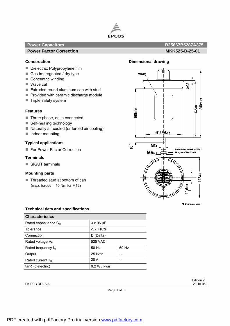
Construction Dimensional drawing
Dielectric: Polypropylene film Gas-impregnated / dry type Concentric winding Wave cut Extruded round aluminum can with stud Provided with ceramic discharge module Triple safety system
FeaturesThree phase, delta connected Self-healing technology Naturally air cooled (or forced air cooling) Indoor mounting
Typical applications For Power Factor Correction
TerminalsSIGUT terminals
Mounting parts Threaded stud at bottom of can
(max. torque = 10 Nm for M12)
Technical data and specifications
Characteristics Rated capacitance CR 3 x 96 µF
Tolerance -5 / +10%
Connection D (Delta)
Rated voltage VR 525 VAC
Rated frequency fR 50 Hz 60 Hz
Output 25 kvar --
Rated current IR 28 A --
tan (dielectric) 0.2 W / kvar
PDF created with pdfFactory Pro trial version www.pdffactory.com

Power Capacitors B25667B5287A375 Power Factor Correction MKK525-D-25-01
Edition 2. FK PFC RD / VA 20.10.05
Page 2 of 3
Maximum ratings Umax (up to 8 h daily) 580 VAC
Umax (up to 1 min) 680 VAC
Imax 1.3 x IR (A)
IS 200 x IR (A)
Test data UTT 1,150 VAC / 50 Hz during 10 s
UTC 3,000 VAC / 50 Hz during 10 s
tan (50 Hz) 0.5 W / kvar
Climatic category / -40/D Tmin (-) 40 ºC
Tmax (+) 55 ºC
Humidity av. rel. < 95%
Maximum altitude 4,000 m Mean life expectancy tLD Up to 115,000 hours
Max. 5000 switchings per year acc. to IEC 60831 Design data Dimensions ( x l) 142 x 200 mm
Weight approx 2.3 kg
Impregnation Dry, inert gas
Fixing Threaded bolt M12
Max. torque (Al can stud) 10 Nm
Mounting position Any mounting position possible. See �Maintenance and Installation Manual� for further details.
Label design
PDF created with pdfFactory Pro trial version www.pdffactory.com

Power Capacitors B25667B5287A375 Power Factor Correction MKK525-D-25-01
Edition 2. FK PFC RD / VA 20.10.05
Page 3 of 3
Please read information about PFC capacitors and cautions as well as installation and maintenance instructions (Power Factor Correction Product Profile, actual version, and Installation and Maintenance Instructions for PFC-capacitors, available in the Internet) to ensure optimum performance and prevent products from failing, and in worst case, bursting and fire. Information given in the PFC-product profile and values given in the data sheet reflect typical specifications. You are kindly requested to approve our product specifications or request our approval for your specification before ordering.
EPCOS AG 2005. All Rights reserved. Reproduction, publication and dissemination of this data sheet, enclosures hereto and the information contained therein without EPCOS' prior express consent is prohibited. The information contained in this data sheet describes the type of component and shall not be considered as guaranteed characteristics. Purchase orders are subject to the General Conditions for the Supply of Products and Services of the Electrical and Electronics Industry recommended by the ZVEI (German Electrical and Electronic Manufacturers' Association), unless otherwise agreed.
TerminalsDegree of protection Isolated terminals, IP20
Max. torque 1.2 Nm
Terminal cross section 16 mm2 (5 AWG)
Maximum terminal current 50 A
Creepage distance 12.7 mm
Clearance 9.6 mm
Safety Mechanical safety Overpressure disconnector
Max. short circuit current (AFC: 10 kA)
Discharge resistor time 1 min (75 V)
Reference Standards IEC 60831-1/2, UL 810-5th edition
Certification: cUL file E238746
PDF created with pdfFactory Pro trial version www.pdffactory.com
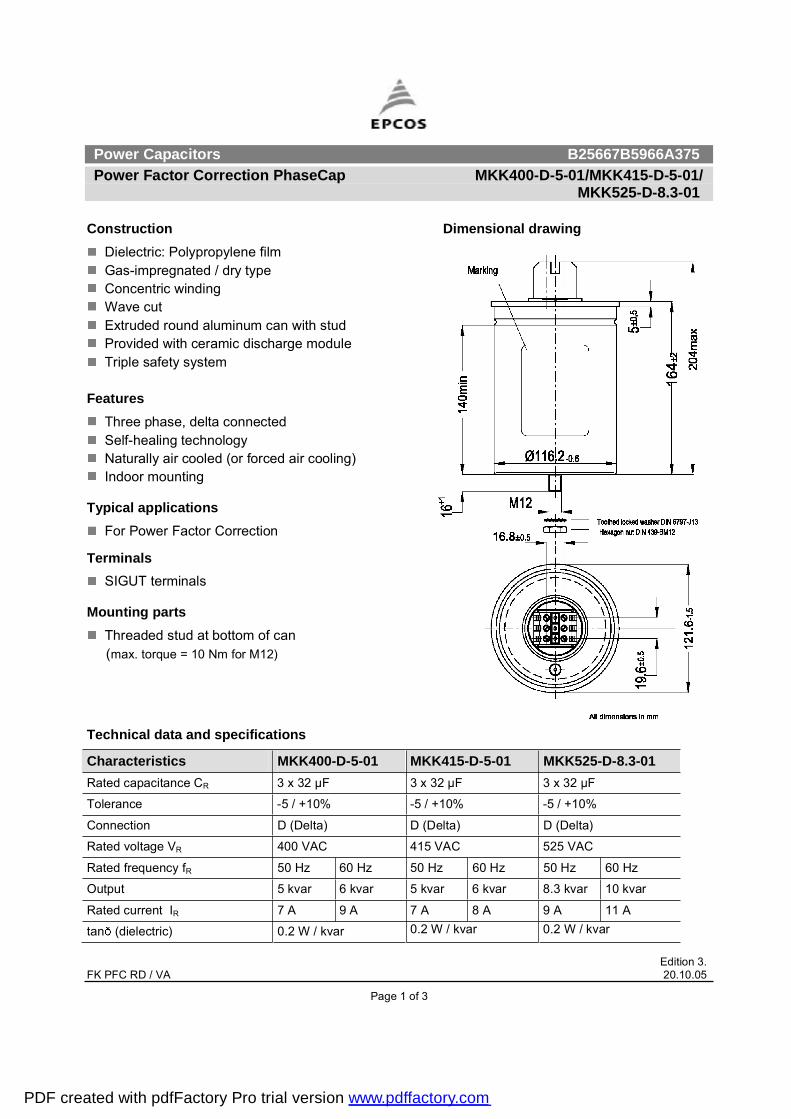
Power Capacitors B25667B5966A375 Power Factor Correction PhaseCap MKK400-D-5-01/MKK415-D-5-01/ MKK525-D-8.3-01
Edition 3. FK PFC RD / VA 20.10.05
Page 1 of 3
Construction Dimensional drawing
Dielectric: Polypropylene film Gas-impregnated / dry type Concentric winding Wave cut Extruded round aluminum can with stud Provided with ceramic discharge module Triple safety system
FeaturesThree phase, delta connected Self-healing technology Naturally air cooled (or forced air cooling) Indoor mounting
Typical applications For Power Factor Correction
TerminalsSIGUT terminals
Mounting parts Threaded stud at bottom of can
(max. torque = 10 Nm for M12)
Technical data and specifications
Characteristics MKK400-D-5-01 MKK415-D-5-01 MKK525-D-8.3-01Rated capacitance CR 3 x 32 µF 3 x 32 µF 3 x 32 µF
Tolerance -5 / +10% -5 / +10% -5 / +10%
Connection D (Delta) D (Delta) D (Delta)
Rated voltage VR 400 VAC 415 VAC 525 VAC
Rated frequency fR 50 Hz 60 Hz 50 Hz 60 Hz 50 Hz 60 Hz
Output 5 kvar 6 kvar 5 kvar 6 kvar 8.3 kvar 10 kvar
Rated current IR 7 A 9 A 7 A 8 A 9 A 11 A
tan (dielectric) 0.2 W / kvar 0.2 W / kvar 0.2 W / kvar
PDF created with pdfFactory Pro trial version www.pdffactory.com
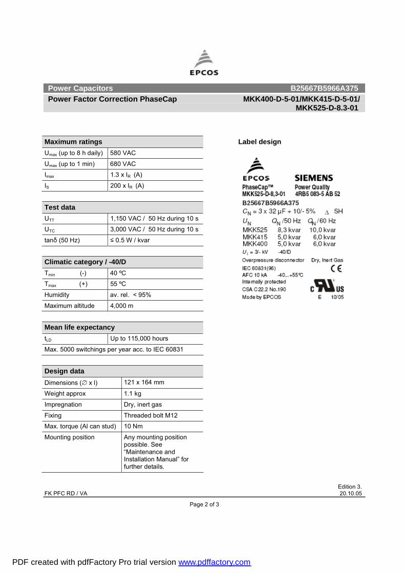
Power Capacitors B25667B5966A375 Power Factor Correction PhaseCap MKK400-D-5-01/MKK415-D-5-01/ MKK525-D-8.3-01
Edition 3. FK PFC RD / VA 20.10.05
Page 2 of 3
Maximum ratings Umax (up to 8 h daily) 580 VAC
Umax (up to 1 min) 680 VAC
Imax 1.3 x IR (A)
IS 200 x IR (A)
Test data UTT 1,150 VAC / 50 Hz during 10 s
UTC 3,000 VAC / 50 Hz during 10 s
tan (50 Hz) 0.5 W / kvar
Climatic category / -40/D Tmin (-) 40 ºC
Tmax (+) 55 ºC
Humidity av. rel. < 95%
Maximum altitude 4,000 m Mean life expectancy tLD Up to 115,000 hours
Max. 5000 switchings per year acc. to IEC 60831 Design data Dimensions ( x l) 121 x 164 mm
Weight approx 1.1 kg
Impregnation Dry, inert gas
Fixing Threaded bolt M12
Max. torque (Al can stud) 10 Nm
Mounting position Any mounting position possible. See �Maintenance and Installation Manual� for further details.
Label design
PDF created with pdfFactory Pro trial version www.pdffactory.com

Power Capacitors B25667B5966A375 Power Factor Correction PhaseCap MKK400-D-5-01/MKK415-D-5-01/ MKK525-D-8.3-01
Edition 3. FK PFC RD / VA 20.10.05
Page 3 of 3
Please read information about PFC capacitors and cautions as well as installation and maintenance instructions (Power Factor Correction Product Profile, actual version, and Installation and Maintenance Instructions for PFC-capacitors, available in the Internet) to ensure optimum performance and prevent products from failing, and in worst case, bursting and fire. Information given in the PFC-product profile and values given in the data sheet reflect typical specifications. You are kindly requested to approve our product specifications or request our approval for your specification before ordering.
EPCOS AG 2005. All Rights reserved. Reproduction, publication and dissemination of this data sheet, enclosures hereto and the information contained therein without EPCOS' prior express consent is prohibited. The information contained in this data sheet describes the type of component and shall not be considered as guaranteed characteristics. Purchase orders are subject to the General Conditions for the Supply of Products and Services of the Electrical and Electronics Industry recommended by the ZVEI (German Electrical and Electronic Manufacturers' Association), unless otherwise agreed.
TerminalsDegree of protection Isolated terminals, IP20
Max. torque 1.2 Nm
Terminal cross section 16 mm2 (5 AWG)
Maximum terminal current 50 A
Creepage distance 12.7 mm
Clearance 9.6 mm
Safety Mechanical safety Overpressure disconnector
Max. short circuit current (AFC: 10 kA)
Discharge resistor time 1 min (75 V)
Reference Standards IEC 60831-1/2, UL 810-5th edition
Certification: cUL file E238746
PDF created with pdfFactory Pro trial version www.pdffactory.com