Embed Size (px)
DESCRIPTION
lab manual to carry out experiment on power electronics
Citation preview

LABORATORY MANUAL
ELE 308
POWER ELECTRONICS
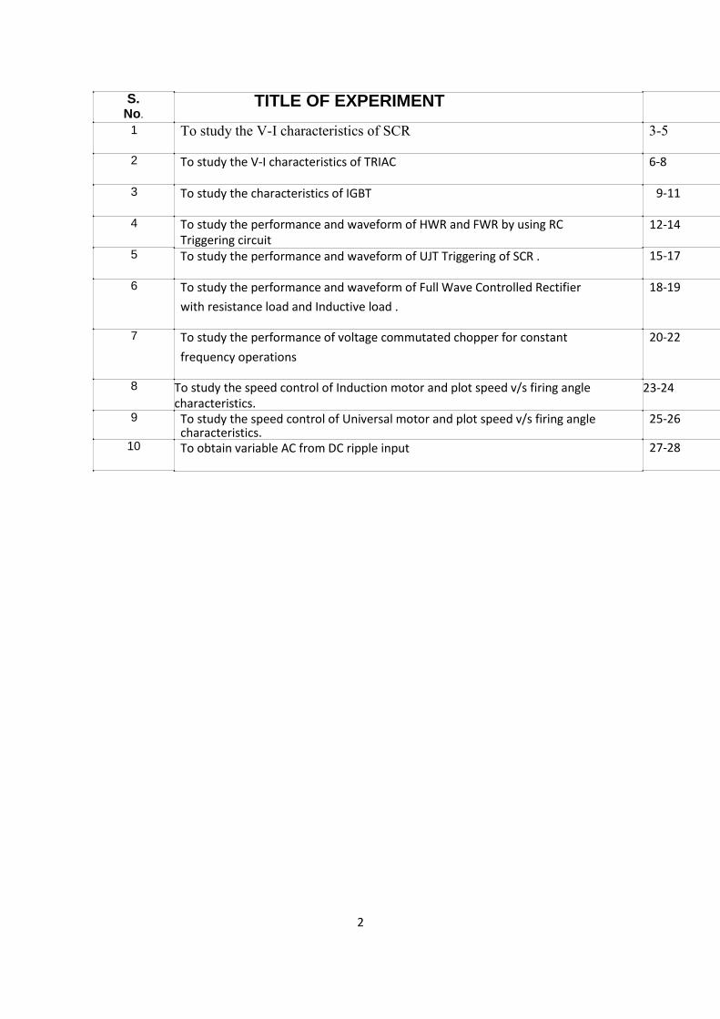
S.
No. 1
2
3
4
5
6
7
8
9
10
TITLE OF EXPERIMENT To study the V-I characteristics of SCR
To study the V-I characteristics of TRIAC
To study the characteristics of IGBT
To study the performance and waveform of HWR and FWR by using RC Triggering circuit To study the performance and waveform of UJT Triggering of SCR .
To study the performance and waveform of Full Wave Controlled Rectifier
with resistance load and Inductive load .
To study the performance of voltage commutated chopper for constant
frequency operations To study the speed control of Induction motor and plot speed v/s firing angle characteristics.
To study the speed control of Universal motor and plot speed v/s firing angle characteristics. To obtain variable AC from DC ripple input
3-5
6-8
9-11
12-14
15-17
18-19
20-22
23-24
25-26
27-28
2

EXPERIMENT 1
To study the V-I characteristics of S.C.R.
Equipment required: - SCR – TY604, Power Supplies, Wattage Resistors, Ammeter, Voltmeter, etc., Learning Object: To practice how to take the values of Latching current and Holding current
Circuit Diagram: -
Ideal Graph: - 3

Outline of the Procedure: -
1. Connections are made as shown in the circuit diagram.
2. The value of gate current IG, is set to convenient value by adjusting VGG.
3. By varying the anode- cathode supply voltage VAA gradually in step-by-
step, note down the corresponding values of VAK & IA. Note down VAK & IA
at the instant of firing of SCR and after firing (by reducing the voltmeter
ranges and in creasing the ammeter ranges) then increase the supply
voltage VAA. Note down corresponding values of VAK & IA.
4. The point at which SCR fires, gives the value of break over voltage VBO.
5. A graph of VAK V/S IA is to be plotted.
6. The on state resistance can be calculated from the graph by using a
formula.
7. The gate supply voltage VGG is to be switched off
8. Observe the ammeter reading by reducing the anode-cathode supply
voltage VAA. The point at which the ammeter reading suddenly goes to
zero gives the value of Holding Current IH.
9. Steps No.2, 3, 4, 5, 6, 7, 8 are repeated for another value of the gate
current IG.
RESULT : -
Volts Amp S. No g
4

Cautions: 1) All connection should be tight. 2) Wire should not over long. 3) After completing the job all tools must be kept at proper place. 4) Keep your mind and eyes on the job & don’t talk any one while working. 5) Tools not being used should not be scatter on working table.
Learning outcomes: to be written by the students in 50-70 words.
5
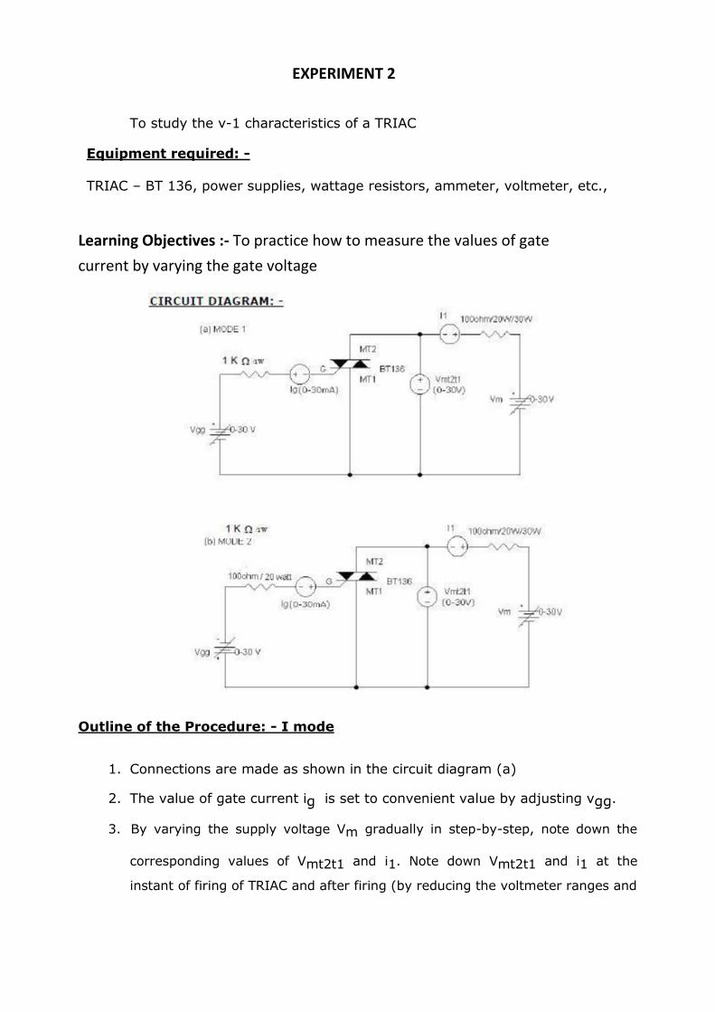
EXPERIMENT 2
To study the v-1 characteristics of a TRIAC Equipment required: -
TRIAC – BT 136, power supplies, wattage resistors, ammeter, voltmeter, etc.,
Learning Objectives :- To practice how to measure the values of gate
current by varying the gate voltage
Outline of the Procedure: - I mode
1. Connections are made as shown in the circuit diagram (a)
2. The value of gate current ig is set to convenient value by adjusting vgg.
3. By varying the supply voltage Vm gradually in step-by-step, note down the
corresponding values of Vmt2t1 and i1. Note down Vmt2t1 and i1 at the
instant of firing of TRIAC and after firing (by reducing the voltmeter ranges and
increasing the ammeter ranges) then increase the supply voltage Vmt2mt1 and
i1.
4. The point at which TRIAC fires gives the value of break over voltage vbo1
5. A graph of vmt2t1 v/s i1 is to be plotted.
6. The gates supply voltage. Vgg is to be switched off
7. Observe the am meter reading by reducing the supply voltage vmt. The
point at which the ammeter reading suddenly goes to zero gives the value
of holding current ih. II mode: -
1. Connections are made as shown in the circuit diagram (b)
2. The gate current is set as same value as in i-mode
3. Repeat the step no. s 3, 4, 5, 6, & 7 of I-mode
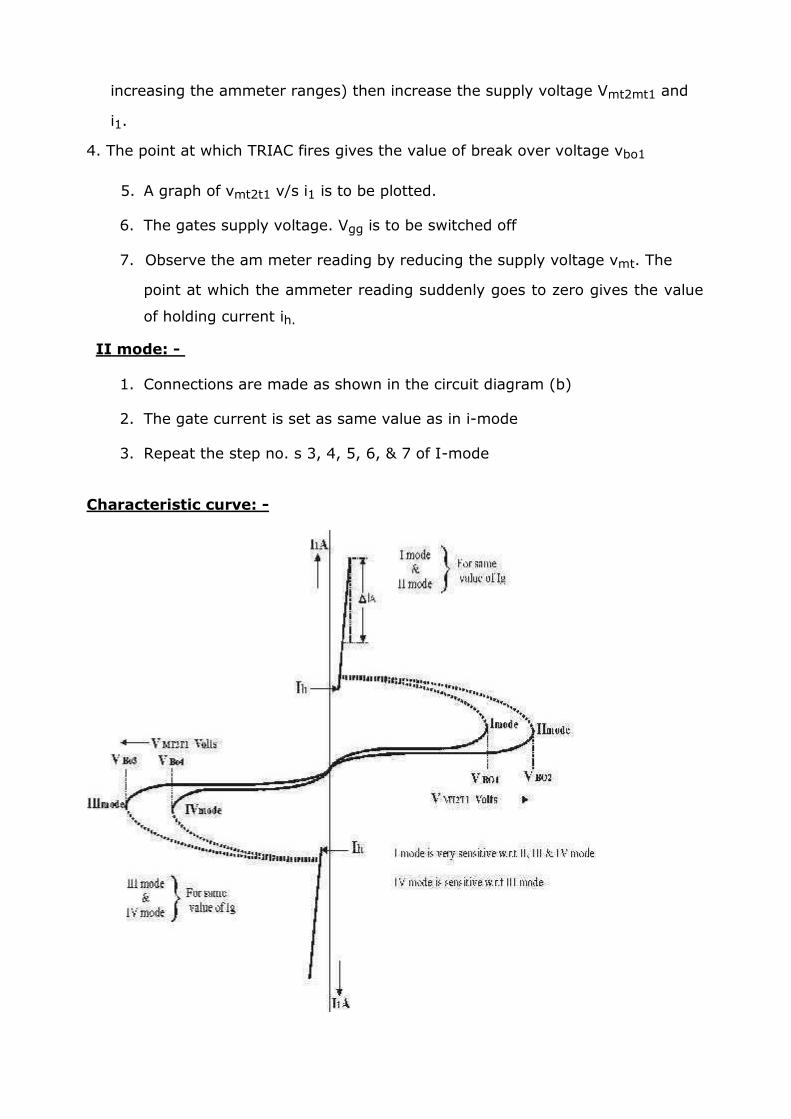
Characteristic curve: -
RESULT: -
I-mode II-mode i g = ma I g = ma
Sl.no VTRIAC volts ITRIAC ma Sl.no VTRIAC volts ITRIAC ma
Cautions:
1) All connection should be tight. 2) Wire should not over long. 3) After completing the job all tools must be kept at proper place. 4) Keep your mind and eyes on the job & don’t talk any one while working. 5) Tools not being used should not be scatter on working table.
Learning outcomes: to be written by the students in 50-70 words.
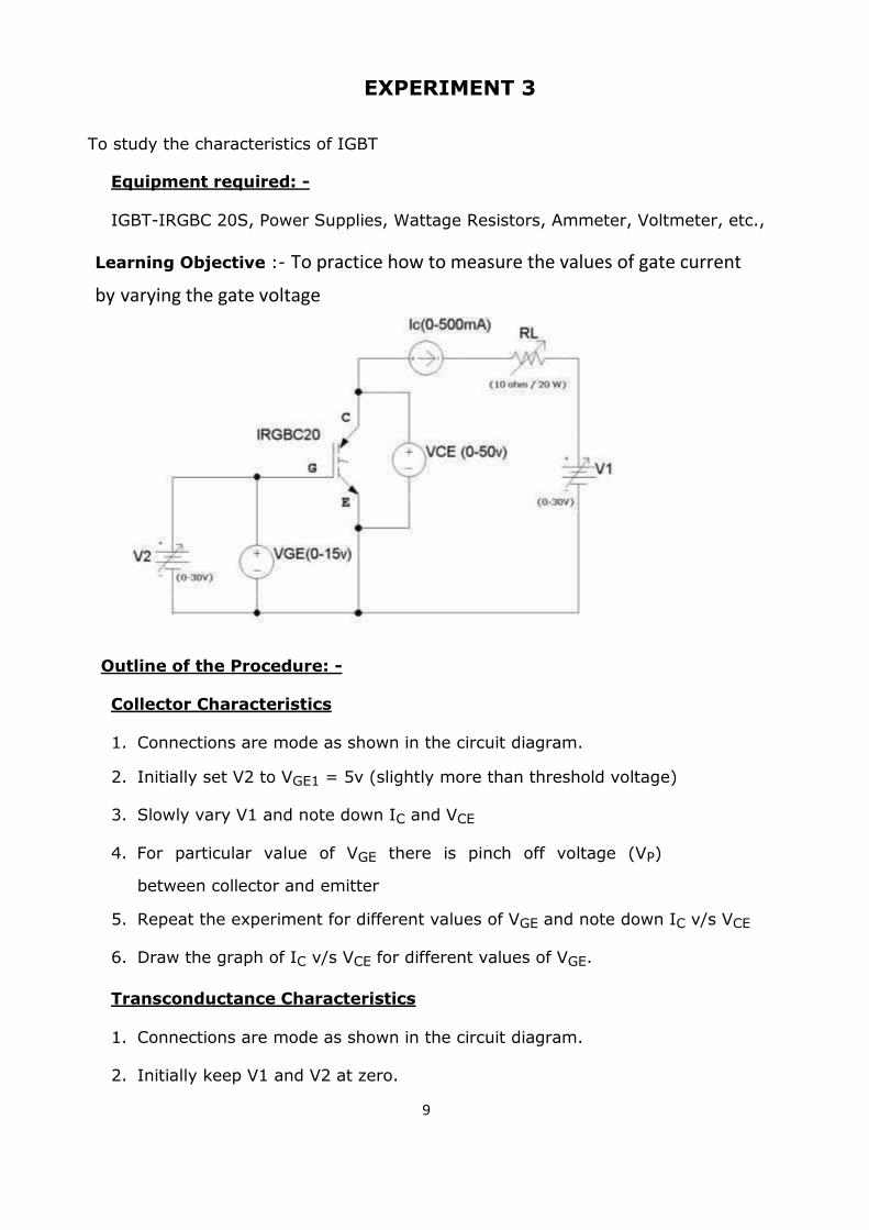
EXPERIMENT 3
To study the characteristics of IGBT
Equipment required: -
IGBT-IRGBC 20S, Power Supplies, Wattage Resistors, Ammeter, Voltmeter, etc.,
Learning Objective :- To practice how to measure the values of gate current
by varying the gate voltage
Outline of the Procedure: -
Collector Characteristics
1. Connections are mode as shown in the circuit diagram.
2. Initially set V2 to VGE1 = 5v (slightly more than threshold voltage)
3. Slowly vary V1 and note down IC and VCE
4. For particular value of VGE there is pinch off voltage (VP)
between collector and emitter
5. Repeat the experiment for different values of VGE and note down IC v/s VCE
6. Draw the graph of IC v/s VCE for different values of VGE.
Transconductance Characteristics
1. Connections are mode as shown in the circuit diagram.
2. Initially keep V1 and V2 at zero. 9
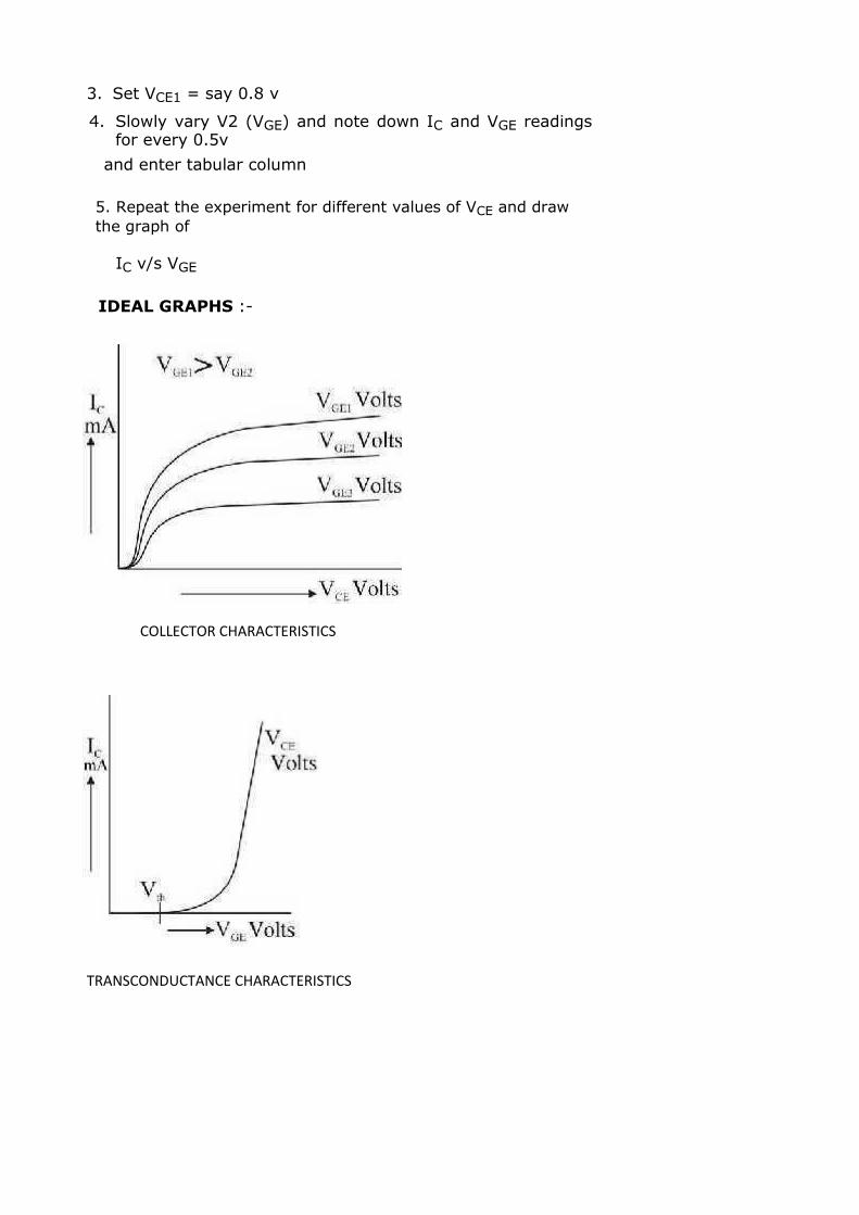
3. Set VCE1 = say 0.8 v
4. Slowly vary V2 (VGE) and note down IC and VGE readings for every 0.5v
and enter tabular column
5. Repeat the experiment for different values of VCE and draw
the graph of
IC v/s VGE
IDEAL GRAPHS :-
COLLECTOR CHARACTERISTICS
TRANSCONDUCTANCE CHARACTERISTICS

RESULT :-
VGE =
VCE(V) IC(mA) Cautions :
1) All connection should be tight. 2) Wire should not over long. 3) After completing the job all tools must be kept at proper place. 4) Keep your mind and eyes on the job & don’t talk any one while working. 5) Tools not being used should not be scatter on working table
Learning outcomes: to be written by the students in 50-70 words.
11
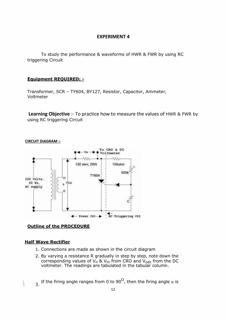
EXPERIMENT 4
To study the performance & waveforms of HWR & FWR by using RC
triggering Circuit
Equipment REQUIRED: -
Transformer, SCR – TY604, BY127, Resistor, Capacitor, Ammeter, Voltmeter
Learning Objective :- To practice how to measure the values of HWR & FWR by using RC triggering Circuit
CIRCUIT DIAGRAM :-
Outline of the PROCEDURE
Half Wave Rectifier
1. Connections are made as shown in the circuit diagram
2. By varying a resistance R gradually in step by step, note down the
corresponding values of Vn & Vm from CRO and Vodc from the DC
⎞
voltmeter. The readings are tabulated in the tabular column.
3. If the firing angle ranges from 0 to 90
O, then the firing angle α is
12

4. The conduction angle R Watts respectively
5.
β α
.
A graph of Vo v/s α , Vo v/s , Io v/s
α , Io v/s , Podc v/s
α , Podc v/s
β are
6. to be plotted. β β
7. Compare practical output voltage with theoretical output voltage,
V
oth =
Vm
whereVm=
2π (1+cosα)volts 2V
rms
Full Wave Rectifier
1.Repeat the above said procedure for full wave rectifier. WAVEFORMS :-
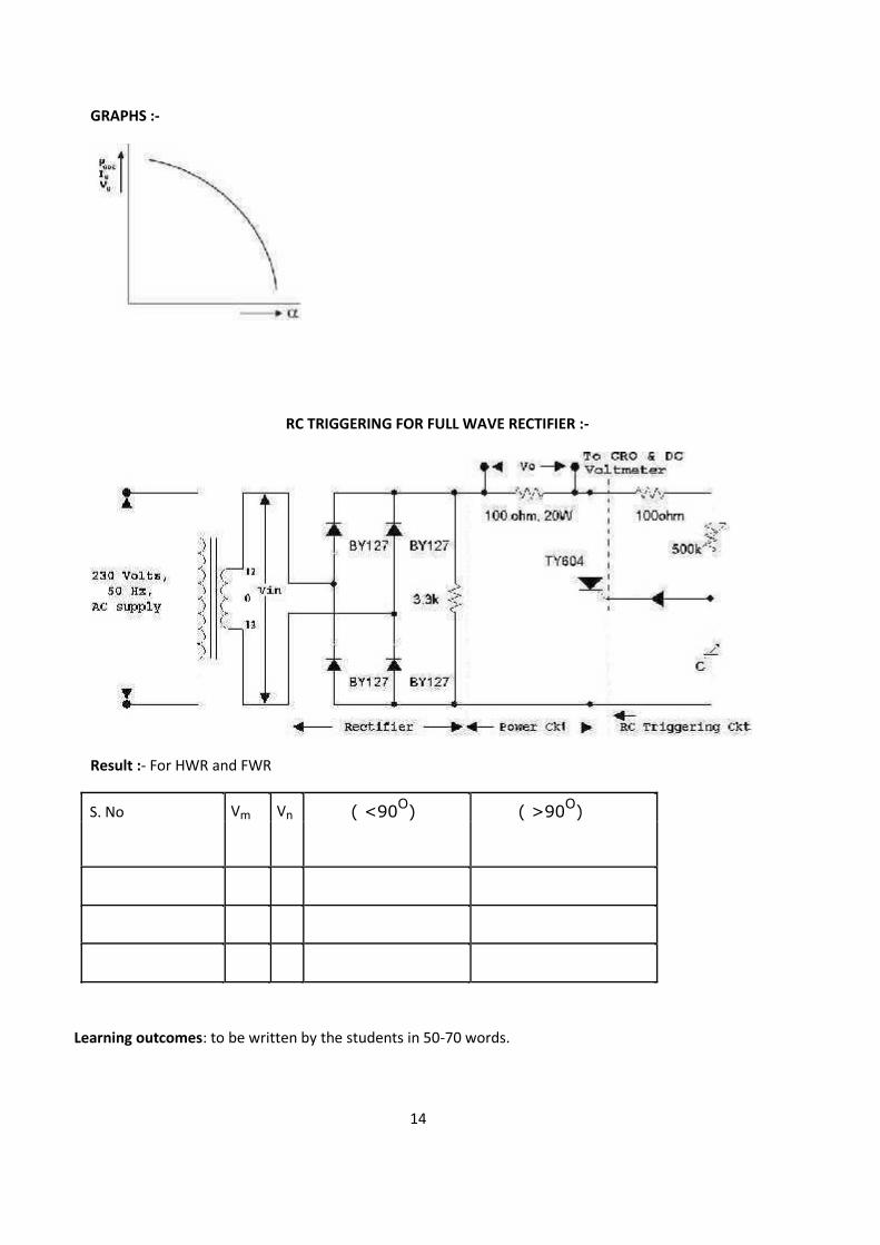
GRAPHS :-
RC TRIGGERING FOR FULL WAVE RECTIFIER :-
Result :- For HWR and FWR
S. No Vm Vn ( <90O) ( >90
O)
Learning outcomes: to be written by the students in 50-70 words.
14
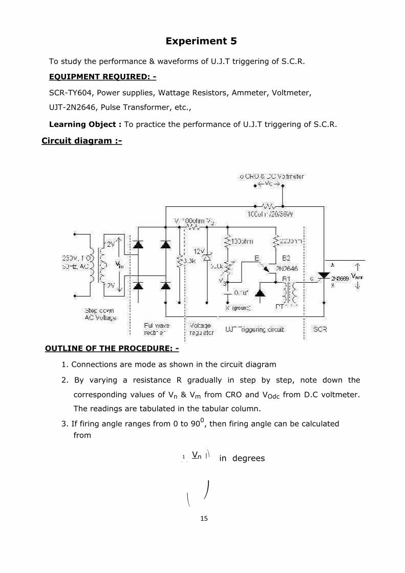
Experiment 5
To study the performance & waveforms of U.J.T triggering of S.C.R.
EQUIPMENT REQUIRED: -
SCR-TY604, Power supplies, Wattage Resistors, Ammeter, Voltmeter,
UJT-2N2646, Pulse Transformer, etc.,
Learning Object : To practice the performance of U.J.T triggering of S.C.R.
Circuit diagram :- OUTLINE OF THE PROCEDURE: -
1. Connections are mode as shown in the circuit diagram
2. By varying a resistance R gradually in step by step, note down the
corresponding values of Vn & Vm from CRO and VOdc from D.C voltmeter.
The readings are tabulated in the tabular column.
3. If firing angle ranges from 0 to 900, then firing angle can be calculated
from
1 Vn ⎟⎞ in degrees
α = Sin− ⎜⎛ Vm
⎝ ⎠
15
If firing angle ranges from 900 to 180
0, then firing
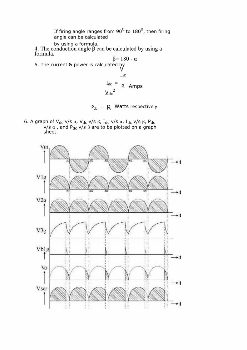
angle can be calculated by using a formula,
4. The conduction angle β can be calculated by using a formula,
β= 180 - α 5. The current & power is calculated by
Idc =
Vdc
Amps
Pdc =
R
Vdc2
R Watts respectively
6. A graph of Vdc v/s α, Vdc v/s β, Idc v/s α, Idc v/s β, Pdc
v/s α , and Pdc v/s β are to be plotted on a graph sheet.
7. For given frequency, the value of R can be calculated by using a formula,
T = 2.303RC.log10
1
1 − η
T
R=
Ω
2.303C.log10 1 −1η
When C = 0.1 mF & N = Intrinsic stand off ratio = 0.67
8. This value of R is set in the circuit, Step No S 3. 4. 5. &
6. are repeated and waveforms are observed at
different points as shown.
Cautions: 1) All connection should be tight. 2) Wire should not over long. 3) After completing the job all tools must be kept at proper place. 4) Keep your mind and eyes on the job & don’t talk any one while working. 5) Tools not being used should not be scatter on working table.
Learning outcomes: to be written by the students in 50-70 words.

EXPERIMENT 6
To study the performance and waveforms of full wave controlled rectifier
with Resistance load and Inductive load EQUIPMENT REQUIRED: -
SCR-TY604, Power supplies, Wattage Resistors, Ammeter, Voltmeter,
UJT-2N2646, BY127, Inductor, Pulse Transformer, etc.,
Learning Object : To practice the performance of full wave controlled rectifier
CIRCUIT DIAGRAM :- With R Load (resistive Load)
OUTLINE OF THE PROCEDURE: -
1. Connections are made as shown in the circuit diagram for resistive load.
2. By varying a variable resistor R in step-by-step gradually. Note down
corresponding values of VN, VM, from C.R.O. and VO or Vload or VDC from
d.c.voltmeter for resistive load, the readings are tabulated in the tabular
column 3. If α varies from 0 To 900, then firing angle can be calculated from
angle to angle 4. For Inductance load repeat step no.
1,2,3&4
Cautions: 1) All connection should be tight. 2) Wire should not over long. 3) After completing the job all tools must be kept at proper place. 4) Keep your mind and eyes on the job & don’t talk any one while working. 5) Tools not being used should not be scatter on working table.
Learning outcomes: to be written by the students in 50-70 words. 19
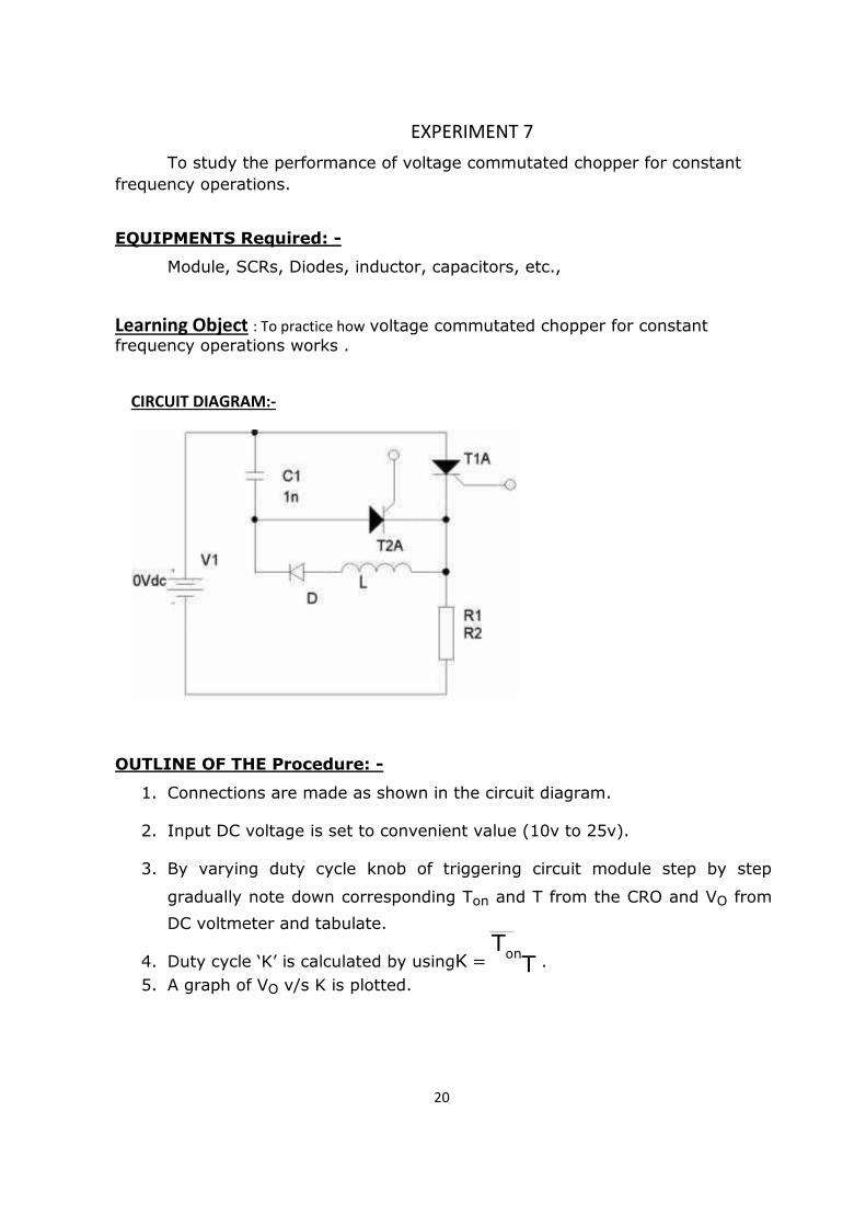
EXPERIMENT 7
To study the performance of voltage commutated chopper for constant
frequency operations. EQUIPMENTS Required: -
Module, SCRs, Diodes, inductor, capacitors, etc.,
Learning Object : To practice how voltage commutated chopper for constant frequency operations works .
CIRCUIT DIAGRAM:-
OUTLINE OF THE Procedure: -
1. Connections are made as shown in the circuit diagram.
2. Input DC voltage is set to convenient value (10v to 25v).
3. By varying duty cycle knob of triggering circuit module step by step
gradually note down corresponding Ton and T from the CRO and VO from
DC voltmeter and tabulate.
4. Duty cycle ‘K’ is calculated by usingK = T
onT .
5. A graph of VO v/s K is plotted. 20
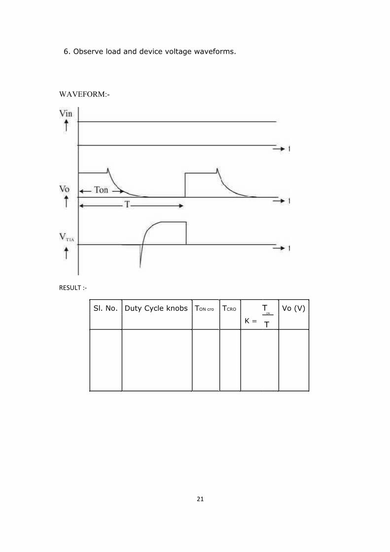
6. Observe load and device voltage waveforms. WAVEFORM:- RESULT :-
Sl. No. Duty Cycle knobs TON cro TCRO
K =
T Vo (V)
ON
T
21

Cautions:
1) All connection should be tight. 2) Wire should not over long. 3) After completing the job all tools must be kept at proper place. 4) Keep your mind and eyes on the job & don’t talk any one while working. 5) Tools not being used should not be scatter on working table.
Learning outcomes: to be written by the students in 50-70 words. 22
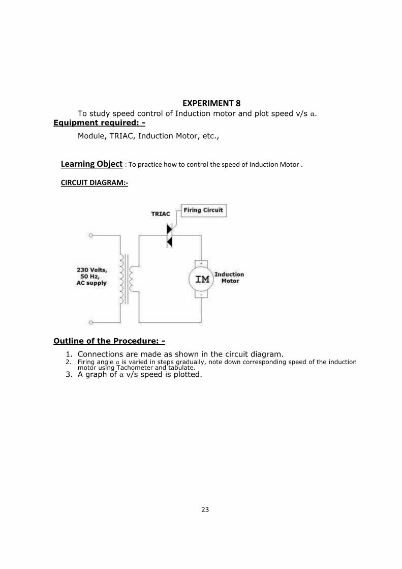
To study speed control of Induction motor and plot speed v/s α. Equipment required: -
Module, TRIAC, Induction Motor, etc.,
Learning Object : To practice how to control the speed of Induction Motor .
CIRCUIT DIAGRAM:-
Outline of the Procedure: -
1. Connections are made as shown in the circuit diagram. 2. Firing angle α is varied in steps gradually, note down corresponding speed of the induction
motor using Tachometer and tabulate. 3. A graph of α v/s speed is plotted.
23
EXPERIMENT 8
RESULT :-
Sl. No. Firing Angle ( ) Speed in RPM
Cautions:
1) All connection should be tight. 2) Wire should not over long. 3) After completing the job all tools must be kept at proper place. 4) Keep your mind and eyes on the job & don’t talk any one while working. 5) Tools not being used should not be scatter on working table.
Learning outcomes: to be written by the students in 50-70 words.
24

To study speed control of Universal motor and plot speed v/s α. Equipment required: -
Module, TRIAC-BT136, Universal Motor, Diode-IN4001 etc.,
Learning Object : To practice how to control the speed
CIRCUIT DIAGRAM:-
Universal Motor (DC)
Universal Motor (AC)
25
EXPERIMENT 9
Outline of the Procedure: -
DC Motor: -
1. Connections are made as shown in the circuit diagram. 2. Firing angle α is varied in steps gradually, note down corresponding speed of the induction
motor using Tachometer and tabulate. 3. A graph of α v/s speed is plotted.
AC Motor: -
1. Above procedure is repeated for AC Motor.
Result :- For AC & DC Motor
S.NO. Firing Angle Speed in RPM
Cautions:
1) All connection should be tight. 2) Wire should not over long. 3) After completing the job all tools must be kept at proper place. 4) Keep your mind and eyes on the job & don’t talk any one while working. 5) Tools not being used should not be scatter on working table.
Learning outcomes: to be written by the students in 50-70 words. 26

EXPERIMENT 10
To obtain variable AC from DC ripple input.
Equipmentrequired: -
Module, SCRs, Diodes, inductor, capacitors, etc., Learning Object : To practice the connections of series Inverter
CIRCUIT DIAGRAM :-
Outline of the Procedure: -
1. To begin with switch on the power supply to the firing circuit check that
trigger pulses by varying the frequency.
2. Connections are made as shown in the circuit diagram.
3. Now connect trigger outputs from the firing circuits to gate and cathode
of SCRs T1 & T2.
4. Connect DC input from a 30v/2A regulated power supply and switch on
the input DC supply.
5. Now apply trigger pulses to SCRs and observe voltage waveform across

the load. 27

6. Measure Vorms & frequency of o/p voltage waveform.
Waveforms :-
Cautions:
1) All connection should be tight. 2) Wire should not over long. 3) After completing the job all tools must be kept at proper place. 4) Keep your mind and eyes on the job & don’t talk any one while working. 5) Tools not being used should not be scatter on working table.
Learning outcomes: to be written by the students in 50-70 words. 28


![[VTUWORLD]7th Sem Power Electronics Lab Manual](https://img.pdfslide.net/doc/110x75/552dec1c4a7959485c8b481a/vtuworld7th-sem-power-electronics-lab-manual.jpg)