Embed Size (px)
Citation preview
IME Proprietary
Page 1
Power Electronics Packaging Solutions for Device Junction
Temperature over 220oC
EPRC – 12 Project Proposal
15th August 2012

IME Proprietary
Page 2
2
Motivation
Electronic Vehicle
Source: Toyota
Source: Yole
Source: Infineon
Renewable energy
Aerospace
Hybrid Vehicle
Source: Nissan
Electronic Railway
• Increased requirements of high power semiconductor device module for future automotive, aerospace and green & renewable energy industry
• Emerging wide band gap power devices : SiC and GaN can be operated >220oC

IME Proprietary
Page 3
3
Technology Trends• Technology trends for high power module and discrete :
High temperature endurable materials >220oC (silver sintering, encapsulations) High reliable and low stress interconnections (foil interconnects, ultrasonic bonding) Thermal cooling solution (Dual-side cooling / micro-channel cooling )
Source: Yole

IME Proprietary
Page 4
4
Challenges to be Addressed
Power Module
Base plate
PassiveDBC substrate
Encapsulation Materials Plastic case• Thermal endurance >220C• Void free processing• Lower stress (CTE, Modulus) • High power insulation• Moisture barrier • Delamination free
• Thermal endurance >220C• Void free processing• Lower stress (CTE, Modulus) • Electrical conductive• Die backside metallization
Power Device Attach
IGBTDiode
Encapsulations
Power Source Interconnection • Power cycling endurance• Temp cycle endurance • Process optimization• inter-metallic diffusion• Thermal & Electrical properties
Substrate (DBC) • Temp cycling endurance• Adhesion with Encapsulation• Adhesion between Cu/Ceramic• Surface finish • Thermal & Electrical properties
Passive component attach• Thermal endurance >220C• Void free processing• Temp cycle endurance • Electrical conductive• Metallization > 220C
IGBT
Power Discrete
Heat spreader
Wire
WireThermal interface materials• Thermal endurance > 220C • Temp cycle endurance • Delamination & fracture • Thermal conductivity
Base plate (system board)
Reliability testing methodologies• Reliability test spec• Reliability testing method• Failure Analysis / reliability model
Modeling and predictions• Thermal characterization• Mechanical characterization• Electro-thermal-mechanical coupling• Reliability model (power cycling)
Lead frame
IME Proprietary
Page 5
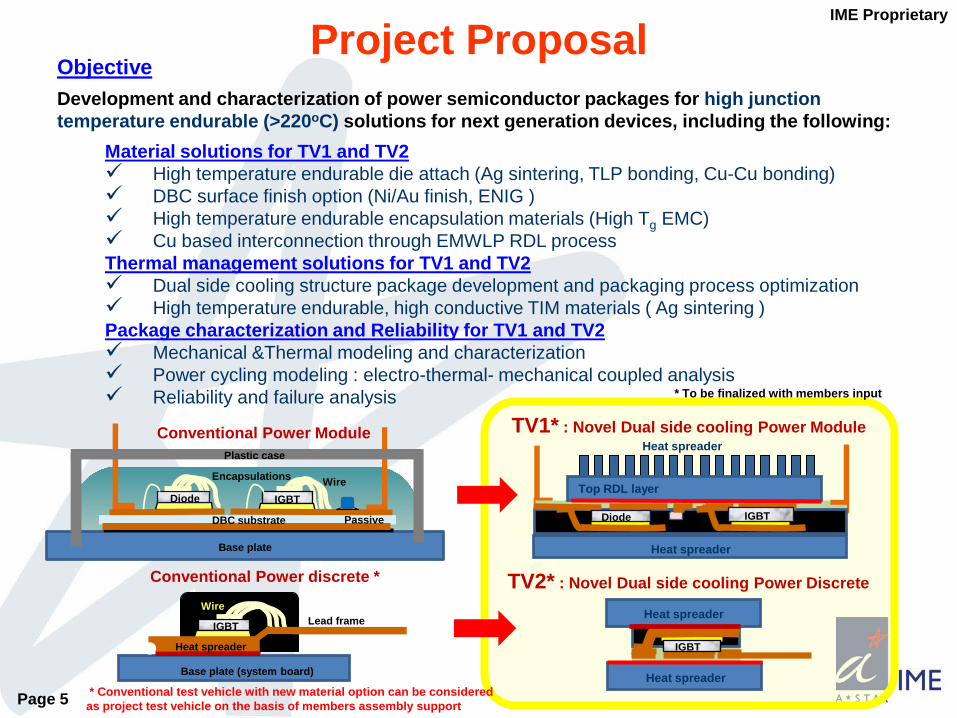
Objective Development and characterization of power semiconductor packages for high junction temperature endurable (>220oC) solutions for next generation devices, including the following:
Material solutions for TV1 and TV2 High temperature endurable die attach (Ag sintering, TLP bonding, Cu-Cu bonding) DBC surface finish option (Ni/Au finish, ENIG ) High temperature endurable encapsulation materials (High Tg EMC) Cu based interconnection through EMWLP RDL processThermal management solutions for TV1 and TV2 Dual side cooling structure package development and packaging process optimization High temperature endurable, high conductive TIM materials ( Ag sintering )Package characterization and Reliability for TV1 and TV2 Mechanical &Thermal modeling and characterization Power cycling modeling : electro-thermal- mechanical coupled analysis Reliability and failure analysis
Project Proposal
Conventional Power Module
Base plate
PassiveDBC substrate
Plastic case
IGBTDiode
Encapsulations Wire
IGBT
Wire
Base plate (system board)
Lead frame
Conventional Power discrete *
Heat spreader
Heat spreader
Diode IGBT
TV1* : Novel Dual side cooling Power Module
Top RDL layer
Heat spreader IGBT
TV2* : Novel Dual side cooling Power Discrete
Heat spreader
Heat spreader
* To be finalized with members input
* Conventional test vehicle with new material option can be considered as project test vehicle on the basis of members assembly support

IME Proprietary
Page 6
Structural modeling and interconnection life prediction for novel dual side cooling power module Power source/gate/drain RDL design
optimization for stress minimization Interconnection fatigue life prediction (plastic
constitutive model for Cu RDL) Packaging material properties effect on the
investigation Electro-thermo-mechanical coupled power
cycling impact modeling Ref. Hua Lua et al. “Lifetime Prediction for Power Electronics Module Substrate Mount-down Solder Interconnect” Proceedings of HDP’07
Thermal modeling and characterization Thermal resistance modeling for selected
material set and design Experimental Thermal resistance
Rthjc characterization Liquid based active cooling investigation
Ref. Institute of MicroelectronicsDual side cooling effect Tjmax decreased compared with single side cooling
Design Optimization and Reliability Prediction for Power Module/Discrete with Dual Side Cooling
IME Proprietary
Page 7
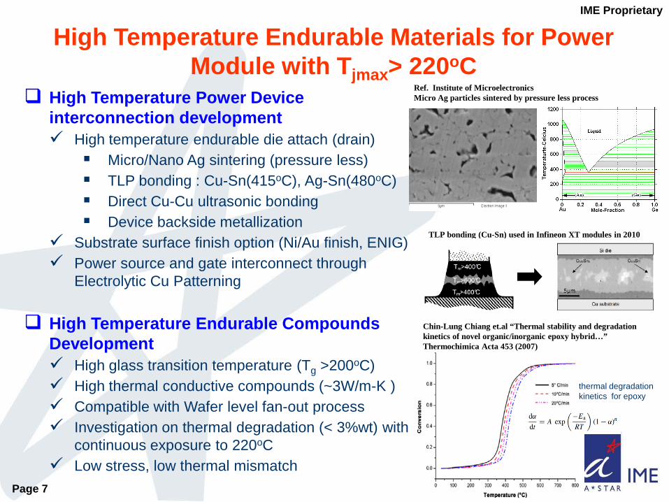
High Temperature Power Device interconnection development High temperature endurable die attach (drain)
Micro/Nano Ag sintering (pressure less) TLP bonding : Cu-Sn(415oC), Ag-Sn(480oC) Direct Cu-Cu ultrasonic bonding Device backside metallization
Substrate surface finish option (Ni/Au finish, ENIG) Power source and gate interconnect through
Electrolytic Cu Patterning
High Temperature Endurable Compounds Development High glass transition temperature (Tg >200oC) High thermal conductive compounds (~3W/m-K ) Compatible with Wafer level fan-out process Investigation on thermal degradation (< 3%wt) with
continuous exposure to 220oC Low stress, low thermal mismatch
High Temperature Endurable Materials for Power Module with Tjmax> 220oC
TLP bonding (Cu-Sn) used in Infineon XT modules in 2010
Ref. Institute of MicroelectronicsMicro Ag particles sintered by pressure less process
Chin-Lung Chiang et.al “Thermal stability and degradation kinetics of novel organic/inorganic epoxy hybrid…” Thermochimica Acta 453 (2007)
thermal degradation kinetics for epoxy

IME Proprietary
Page 8
Thermal Interface Material investigation High conductive /temperature endurable Metallic TIM (Ag sintering) with high power insulation
layer (Al2O3) Polymeric TIM with conductivity > 4W/m-K Thickness control Thermal performance consistency investigation after
reliability test
High Temperature Endurable Dielectric passivation layer High glass transition temperature (Tg >200oC) BCB, Polyimide photo sensitive PR Compatible with Wafer level fan-out process Investigation on thermal degradation (< 3%wt) with
continuous exposure to 220oC Low stress, low thermal mismatch
High Temperature Endurable Materials for Power Module with Tjmax> 220oC
Source : Danfoss
Source : Danfoss
Ag sintering for TIM
TIM layer crack propagation

IME Proprietary
Page 9
Dual side Cooling Power Module Assembly Process development Cu clip (Ag plated) attachment / alignment Evaluation of molding material Liquid, Granular Process condition (Temperature, time, pressure) Module shift analysis & control Die/ module pick & place tolerance Minimum clearance between die Warpage control Heat spreader attach and TIM process
Reliability Assessments for High Power Application Temperature cycling (Test condition : TBD*1) High Temperature Storage ( 220oC/ 1000 hrs ) HAST (non-biased) Power Cycling test (optional*2) Failure analysis
Dual Side Cooling Power Module Process Optimization and Reliability Assessment
IME’s Novel Dual side Cooling Power Module Assembly Process
*1 To be finalized with members input*2 Need member’s support on actual SiC wafer and testing
Power cycling : IGBT with 300W,10Hz
Tilo Poller et al. “Influence of thermal cross-couplings on power cycling lifetime of IGBT power modules” CIPS 2102

IME Proprietary
Page 10
Thermal and Structural optimization and life prediction for novel dual side cooling power module Interconnection fatigue life prediction (plastic constitutive model for Cu RDL) Packaging material properties effect on the test vehicle Thermal modeling characterization for selected material set and test vehicles Electro-thermo-mechanical coupled power cycling impact analysis
Tjmax >220oC : High Temperature Endurable Power Device Packaging material Solutions (interconnect/encapsulation/TIM) High temperature endurable die attach material characterization using Micro/Nano
Ag sintering, TLP bonding, Direct Cu-Cu ultrasonic bonding Power source and gate interconnect through Electrolytic Cu Patterning Wafer level Fan-out compatible compounds characterization TIM process optimization for dual side application
Dual side Cooling Power Module Assembly Process development Copper clip (Ag plated) attachment / alignment Mold Process condition optimization (Temperature, time, pressure) Heat spreader attach and TIM process
Reliability Assessments & F/A for Novel High Power Module Temperature cycling High Temperature Storage / Low Temperature Storage HAST (non-biased) Power Cycling test (optional) Failure analysis
Possible Research Outcome*
* To be finalized
IME Proprietary
Page 11
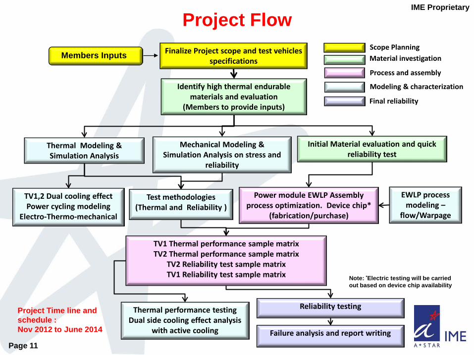
Project FlowFinalize Project scope and test vehicles
specifications
Mechanical Modeling & Simulation Analysis on stress and
reliability
Initial Material evaluation and quick reliability test
Thermal performance testingDual side cooling effect analysis
with active cooling
Reliability testing
Failure analysis and report writing
Identify high thermal endurable materials and evaluation
(Members to provide inputs)
Thermal Modeling & Simulation Analysis
Test methodologies (Thermal and Reliability )
Members Inputs
EWLP process modeling –
flow/Warpage
TV1,2 Dual cooling effectPower cycling modeling
Electro-Thermo-mechanical
Power module EWLP Assembly process optimization. Device chip*
(fabrication/purchase)
TV1 Thermal performance sample matrixTV2 Thermal performance sample matrix
TV2 Reliability test sample matrix TV1 Reliability test sample matrix
Scope PlanningMaterial investigation
Process and assembly
Modeling & characterization
Final reliability
Project Time line andschedule : Nov 2012 to June 2014
Note: *Electric testing will be carried out based on device chip availability

IME Proprietary
Page 12