Embed Size (px)
Citation preview

NREL is a national laboratory of the U.S. Department of Energy Office of Energy Efficiency and Renewable Energy operated by the Alliance for Sustainable Energy, LLC
Power Electronics Thermal ControlSreekant NarumanchiCenter for Transportation Technologies and Systems
Presented at theInteragency Advanced Power Group Meeting
Golden, Colorado May 5, 2010
NREL/PR-540-48053
NREL’s Center for Transportation Technologies and Systems
National Renewable Energy Laboratory Innovation for Our Energy Future2
Energy Storage Thermal Control
Biofuels and Engine Optimization
Powertrain Engine Tradeoffs(Perf., Size, Cost, Life)
DIRECT
Vehicle Thermal and EnergyManagement Strategies
Real WorldDrive Cycle Analysis
Thermal Impacts onTailpipe Emissions
Cabin Thermal Comfortand Waste Heat Utilization
WinDsHOMER
Utility Interface/Renewable Energy
Power Electronics Thermal Control

DOE’s Advanced Power Electronics and Electric Machines (APEEM)
National Renewable Energy Laboratory Innovation for Our Energy Future3
Industry and Academia
Oak Ridge National Laboratory (ORNL)Lead: Power Electronics & Electric Machines R&D
National Renewable Energy Laboratory (NREL)Lead: APEEM Thermal Control R&D
+Other Industry Partnersand Universities

DOE’s Advanced Power Electronics and Electric Machines (APEEM)
National Renewable Energy Laboratory Innovation for Our Energy Future4
Research Focus Areas
Power Electronics
($/kW) (kW/kg) (kW/l)
7.9 10.8 8.7
5 12 12
3.3 14.1 13.4
Motors
($/kW) (kW/kg) (kW/l)
11.1 1.2 3.7
7 1.3 5
4.7 1.6 5.7
Traction Drive System
($/kW) (kW/kg) (kW/l) Efficiency
19 1.06 2.6 >90%
12 1.2 3.5 >93%
8 1.4 4 >94%
Power Electronics
Integrated Traction Drive
System
PEEM Thermal ControlMotors
inverters and converters innovative topologies packaging temperature-tolerant devices capacitors
permanent magnet (PM) motors high performance non-PM motors permanent magnets
heat transfer techniques materials area enhancement alternative coolants
benchmarking technologies innovative system designs
Challengessize cost weight
Year
2010
2015
2020
Reduce Dependence on OilVia Electrification of Vehicle Drives
Technology Targets
Requirements: 55 kW peak for 18 sec; 30 kW continuous; 15-year life; coolant (air or 105oC WEG)

5
Technical targetsCoolant System
Material SelectionNumber of Devices
Heat Generation
Cooling Requirements
Heat Exchanger Materials
Heat Flux
Heat ExchangerVolume
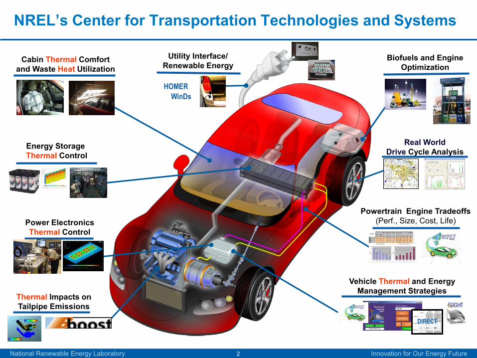
FY10 – Thermal Management projects
PE P
acka
ging
Ther
mal
Sys
tem
s In
tegr
atio
n
Hea
t Tra
nsfe
r Te
chno
logi
es
Ther
mal
Stre
ss a
nd
Rel
iabi
lity
Thermal System Performance and IntegrationElectical and Thermal Characterization, Modeling, and Reliability Assessment
Thermal Stress and Reliability
Thermal performance and reliability of bonded interfacesCharacterization and Development of Advanced Heat Transfer Technologies
Air Cooling Technology
Thermal Control of PHEV / EV Charging Systems
Electric Motor Thermal Control
Thermal Assessment
PROJECT
FOCUSAREA

Approach
National Renewable Energy Laboratory Innovation for Our Energy Future7
)( CB TTAhQ −=
Improve PE device efficiency (ORNL)
Enhance heat transfer coefficient- jet / spray cooling- self-oscillating jets- phase change
Coolant temperature- reduce coolant temperature- evaluate alternatives
Increase surface area- fin shape optimization- double sided cooling- surface enhancements- thermal spreading
Maximize base plate temperature- PE materials selection- reduce thermal resistance
Integration and Reliability
National Renewable Energy Laboratory Innovation for Our Energy Future8
Enhanced surfaces in conjunction with single-phase and two-phase flows

ApproachSurface enhancement: Single-phase channel flow, jet impingement
• Further increase the heat transfer rates in conjunction with single-phase channel flows and jet impingement.
• Prior studies have shown that surface roughening can:
• Increase h-values by as much as 32% [Gabour & Lienhard (1994)],
• Reduce Rth by as much as 60% [Sullivan et al. (1992)].
• Limited, if any, studies exist on the use of micro-porous and nano-structures as a means of enhancing jet impingement and channel flow heat transfer.
National Renewable Energy Laboratory Innovation for Our Energy Future9
Procedure:
1. Fundamental study on the effect of enhanced surfaces on channel flow and jet impingement (free and submerged jets) heat transfer.
2. Conduct tests at various channel flow and jet velocities.

ApproachSurface enhancement: Two-phase heat transfer
• High heat transfer rates.
• Direct cooling using dielectric fluids can eliminate thermal bottlenecks.
• There are very few published studies (if any) investigating the effect of microporous and/or nano-structures on spray impingement boiling performance.
National Renewable Energy Laboratory Innovation for Our Energy Future10
Procedure:
1. Fundamental study on the effect of enhanced surfaces on pool boiling, flow boiling, spray and jet impingement boiling.
2. Conduct tests at various fluid flow rates.

Approach
National Renewable Energy Laboratory Innovation for Our Energy Future11
Strategy
•Current Work: Fundamental study to characterize the thermal performance of the enhanced surfaces.
•Future Work: Implement technology on an actual power electronics module & evaluate the surface enhancement’s reliability.
Enhanced SurfacesCopper
Microporous (3M)Copper Nanowire
(CU)Spray Pyrolysis
(NREL)
Skived Surface (Wolverine)
Finned Surfaces

Single-phase channel flow and jet impingement in conjunction with enhanced surfaces
National Renewable Energy Laboratory Innovation for Our Energy Future12
• Water @ 25°C inlet temperature.
• Channel flow, free and submerged jet configurations.
• 11 different surfaces tested.
• Channel flow tests for reference.

Enhanced surfaces: single-phase channel flow results
National Renewable Energy Laboratory Innovation for Our Energy Future13
• Reference configuration, typical of existing cooling configurations.
• Roughened and microporous surfaces have no effect on performance.
HEATER
5 mmChannel, Dh ≈ 8 mmEntrance length ≈ 30×Dh
L=12.7 mm
Twall
U∞, Tl
0 0.5 1 1.5 2
0
1,000
2,000
3,000
0 5,000 10,000 15,000 20,000
U∞ (m/s)
Nu
L
ReDh
Channel FlowBaseline (Ra=0.3 um)Sandblasted (Ra= 4.16 um)Pyr. Fins (140% increased area)Microporous (3M)Spray PyrolysisSkived (Wolverine)

Enhanced surfaces: single-phase submerged jet results
National Renewable Energy Laboratory Innovation for Our Energy Future14
• Microporous/roughened surfaces had minimal effect on performance.
• Skived (Wolverine) produced highest h-value enhancement (~100%).
• Finned structures outperformed microporous/roughened surfaces (increased area effect).
HEATER
Stagnation Zone
Wall Jet Zone
d =1.24 mm
Ud ,Tl
L=12.7 mm (heater diameter)
S = 6 mm (~4.8×d)
Twall 0 4 8 12
0
1,000
2,000
3,000
0 5,000 10,000 15,000 20,000
Ud (m/s)
Nu
L
Red
Submerged Jet
Baseline (Ra=0.3 um)Sandblasted (Ra=4.16 um)Pyr. Fins (140% increased area)Microporous (3M)Spray PyrolysisSkived (Wolverine)Nanowire (CU)

Enhanced surfaces: single-phase free jet results
National Renewable Energy Laboratory Innovation for Our Energy Future15
• Microporous coating (3M) produced highest h-value enhancement (~130%).
• Greater enhancement than that reported in literature.
• Microporous/roughened surfaces outperformed finned surfaces at higher velocities.
HEATER
Stagnation Zone
Wall Jet Zone
d =1.24 mm
Ud ,Tl
L=12.7 mm (heater diameter)
S = 6 mm (~4.8×d)
Twall0 4 8 12
0
1,000
2,000
3,000
0 5,000 10,000 15,000 20,000
Ud (m/s)
Nu
L
Red
Free Jet
Baseline (Ra=0.3 um)Sandblasted (Ra=4.13 um)Pyr. Fins (140% increased area) Microporous (3M)Spray PyrolysisSkived (Wolverine)Nanowire (CU)
Two-phasecooling (pool boiling and spray impingement boiling) in conjunction with enhanced surfaces
National Renewable Energy Laboratory Innovation for Our Energy Future16
• HFE-7100 dielectric.
• Saturated and subcooled conditions.
• Pressurized, full cone spray nozzle.
• Three different enhanced surfaces tested.
• Pool boiling tests for reference.

Enhanced surfaces: pool boiling (saturated HFE 7100)
National Renewable Energy Laboratory Innovation for Our Energy Future17
Microporous Coating and Nanowires• Both the enhanced surfaces show lower incipience
temperatures than the plain surface.
• The microporous surface showed ~500% increase in the heat transfer coefficient at the same heater power, and ~10% increase in the critical heat flux (CHF) in comparison to the plain surface.
• The nanowire surface showed about 60% increase in the h near the CHF, while the CHF itself was considerably lower.
Copper Microporous (3M)
Copper Nanowire (CU)

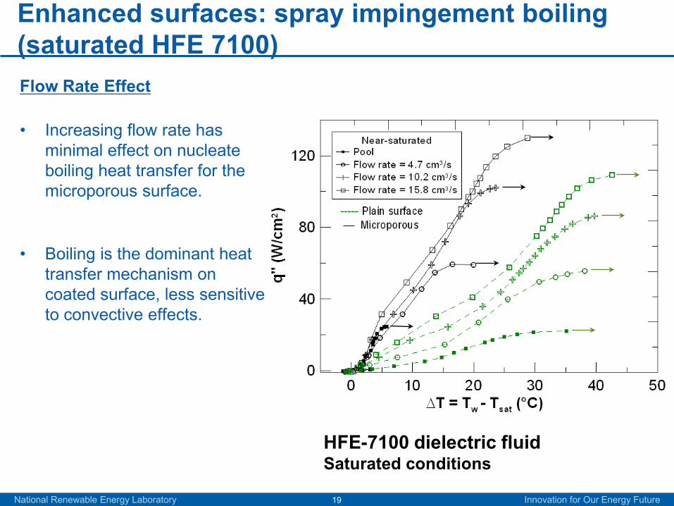
Enhanced surfaces: spray impingement boiling (saturated HFE 7100)
National Renewable Energy Laboratory Innovation for Our Energy Future18
Microporous Coating
• 100-300% increase in nucleate boiling (N.B.) heat transfer with respect to plain surface.
• 7-20% increase in the CHF with respect to plain surface.
• Coating structure (micro cavities of various sizes) enhances boiling heat transfer.
HFE-7100 dielectric Fluid Full cone spray @15.8 cm3/s (corresponds to 7 m/s velocity)
Enhanced surfaces: spray impingement boiling (saturated HFE 7100)
National Renewable Energy Laboratory Innovation for Our Energy Future19
Flow Rate Effect
• Increasing flow rate has minimal effect on nucleate boiling heat transfer for the microporous surface.
• Boiling is the dominant heat transfer mechanism on coated surface, less sensitive to convective effects.
HFE-7100 dielectric fluid Saturated conditions

0.1
1.0
1 10 100 1,000 10,000
R th
, j-a
(K/
W)
R"th, h-a (mm2 -K/W)
Semikron SKM
System level implication
Jet impingement•Submerged jet w/ skived surface decreases Rth-j-a by:
• 11% (Entire Package),
• 39% (DCD).
Two-phase•Pool boiling or spray cooling w/ microporous coating decreases Rth-j-
a by:• 16% (Entire Package),
• 61% (DCD).
Decrease in Rth-j-a will vary with different package configuration.
National Renewable Energy Laboratory Innovation for Our Energy Future20
Direct Cooled DBC
Entire Package
R”th,h-a: 2-phase, microporous
R”th,h-a: Sub. jet, skived

Future Worki. Reliability:
– Investigate degradation of plain surface when subject to jet impingement including nozzle degradation over time,
– Investigate ability of enhanced surface to remain effective under long term use.
ii. Synthesize/optimize additional coatings (e.g., using spray pyrolysis)
– Single-phase & two-phase applications (HFE7100, HFO-1234yf).
iii. Implement single-phase jet impingement with enhanced surfaces on a commercially available power electronics package (Semikron SKM).
iv. Implement two-phase cooling with enhanced surface in a package.
v. Implement flow visualization/characterization to understand underlying physics/mechanisms behind surface enhancements
– PIV/micro-PIV, High speed video & Schlieren shadowgraphs.
National Renewable Energy Laboratory Innovation for Our Energy Future21

National Renewable Energy Laboratory Innovation for Our Energy Future22
Thermal interface materials for power electronics applications

Thermal interface materials - project relevance• Excessive temperature can degrade the performance, life,
and reliability of power electronic components.
• Advanced thermal control technologies are critical to enabling higher power densities and lower system cost.
• Interfaces pose a major bottleneck to heat removal.
• Bonded interface materials (BIMs) based on solder are associated with thermomechanical reliability concerns under temperature cycling, as well as degradation at higher temperatures (>120°C).

The Problem
K. Stinson-Bagby, M.S. Thesis,Virginia Tech, 2002.
DBA substrate
Crack in the solder
layer
• Conventional TIMs do not meet thermal performance and reliability targets.
• Due to advantages from a packaging viewpoint, industry is trending toward bonded interfaces.
• Bonded interfaces such as solder degrade at higher temperatures, and are prone to thermomechanical failure under large temperature cycling.
BIM 2
Silicon die
Direct-bond-copper (DBC) or Direct-bond-aluminum (DBA)
Copper or Aluminum baseplate/coldplate
BIM 1

Sintered interfaces – based on silver nanoparticles
G.-Q. Lu, Virginia TechSynthesis of sintered interface
Sintered interface
Silver coating
Silver coating
Nickel coating
Nickel coating
Al or Cu
Al or Cu
• Sintered interfaces synthesized between silvered Cu-Cu and Al-Al disks (31.8 mm diameter) at Virginia Tech.
• A nickel coating (~2 µm) followed by silver coating (~ 2 µm) is applied on the copper and aluminum disks.
• For comparison, lead-free solder (SN100C) interface synthesized between Cu-Cu disks (31.8 mm diameter).
• Different thicknesses fabricated (20 ~ 200 microns).
Sintering cycleFixture

Sintered interfaces – preliminary experimental results
Samples Thickness(µm)
Resistance(mm2K/W)
SilveredCu-Cusinteredinterface
20 5.8
27 8.0
64 5.4
SilveredAl-Alsinteredinterface
28 14.9
103 25.2
144 5.0
Cu-Cusolderedinterface(SN100C)
80 1.0
150 4.8
200 3.7
• The thermal resistance tests were performed using the NREL ASTM TIM apparatus– Average sample
temperature ~ 65°C, pressure is 276 kPa (40 psi).
• The silvered Cu-Cu sintered interface shows promising thermal performance.
• Results hint at some problems with the bonding of the silvered Al-Al interface.
• The lead-free solder (SN100C) interface initial thermal results are very promising.
ASTM test fixture

Thermoplastics with embedded carbon fibers
Sample
• Thermoplastic films (provided by Btech) bonded between 31.8 mm diameter copper disks.
• Promising thermal results (8 mm2K/W for 100 microns bondline thickness).
• Continuing work at NREL to further decrease contact resistance to approach target thermal performance, as well as characterize reliability.
Sequence of bonding steps
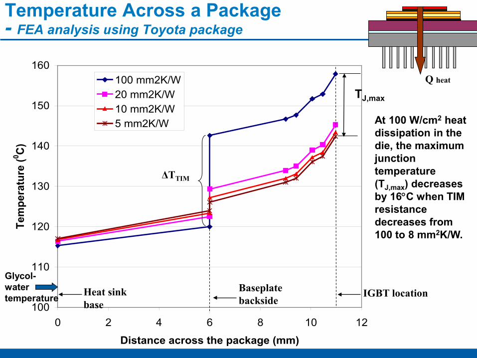
Temperature Across a Package- FEA analysis using Toyota package
Q heat
100
110
120
130
140
150
160
0 2 4 6 8 10 12
Distance across the package (mm)
Tem
pera
ture
(0 C)
100 mm2K/W20 mm2K/W10 mm2K/W5 mm2K/W
IGBT locationBaseplate backside
Heat sink base
Glycol-water temperature
ΔTTIM
TJ,max
At 100 W/cm2 heat dissipation in the die, the maximum junction temperature (TJ,max) decreases by 16°C when TIM resistance decreases from 100 to 8 mm2K/W.

Future Work
Remainder of FY10• Work with Btech to develop and test (via
ASTM steady-state approach) improved and reliable thermoplastics with embedded carbon fibers meeting target thermal performance
– Reduce contact resistance via ion-implantation and metal evaporation/sputtering techniques.
• In collaboration with Virginia Tech and Btech, synthesize and characterize various joints between DBA/DBC and aluminum/copper baseplate
– Synthesis of soldered, sintered, brazed and thermoplastic joints,
– Subject joints to thermal shock,– Thermal resistance measurement after
select cycles,– CSAM after select cycles,– High-potential test after select cycles,– Modeling of the joint thermomechanical
behavior (physics-of-failure) – end-of-life predictive model.
Tom Gennett, NREL
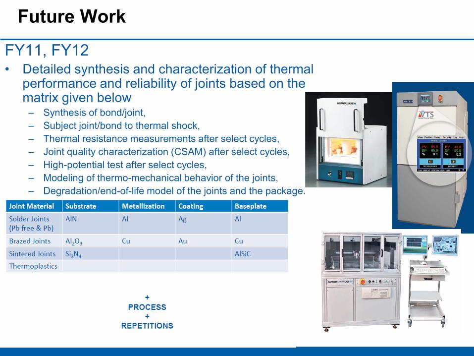
Future Work
FY11, FY12• Detailed synthesis and characterization of thermal
performance and reliability of joints based on the matrix given below
– Synthesis of bond/joint, – Subject joint/bond to thermal shock,– Thermal resistance measurements after select cycles,– Joint quality characterization (CSAM) after select cycles,– High-potential test after select cycles,– Modeling of thermo-mechanical behavior of the joints,– Degradation/end-of-life model of the joints and the package.
Summary
• Thermal management plays an important part in the cost of electric drives in terms of power electronics packaging.
• Very promising results from microporous coatings and skived surfaces in conjunction with single and two-phase flows.
• Sintered materials and thermoplastics with embedded fibers show significant promise as TIMs.
• Appropriate cooling technology depends on:• Package application,
• Reliability.
Acknowledgments
32
• Susan Rogers, U.S. Department of Energy• Kevin Bennion, Charles King, Mark Mihalic, Gilbert
Moreno, Michael O’Keefe, Suraj Thiagarajan, Travis Venson, Tom Gennett, Kim Jones, Bobby To (NREL)
• Wei Wang and Ronggui Yang (CU Boulder)• Jay Browne (Btech)• Gary Eesley (Delphi)• Greg Smith (GM)• Sy-Jenq Loong (Wolverine Tube Inc.)• Phil Tuma (3M)• G.Q. Lu (Virginia Tech)