Embed Size (px)
Citation preview
POWERModular High Power System
Up to 24000 Watts
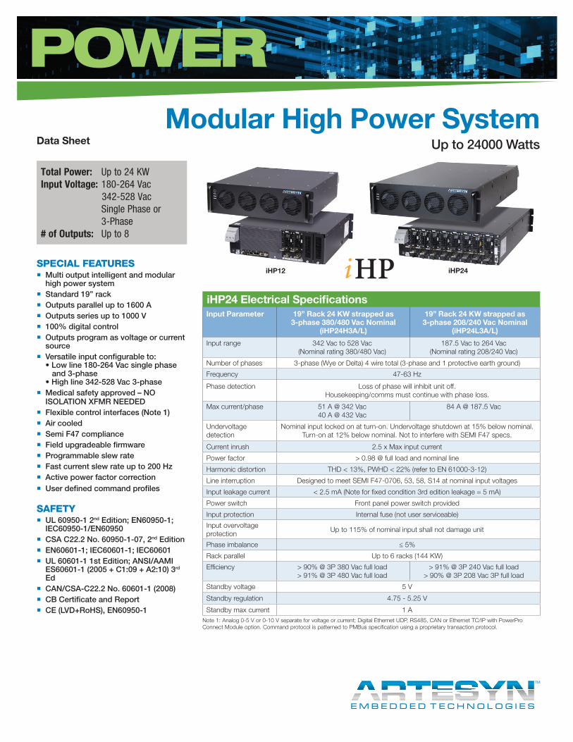
Total Power: Up to 24 KWInput Voltage: 180-264 Vac 342-528 Vac Single Phase or 3-Phase# of Outputs: Up to 8
SPECIAL FEATURES � Multi output intelligent and modular high power system
� Standard 19” rack � Outputs parallel up to 1600 A � Outputs series up to 1000 V � 100% digital control � Outputs program as voltage or current source
� Versatile input configurable to: • Low line 180-264 Vac single phase and 3-phase • High line 342-528 Vac 3-phase
� Medical safety approved – NO ISOLATION XFMR NEEDED
� Flexible control interfaces (Note 1) � Air cooled � Semi F47 compliance � Field upgradeable firmware � Programmable slew rate � Fast current slew rate up to 200 Hz � Active power factor correction � User defined command profiles
SAFETY � UL 60950-1 2nd Edition; EN60950-1; IEC60950-1/EN60950
� CSA C22.2 No. 60950-1-07, 2nd Edition � EN60601-1; IEC60601-1; IEC60601 � UL 60601-1 1st Edition; ANSI/AAMI ES60601-1 (2005 + C1:09 + A2:10) 3rd Ed
� CAN/CSA-C22.2 No. 60601-1 (2008) � CB Certificate and Report � CE (LVD+RoHS), EN60950-1
Data Sheet
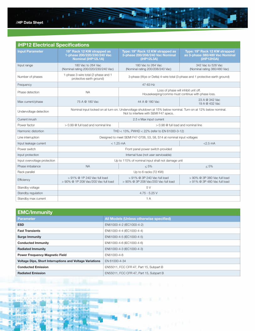
iHP24 Electrical Specifications Input Parameter 19” Rack 24 KW strapped as
3-phase 380/480 Vac Nominal (iHP24H3A/L)
19” Rack 24 KW strapped as 3-phase 208/240 Vac Nominal
(iHP24L3A/L)
Input range 342 Vac to 528 Vac (Nominal rating 380/480 Vac)
187.5 Vac to 264 Vac (Nominal rating 208/240 Vac)
Number of phases 3-phase (Wye or Delta) 4 wire total (3-phase and 1 protective earth ground)
Frequency 47-63 Hz
Phase detection Loss of phase will inhibit unit off. Housekeeping/comms must continue with phase loss.
Max current/phase 51 A @ 342 Vac 40 A @ 432 Vac
84 A @ 187.5 Vac
Undervoltage detection
Nominal input locked on at turn-on. Undervoltage shutdown at 15% below nominal. Turn-on at 12% below nominal. Not to interfere with SEMI F47 specs.
Current inrush 2.5 x Max input current
Power factor > 0.98 @ full load and nominal line
Harmonic distortion THD < 13%, PWHD < 22% (refer to EN 61000-3-12)
Line interruption Designed to meet SEMI F47-0706, 53, 58, S14 at nominal input voltages
Input leakage current < 2.5 mA (Note for fixed condition 3rd edition leakage = 5 mA)
Power switch Front panel power switch provided
Input protection Internal fuse (not user serviceable)
Input overvoltage protection
Up to 115% of nominal input shall not damage unit
Phase imbalance ≤ 5%
Rack parallel Up to 6 racks (144 KW)
Efficiency > 90% @ 3P 380 Vac full load > 91% @ 3P 480 Vac full load
> 91% @ 3P 240 Vac full load > 90% @ 3P 208 Vac 3P full load
Standby voltage 5 V
Standby regulation 4.75 - 5.25 V
Standby max current 1 A
Font: Minion Bold for VSMinion italic for i ; size for each is the sameCreated on Mac
Color: "i" 100% Blue, 50% Magenta, 0% Yellow, 0% Black"VS" - 100% Black
iHP12 iHP24
Note 1: Analog 0-5 V or 0-10 V separate for voltage or current; Digital Ethernet UDP, RS485, CAN or Ethernet TC/IP with PowerPro Connect Module option. Command protocol is patterned to PMBus specification using a proprietary transaction protocol.
iHP Data Sheet
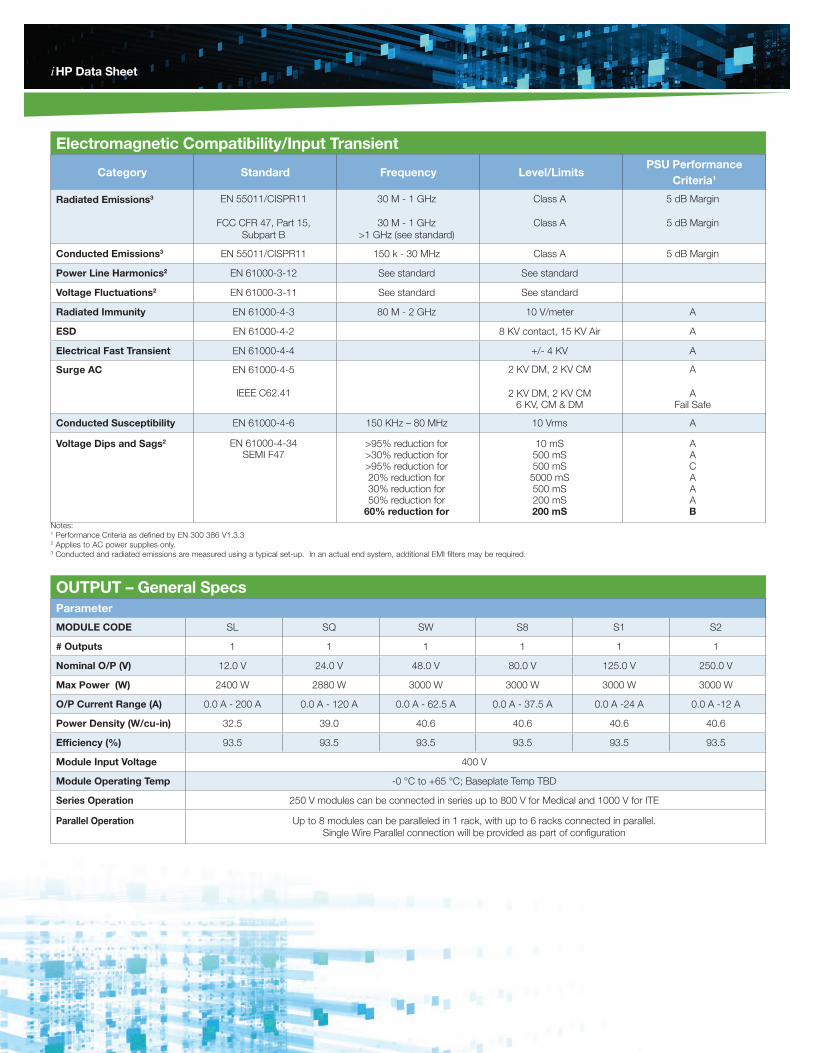
iHP12 Electrical Specifications Input Parameter 19” Rack 12 KW strapped as
1-phase 200/220/230/240 Vac Nominal (iHP12L1A)
Type: 19” Rack 12 KW strapped as 3-phase 200/208/240 Vac Nominal
(iHP12L3A)
Type: 19” Rack 12 KW strapped as 3-phase 380/480 Vac Nominal
(iHP12H3A)
Input range 180 Vac to 264 Vac (Nominal rating 200/220/230/240 Vac)
180 Vac to 264 Vac (Nominal rating 200/208/240 Vac)
342 Vac to 528 Vac (Nominal rating 380/480 Vac)
Number of phases1-phase 3-wire total (2-phase and 1
protective earth ground)3-phase (Wye or Delta) 4-wire total (3-phase and 1 protective earth ground)
Frequency 47-63 Hz
Phase detection NALoss of phase will inhibit unit off.
Housekeeping/comms must continue with phase loss.
Max current/phase 75 A @ 180 Vac 44 A @ 180 Vac23 A @ 342 Vac 19 A @ 432 Vac
Undervoltage detectionNominal input locked on at turn-on. Undervoltage shutdown at 15% below nominal. Turn-on at 12% below nominal.
Not to interfere with SEMI F47 specs.
Current inrush 2.5 x Max input current
Power factor > 0.99 @ full load and nominal line > 0.98 @ full load and nominal line
Harmonic distortion THD < 13%, PWHD < 22% (refer to EN 61000-3-12)
Line interruption Designed to meet SEMI F47-0706, 53, 58, S14 at nominal input voltages
Input leakage current < 1.25 mA <2.5 mA
Power switch Front panel power switch provided
Input protection Internal fuse (not user serviceable)
Input overvoltage protection Up to 115% of nominal input shall not damage unit
Phase imbalance NA < 5% < 5%
Rack parallel Up to 6 racks (72 KW)
Efficiency> 91% @ 1P 240 Vac full load
> 90% @ 1P 208 Vac/200 Vac full load> 91% @ 3P 240 Vac full load
> 90% @ 3P 208 Vac/200 Vac full load> 90% @ 3P 380 Vac full load> 91% @ 3P 480 Vac full load
Standby voltage 5 V
Standby regulation 4.75 - 5.25 V
Standby max current 1 A
EMC/ImmunityParameter All Models (Unless otherwise specified)
ESD EN61000-4-2 (IEC1000-4-2)
Fast Transients EN61000-4-4 (IEC1000-4-4)
Surge Immunity EN61000-4-5 (IEC1000-4-5)
Conducted Immunity EN61000-4-6 (IEC1000-4-6)
Radiated Immunity EN61000-4-3 (IEC1000-4-3)
Power Frequency Magnetic Field EN61000-4-8
Voltage Dips, Short Interruptions and Voltage Variations EN 61000-4-34
Conducted Emission EN55011, FCC CFR 47, Part 15, Subpart B
Radiated Emission EN55011, FCC CFR 47, Part 15, Subpart B
iHP Data Sheet
Electromagnetic Compatibility/Input Transient
Category Standard Frequency Level/LimitsPSU Performance
Criteria1
Radiated Emissions3 EN 55011/CISPR11
FCC CFR 47, Part 15, Subpart B
30 M - 1 GHz
30 M - 1 GHz >1 GHz (see standard)
Class A
Class A
5 dB Margin
5 dB Margin
Conducted Emissions3 EN 55011/CISPR11 150 k - 30 MHz Class A 5 dB Margin
Power Line Harmonics2 EN 61000-3-12 See standard See standard
Voltage Fluctuations2 EN 61000-3-11 See standard See standard
Radiated Immunity EN 61000-4-3 80 M - 2 GHz 10 V/meter A
ESD EN 61000-4-2 8 KV contact, 15 KV Air A
Electrical Fast Transient EN 61000-4-4 +/- 4 KV A
Surge AC
EN 61000-4-5
IEEE C62.41
2 KV DM, 2 KV CM
2 KV DM, 2 KV CM 6 KV, CM & DM
A
A Fail Safe
Conducted Susceptibility EN 61000-4-6 150 KHz – 80 MHz 10 Vrms A
Voltage Dips and Sags2
EN 61000-4-34 SEMI F47
>95% reduction for >30% reduction for >95% reduction for 20% reduction for 30% reduction for 50% reduction for
60% reduction for
10 mS 500 mS 500 mS
5000 mS 500 mS 200 mS 200 mS
A A C A A A B
Notes:1 Performance Criteria as defined by EN 300 386 V1.3.32 Applies to AC power supplies only.3 Conducted and radiated emissions are measured using a typical set-up. In an actual end system, additional EMI filters may be required.
OUTPUT – General SpecsParameter
MODULE CODE SL SQ SW S8 S1 S2
# Outputs 1 1 1 1 1 1
Nominal O/P (V) 12.0 V 24.0 V 48.0 V 80.0 V 125.0 V 250.0 V
Max Power (W) 2400 W 2880 W 3000 W 3000 W 3000 W 3000 W
O/P Current Range (A) 0.0 A - 200 A 0.0 A - 120 A 0.0 A - 62.5 A 0.0 A - 37.5 A 0.0 A -24 A 0.0 A -12 A
Power Density (W/cu-in) 32.5 39.0 40.6 40.6 40.6 40.6
Efficiency (%) 93.5 93.5 93.5 93.5 93.5 93.5
Module Input Voltage 400 V
Module Operating Temp -0 °C to +65 °C; Baseplate Temp TBD
Series Operation 250 V modules can be connected in series up to 800 V for Medical and 1000 V for ITE
Parallel Operation Up to 8 modules can be paralleled in 1 rack, with up to 6 racks connected in parallel. Single Wire Parallel connection will be provided as part of configuration
iHP Data Sheet
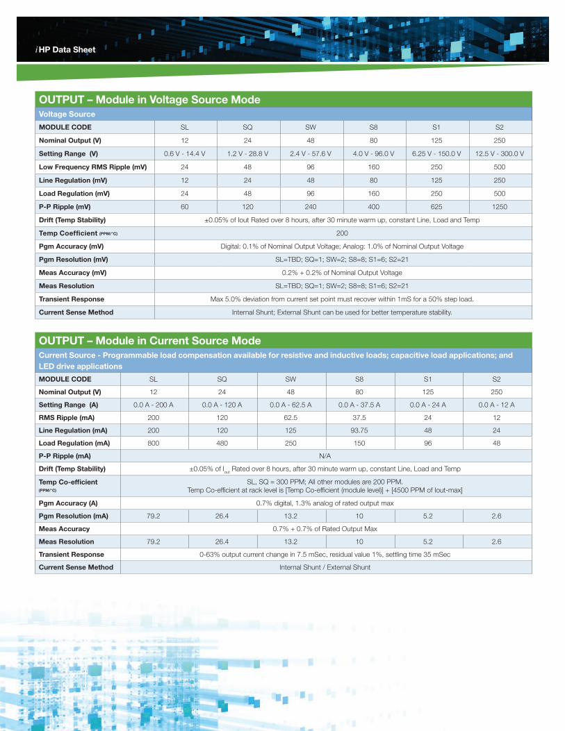
OUTPUT – Module in Voltage Source ModeVoltage Source
MODULE CODE SL SQ SW S8 S1 S2
Nominal Output (V) 12 24 48 80 125 250
Setting Range (V) 0.6 V - 14.4 V 1.2 V - 28.8 V 2.4 V - 57.6 V 4.0 V - 96.0 V 6.25 V - 150.0 V 12.5 V - 300.0 V
Low Frequency RMS Ripple (mV) 24 48 96 160 250 500
Line Regulation (mV) 12 24 48 80 125 250
Load Regulation (mV) 24 48 96 160 250 500
P-P Ripple (mV) 60 120 240 400 625 1250
Drift (Temp Stability) ±0.05% of Iout Rated over 8 hours, after 30 minute warm up, constant Line, Load and Temp
Temp Coefficient (PPM/°C) 200
Pgm Accuracy (mV) Digital: 0.1% of Nominal Output Voltage; Analog: 1.0% of Nominal Output Voltage
Pgm Resolution (mV) SL=TBD; SQ=1; SW=2; S8=8; S1=6; S2=21
Meas Accuracy (mV) 0.2% + 0.2% of Nominal Output Voltage
Meas Resolution SL=TBD; SQ=1; SW=2; S8=8; S1=6; S2=21
Transient Response Max 5.0% deviation from current set point must recover within 1mS for a 50% step load.
Current Sense Method Internal Shunt; External Shunt can be used for better temperature stability.
OUTPUT – Module in Current Source ModeCurrent Source - Programmable load compensation available for resistive and inductive loads; capacitive load applications; and LED drive applications
MODULE CODE SL SQ SW S8 S1 S2
Nominal Output (V) 12 24 48 80 125 250
Setting Range (A) 0.0 A - 200 A 0.0 A - 120 A 0.0 A - 62.5 A 0.0 A - 37.5 A 0.0 A - 24 A 0.0 A - 12 A
RMS Ripple (mA) 200 120 62.5 37.5 24 12
Line Regulation (mA) 200 120 125 93.75 48 24
Load Regulation (mA) 800 480 250 150 96 48
P-P Ripple (mA) N/A
Drift (Temp Stability) ±0.05% of Iout Rated over 8 hours, after 30 minute warm up, constant Line, Load and Temp
Temp Co-efficient (PPM/°C)
SL, SQ = 300 PPM; All other modules are 200 PPM. Temp Co-efficient at rack level is [Temp Co-efficient (module level)] + [4500 PPM of Iout-max]
Pgm Accuracy (A) 0.7% digital, 1.3% analog of rated output max
Pgm Resolution (mA) 79.2 26.4 13.2 10 5.2 2.6
Meas Accuracy 0.7% + 0.7% of Rated Output Max
Meas Resolution 79.2 26.4 13.2 10 5.2 2.6
Transient Response 0-63% output current change in 7.5 mSec, residual value 1%, settling time 35 mSec
Current Sense Method Internal Shunt / External Shunt
iHP Data SheetiHP Data Sheet
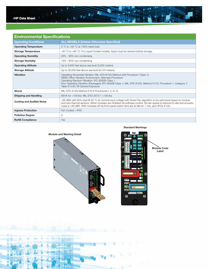
Environmental SpecificationsOperating Conditions ALL MODELS (Unless Otherwise Specified)
Operating Temperature 0 °C to +50 °C at 100% rated load.
Storage Temperature -40 °C to +85 °C. For Liquid Cooled models, liquid must be drained before storage
Operating Humidity 20% - 90% non condensing
Storage Humidity 10% - 95% non condensing
Operating Altitude Up to 9,842 feet above sea level (3,000 meters)
Storage Altitude Up to 30,000 feet above sea level (9,144 meters)
Vibration
Operating Sinusoidal Vibration MIL-STD-810G Method 528 Procedure I (Type 1): NEBS Office Vibration Environment, Alternate Procedure Operating Random Vibration: IPC-9592B Class 1 Non-Operating Vibration (Packaged): IPC-9592B Class 1; MIL-STD-810G, Method 514.6, Procedure 1, Category 7, Table 514.6C-VII General Exposure
Shock MIL-STD-810G Method 516.6 Procedures I, II, IV, VI
Shipping and Handling NSTA for <100 lbs; MIL-STD-2073-1 >100 lbs
Cooling and Audible Noise <65 dBA with 80% load @ 30 °C at nominal input voltage with Smart Fan algorithm to be optimized based on module and rack thermal sensors. When modules are inhibited via software control, the fan speed is reduced to idle and acoustic noise is <46 dBA. With modules off via front panel switch fans are at idle for 1 min, and off for 9 min.
Ingress Protection Fan Cooled = IP20
Pollution Degree 2
RoHS Compliance Yes
SWModule and Marking Detail
Standard Markings
Module Code Label
iHP Data Sheet
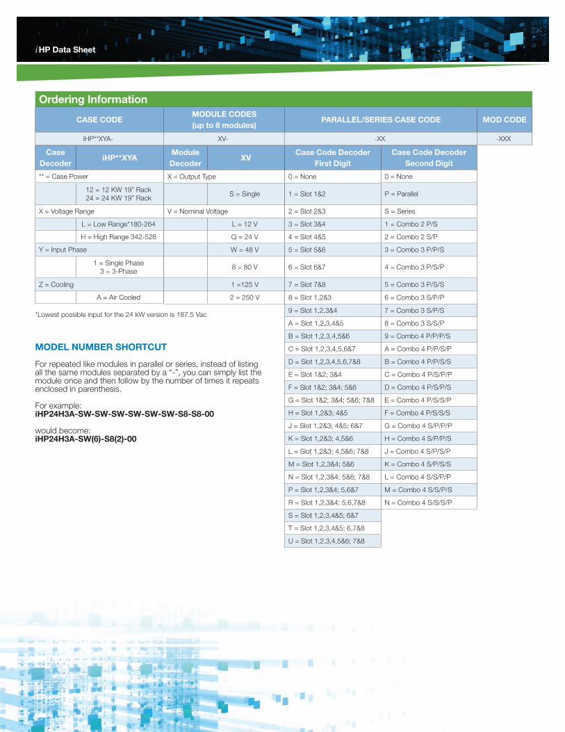
Ordering Information
CASE CODEMODULE CODES (up to 8 modules)
PARALLEL/SERIES CASE CODE MOD CODE
iHP**XYA- XV- -XX -XXX
Module Decoder
XV
X = Output Type
S = Single
V = Nominal Voltage
L = 12 V
Q = 24 V
W = 48 V
8 = 80 V
1 =125 V
2 = 250 V
Case Decoder
iHP**XYA
** = Case Power
12 = 12 KW 19” Rack 24 = 24 KW 19” Rack
X = Voltage Range
L = Low Range*180-264
H = High Range 342-528
Y = Input Phase
1 = Single Phase 3 = 3-Phase
Z = Cooling
A = Air Cooled
Case Code Decoder First Digit
0 = None
1 = Slot 1&2
2 = Slot 2&3
3 = Slot 3&4
4 = Slot 4&5
5 = Slot 5&6
6 = Slot 6&7
7 = Slot 7&8
8 = Slot 1,2&3
9 = Slot 1,2,3&4
A = Slot 1,2,3,4&5
B = Slot 1,2,3,4,5&6
C = Slot 1,2,3,4,5,6&7
D = Slot 1,2,3,4,5,6,7&8
E = Slot 1&2; 3&4
F = Slot 1&2; 3&4; 5&6
G = Slot 1&2; 3&4; 5&6; 7&8
H = Slot 1,2&3; 4&5
J = Slot 1,2&3; 4&5; 6&7
K = Slot 1,2&3; 4,5&6
L = Slot 1,2&3; 4,5&6; 7&8
M = Slot 1,2,3&4; 5&6
N = Slot 1,2,3&4; 5&6; 7&8
P = Slot 1,2,3&4; 5,6&7
R = Slot 1,2,3&4; 5,6,7&8
S = Slot 1,2,3,4&5; 6&7
T = Slot 1,2,3,4&5; 6,7&8
U = Slot 1,2,3,4,5&6; 7&8
Case Code Decoder Second Digit
0 = None
P = Parallel
S = Series
1 = Combo 2 P/S
2 = Combo 2 S/P
3 = Combo 3 P/P/S
4 = Combo 3 P/S/P
5 = Combo 3 P/S/S
6 = Combo 3 S/P/P
7 = Combo 3 S/P/S
8 = Combo 3 S/S/P
9 = Combo 4 P/P/P/S
A = Combo 4 P/P/S/P
B = Combo 4 P/P/S/S
C = Combo 4 P/S/P/P
D = Combo 4 P/S/P/S
E = Combo 4 P/S/S/P
F = Combo 4 P/S/S/S
G = Combo 4 S/P/P/P
H = Combo 4 S/P/P/S
J = Combo 4 S/P/S/P
K = Combo 4 S/P/S/S
L = Combo 4 S/S/P/P
M = Combo 4 S/S/P/S
N = Combo 4 S/S/S/P
*Lowest possible input for the 24 kW version is 187.5 Vac
MODEL NUMBER SHORTCUT
For repeated like modules in parallel or series, instead of listing all the same modules separated by a “-”, you can simply list the module once and then follow by the number of times it repeats enclosed in parenthesis.
For example: iHP24H3A-SW-SW-SW-SW-SW-SW-S8-S8-00
would become: iHP24H3A-SW(6)-S8(2)-00
iHP Data Sheet
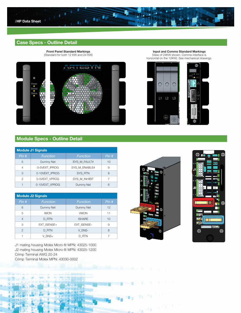
Case Specs - Outline Detail
Module Specs - Outline Detail
Front Panel Standard Markings (Standard for both 12 KW and 24 KW)
Input and Comms Standard Markings (View of 24KW shown. Comms interface is
horizontal on the 12KW). See mechanical drawings.
Module J1 Signals
Pin # Function Function Pin #
5 Dummy Net SYS_M_FAULT# 10
4 0-5VEXT_IPROG SYS_M_ENABLE# 9
3 0-10VEXT_IPROG SYS_RTN 8
2 0-5VEXT_VPROG SYS_M_INHIBIT 7
1 0-10VEXT_VPROG Dummy Net 6
Module J2 Signals
Pin # Function Function Pin #
6 Dummy Net Dummy Net 12
5 IMON VMON 11
4 D_RTN ISHARE 10
3 EXT_ISENSE+ EXT_ISENSE- 9
2 D_RTN V_SNS- 8
1 V_SNS+ D_RTN 7
J1 mating housing Molex Micro-fit MPN: 43025-1000J2 mating housing Molex Micro-fit MPN: 43025-1200Crimp Terminal AWG 20-24Crimp Terminal Molex MPN: 43030-0002
iHP Data SheetiHP Data Sheet
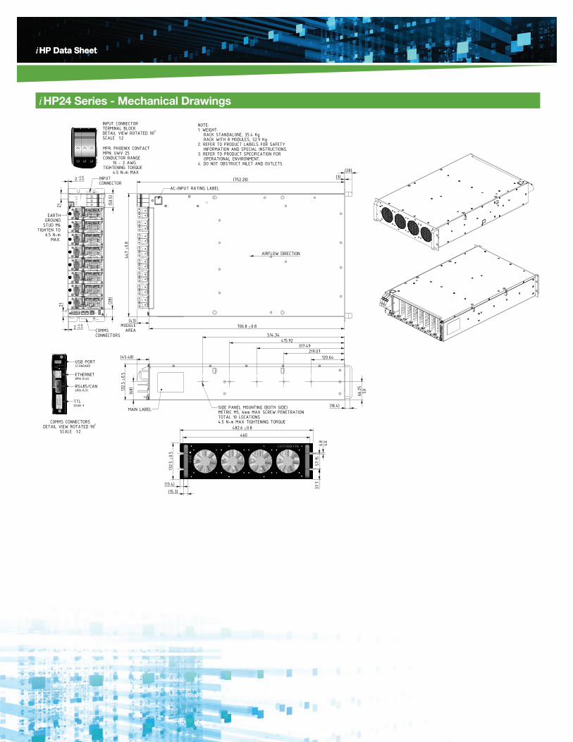
iHP24 Series - Mechanical Drawings
AIRFLOW DIRECTION
NOTE:1. WEIGHT: RACK STANDALONE, 35.4 Kg RACK WITH 8 MODULES, 52.9 Kg2. REFER TO PRODUCT LABELS FOR SAFETY INFORMATION AND SPECIAL INSTRUCTIONS.3. REFER TO PRODUCT SPECIFICATION FOR OPERATIONAL ENVIRONMENT.4. DO NOT OBSTRUCT INLET AND OUTLETS.
SIDE PANEL MOUNTING (BOTH SIDE)METRIC M5, 6mm MAX SCREW PENETRATIONTOTAL 10 LOCATIONS4.5 N-m MAX TIGHTENING TORQUE
MAIN LABEL
AREAMODULE
AC-INPUT RATING LABEL
COMMSCONNECTORS
EARTHGROUND
STUD M6TIGHTEN TO
6.5 N-mMAX.
INPUT CONNECTOR
COMMS CONNECTORSDETAIL VIEW ROTATED 90
SCALE 1:2
USB PORTSTANDARD
ETHERNET8PIN RJ45
RS485/CAN6PIN RJ11
TTLDSUB 9
INPUT CONNECTORTERMINAL BLOCKDETAIL VIEW ROTATED 90SCALE 1:2
MFR: PHOENIX CONTACTMPN: UWV 25CONDUCTOR RANGE 10 - 2 AWGTIGHTENING TORQUE 4.5 N-m MAX
132.5
0.5
(15.3)
482.6 0.8
37.7
6.8
4X
132.5
0.5
(45.48)
706.8 0.8(43)
447
0.8
2 +0.10 -0.25
2121
2 +0.10 -0.25
(28)
120.64
460
(13.4)
57.15
(18.4)
(752.28)
(28)
219.07317.49
415.92514.34
66.25
5X
(50.5)
(68)
(3)
iHP Data SheetiHP Data Sheet
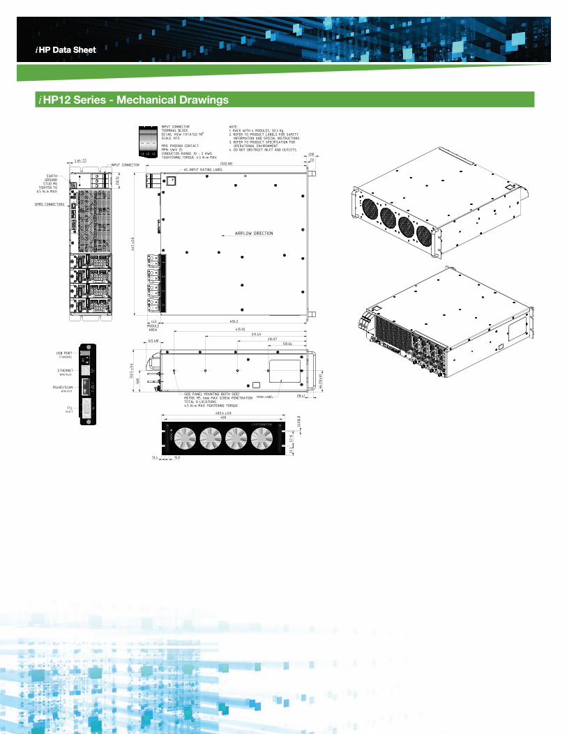
iHP12 Series - Mechanical Drawings
INPUT CONNECTORTERMINAL BLOCKDETAIL VIEW TOTATED 90SCALE: NTS MFR: PHOENIX CONTACTMPN: UWV 25CONDUCTOR RANGE: 10 - 2 AWGTOGHTENING TORQUE: 4.5 N-m MAX
NOTE:1. RACK WITH 4 MODULES, 30.3 Kg.2. REFER TO PRODUCT LABELS FOR SAFETY INFORMATION AND SPECIAL INSTRUCTIONS.3. REFER TO PRODUCT SPECIFICATION FOR OPERATIONAL ENVIRONMENT.4. DO NOT OBSTRUCT INLET AND OUTLETS.
MODULE AREA
AIRFLOW DIRECTION
AC-INPUT RATING LABEL
MAIN LABELSIDE PANEL MOUNTING (BOTH SIDE)METRIC M5. 6mm MAX SCREW PENETRATIONTOTAL 8 LOCATIONS.4.5 N-m MAX TIGHTENING TORQUE
COMMS CONNECTORS
EARTHGROUND
STUD M6TIGHTEN TO
6.5 N-m MAX
INPUT CONNECTOR
COMMS CONNECTORSDETAIL VIEW
USB PORT
ETHERNET
RS485/SCAN
TTL
A
STANDARD
8PIN RJ45
6PIN RJ11
DSUB 9
USB PORT
ETHERNET
RS485/SCAN
TTL
(28)(3)
(502.68)
447
0.8
(43)
(45.48)
132.5
0.6
(68)
120.64216.07
317.49415.92
(18.4)
66.25(4X
)456.2
2.05 +0.10 -0.25
(50.5)
460482.6 0.8
(4X)
6.8
57.15
37.7
15.813.4
wdsds
WORLDWIDE OFFICES Americas 2900 S.Diablo WayTempe, AZ 85282USA+1 888 412 7832
Europe (UK)Waterfront Business ParkMerry Hill, DudleyWest Midlands, DY5 1LXUnited Kingdom+44 (0) 1384 842 211
Asia (HK)14/F, Lu Plaza2 Wing Yip StreetKwun Tong, KowloonHong Kong+852 2176 3333
For more information: www.artesyn.com/power For support: [email protected]
www.artesyn.com
iHP Data Sheet
Artesyn Embedded Technologies, Artesyn and the Artesyn Embedded Technologies logo are trademarks and service marks of Artesyn Embedded Technologies, Inc. All other names and logos referred to are trade names, trademarks, or registered trademarks of their respective owners. Specifications are subject to change without notice. © 2018 Artesyn Embedded Technologies, Inc. All rights reserved. For full legal terms and conditions, please visit www.artesyn.com/legal.
iHP Data Sheet
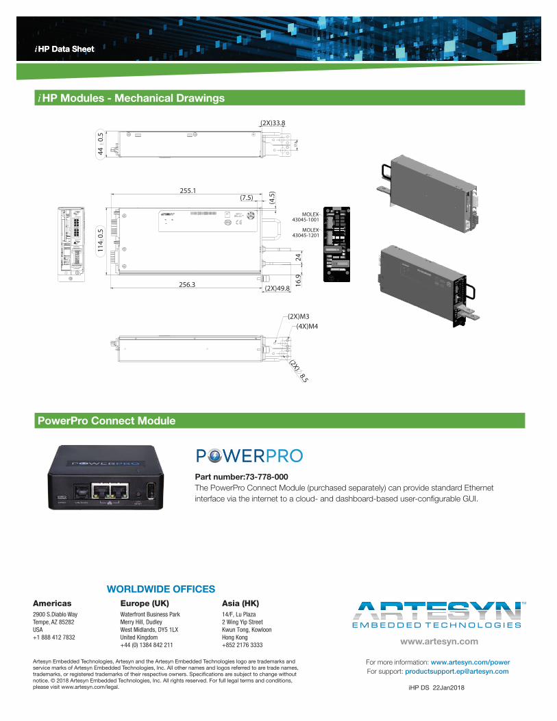
iHP Modules - Mechanical Drawings
(4X)M4(2X)M3
MOLEX43045-1001
MOLEX43045-1201
2416
.9
256.3 (2X)49.8
114
0.5
255.1
(2X)8.5
17.6
(2X)33.8
44
0.5
(7.5)
(4.5
)
iHP DS 22Jan2018
Part number:73-778-000 The PowerPro Connect Module (purchased separately) can provide standard Ethernet interface via the internet to a cloud- and dashboard-based user-configurable GUI.
PowerPro Connect Module