Embed Size (px)
Citation preview

POWER FACTOR CONTROLLERRG3-12C/CS
SUMMARY
Precautions for Safe Use and Installation.......................................................................................................1
Important Note for System Connection .............................................................................................................1
1. INTRODUCTION ..........................................................................................................................................................................2
1.1 General Information ............................................................................................................................................2
1.2 Front Panel .................................................................................................................................................................2
1.3 Rear Panel ..............................................................................................................................................................4
2. INSTALLATION OF RG3-12C/CS.....................................................................................................................5
2.1 Commissioning of RG3-12C/CS ..........................................................................................................................5
2.2 Capacitor Sequence Process ...........................................................................................................................................5
3. SETTINGS .................................................................................................................................................................5
3.1 Manual Operation, Automatic Capacitor Recognition Mode and Automatic Connection Recognition Mode...........5
3.2 Target Cosj and Cosj2Value Setting ....................................................................................................................7
3.3 Last Capacitor Step Number Setting..................................................................................................................................7
3.4 Selection of Proper Switching Sequence.........................................................................................................................8
3.5 Switching on&off Time for Capacitor Steps and Discharge Time Settings.................................................................8
3.6 Power Value and Connection Type Settings for Capacitors ........................................................................................10
3.7 Current and Voltage Transformer Ratio Settings .......................................................................................................12
3.8 Reset Settings .....................................................................................................................................................14
3.9 Alarm Settings .....................................................................................................................................................15
3.10 Fan Relay Settings .....................................................................................................................................................21
3.11 Resetting the Energy Counters and Entering the Energy Values..................................................................................23
3.12 Computer Communication Settings .................................................................................................................................24
3.13 Password Activation and Change Settings .............................................................................................................26
4. DISPLAYING OF INSTANTANEOUS VALUES ......................................................................................................28
Cosj, Total Cosj, Voltages ................................................................................................................................28
Currents, Active Powers, Total Active Powers ...........................................................................................................29
Reactive Powers, Total Reactive Powers, Apparent Powers, Total Apparent Powers......................................30
Active Import Energy, Active Export Energy, Inductive Reactive Energy, Capacitive Reactive Energy,
Temperature, Error Codes ................................................................................................................................................31
5. APPENDIX .......................................................................................................................................................................32
Error Messages ................................................................................................................................................32
Register Table ..................................................................................................................................................33
Capacitor Calculation Table ............................................................................................................................................38
Technical Features ..............................................................................................................................................39
Menu Map .............................................................................................................................................................

Precautions for Safe Use and Installation
Consult the operating instructions before using the equipment. Following these precautions is a must for an error-free operation and maintaining the eligibility for a warranty.Therefore, please read this manual carefully before commissioning and using the RG3-12C/CS.
1)2)3)4)
5)6)7)8)9)10)
POWER FACTOR CONTROLLERRG3-12C/CS
ATTENTION!
No responsibility is assured by the manufacturer or any of its subsidiaries for any consequences rising out ofdisregarding these precautions while handling the RG3-12C/CS.
Important Note for System Connection.
First, connection type of auxiliary supply, voltage measurement and current measurement input must be 3 phase-neutral. The device will not operate properly if these connections are not done.A 3-phase capacitor must always be connected to the first step. Providing that this connection is followed for thefirst capacitor step, 3-phase or single phase capacitor banks can be connected to the other steps in any orderaccording to your systems needs.
1)
2)
Do not energise the device before verifying terminal connections.
1
Maintenance, installation and operation of RG3-12C/CS must be performed only by the qualified electricians.Do not operate the device in undervoltage conditions.Do not open the RG3-12C/CS�s housing. There are no user servicable parts inside it.RG3-12C/CS is connected to the network by means of a current transformer. Do not disconnect the current transformerterminals. If you disconnect them, be sure to short-circuit the terminals or connect them to another parallel load whichhas a low impedance. Otherwise, dangerously high voltage at the secondary side of current transformer may causean electric shock.Do not use this product for any other purpose than its original task.When device is connected to the network, do not remove the front panel.Do not clean the device with solvent or similar items. Only clean with a dried cloth.Verify terminal connections before commissioning.Electrical equipment should be serviced only by your competent seller.Device is only suitable for panel mounting.
Generator Input ConnectionThe connection to the generator input of the device must be done in a way that the energy comes to the system after thegenerator connection to the network has been established. Otherwise, the device will switch to generator mode when thegenerator is started for maintanence purposes.If there is a voltage between 110-250 VAC present on the generator inputs of the device, the target �Cosj� set on the deviceis deactivated and target �Cosj2� is activated. Then the device starts the compensation according to target Cosj2. Thisoperation mode continues until the voltage on the generator input is disappeared.
Monitoring the measured temperatureIn order make a correct measurement, J type (Fe/Cu-Ni) thermocouple must be connected to �TEMP� terminal and keepworked at least 30 min. In order to observing the measured environmental temperature, press UP/DOWN buttons untill thedisplaying the �xxx.x � value.NOTE: RG3-12C/CS temperature measurement feature is optional.

1.2 Front PanelOn the front panel; 3 display lines with four digits which consist of 7segments, 4 buttons, alarm, capacitor step and display LEDs exist.Measured parameters are observed in the related displays. Displayedvalues for related parameters are selected via indicator leds. When analarm occurs, related alarm LED blinks. 12 capacitor step LEDs indicatewhich capacitor step is switched on. Detailled information about buttons,display, alarm and capacitor step LEDs will be explained in the comingsections.
POWER FACTOR CONTROLLERRG3-12C/CS
1.2.a Button Functions
UP
DOWN:
In the observation mode, they are used forswitching between observed parameters. Inthe programming mode, they are used forbrowsing the menu choices and changingthe parameter values.
In the observation mode, it is used to switchbetween harmonic measurement mode andinstant value measurement mode. In theprogramming mode, it is used to return tothe previous menu or exit without saving anycommitted changes.
In the observation mode, it is used to showthe harmonic value of the measuredparameter. If it is pressed for 3 seconds,programming mode appears. In theprogramming mode, it is used to enter to amenu or confirm the data entry.
1. INTRODUCTION1.1 General InformationIn todays world, the reactive loads on a network continue to increase withthe contracted power rise. The increase of the power on transformers,transmission lines and generators caused a rise in the reactive power levelsjust as much and maybe more than the active power levels. To prevent anyoverloads and under voltage conditions, the compensation of the reactiveloads became a necessity in todays energy network.Power factor controllers monitor the reactive power of a plant and try tomatch the power factor value which is defined as the ratio of the activepower(W) to the apparent power(VA) to a power factor valuewhich is definedon the device by the user.RG3-12C/CS power factor controller is designed for reactive powercompensation in single phase and 3-phase systems.RG3-12C/CS compensates each phase separately and so, this makesRG3-12C/CS series a unique solution for unbalanced load compensation.In order to achieve this feat, single phase and 3-phase capacitor stepsmust be connected to the device at the same time.
Measured Parameters :Phase Voltage (L1,2,3-N) MeasurementPhase Current (L1,2,3-N) MeasurementCosj Value (L1,2,3-N) MeasurementAverage (Ind./Cap.) Cosj Value MeasurementActive Power (W), Reactive Power (VAr), Apparent Power(VA) MeasurementTotal Active Power (Ind./Cap.), Total Reactive Power(Ind./Cap.), Total Apparent Power (Ind./Cap.) MeasurementActive Energy (Wh-Import/Export), Reactive Energy(VArh-Import/Export) MeasurementMeasuring up to 19th Harmonic (V, I, W, VAr, VA) 1,3,5,.....,19
*Temperature Measurement
1)2)3)4)5)
6)
7)
8)9)
*Optional
2
Type PR16(144x144)
143
99
121
138.4
144
18
34.5
67
1) Panel cut-out dimension must be 139 mm x 139 mm(Type PR16).2) Before installation, remove the mounting brackets.3) Mount the device to the front panel.4) Insert the mounting brackets.5) Voltage and current terminals are designed for cableswith a cross-section of 2,5 mm2 but these terminals aresuitable for cables with cross-sections up to 4 mm2.6) CAT5 cable is recommended for RS-485 input terminal.
Excessive force can damage the device.Turn the screw into the terminals and tighten until theRG3-12C/CS is secured in place.
DIMENSIONS
225.5
228.7
223.4
ESC
SET
:
:

225.5
228.7
223.4
1.2.b Front Panel Functions
POWER FACTOR CONTROLLERRG3-12C/CS
In order to enter to the menu, �SET� buttonmust be pressed for 3 seconds. In the followingsections, �enter the menu� means press the SETbutton for 3 seconds.
3
2423 22
12
13
14
15
16
17
18
19
21
11
4
20
7
6
5
26
27
29
3031
25
91
3
2
28
8
10
32
1. L12. L23. L34. Up Button
5. Esc Button
6. Set Button
7. Down Button
8. M LED
9. k LED
10. 1,2,3,.......,12 LEDs
11. SET Menu
12. OTO/MAN LED
13. Cosj LED
14. STEP / V LED
::::
:
:
:
:
:
:
:
:
:
:
Display for phase 1.Display for phase 2.Display for phase 3.In the menu and measuring mode, is is used tomove upwards. In the setup mode, it is used toincrease the adjusted value.In the menu, it is used to return to the previousprocess or exit from a menu. In the measuringmode, it is used to leave the harmonicobservation mode.It is used to enter to the menu, to access a sub-menu and save the committed changes. In themeasurement mode, it is used to monitor theharmonic values of voltage, current and powerparameters.In the menu and measuring mode, is is used tomove downwards. In the setup mode, it is usedto decrease the adjusted value.It indicates that the measured value is in megaunits and the observed value is multiplied with106.It indicates that the measured value is in kilounits and the observed value is multiplied with103.These LEDs indicate the state of correspondingcapacitor steps of the device. If a capacitorstep is activated, the corresponding step LEDis lit.Programmable menus which are set by pressingSET button for 3 seconds.This LED indicates if the operating mode isautomatic or manual. If it is continuously on, thedevice is operating in Automatic Mode. If itblinks, the device is operating in Manual Mode.The color of this LED is green.If Cosj LED is on in the menu, target Cosjvalue can be set between Inductive 0,8 -Capacitive 0,8. If Cosj LED is on in themeasuring mode, Cosj values of relatedphases are displayed.If �STEP/V� LED is on in the menu, step numbercan be set in the menu. If �STEP/V� LED is onin the measuring mode, the phase voltagesappear on their corresponding phase displays.
15. PROGRAM / I LED
16. TIME / W LED
17. Capacitors/VAr LED
18. NETWORK/VA LED
19. RESET / HAR LED
20. ALARM / h LED
21. RS-485
22. C- LED
23. NORMAL LED
24. C+ LED
25.
26.
27.
28.
29.
30.
31.
32.
:
:
:
:
:
:
:
:
:
:
:
:
:
:
:
:
:
:
If �PROGRAM/I� LED is on in the menu; theswitching sequence can be set in the menu. If�PROGRAM/I� LED is on in the measuring mode,the phase currents appear on theircorresponding phase displays.If �TIME/W� LED is on in the menu; dischargetime, switch on delay time and switch off delaytime can be adjusted in the menu. If �TIME/W�LED is on in the measuring mode, active powerand total active power (Ind./Cap.) values of thephases are displayed on the correspondingdisplays.If �CAPACITORS/VAr� LED is on in the menu,the values and connection types(R, S,T, RST)o f the capac i to rs can be se t . I f�CAPACITORS/VAr� LED is on in the measuringmode, reactive power and total reactive power(Ind./Cap.) values of the phases are displayedon the corresponding displays.If �NETWORK/VA� LED is on in the menu; currenttransformer ratio(Ctr), voltage transformerratio(Vtr) and calculation method can be set. If�NETWORK/VA� LED is on in the measuringmode, apparent power and and total apparentpower values of the phases are displayed onthe cor responding phase d isp lays.Press SET button for 3 seconds and enter themenu. Select the �RESET/HAR� LED to erasethe energy values, reset the reactive energyratios and alarms.Press SET button for 3 seconds and enter themenu. Select �ALARM/h� LED to set theboundary values for alarms(overvoltage,reactive/active ratio, temperature andharmonics).In this menu; settings related to the RS-485communication protocol(baudrate, address,parity) are set.This LED indicates that RG3-12C/CS is waitingto switch off capacitor steps.This LED indicates that RG3-12C/CS will notswitch any capacitor steps on or off.This LED indicates that RG3-12C/CS is waitingto switch on capacitor steps.Incase of a failure, alarm relay switches on andalarm LED lights up.In case of a connection failure, this LED lightsup.If reactive energy ratios go beyond user-definedvalues, this LED lights up.If voltage harmonic ratios go beyond user-defined values, this LED lights up.When target Cosj value is not reached eventhough all of the capacitor steps are switchedon(insuff icient step power for targetcompensation), this LED lights up.If there isn�t a capacitor connected to a step,capacitor step failure LED lights up.If the voltage value exceeds the user-definedovervoltage, this LEDC lights up.10 seconds after the measured temperaturevalue exceeds the user-defined fan operatingvalue, fan LED lights up.
POWER FACTOR CONTROLLERRG3-12C/CS
Warnings :
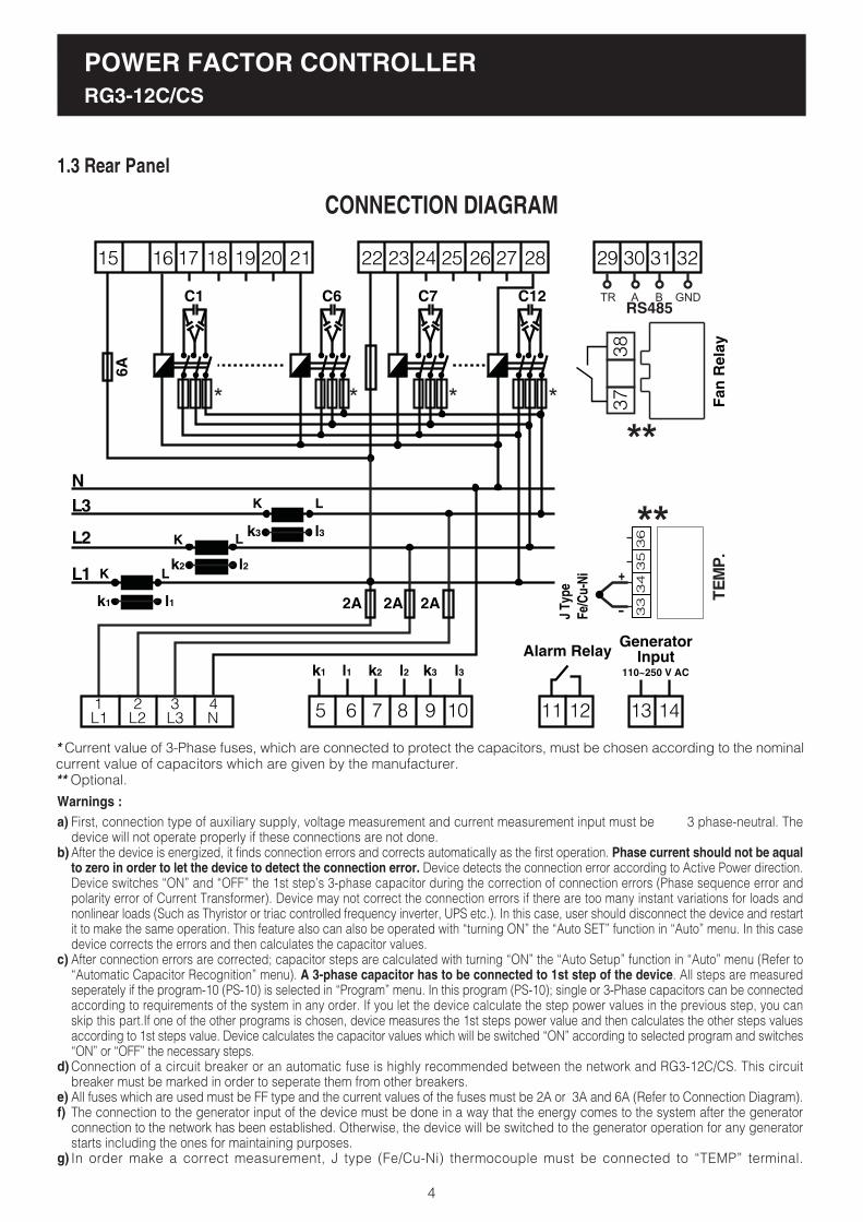
1.3 Rear Panel
4
CONNECTION DIAGRAM
* Current value of 3-Phase fuses, which are connected to protect the capacitors, must be chosen according to the nominalcurrent value of capacitors which are given by the manufacturer.** Optional.
15 16 17 18 19 20 21
5 6 7 8 9 10
K L
K L
K L
6A
Alarm Relay
11 12
C1 C6 C7 C12
22 23 24 25 26 27 28
2A 2A 2A
k1
l1
k2 l2 k3 l3
k1
l2k2
l3k3
l1
29 30 31 32
N
L3
L2
L1
****
GeneratorInput
13 14
110~250 V AC
1 2 3 4L1 L2 L3 N
First, connection type of auxiliary supply, voltage measurement and current measurement input must be 3 phase-neutral. Thedevice will not operate properly if these connections are not done.After the device is energized, it finds connection errors and corrects automatically as the first operation. Phase current should not be aqualto zero in order to let the device to detect the connection error. Device detects the connection error according to Active Power direction.Device switches �ON� and �OFF� the 1st step�s 3-phase capacitor during the correction of connection errors (Phase sequence error andpolarity error of Current Transformer). Device may not correct the connection errors if there are too many instant variations for loads andnonlinear loads (Such as Thyristor or triac controlled frequency inverter, UPS etc.). In this case, user should disconnect the device and restartit to make the same operation. This feature also can also be operated with �turning ON� the �Auto SET� function in �Auto� menu. In this casedevice corrects the errors and then calculates the capacitor values.After connection errors are corrected; capacitor steps are calculated with turning �ON� the �Auto Setup� function in �Auto� menu (Refer to�Automatic Capacitor Recognition� menu). A 3-phase capacitor has to be connected to 1st step of the device. All steps are measuredseperately if the program-10 (PS-10) is selected in �Program� menu. In this program (PS-10); single or 3-Phase capacitors can be connectedaccording to requirements of the system in any order. If you let the device calculate the step power values in the previous step, you canskip this part.If one of the other programs is chosen, device measures the 1st steps power value and then calculates the other steps valuesaccording to 1st steps value. Device calculates the capacitor values which will be switched �ON� according to selected program and switches�ON� or �OFF� the necessary steps.Connection of a circuit breaker or an automatic fuse is highly recommended between the network and RG3-12C/CS. This circuitbreaker must be marked in order to seperate them from other breakers.All fuses which are used must be FF type and the current values of the fuses must be 2A or 3A and 6A (Refer to Connection Diagram).The connection to the generator input of the device must be done in a way that the energy comes to the system after the generatorconnection to the network has been established. Otherwise, the device will be switched to the generator operation for any generatorstarts including the ones for maintaining purposes.In order make a correct measurement, J type (Fe/Cu-Ni) thermocouple must be connected to �TEMP� terminal.
a)
b)
c)
d)
e)f)
g)
Fa
n R
ela
y
38
37
**
33
34
35
36
J Ty
peFe
/Cu-
Ni +
**
TE
MP
.
GNDBTR A
RS485

POWER FACTOR CONTROLLERRG3-12C/CS
2. INSTALLATION OF RG3-12C/CS
When RG3-12C/CS is energised for the first time, if the power valueof any phase is negative, it switches on&off the first capacitor stepautomatically to recognize the connection error and records the connections.
Later, automatic setup (Refer to page 6 - Automatic setup) is selectedfrom the menu in order to recognise the connections and connectedcapacitor steps automatically.
After automatic recognition, RG3-12C/CS checks all capacitor stepvalues. If variable loads exist in the system, these variable loads must bedisconnected first and then automatic setup process must be done.Otherwise, power factor controller may not measure capacitor step powerscorrectly. Capacitor step powers and connection types also can be enteredto the power factor controller manually.(Refer to page 10 - Setting of the capacitor�s connection and power values)
After recognising the capacitor step powers, target Cosjvalue is set in order to start the compensation. Factory set value for targetCosj is ind. 1.000 and Cosj2 is ind. 0.900
Note: PFC decreases the switching on&off time to 3 seconds inAutomatic Setup mode but discharge time is not changed. After theautomatic setup process, set values become valid.
After the device is energised, it finds connection errors and correctsthem automatically. Power values of the capacitor steps are measuredautomatically according to program selection. If PS-10 program isselected, power values of all capacitor steps are measured (Refer toProgram Section). If any other program is selected, device measuresfirst capacitor step value and then calculates other capacitor stepsaccording to the selected program. For this reason, a 3-phase capacitormust be connected to the first step. Single phase and/or 3-phasecapacitors can be connected in any order to the other steps. After thedevice calculates and saves the capacitor values, it will switch them onand off when needed.
2.1 Commissioning of RG3-12C/CS
2.2 Capacitor Sequence Setting
3. SETTINGS
3.1.a Manuel Operation Mode SettingRG3-12C/CS has two operating modes which are automaticand manual. The operation mode is choosed by selecting the�Auto Operati� option as on(automatic mode) or off(manualmode). Manual mode is used for test purposes. In this mode,capacitor steps are switched on&off to test relay outputs. Inmanual mode, capacitor steps are switched on with �SET�button and switched off with �ESC� button. The conditions ofthe steps can be monitored from the 12 step LEDs on the frontpanel. C+ LED lights up when a step is switching on and C-LED lights up when a step is switching off. Factory set valuesfor switching on (t-on) and switching off (t-of) time are 10 sec.These values can be changed by the �dELy� menu (Refer toSwitching on&off Time for Capacitor Steps and DischargeTime Settings). In manual mode; step numbers, which will beswitched on&off, can be programmed in �StEP� menu (Referto Step Number Setting). Even if manual mode is selected,device switches to automatic mode after 5 minutes continuesto operate in this mode.
3.1 Manual Operation Mode, Automatic CapacitorRecognition Mode and Automatic Connection ControlMode
5
Press the �SET� button for 3 sec. in order to enter to the menu.
Press �SET� button to set the parameters in �Auto� menu option.
Press �UP� or �DOWN� button. To select the automatic operating mode,choose �on� with �UP� or �DOWN� buttons and press �SET� button. Toselect the manual operating mode, choose �oF� with �UP� or �DOWN�buttons and press �SET� button.
The first setting in this menu is the operation mode(Operati). The operationmode of the device is selected according to this options on or off selection.Press �SET� button to change this setting.
Numerical values of the parameters are set via buttons in thedisplay. The blinking digit indicates which digit will be set.Numerical value of the related digit is increased or decreased via�UP� or �DOWN� button. To set the next digit, �SET� button isused. To go back to the previous digit, �ESC� button is used.
When automatic mode is selected, AUTO/MAN LED lights upcontinuously.When manual mode is selected, AUTO/MAN LED blinks.
Warning: Device warns user by blinking (short ON, long OFF)the LED of the capacitor steps which will be switched on. Alsodevice warns user by blinking (long ON, short OFF) the LEDof the capacitor steps which will be switched off.
For proper operation; 3-Phase, neutral, voltage and current terminalsmust be connected as shown in the connection diagram. Device does notwork properly without 3-phase connection.
After the connection of the current and voltage lines, connect thecapacitors to the device. The most important point is connecting a 3-phasecapacitor to the first step. Remaining single phase and 3-phase capacitorscan be connected to the other steps in any order and power values.
After the connection of capacitor steps; J-Type 0-400 V thermocouplemust be connected if temperature measurement function will be used(Temperature measurement feature is optional).
Lastly, computer communication connection must be done.Do not energise the device before verifying the connections.Always connect a 3-phase capacitor to the 1st step.
3 sec.

POWER FACTOR CONTROLLERRG3-12C/CS
6
3.1.b Automatic Capacitor Recognition Mode SettingWhen the device is energised for the first time, it checks for connectionerrors. If there is a faulty connection, it corrects this fault in itself. In orderfor the device to correct a connection fault, 3-phase voltage and currentconnections of the device must be done.
NOTE: If there are other loads than compensation connected to thesystem, the device may not find the connection at the first try andmay need several tries. However, if the device is unable to completethe automatic connection process step calculation process shouldn�tbe done. In order for the calculated capacitor powers to be accurate,the current and voltage transformer ratios have to be enteredcorrectly before the automatic capacitor recognition process. Ifthese ratios are not entered by the user, they will be set as �1� bythe device and the capacitor step powers will be calculated accordingto these values(Refer to page 12-CT and VT Ratio Settings).
After any connection faults are corrected by the device; if �Auto Setup�option is set as �on�, the device calculates the capacitor step powersaccording to the selected program. If 10th program(P-10) is selected , allof the capacitor step powers are measured seperately. If any other programis selected, the device measures only the first capacitor step power andthen calculates the other step powers according to the selectedprogram(Refer to page 7-Step Number Setting).
NOTE: If the option �on� is selected in the automatic setup menu,the automatic capacitor recognition will start without exiting themenu.The step powers which are calculated after this process must alwaysbe checked.
Select �on� or �of� using the �UP� and�DOWN� buttons(Select �on� for automaticcapacitor recognition).
In Auto Operatý menu, choose �Auto Setup� menu by pressingthe �UP� button.
The 2nd setting in this menu is the Auto Setup setting. Theautomatic setup will or will not start according the options �on�or �off� selection. To change this setting, press the SET button.
3.1.c Automatic Connection Recognition Mode Setting
This option is used for activating or deactivating the connectionrecognition mode when the device is energised. It is activated asfactory default. In applications with a generator, the voltage andcurrent information may not arrive to the device properly dependingon the transfer panels design and delay when the system is switchedfrom generator to the network power. When this transition occurs,the device may find a connection fault. Therefore, it is recommendedto turn this option off after the setup is completed.
Select the Auto Setup option in the Auto Operatý menu with�DOWN� button.
Connection correction is activated or deactivated depending onthe �on� or �off� position of the Auto connection option. To changethis setting press the �SET� button.
When Auto connection is �on�, the device controls its connectionautomatically at start-up and corrects any existing measurementinput errors. If this option is �of�, automatic connection correctionis deactivated. Using �UP� ve �DOWN� buttons, select �on�or�of�.
If you want to leave the setup menu without making any otherchanges, press the �ESC� button until �SAVE SEt yES� showson the screen. If you want to save the changes, press the �SET�button. If not, press the �ESC� button.
SAUE
POWER FACTOR CONTROLLERRG3-12C/CS
7
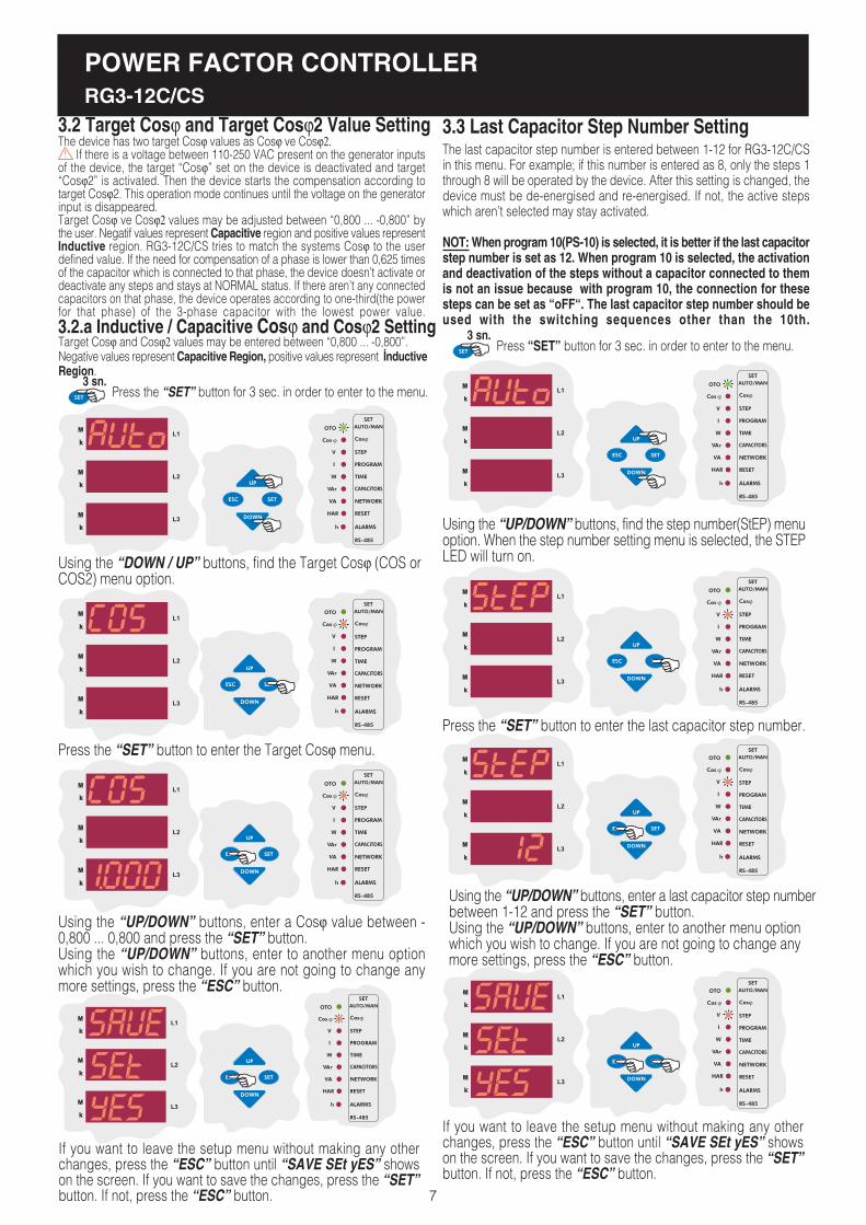
The last capacitor step number is entered between 1-12 for RG3-12C/CSin this menu. For example; if this number is entered as 8, only the steps 1through 8 will be operated by the device. After this setting is changed, thedevice must be de-energised and re-energised. If not, the active stepswhich aren�t selected may stay activated.
NOT: When program 10(PS-10) is selected, it is better if the last capacitorstep number is set as 12. When program 10 is selected, the activationand deactivation of the steps without a capacitor connected to themis not an issue because with program 10, the connection for thesesteps can be set as �oFF�. The last capacitor step number should beused with the switching sequences other than the 10th.
3.3 Last Capacitor Step Number Setting
Press �SET� button for 3 sec. in order to enter to the menu.
Using the �UP/DOWN� buttons, find the step number(StEP) menuoption. When the step number setting menu is selected, the STEPLED will turn on.
SAUE
If you want to leave the setup menu without making any otherchanges, press the �ESC� button until �SAVE SEt yES� showson the screen. If you want to save the changes, press the �SET�button. If not, press the �ESC� button.
Press the �SET� button to enter the last capacitor step number.
Using the �UP/DOWN� buttons, enter a last capacitor step numberbetween 1-12 and press the �SET� button.Using the �UP/DOWN� buttons, enter to another menu optionwhich you wish to change. If you are not going to change anymore settings, press the �ESC� button.
3.2 Target Cosj and Target Cosj2 Value SettingThe device has two target Cosj values as Cosj ve Cosj2. If there is a voltage between 110-250 VAC present on the generator inputsof the device, the target �Cosj� set on the device is deactivated and target�Cosj2� is activated. Then the device starts the compensation according totarget Cosj2. This operation mode continues until the voltage on the generatorinput is disappeared.Target Cosj ve Cosj2 values may be adjusted between �0,800 ... -0,800� bythe user. Negatif values represent Capacitive region and positive values representInductive region. RG3-12C/CS tries to match the systems Cosj to the userdefined value. If the need for compensation of a phase is lower than 0,625 timesof the capacitor which is connected to that phase, the device doesn�t activate ordeactivate any steps and stays at NORMAL status. If there aren�t any connectedcapacitors on that phase, the device operates according to one-third(the powerfor that phase) of the 3-phase capacitor with the lowest power value.
Target Cosj and Cosj2 values may be entered between �0,800 ... -0,800�.Negative values represent Capacitive Region, positive values represent ÝnductiveRegion.
3.2.a Inductive / Capacitive Cosj and Cosj2 Setting
Press the �SET� button for 3 sec. in order to enter to the menu.
Using the �DOWN / UP� buttons, find the Target Cosj (COS orCOS2) menu option.
Press the �SET� button to enter the Target Cosj menu.
Using the �UP/DOWN� buttons, enter a Cosj value between -0,800 ... 0,800 and press the �SET� button.Using the �UP/DOWN� buttons, enter to another menu optionwhich you wish to change. If you are not going to change anymore settings, press the �ESC� button.
If you want to leave the setup menu without making any otherchanges, press the �ESC� button until �SAVE SEt yES� showson the screen. If you want to save the changes, press the �SET�button. If not, press the �ESC� button.
SAUE

POWER FACTOR CONTROLLERRG3-12C/CS
8
3.4 Selection of Proper Switching Sequence
RG312C/CS has 10 different program modes which determinesthe power rat io sequence of the capacitor steps.The switching programs are given in the table.If the step sequence is selected as in program 02(PS-02), manyidentical connection components must be used. When a stepsequence between the 3rd and the 8th one is selected, lessidentical connection components will be used. By selecting the9th connection sequence, different group powers can be achieved.In this sequence connection, the rating of each capacitor stepvalue may exceed that of the first by a maximum amount equal to the preceding capacitor steps value. By using this setting,less capacitors will be used. When the 10th connection sequenceis selected, RG3-12C/CS will calculate the capacitor step powervalues automatically. RG3-12C/CS counts swithing on&off timesof all capacitor steps and so only the most necessary step isswitched on. Thus, maximum service life time of the system is ensured.
Note: In the 10th program(PS-10), power values and connectiontypes(except the first step) of the single phase capacitorsteps(r, s, t, rst, oFF) can be set by user. In Auto setup modepower values of all capacitor steps are measured andconnection types of the capacitor steps are detected by thedevice. In all the connection sequences except the 10th one,only the 1st capacitor step power can be set. All the othercapacitor step values are calculated according to the 1stcapacitor steps power value.
Set the program option suitable for your system in this menu.
Using the �UP/DOWN� buttons, select the Program (Prog) menu.When program menu is displayed, program LED turns on.
SAUE
If you want to leave the setup menu without making any otherchanges, press the �ESC� button until �SAVE SEt yES� showson the screen. If you want to save the changes, press the �SET�button. If not, press the �ESC� button.
Press the �SET� button to select the switching program.
Enter the desired program number between 01-10 and press the�SET� button.Using the �UP/DOWN� buttons, enter to another menu optionwhich you wish to change. If you are not going to change anymore settings, press the �ESC� button.
P R O G R A M SEQUENCE
01
02
03
04
05
06
07
08
09
*10
linear
1.1.1.1................
1.1.2.2................
1.2.2.2................
1.2.3.3................
1.2.4.4.................
1.1.2.4................
1.2.3.4................
1.2.4.8................
Capacitor step values are calculated automatically.
* Recommended switching program.
In order to decrease harmful effects of instant reactive power loads to therelays and capacitors, delay time (in terms of seconds) for capacitor stepsis entered in this menu.
Switch-on delay time must be set according to system requirement inorder to achieve compensation targets and also to provide long life timefor contactors and capacitors.
3.5.a Switch-On Delay Time Setting
Note: t-on and t-of time periods must be set according to your systemsrequirements. If t-on time is set very long, relay can not switch on untilthe end of this time period and so target compensation ratios may notbe achieved. If t-on time is set too short, capacitor steps switch on&offfrequently in case of fast load variations and this will shorten the lifetime of contactors and capacitors. For this reason, it is very importantto set these time periods according to your system�s requirement.
Using the �UP/DOWN� buttons, select the delay time menu(dELy).When delay time menu is displayed, time LED turns on.
Press the �SET� button for 3 sec. in order to enter to the
3.5 Switching On&Off and Discharge Time Settings
Press �SET� button for 3 sec. in order to enter to the menu.
3 sec.
3 sec.
POWER FACTOR CONTROLLERRG3-12C/CS
9
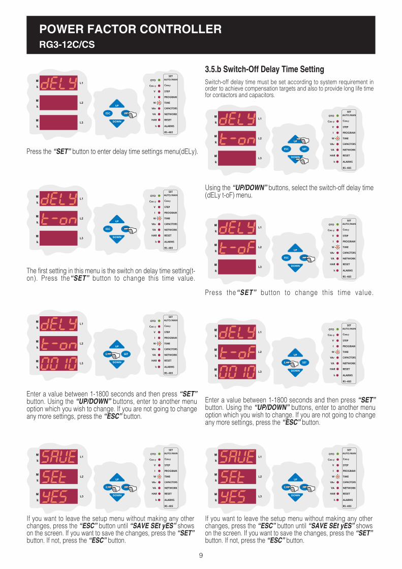
3.5.b Switch-Off Delay Time Setting
Press the �SET� button to enter delay time settings menu(dELy).
The first setting in this menu is the switch on delay time setting(t-on). Press the�SET� button to change this time value.
Enter a value between 1-1800 seconds and then press �SET�button. Using the �UP/DOWN� buttons, enter to another menuoption which you wish to change. If you are not going to changeany more settings, press the �ESC� button.
SAUE
If you want to leave the setup menu without making any otherchanges, press the �ESC� button until �SAVE SEt yES� showson the screen. If you want to save the changes, press the �SET�button. If not, press the �ESC� button.
Switch-off delay time must be set according to system requirement inorder to achieve compensation targets and also to provide long life timefor contactors and capacitors.
Using the �UP/DOWN� buttons, select the switch-off delay time(dELy t-oF) menu.
Press the�SET� button to change this t ime value.
SAUE
If you want to leave the setup menu without making any otherchanges, press the �ESC� button until �SAVE SEt yES� showson the screen. If you want to save the changes, press the �SET�button. If not, press the �ESC� button.
Enter a value between 1-1800 seconds and then press �SET�button. Using the �UP/DOWN� buttons, enter to another menuoption which you wish to change. If you are not going to changeany more settings, press the �ESC� button.
POWER FACTOR CONTROLLERRG3-12C/CS
10
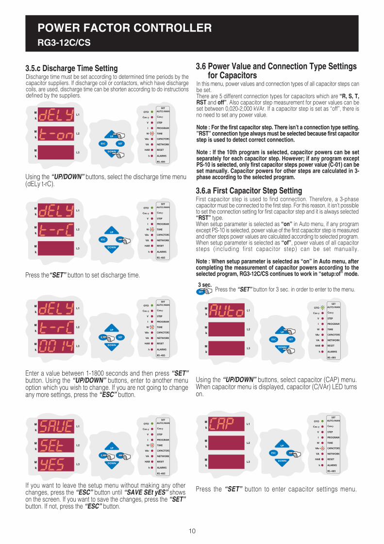
Discharge time must be set according to determined time periods by thecapacitor suppliers. If discharge coil or contactors, which have dischargecoils, are used, discharge time can be shorten according to do instructionsdefined by the suppliers.
3.5.c Discharge Time Setting
Using the �UP/DOWN� buttons, select the discharge time menu(dELy t-rC).
Press the�SET� button to set discharge time.
Enter a value between 1-1800 seconds and then press �SET�button. Using the �UP/DOWN� buttons, enter to another menuoption which you wish to change. If you are not going to changeany more settings, press the �ESC� button.
SAUE
If you want to leave the setup menu without making any otherchanges, press the �ESC� button until �SAVE SEt yES� showson the screen. If you want to save the changes, press the �SET�button. If not, press the �ESC� button.
3.6.a First Capacitor Step SettingFirst capacitor step is used to find connection. Therefore, a 3-phasecapacitor must be connected to the first step. For this reason, it isn�t possibleto set the connection setting for first capacitor step and it is always selected�RST� type.When setup parameter is selected as �on� in Auto menu, if any programexcept PS-10 is selected, power value of the first capacitor step is measuredand other steps power values are calculated according to selected program.When setup parameter is selected as �of�, power values of all capacitorsteps (including first capacitor step) can be set manually.
Note : When setup parameter is selected as �on� in Auto menu, aftercompleting the measurement of capacitor powers according to theselected program, RG3-12C/CS continues to work in �setup:of� mode.
In this menu, power values and connection types of all capacitor steps canbe set.There are 5 different connection types for capacitors which are �R, S, T,RST and off�. Also capacitor step measurement for power values can beset between 0,020-2,000 kVAr. If a capacitor step is set as �off�, there isno need to set any power value.
Note : For the first capacitor step. There isn�t a connection type setting.�RST� connection type always must be selected because first capacitorstep is used to detect correct connection.
Note : If the 10th program is selected, capacitor powers can be setseparately for each capacitor step. However; if any program exceptPS-10 is selected, only first capacitor steps power value (C-01) can beset manually. Capacitor powers for other steps are calculated in 3-phase according to the selected program.
3.6 Power Value and Connection Type Settings for Capacitors
Using the �UP/DOWN� buttons, select capacitor (CAP) menu.When capacitor menu is displayed, capacitor (C/VAr) LED turnson.
Press the �SET� button to enter capacitor settings menu.
Press the �SET� button for 3 sec. in order to enter to the menu.3 sec.

Enter the power value of the first capacitor step and then press the �SET�button. If you do not want to set another parameter, press the �ESC� button.
Note : If the 10th program is selected, capacitor powers can be setseparately for each capacitor step. However; if any program exceptPS-10 is selected, only first capacitor steps power value (C-01) can beset manually. Capacitor powers for other steps are calculated in 3-phase according to the selected program.
POWER FACTOR CONTROLLERRG3-12C/CS
11
Press the �SET� but ton to enter to the f i rs t capaci tor s tepsetting menu(C-01) which is the first menu under the capacitormenu option.
First capacitor step is used to find connection. Therefore, a 3-phasecapacitor must be connected to the first step. For this reason, it isn�tpossible to set the connection setting for first capacitor step and it isalways selected �RST� type and it can not be changed. Press the �SET�button to set power value of the first capacitor step.
SAUE
If you want to leave the setup menu without making any other changes,press the �ESC� button until �SAVE SEt yES� shows on the screen. Ifyou want to save the changes, press the �SET� button. If not, press the�ESC� button.
When PS-10 (Program 10) is selected, connection type and capacitor powervalue settings of all capacitor steps from the 2nd to the 12th can be set.When a program expect PS-10 is selected, only first capacitor steps settingcan be changed and other steps can not be set.
Using the �UP/DOWN� buttons, second capacitor steps connection typecan be set manually as connected to the �r�, �S�, �t� or �rSt� phase/phases.If this parameter is selected as �oFF�, capacitor step which is connectedto the second step will be disabled.
Note : After automatic calculation of the capacitors, if �oFF� is displayedin any step, it means that related capacitor could not be calculated, isdefected or there is no connected capacitors in the related step.
3.6.b Second Capacitor Step Setting
Using the �UP/DOWN� buttons, find the second capacitor step setting menu(C-02).
The first setting in the second capacitor step menu is the connectiontype. Press the �SET� but ton to select connect ion type.
2
Enter the power value of the second capacitor step and then press the�SET� button. If you do not want to set another parameter, press the �ESC�button.
P r e s s t h e � S E T � b u t t o n t o s e t s e c o n d c a p a c i t o r s t e p sp o w e r v a l u e .

POWER FACTOR CONTROLLERRG3-12C/CS
12
2
SAUE
If you want to leave the setup menu without making any other changes,press the �ESC� button until �SAVE SEt yES� shows on the screen. Ifyou want to save the changes, press the �SET� button. If not, press the�ESC� button.
Enter the power value of the second capacitor step and then press the�SET� button. If you do not want to set another parameter, press the �ESC�button.
CAP C-03In this menu, capacitor setting for third step are done.CAP C-04In this menu, capacitor setting for fourth step are done.CAP C-05In this menu, capacitor setting for fifth step are done.CAP C-06In this menu, capacitor setting for sixth step are done.CAP C-07In this menu, capacitor setting for seventh step are done.CAP C-08In this menu, capacitor setting for eighth step are done.CAP C-09In this menu, capacitor setting for nineth step are done.CAP C-10In this menu, capacitor setting for tenth step are done.CAP C-11In this menu, capacitor setting for eleventh step are done.CAP C-12In this menu, capacitor setting for twelveth step are done.
Above capacitor steps� settings are done just like second capacitor stepsetting (C-02).
In this menu, current transformer ratio can be set between 1-2000.For example : For a 150/5 current transformer, CT ratio must be set as30.
Note : Be aware that this value is entered as a ratio, not CT primaryor secondary value.
3.7.a Current Transformer Ratio Setting
To obtain accurate power values when calculating the capacitor steppowers, current and voltage transformer ratios must be entered correctly.If these ratios are entered incorrectly, the calculated capacitor step powerswill be incorrect. When these ratios aren�t entered, the device will set theseratios as �1� and capacitor step powers will be calculated according tothis setting.Current and voltage transformer ratios can be set separately.
Using the �UP/DOWN� buttons, find current and voltage transformer ratiomenu (trF). When this menu is selected, Transformer (VA/TRF) LED turnson.
Press the �SET� button to enter to the CT and VT ratio setting menu.
Enter CT ratio between 1-2000 and press the �SET� button. If you do not wantto set another parameter, press the �ESC� button.
SAUE
If you want to leave the setup menu without making any other changes,press the �ESC� button until �SAVE SEt yES� shows on the screen. Ifyou want to save the changes, press the �SET� button. If not, press the�ESC� button.
3.7 Current and Voltage Transformer Ratio Settings
Press the �SET� button for 3 sec. in order to enter to the menu.3 sec.
The first setting in the CT and VT ratio menu is the CT ratio menu.Press the �SET� button to set CT ratio.

POWER FACTOR CONTROLLERRG3-12C/CS
13
In this menu, voltage transformer ratio can be set between 1-2000.For example: For a 34,5 kV / 100 V transformer, VT ratio must be set as345.
Note : Be aware that this value is entered as a ratio, not VT primary orsecondary value.
3.7.b Voltage Transformer Ratio Setting
Using the �UP/DOWN� buttons, enter the voltage transformer ratio (Vtr)menu which is the second menu in CT and VT ratio settings.
Press the �SET� button to set VT ratio.
Enter VT ratio between 1-2000 and press the �SET� button. If you are goingto change another setting, enter to that setting menu using the �UP/DOWN�buttons. If you do not want to set another parameter, press the �ESC�button.
SAUE
If you want to leave the setup menu without making any other changes,press the �ESC� button until �SAVE SEt yES� shows on the screen. Ifyou want to save the changes, press the �SET� button. If not, press the�ESC� button.
3.7.c Reactive Energy Calculation Method SettingThree different methods exist for reactive energy calculation in RG3-12C/CS.Brief informations about these methods are explained in below table.Related values which must be entered in the menu are also indicated inthe table in order to select reactive power calculation methode for mechanicaland digital energymeters.
Using the �UP/DOWN� buttons, find the reactive energy calculation methodmenu(CALC).
Press the �SET� button to select the calculation method.
In order to select reactive energy calculation method (for mechanical anddigital energymeter), enter a value between 0-5 and press the �SET�button. If you are going to change another setting, enter to that setting menuusing the �UP/DOWN� buttons. If you do not want to set another parameter,press the �ESC� button.
SAUE
If you want to leave the setup menu without making any other changes,press the �ESC� button until �SAVE SEt yES� shows on the screen. Ifyou want to save the changes, press the �SET� button. If not, press the�ESC� button.
0
2
4
1
3
5
Description
It is the most preferred reactive power calculationmethod.
Total value of the multiplication of Vn and In values upto 19 th harmonics. This calculation method is mostlypreferred for network analysers.
SVn.In.sin(jn)n=1
¥
Reactive Energy(Q)
Digital Energymeter(Separately for each phase)
Mechanical Energymeter(Total sum of the three phases)
Rotate the voltagevector by 90° andmultiply with current
S2-P2S2-P2Power Triangle Method : In this method; Q =
(Q : Reactive power, P : Active power, S : Apparent power)It is a less preferred method compared to the other methods.

POWER FACTOR CONTROLLERRG3-12C/CS
14
In this menu; alarms and ratios(reactive/active ratios) are reset.
The alarms which occur when the device operates are reset in this menu.To reset the alarms, �yES� option must be selected.
Note : When an alarm occurs, the alarm relay switches on and therelated alarms LED turns on and the alarm code is displayed. Even ifalarm conditions disappear, the alarm relay will stay switched on. Byusing the reset menu, alarms are reset and alarm relay is switched off.If alarm conditions still exist, even if alarms are reset in the �reset�menu, alarm relay switches on again. If alarm conditions disappeared,alarm relay continues to its normal operation.
3.8.a Alarm Reset Setting
3.8 Reset Settings
Using the �UP/DOWN� buttons, find the reset menu option(rESEt). Whenreset menu is selected, reset LED turns on.
Press the �SET� button to enter reset(rESEt) setting options.
Press the �SET� button to set the alarm(ALAr) setting which is the firstsetting in the reset(rESEt) menu.
Using the �UP/DOWN� buttons, select �yES� to delete alarm values or�no� to cancel the delete process and then press �SET� button.
3.8.b Reactive/Active Ratio Reset SettingReactive/active ratio, which is calculated by the device, is reset in thismenu.
SAUE
If you want to leave the setup menu without making any other changes,press the �ESC� button until �SAVE SEt yES� shows on the screen. Ifyou want to save the changes, press the �SET� button. If not, press the�ESC� button.
Using the �UP/DOWN� buttons, find �reactive/active ratio reset� menu(rAtE)which is the second setting in the reset(rESEt) menu.
Press the �SET� button to enter the reactive/active ratio reset settings.
Using the �UP/DOWN� buttons, select �yES� to delete reactive/active ratioor �no� to cancel the delete process and then press �SET� button.
Press the �SET� button for 3 sec. in order to enter to the menu.3 sec.

POWER FACTOR CONTROLLERRG3-12C/CS
15
If one or more of measured phase voltage values exceed preset voltagevalue, an alarm occurs at the end of the adjusted delay time. Delay timecan be set between 0-999.9 seconds.
3.9.a.b Overvoltage Delay Time Setting
In this menu, alarm values for overvoltage, reactive/active ratio,*temperature and THD can be set saparately.Device has 2 relay outputs in addition to capacitor step relays which arealarm relay and *fan relay.If any of the above mentioned alarm conditions (except temperature)occurs, alarm relay switches on and the related error LED and alarm LED( ) light(Refer to �errors� section for details).Also, related error code is displayed on the display(Refer to page 30 foralarm codes).
* Optional
In this menu, the limit value for the overvoltage alarm is set. This value isused for all three phases. If any phase value exceeds the set value andthe alarm condition still exists even after the entered delay time is over,alarm relay switches on and the overvoltage LED(V>) turns on.
3.9.a Overvoltage Alarm Setting
3.9 Alarm Settings
In this menu, overvoltage value is set between 0-300 V (for Vtr=1).If this value is set as �0�, this function is disabled.
3.9.a.a Overvoltage Setting
SAUE
If you want to leave the setup menu without making any other changes,press the �ESC� button until �SAVE SEt yES� shows on the screen. Ifyou want to save the changes, press the �SET� button. If not, press the�ESC� button.
Using the �UP/DOWN� buttons, find Alarm(ALr) menu. When Alarm menuis selected, alarm LED turns on.
The first setting in the alarm menu(ALr) is the voltage(UoLt). Press the�SET� button to enter the overvoltage settings menu.
Overvoltage value (SP-H), delay time (dELy) and overvoltage step (StEP)parameters can be set in this menu. In order to set these parameters,press the �SET� button.
Press the �SET� button to set the overvoltage value(SP-H).
Enter the overvoltage value between 0-300 V. If you are going to changeanother setting, return to the menu by pressing the �SET� button. If you donot want to set another parameter, press the �ESC� button.
Note : If over voltage value is set as �0�, this function is disabled.
Press the �DOWN� button to select the over voltage delay time (dELy)menu.
Press the �SET� button for 3 sec. in order to enter to the menu.3 sec.

POWER FACTOR CONTROLLERRG3-12C/CS
16
3.9.a.c Switch On or Switch Off Setting of CapacitorSteps for Overvoltage Alarm Setting
If reactive/active energy ratio exceeds the preset value, an alarm occurs.This ratio can be set for inductive/active and capacitive/active separatelybetween 0-99.9 %. If this value is set as �0�, this function is disabled.
3.9.b Reactive / Active Ratio Setting
In order to provide accurate compensation, the upper limit value ofcapacitive/active ratio is entered in this menu. This value can be setbetween 0-99.9 %. If the capacitive/active ratio of the network exceedsthe preset value, an alarm occurs. If this value is set as �0�, this functionis disabled.
3.9.b.a Capacitive Ratio Setting
The second setting in the voltage menu(UoLt) is the overvoltage delaytime(dELy). Press the �SET� button to enter the overvoltage delay timesetting menu.
SAUE
If you want to leave the setup menu without making any other changes,press the �ESC� button until �SAVE SEt yES� shows on the screen. Ifyou want to save the changes, press the �SET� button. If not, press the�ESC� button.
Enter the over voltage delay time between 0-999.9 seconds. If you aregoing to change another setting, return to the menu by pressing the �SET�button. If you do not want to set another parameter, press the �ESC�button.
The third setting in the voltage menu(UoLt) is the overvoltage stepsetting(StEP). Press the �SET� button to enter the overvoltage step settingmenu.
Using the �UP/DOWN� buttons, select �on� or �of� option and press the�SET� button. If you are going to change another setting, return to the menuby pressing the �SET� button. If you do not want to set another parameter,press the �ESC� button.
SAUE
If you want to leave the setup menu without making any other changes,press the �ESC� button until �SAVE SEt yES� shows on the screen. Ifyou want to save the changes, press the �SET� button. If not, press the�ESC� button.
Press the �DOWN� button in order to switch from overvoltage menu to theovervoltage step menu(StEP).
Using the �UP/DOWN� buttons, find Alarm (Alr) menu. When �Alarm�menu is selected, alarm LED turns on.
Press the �SET� button for 3 sec. in order to enter to the menu.3 sec.
In order to protect the capacitors from overvoltage, when an overvoltagealarm occurs, capacitor steps� switch on or switch off settings are donein this menu.If �on� is selected: When overvoltage error occurs, capacitor stepsstay switched on.If �off� is selected: When overvoltage error occurs, capacitor stepsstay switched off.

POWER FACTOR CONTROLLERRG3-12C/CS
17
3.9.b.b Inductive Ratio Setting
Press the �SET� button to enter the alarm(ALr) settings menu.
Using the �UP/DOWN� buttons, find reactive/active ratio (rAtE) menu.
The second setting in the alarm menu(ALr) is the reactive/active energyratio menu(rAtE). From this menu, the upper limit value of thecapacitive/active and inductive/active ratios can be set. Press the �SET�button to set these values.
Press the �SET� button to set the capacitive/active ratio.
Enter the capacitive/active ratio between 0-99.9 % and press the �SET�button. If you are going to change another setting, return to the menu bypressing the �SET� button. If you do not want to set another parameter,press the �ESC� button.
SAUE
If you want to leave the setup menu without making any other changes,press the �ESC� button until �SAVE SEt yES� shows on the screen. Ifyou want to save the changes, press the �SET� button. If not, press the�ESC� button.
In order to provide accurate compensation, the upper limit value ofinductive/active ratio is entered in this menu. This value can be set between0-99.9 %. If the inductive/active ratio of the network exceeds the presetvalue, an alarm occurs. If this value is set as �0�, this function is disabled.
When �Alr rAtE CAP� is displayed on the display, find �rAtE Ind� menuby using �UP/DOWN� buttons.
Enter the inductive/active ratio between 0-99.9 % and press the �SET�button. If you are going to change another setting, return to the menu bypressing the �SET� button. If you do not want to set another parameter,press the �ESC� button.
Press the �SET� button to set the inductive/active ratio.

POWER FACTOR CONTROLLERRG3-12C/CS
18
In this menu; the upper temperature limit, which activates the overheatingprotection, is programmed between �00.0-99.9 °C�(Refer to �TechnicalFeatures� section for measurable ranges).
3.9.c.a Programming the Upper Limit of Temperature Alarm
Note : Temperature measurement feature is optional for RG3-12CS.In order to protect the capacitors from overheating, upper (HEAt SP-H) andlower (HEAt SP-L) limits between �00.0-99.9 °C� and step protection (HEAtStEP) are all set in this menu. If the temperature exceeds the upper limit,which is programmed in the device, for 10 seconds; RG3-12C/CS givesan alarm signal (Erro r-10) and switches off or does nothing for the capacitorsteps according to selected capacitor step setting(HEAt STEP). After thetemperature stays under the lower limit value for 10 seconds, the alarmstate disappears.
3.9.c Temperature Alarm Settings
SAUE
If you want to leave the setup menu without making any other changes,press the �ESC� button until �SAVE SEt yES� shows on the screen. Ifyou want to save the changes, press the �SET� button. If not, press the�ESC� button.
Press the �SET� button to enter the alarm(ALr) sett ings.
Using the �UP/DOWN� buttons, find temperature alarm menu(HEAT) whichis the second setting in the alarm menu.
Press the �SET� button to enter the upper limit of the temperaturevalue(SP-H).
Press the �SET� button to select the �SP-H� menu in which the upper andlower limits for the temperature alarm to activate or deactivate the alarmrelay is programmed.
Enter a value between �00.0-99.9 °C� and press the �SET� button. If youare going to change another setting, return to the menu by pressing the�SET� button. If you do not want to set another parameter, press the �ESC�button.
SAUE
If you want to leave the setup menu without making any other changes,press the �ESC� button until �SAVE SEt yES� shows on the screen. Ifyou want to save the changes, press the �SET� button. If not, press the�ESC� button.
Using the �UP/DOWN� buttons, find the alarm menu(ALr). When �Alarm�menu is selected, alarm LED turns on.
Press the �SET� button for 3 sec. in order to enter to themenu.
3 sec.
POWER FACTOR CONTROLLERRG3-12C/CS
19
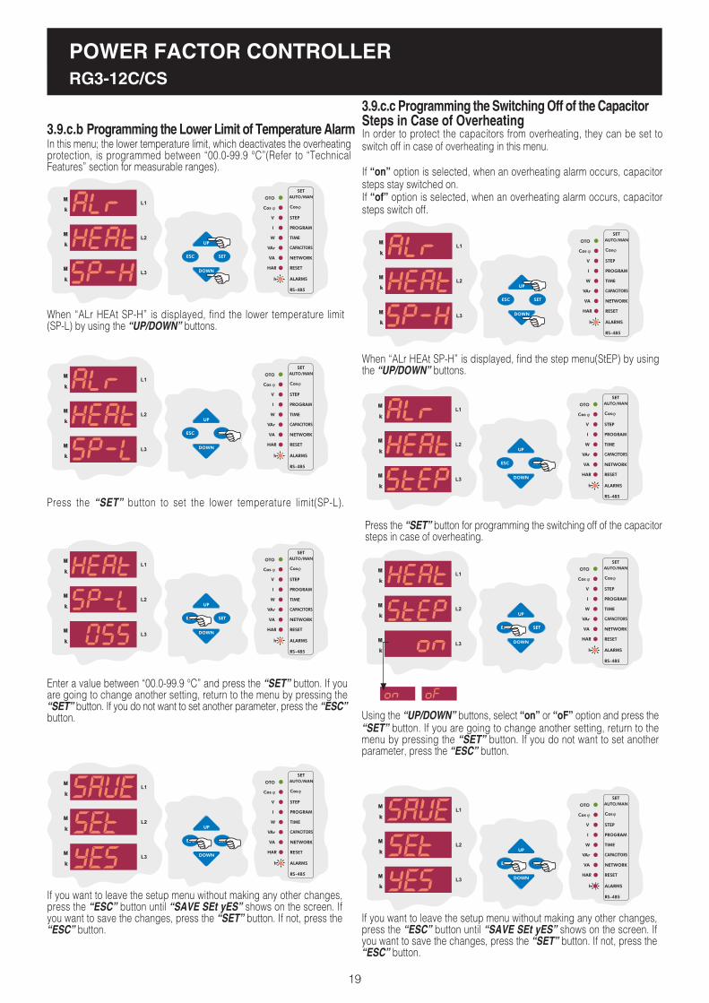
3.9.c.b Programming the Lower Limit of Temperature Alarm
3.9.c.c Programming the Switching Off of the CapacitorSteps in Case of OverheatingIn order to protect the capacitors from overheating, they can be set toswitch off in case of overheating in this menu.
If �on� option is selected, when an overheating alarm occurs, capacitorsteps stay switched on.If �of� option is selected, when an overheating alarm occurs, capacitorsteps switch off.
In this menu; the lower temperature limit, which deactivates the overheatingprotection, is programmed between �00.0-99.9 °C�(Refer to �TechnicalFeatures� section for measurable ranges).
When �ALr HEAt SP-H� is displayed, find the lower temperature limit(SP-L) by using the �UP/DOWN� buttons.
Press the �SET� button to set the lower temperature limit(SP-L).
Enter a value between �00.0-99.9 °C� and press the �SET� button. If youare going to change another setting, return to the menu by pressing the�SET� button. If you do not want to set another parameter, press the �ESC�button.
SAUE
If you want to leave the setup menu without making any other changes,press the �ESC� button until �SAVE SEt yES� shows on the screen. Ifyou want to save the changes, press the �SET� button. If not, press the�ESC� button.
When �ALr HEAt SP-H� is displayed, find the step menu(StEP) by usingthe �UP/DOWN� buttons.
Press the �SET� button for programming the switching off of the capacitorsteps in case of overheating.
Using the �UP/DOWN� buttons, select �on� or �oF� option and press the�SET� button. If you are going to change another setting, return to themenu by pressing the �SET� button. If you do not want to set anotherparameter, press the �ESC� button.
SAUE
If you want to leave the setup menu without making any other changes,press the �ESC� button until �SAVE SEt yES� shows on the screen. Ifyou want to save the changes, press the �SET� button. If not, press the�ESC� button.

POWER FACTOR CONTROLLERRG3-12C/CS
20
If total voltage harmonýc value exceeds preset value and does not turn tonormal level during the delay time(dELy) which is entered in this menu, analarm occurs.
3.9.d.b Harmonic Alarm Delay Time Setting
If total harmonic value of measured voltages exceeds the value which isenterd from this menu and does not return to normal level during the entereddelay time(dELy), alarm relay switches on and harmonic LED( ) turns on.
3.9.d Harmonic Setting
The upper limit for the overvoltage harmonic value to set the harmonicalarm is set in this menu.
3.9.d.a Overvoltage Harmonic Setting
Using the �UP/DOWN� buttons, find the alarm menu(ALr). When alarmmenu is selected, alarm LED turns on.
Press the �SET� button to enter the alarm(ALr) sett ings.
Using the �UP/DOWN� buttons, find over voltage harmonic menu(tHd)which is the fourth setting in the alarm menu.
In this menu, over voltage harmonic value(tHdV), delay time(dELy)and switching off of the capacitor steps(StEP) parameters are set. In orderto set these parametesers, press the �SET� button.
SAUE
If you want to leave the setup menu without making any other changes,press the �ESC� button until �SAVE SEt yES� shows on the screen. Ifyou want to save the changes, press the �SET� button. If not, press the�ESC� button.
Press the �SET� button to set overvoltage harmonic(thdV) value.
Enter the overvoltage harmonic value between 0-99 % and press the�SET� button.
Using the �UP/DOWN� buttons, find the delay time(dELy) menu.
Press the �SET� button for delay time menu(dELy) which is the secondsetting in the harmonic menu.
Press the �SET� button for 3 sec. in order to enter to themenu.
3 sec.
If you want to leave the setup menu without making any other changes,press the �ESC� button until �SAVE SEt yES� shows on the screen. Ifyou want to save the changes, press the �SET� button. If not, press the�ESC� button.
POWER FACTOR CONTROLLERRG3-12C/CS
21
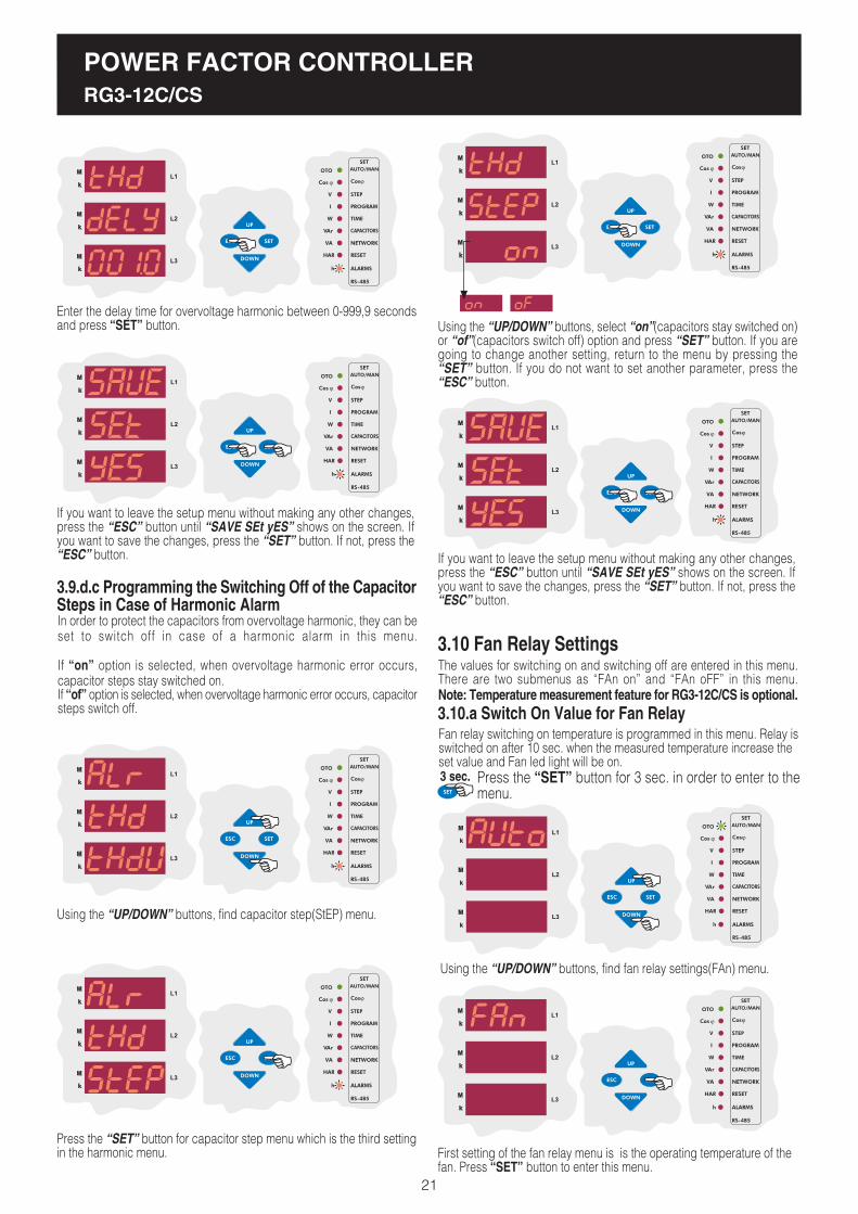
3.9.d.c Programming the Switching Off of the CapacitorSteps in Case of Harmonic AlarmIn order to protect the capacitors from overvoltage harmonic, they can beset to switch off in case of a harmonic alarm in this menu.
If �on� option is selected, when overvoltage harmonic error occurs,capacitor steps stay switched on.If �of� option is selected, when overvoltage harmonic error occurs, capacitorsteps switch off.
SAUE
If you want to leave the setup menu without making any other changes,press the �ESC� button until �SAVE SEt yES� shows on the screen. Ifyou want to save the changes, press the �SET� button. If not, press the�ESC� button.
SAUE
Enter the delay time for overvoltage harmonic between 0-999,9 secondsand press �SET� button.
Using the �UP/DOWN� buttons, find capacitor step(StEP) menu.
Press the �SET� button for capacitor step menu which is the third settingin the harmonic menu.
Using the �UP/DOWN� buttons, select �on�(capacitors stay switched on)or �of�(capacitors switch off) option and press �SET� button. If you aregoing to change another setting, return to the menu by pressing the�SET� button. If you do not want to set another parameter, press the�ESC� button.
The values for switching on and switching off are entered in this menu.There are two submenus as �FAn on� and �FAn oFF� in this menu.Note: Temperature measurement feature for RG3-12C/CS is optional.
3.10 Fan Relay Settings
3.10.a Switch On Value for Fan RelayFan relay switching on temperature is programmed in this menu. Relay isswitched on after 10 sec. when the measured temperature increase theset value and Fan led light will be on.
First setting of the fan relay menu is is the operating temperature of thefan. Press �SET� button to enter this menu.
Press the �SET� button for 3 sec. in order to enter to themenu.
3 sec.
Using the �UP/DOWN� buttons, find fan relay settings(FAn) menu.

POWER FACTOR CONTROLLERRG3-12C/CS
22
Press the �SET� button to enter the fan switch on temperature value.
Enter the temperature alarm between �00.0-99.8� °C and press the �SET�button. If you are going to change another setting, return to the menu bypressing the �SET� button. If you do not want to set another parameter,press the �ESC� button.
SAUE
If you want to leave the setup menu without making any other changes,press the �ESC� button until �SAVE SEt yES� shows on the screen. Ifyou want to save the changes, press the �SET� button. If not, press the�ESC� button.
3.10.b Switch Off Value for Fan RelayFan relay switching off temperature is programmed in this menu.
The first parameter in the Fan menu(FAn) is the operating temperature ofthe fan. Press �SET� button to enter the operating temperature settings.
Press the �SET� button to program the switch off value for thefan relay.
Press �SET� button to enter the temperature alarm between�00.0-99.8� °C(A higher value than �FAn on� value can not beprogrammed). If you are going to change another setting, returnto the menu by pressing the �SET� button. If you do not want toset another parameter, press the �ESC� button.
SAUE
If you want to leave the setup menu without making any other changes,press the �ESC� button until �SAVE SEt yES� shows on the screen. Ifyou want to save the changes, press the �SET� button. If not, press the�ESC� button.
Using the �UP/DOWN� buttons, find �FAn oFF� menu which is the secondsetting in the fan relay menu.
POWER FACTOR CONTROLLERRG3-12C/CS
3.11.a Entering the Energy Values
Using the �UP/DOWN� buttons, find the energy menu(EnErgy).
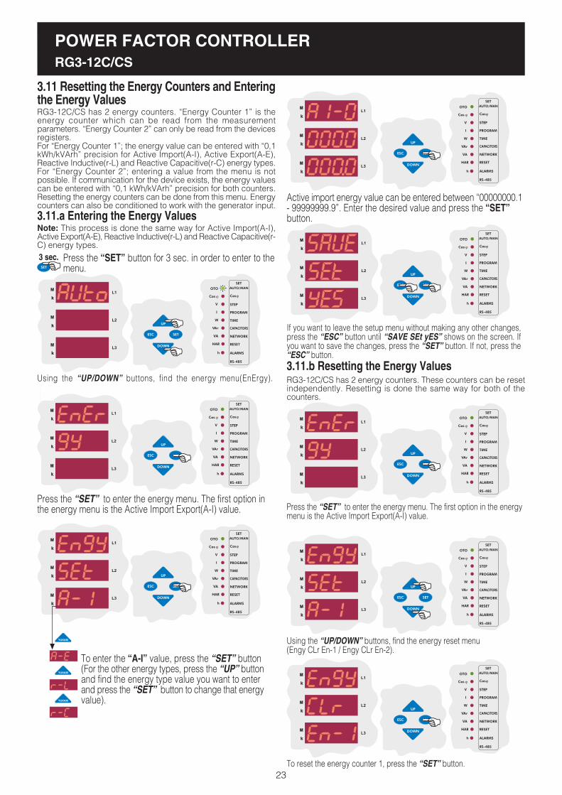
Press the �SET� to enter the energy menu. The first option inthe energy menu is the Active Import Export(A-I) value.
To enter the �A-I� value, press the �SET� button(For the other energy types, press the �UP� buttonand find the energy type value you want to enterand press the �SET� button to change that energyvalue).
RG3-12C/CS has 2 energy counters. �Energy Counter 1� is theenergy counter which can be read from the measurementparameters. �Energy Counter 2� can only be read from the devicesregisters.For �Energy Counter 1�; the energy value can be entered with �0,1kWh/kVArh� precision for Active Import(A-I), Active Export(A-E),Reactive Inductive(r-L) and Reactive Capacitive(r-C) energy types.For �Energy Counter 2�; entering a value from the menu is notpossible. If communication for the device exists, the energy valuescan be entered with �0,1 kWh/kVArh� precision for both counters.Resetting the energy counters can be done from this menu. Energycounters can also be conditioned to work with the generator input.
3.11 Resetting the Energy Counters and Enteringthe Energy Values
Note: This process is done the same way for Active Import(A-I),Active Export(A-E), Reactive Inductive(r-L) and Reactive Capacitive(r-C) energy types.
Active import energy value can be entered between �00000000.1- 99999999.9�. Enter the desired value and press the �SET�button.
SAUE
If you want to leave the setup menu without making any other changes,press the �ESC� button until �SAVE SEt yES� shows on the screen. Ifyou want to save the changes, press the �SET� button. If not, press the�ESC� button.
3.11.b Resetting the Energy ValuesRG3-12C/CS has 2 energy counters. These counters can be resetindependently. Resetting is done the same way for both of thecounters.
Press the �SET� to enter the energy menu. The first option in the energymenu is the Active Import Export(A-I) value.
Using the �UP/DOWN� buttons, find the energy reset menu(Engy CLr En-1 / Engy CLr En-2).
To reset the energy counter 1, press the �SET� button.
Press the �SET� button for 3 sec. in order to enter to themenu.
3 sec.
23
POWER FACTOR CONTROLLERRG3-12C/CS
RG3-12C/CS has MODBUS-RTU communication protocol. All measuredparameters can be saved into computer�s memory via appropriate software.Additionally, all necessary configurations also can be set via software.
NOTE: Computer communication feature is only available forRG3-12CS model.
By changing the device address setting, communication up to 247 devicescan be achieved.
3.11.a Device Address Setting
3.11 Computer Communication Settings (RS-485)
Using the �UP/DOWN� buttons, find computer communication menu(RS-485).
Press the �SET� button for 3 sec. in order to enter to the menu.3 sec.
24
Using the �UP/DOWN� buttons, select �yES� to reset the energy countersor select �no� to cancel the resetting and press the �SET� button.
SAUE
If you want to leave the setup menu without making any other changes,press the �ESC� button until �SAVE SEt yES� shows on the screen. Ifyou want to save the changes, press the �SET� button. If not, press the�ESC� button.
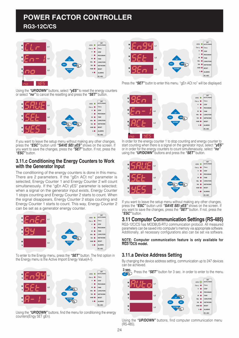
3.11.c Conditioning the Energy Counters to Workwith the Generator InputThe conditioning of the energy counters is done in this menu.There are 2 parameters. If the �gEn ACt no� parameter isselected, Energy Counter 1 and Energy Counter 2 will countsimultaneously. If the �gEn ACt yES� parameter is selected;when a signal on the generator input exists, Energy Counter1 stops counting and Energy Counter 2 starts to count. Whenthe signal disappears, Energy Counter 2 stops counting andEnergy Counter 1 starts to count. This way, Energy Counter 2can be set as a generator energy counter.
To enter to the Energy menu, press the �SET� button. The first option inthe Energy menu is the Active Import Energy Value(A-I).
Using the �UP/DOWN� buttons, find the menu for conditioning the energycounters(Engy SET gEn).
Press the �SET� buttýn to enter this menu. �gEn ACt no� will be displayed.
In order for the energy counter 1 to stop counting and energy counter tostart counting when there is a signal on the generator input, select �yES�or in order for the energy counters to count simultenaously, select �no�using the �UP/DOWN� buttons and press the �SET� button.
SAUE
If you want to leave the setup menu without making any other changes,press the �ESC� button until �SAVE SEt yES� shows on the screen. Ifyou want to save the changes, press the �SET� button. If not, press the�ESC� button.
POWER FACTOR CONTROLLERRG3-12C/CS
25
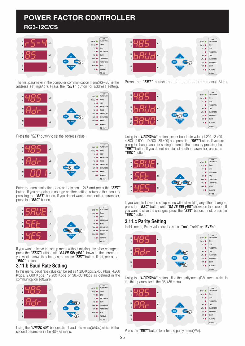
The first parameter in the computer communication menu(RS-485) is theaddress setting(Adr). Prass the �SET� button for address setting.
Press the �SET� button to set the address value.
Enter the communication address between 1-247 and press the �SET�button. If you are going to change another setting, return to the menu bypressing the �SET� button. If you do not want to set another parameter,press the �ESC� button.
In this menu, baud rate value can be set as 1.200 Kbps, 2.400 Kbps, 4.800Kbps, 9.600 Kbps, 19.200 Kbps or 38.400 Kbps as defined in thecommunication software.
3.11.b Baud Rate Setting
Using the �UP/DOWN� buttons, enter baud rate value (1.200 - 2.400 -4.800 - 9.600 - 19.200 - 38.400) and press the �SET� button. If you aregoing to change another setting, return to the menu by pressing the�SET� button. If you do not want to set another parameter, press the�ESC� button.
In this menu, Parity value can be set as �no�, �odd� or �EVEn�.
3.11.c Parity Setting
SAUE
If you want to leave the setup menu without making any other changes,press the �ESC� button until �SAVE SEt yES� shows on the screen. Ifyou want to save the changes, press the �SET� button. If not, press the�ESC� button.
Using the �UP/DOWN� buttons, find baud rate menu(bAUd) which is thesecond parameter in the RS-485 menu.
Press the �SET� button to enter the baud rate menu(bAUd).
SAUE
If you want to leave the setup menu without making any other changes,press the �ESC� button until �SAVE SEt yES� shows on the screen. Ifyou want to save the changes, press the �SET� button. If not, press the�ESC� button.
Using the �UP/DOWN� buttons, find the parity menu(PAr) menu which isthe third parameter in the RS-485 menu.
Press the �SET� button to enter the parity menu(PAr).

POWER FACTOR CONTROLLERRG3-12C/CS
26
The first parameter in the password menu is the parameter activationmenu(Pin ACt). According to this setting, password for the device menucan be set �inactive� or �active�. Press the �SET� button to enter thismenu.
SAUE
If you want to leave the setup menu without making any other changes,press the �ESC� button until �SAVE SEt yES� shows on the screen. Ifyou want to save the changes, press the �SET� button. If not, press the�ESC� button.
If you did not activate the password before, enter the pin code as �1234�.If you changed the password before, enter that password. Press �SET�button to change the password activation setting.
Note: While entering the pin code, the blinking digit represents the digitwhich will be set. Press the �UP/DOWN� buttons to increase/decreasethe value of the related digit. Press �SET� button to set the next digit orpress �ESC� button to set previous digit.
Using the �UP/DOWN� buttons, select the �Pin ACt� as �on� or �of� andthen press the �SET� button. If you are going to change another setting,return to the menu by pressing the �SET� button. If you do not want toset another parameter, press the �ESC� button.
In this menu, user password is activated. When the password is activated,a pin code is always required before entering to the menu.
User password can be changed and activated in this menu. When thepassword is activated, a pin code is always required before entering tothe menu.Thus, user password prevents any change to the settings of the deviceby unauthorized people. For this reason, a pin code with 4 digits must beset and then it must be activated.
Note: Factory default value for pin code is �1234� and it is not activated.
3.12 Password Activation and Change Settings
3.12.a Pin Activation
Using the �UP/DOWN� buttons, find �Pin� menu.
Press �SET� button to enter the password menu.
Using the �UP/DOWN� buttons, select a parity option and press the �SET�button. If you are going to change another setting, return to the menu bypressing the �SET� button. If you do not want to set another parameter,press the �ESC� button.
SAUE
If you want to leave the setup menu without making any other changes,press the �ESC� button until �SAVE SEt yES� shows on the screen. Ifyou want to save the changes, press the �SET� button. If not, press the�ESC� button.
Press the �SET� button for 3 sec. in order to enter to the menu.3 sec.
In this menu, user password is changed. In order to change the password,old password and new password (x2 times) must be entered.
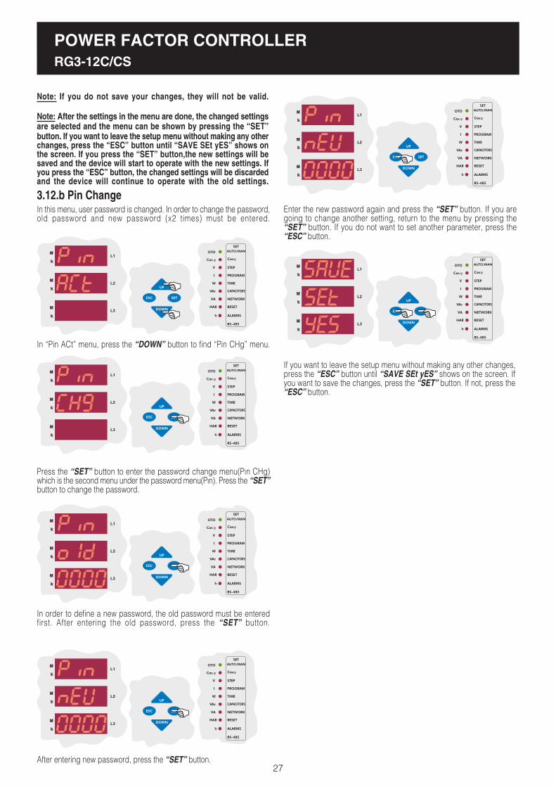
3.12.b Pin Change
In order to define a new password, the old password must be enteredfirst. After entering the old password, press the �SET� button.
In �Pin ACt� menu, press the �DOWN� button to find �Pin CHg� menu.
Press the �SET� button to enter the password change menu(Pýn CHg)which is the second menu under the password menu(Pýn). Press the �SET�button to change the password.
After entering new password, press the �SET� button.
Enter the new password again and press the �SET� button. If you aregoing to change another setting, return to the menu by pressing the�SET� button. If you do not want to set another parameter, press the�ESC� button.
SAUE
If you want to leave the setup menu without making any other changes,press the �ESC� button until �SAVE SEt yES� shows on the screen. Ifyou want to save the changes, press the �SET� button. If not, press the�ESC� button.
Note: If you do not save your changes, they will not be valid.
Note: After the settings in the menu are done, the changed settingsare selected and the menu can be shown by pressing the �SET�button. If you want to leave the setup menu without making any otherchanges, press the �ESC� button until �SAVE SEt yES� shows onthe screen. If you press the �SET� button,the new settings will besaved and the device will start to operate with the new settings. Ifyou press the �ESC� button, the changed settings will be discardedand the device will continue to operate with the old settings.
POWER FACTOR CONTROLLERRG3-12C/CS
27

In the �Instantaneous Values� menu, below network parameters can beobserved by using the �UP�, �DOWN� and �SET� buttons.
4. DISPLAYING OF INSTANTANEOUS VALUES
By pressing the �ESC� button repeatedly in any menu, �InstantaneousValues� menu can be displayed.This is the main menu of RG3-12C/CS. If you wait without pressing thebuttons in any menu, �Instantaneous Values� menu ýs displayedautomatically.When RG3-12C/CS is energised for the first time, �Instantaneous Values�menu is displayed.
CosjVoltages
When the device is energised, Cosj values of the 3-phases aredisplayed. A negative (-) sign indicates that the phase is capacitiveand a positive (+) sign indicates that the phase is inductive. As youcan see in the example below; Cosj value of the first phase iscapacitive, Cosj value of the the second and third phases areinductive.While observing cosj values, if �SET� button is pressed(HAR LED lights), harmonic values can be observed up to 19th(odd-numbered) harmonics.
When Cosj values are displayed, if �DOWN� button is pressed, TotalInductive Cosj and Total Capacitive Cosj values are observed. As youcan see in the example below, total inductive Cosj value is displayed onthe first display and total capacitive cosj value is displayed on the thirddisplay.
In the measurement mode, phase-neutral voltages can be displayed byusing �UP/DOWN� buttons when V LED lights. When phase voltages aredisplayed, if �SET� button is pressed (HAR LED lights), harmonic valuesup to 19th harmonic(odd-numbered) can be observed.
Cosj and HAR LEDs on the display indicate that the displayed valuesare harmonic values of the related cosj. By pressing the �SET� buttonrepeatedly, odd-numbered harmonic values up to 19th harmonic can beobserved.
V and HAR LEDs on the display indicate that displayed values are voltageharmonic values. By pressing the �SET� button repeatedly, THD and odd-numbered harmonic values up to 19th harmonic can be observed as %.
Currents
SPowers
Cosj
Energies
Active (W)
THD%I
-
-
Voltage
Apparent (VA)
SCosj
THD%V
-
-
-
-
-
-
L
N Reactive (VAr)
Temperature
-
-
POWER FACTOR CONTROLLERRG3-12C/CS
28
-.912
0.973
0.945
Total Cosj
1.000
-.947
225.5
228.7
223.4
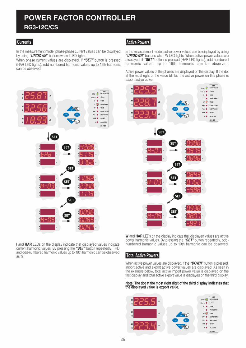
Active Powers
Total Active PowersWhen active power values are displayed, if the �DOWN� button is pressed,import active and export active power values are displayed. As seen inthe example below, total active import power value is displayed on thefirst display and total active export value is displayed on the third display.
Note: The dot at the most right digit of the third display indicates thatthe displayed value is export value.
W and HAR LEDs on the display indicate that displayed values are activepower harmonic values. By pressing the �SET� button repeatedly, odd-numbered harmonic values up to 19th harmonic can be observed.
In the measurement mode, phase-phase current values can be displayedby using �UP/DOWN� buttons when I LED lights.When phase current values are displayed, if �SET� button is pressed(HAR LED lights), odd-numbered harmonic values up to 19th harmoniccan be observed.
In the measurement mode, active power values can be displayed by using�UP/DOWN� buttons when W LED lights. When active power values aredisplayed, if �SET� button is pressed (HAR LED lights), odd-numberedharmonic values up to 19th harmonic can be observed.
Active power values of the phases are displayed on the display. If the dotat the most right of the value blinks, the active power on this phase isexport active power.
Currents
I and HAR LEDs on the display indicate that displayed values indicatecurrent harmonic values. By pressing the �SET� button repeatedly, THDand odd-numbered harmonic values up to 19th harmonic can be observedas %.
25.87
32.56
18.93
225.5
228.7
223.4
POWER FACTOR CONTROLLERRG3-12C/CS
29

Reactive Powers
Total Reactive Powers
VAr and HAR LEDs on the display represent that displayed values indicateharmonic values of the reactive powers. By pressing the �SET� buttonrepeatedly, odd-numbered harmonic values up to 19th harmonic can beobserved.
VA and HAR LEDs on the display indicate that displayed values areharmonic values of the apparent powers. By pressing �SET� buttonrepeatedly, odd-numbered harmonic values up to 19th harmonic can beobserved.
In the measurement mode, reactive power values are displayed by using�UP/DOWN� buttons when VAr LED lights. When reactive power valuesare displayed, if �SET� button is pressed (HAR LED lights), odd-numberedharmonic values up to 19th harmonic can be observed.
When active power values are displayed, if the �DOWN� button is pressed,inductive reactive and capacitive reactive power values are observed.As seen in the example below, total reactive inductive power value isdisplayed on the first display and total reactive capacitive power value isdisplayed on the third display.
Note : The dot at the most right digit of the third display indicates thatthe displayed value is capacitive reactive power.
225.5
228.7
223.4
225.5
223.4.
Apparent PowersIn the measurement mode, apparent power values are displayed by usingthe �UP/DOWN� buttons when VA LED lights. When apparent powervalues are displayed, if the �SET� button is pressed (HAR led lights), odd-numbered harmonic values up to 19th harmonic can be observed.
225.5
228.7
223.4
When apparent power values are displayed, if the �DOWN� button ispressed, total apparent power is displayed on the second display.
Total Apparent Powers
228.7
POWER FACTOR CONTROLLERRG3-12C/CS
30
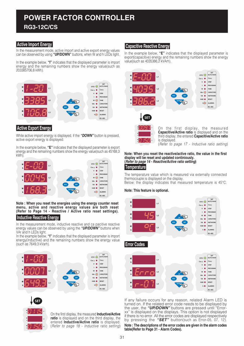
Note : When you reset the energies using the energy counter resetmenu, active and reactive energy values are both reset(Refer to Page 14 - Reactive / Active ratio reset settings).
Capacitive Reactive Energy
Temperature
On the first display, the measured Inductive/Activeratio is displayed and on the third display, theentered Inductive/Active ratio is displayed.(Refer to page 18 - Inductive ratio setting)
In the example below, �E� indicates that the displayed parameter isexport(capacitive) energy and the remaining numbers show the energyvalue(such as 4035386,2 kVArh).
The temperature value which is measured via externally connectedthermocouple is displayed on the display.Below; the display indicates that measured temperature is 45°C.
Note: This feature is optional.
On the f i r s t d i sp lay , t he measuredCapacitive/Active ratio is displayed and on thethird display, the entered Capacitive/Active ratiois displayed.(Refer to page 17 - Inductive ratio setting)
Note: When you reset the reactive/active ratio, the value in the firstdisplay will be reset and updated continiously.(Refer to page 14 - Reactive/Active ratio setting)
In the measurement mode, active import and active export energy valuescan be observed by using �UP/DOWN� buttons, when W and h LEDs light.
In the example below, �I� indicates that the displayed parameter is importenergy and the remaining numbers show the energy value(such as203385706,8 kWh).
While active import energy is displayed, if the �DOWN� button is pressed,active export energy is displayed.
In the example below, �E� indicates that the displayed parameter is exportenergy and the remaining numbers show the energy value(such as 45168,3kWh).
In the measurement mode, inductive reactive and ca pacitive reactiveenergy values can be observed by using the �UP/DOWN� buttons whenVAr and h LEDs light.In the example below, �I� indicates that the displayed parameter is importenergy(inductive) and the remaining numbers show the energy value(such as 7649,3 kVarh). Error Codes
Note : The descriptions of the error codes are given in the alarm codestable(Refer to Page 31 - Alarm Codes).
POWER FACTOR CONTROLLERRG3-12C/CS
Active Import Energy
1-20
3385
706.8
Active Export Energy
E-00
0045
168.3
Inductive Reactive Energy
1-00
0007
649.3
E-00
4035
386.2
45
31
If any failure occurs for any reason, related Alarm LED isturned on. If the related error code needs to be displayed bythe user, the �UP/DOWN� buttons are pressed until �Error-xx� is displayed on the displays. This option is not displayedif there is no error. All the error codes are displayed respectivelyby pressing the �SET� button(such as Error-05, 07, 12).
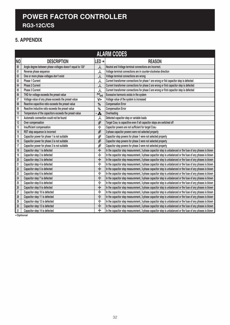
Angle degree between phase voltages doesn�t equal to 120°Reverse phase sequenceOne or more phase voltages don�t existPhase 1 CurrentPhase 2 CurrentPhase 3 CurrentTHD for voltage exceeds the preset valueVoltage value of any phase exceeds the preset valueReactive capacitive ratio exceeds the preset valueReactive inductive ratio exceeds the preset valueTemperature of the capacitors exceeds the preset valueAutomatic connection could not be foundOver compensationInsufficient compensationRST step sequence is incorrectCapacitor power for phase 1 is not suitableCapacitor power for phase 2 is not suitableCapacitor power for phase 3 is not suitableCapacitor step 1 is defectedCapacitor step 2 is defectedCapacitor step 3 is defectedCapacitor step 4 is defectedCapacitor step 5 is defectedCapacitor step 6 is defectedCapacitor step 7 is defectedCapacitor step 8 is defectedCapacitor step 9 is defectedCapacitor step 10 is defectedCapacitor step 11 is defectedCapacitor step 12 is defectedCapacitor step 13 is defectedCapacitor step 14 is defected
POWER FACTOR CONTROLLERRG3-12C/CS
32
NO DESCRIPTION REASON0001020304050607080910111213141516171819202122232425262728293031
ALARM CODES
Optional
LEDNeutral and Voltage terminal connections are incorrect.Voltage terminal connections are in counter-clockwise directionVoltage terminal connections are wrongCurrent transformer connections for phase 1 are wrong or fist capacitor step is defectedCurrent transformer connections for phase 2 are wrong or first capacitor step is defectedCurrent transformer connections for phase 3 are wrong or first capacitor step is defectedExcessive harmonic exists in the systemVoltage value of the system is increasedCompensation ErrorCompensation ErrorOverheatingDefected capacitor step or variable loadsTarget Cosj is capacitive even if all capacitor steps are switched offCapacitor powers are not sufficient for target Cosj
3-phase capacitor powers were not selected properlyCapacitor step powers for phase 1 were not selected properlyCapacitor step powers for phase 2 were not selected properlyCapacitor step powers for phase 3 were not selected properlyIn the capacitor step measurement, 3-phase capacitor step is unbalanced or the fuse of any phases is blownIn the capacitor step measurement, 3-phase capacitor step is unbalanced or the fuse of any phases is blownIn the capacitor step measurement, 3-phase capacitor step is unbalanced or the fuse of any phases is blownIn the capacitor step measurement, 3-phase capacitor step is unbalanced or the fuse of any phases is blownIn the capacitor step measurement, 3-phase capacitor step is unbalanced or the fuse of any phases is blownIn the capacitor step measurement, 3-phase capacitor step is unbalanced or the fuse of any phases is blownIn the capacitor step measurement, 3-phase capacitor step is unbalanced or the fuse of any phases is blownIn the capacitor step measurement, 3-phase capacitor step is unbalanced or the fuse of any phases is blownIn the capacitor step measurement, 3-phase capacitor step is unbalanced or the fuse of any phases is blownIn the capacitor step measurement, 3-phase capacitor step is unbalanced or the fuse of any phases is blownIn the capacitor step measurement, 3-phase capacitor step is unbalanced or the fuse of any phases is blownIn the capacitor step measurement, 3-phase capacitor step is unbalanced or the fuse of any phases is blownIn the capacitor step measurement, 3-phase capacitor step is unbalanced or the fuse of any phases is blownIn the capacitor step measurement, 3-phase capacitor step is unbalanced or the fuse of any phases is blown
5. APPENDIX

POWER FACTOR CONTROLLERRG3-12C/CS
REGISTER TABLE
33
REGISTER TABLE
READ
READ
READ
READ
READ
READ
READ
READ
READ
READ
READ
READ
READ
READ
READ
READ
READ
READ
READ
READ
READ
READ
READ
READ
READ
READ
READ
READ
VOLT
VOLT
VOLT
AMPERE
AMPERE
AMPERE
WATT
WATT
WATT
VAr
VAr
VAr
VA
VA
VA
-
-
-
WATT
WATT
VAr
VAr
VA
-
-
HZ
DEGREES
DEGREES
0.1
0.1
0.1
0.001
0.001
0.001
0.1
0.1
0.1
0.1
0.1
0.1
0.1
0.1
0.1
0.001
0.001
0.001
0.1
0.1
0.1
0.1
0.1
0.001
0.001
0.01
1
1
unsigned long int
unsigned long int
unsigned long int
unsigned long int
unsigned long int
unsigned long int
long int
long int
long int
long int
long int
long int
unsigned long int
unsigned long int
unsigned long int
long int
long int
long int
long int
long int
long int
long int
unsigned long int
long int
long int
long int
unsigned long int
long int
0000
0002
0004
0006
0008
000A
000C
000E
0010
0012
0014
0016
0018
001A
001C
001E
0020
0022
0024
0026
0028
002A
002C
002E
0030
0032
0034
0036
0
1
2
3
4
5
6
7
8
9
10
11
12
13
14
15
16
17
18
19
20
21
22
23
24
25
26
27
28
29
30
31
32
33
34
35
36
37
38
39
40
41
42
43
44
45
46
47
48
49
50
51
52
53
54
55
PHASE 1 VOLTAGE
PHASE 2 VOLTAGE
PHASE 3 VOLTAGE
PHASE 1 CURRENT
PHASE 2 CURRENT
PHASE 3 CURRENT
PHASE 1 ACTIVE POWER
PHASE 2 ACTIVE POWER
PHASE 3 ACTIVE POWER
PHASE 1 REACTIVE POWER
PHASE 2 REACTIVE POWER
PHASE 3 REACTIVE POWER
PHASE 1 APPARENT POWER
PHASE 2 APPARENT POWER
PHASE 3 APPARENT POWER
PHASE 1 COSj
PHASE 2 COSj
PHASE 3 COSj
TOTAL ACTIVE POWER (IMPORT)
TOTAL ACTIVE POWER (EXPORT)
TOTAL REACTIVE POWER (IMPORT)
TOTAL REACTIVE POWER (EXPORT)
TOTAL APPARENT POWER
COSj TOTAL IMPORT
COSj TOTAL EXPORT
FREQUENCY
PHASE 1 VOLTAGE VECTORIAL ANGLE
PHASE 2 VOLTAGE VECTORIAL ANGLE
NO PARAMETER FUNCTIONFORMAT UNITADDRESS (HEX) MULTIPLIER

POWER FACTOR CONTROLLERRG3-12C/CS
34
REGISTER TABLE
READ
READ
READ
READ
READ
READ
READ/CLEAR
READ
READ
READ/CLEAR
READ/CLEAR
READ/CLEAR
READ/CLEAR
READ/CLEAR
READ/CLEAR
READ/CLEAR
READ/CLEAR
READ
READ
READ
READ
READ
READ
DEGREES
DEGREES
DEGREES
DEGREES
CELCIUS
-
-
%
%
Wh
Wh
VArh
VArh
Wh
Wh
VArh
VArh
%
%
%
%
%
%
1
1
1
1
1
-
-
0.1
0.1
1
1
1
1
1
1
1
1
0.1
0.1
0.1
0.1
0.1
0.1
long int
long int
long int
long int
long int
long int
long int
long int
long int
64 BIT HEX
64 BIT HEX
64 BIT HEX
64 BIT HEX
64 BIT HEX
64 BIT HEX
64 BIT HEX
64 BIT HEX
unsigned int
unsigned int
unsigned int
unsigned int
unsigned int
unsigned int
0038
003A
003C
003E
0040
0042
0044
0046
0048
004A
004E
0052
0056
005A
005E
0062
0066
006A
006B
006C
006D
006E
006F
56
57
58
59
60
61
62
63
64
65
66
67
68
69
70
71
72
73
74
75
76
77
78
79
80
81
82
83
84
85
86
87
88
89
90
91
92
93
94
95
96
97
98
99
100
101
102
103
104
105
106
107
108
109
110
111
PHASE 3 VOLTAGE VECTORIAL ANGLE
PHASE 1 CURRENT VECTORIAL ANGLE
PHASE 2 CURRENT VECTORIAL ANGLE
PHASE 3 CURRENT VECTORIAL ANGLE
TEMPERATURE
CAPACITOR STEP STATUS
ALARM STATUS
INDUCTIVE REACTIVE ENERGY RATIO
CAPACITIVE REACTIVE ENERGY RATIO
IMPORT ACTIVE ENERGY COUNTER
EXPORT ACTIVE ENERGY COUNTER
IMPORT REACTIVE ENERGY COUNTER
EXPORT REACTIVE ENERGY COUNTER
IMPORT ACTIVE ENERGY COUNTER (RATIO)
EXPORT ACTIVE ENERGY COUNTER (RATIO)
IMPORT REACTIVE ENERGY COUNTER (RATIO)
EXPORT REACTIVE ENERGY COUNTER (RATIO)
PHASE 1 VOLTAGE THD
PHASE 1 VOLTAGE 3RD HARMONIC
PHASE 1 VOLTAGE 5TH HARMONIC
PHASE 1 VOLTAGE 7TH HARMONIC
PHASE 1 VOLTAGE 9TH HARMONIC
PHASE 1 VOLTAGE 11TH HARMONIC
NO PARAMETER FUNCTIONFORMAT UNITADDRESS (HEX) MULTIPLIER

POWER FACTOR CONTROLLERRG3-12C/CS
35
REGISTER TABLE
READ
READ
READ
READ
READ
READ
READ
READ
READ
READ
READ
READ
READ
READ
READ
READ
READ
READ
READ
READ
READ
READ
READ
READ
READ
READ
READ
READ
READ
READ
READ
READ
READ
READ
READ
READ
READ
READ
READ
READ
READ
READ
READ
READ
READ
READ
READ
READ
READ
READ
READ
READ
READ
READ
READ/WRITE
READ/WRITE
%
%
%
%
%
%
%
%
%
%
%
%
%
%
%
%
%
%
%
%
%
%
%
%
%
%
%
%
%
%
%
%
%
%
%
%
%
%
%
%
%
%
%
%
%
%
%
%
%
%
%
%
%
%
-
-
0.1
0.1
0.1
0.1
0.1
0.1
0.1
0.1
0.1
0.1
0.1
0.1
0.1
0.1
0.1
0.1
0.1
0.1
0.1
0.1
0.1
0.1
0.1
0.1
0.1
0.1
0.1
0.1
0.1
0.1
0.1
0.1
0.1
0.1
0.1
0.1
0.1
0.1
0.1
0.1
0.1
0.1
0.1
0.1
0.1
0.1
0.1
0.1
0.1
0.1
0.1
0.1
0.1
0.1
1
1
unsigned int
unsigned int
unsigned int
unsigned int
unsigned int
unsigned int
unsigned int
unsigned int
unsigned int
unsigned int
unsigned int
unsigned int
unsigned int
unsigned int
unsigned int
unsigned int
unsigned int
unsigned int
unsigned int
unsigned int
unsigned int
unsigned int
unsigned int
unsigned int
unsigned int
unsigned int
unsigned int
unsigned int
unsigned int
unsigned int
unsigned int
unsigned int
unsigned int
unsigned int
unsigned int
unsigned int
unsigned int
unsigned int
unsigned int
unsigned int
unsigned int
unsigned int
unsigned int
unsigned int
unsigned int
unsigned int
unsigned int
unsigned int
unsigned int
unsigned int
unsigned int
unsigned int
unsigned int
unsigned int
unsigned int
unsigned int
0070
0071
0072
0073
0074
0075
0076
0077
0078
0079
007A
007B
007C
007D
007E
007F
0080
0081
0082
0083
0084
0085
0086
0087
0088
0089
008A
008B
008C
008D
008E
008F
0090
0091
0092
0093
0094
0095
0096
0097
0098
0099
009A
009B
009C
009D
009E
009F
00A0
00A1
00A2
00A3
00A4
00A5
8000
8001
112
113
114
115
116
117
118
119
120
121
122
123
124
125
126
127
128
129
130
131
132
133
134
135
136
137
138
139
140
141
142
143
144
145
146
147
148
149
150
151
152
153
154
155
156
157
158
159
160
161
162
163
164
165
166
167
PHASE 1 VOLTAGE 13TH HARMONIC
PHASE 1 VOLTAGE 15TH HARMONIC
PHASE 1 VOLTAGE 17TH HARMONIC
PHASE 1 VOLTAGE 19TH HARMONIC
PHASE 1 CURRENT THD
PHASE 1 CURRENT 3RD HARMONIC
PHASE 1 CURRENT 5TH HARMONIC
PHASE 1 CURRENT 7TH HARMONIC
PHASE 1 CURRENT 9TH HARMONIC
PHASE 1 CURRENT 11TH HARMONIC
PHASE 1 CURRENT 13TH HARMONIC
PHASE 1 CURRENT 15TH HARMONIC
PHASE 1 CURRENT 17TH HARMONIC
PHASE 1 CURRENT 19TH HARMONIC
PHASE 2 VOLTAGE THD
PHASE 2 VOLTAGE 3RD HARMONIC
PHASE 2 VOLTAGE 5TH HARMONIC
PHASE 2 VOLTAGE 7TH HARMONIC
PHASE 2 VOLTAGE 9TH HARMONIC
PHASE 2 VOLTAGE 11TH HARMONIC
PHASE 2 VOLTAGE 13TH HARMONIC
PHASE 2 VOLTAGE 15TH HARMONIC
PHASE 2 VOLTAGE 17TH HARMONIC
PHASE 2 VOLTAGE 19TH HARMONIC
PHASE 2 CURRENT THD
PHASE 2 CURRENT 3RD HARMONIC
PHASE 2 CURRENT 5TH HARMONIC
PHASE 2 CURRENT 7TH HARMONIC
PHASE 2 CURRENT 9TH HARMONIC
PHASE 2 CURRENT 11TH HARMONIC
PHASE 2 CURRENT 13TH HARMONIC
PHASE 2 CURRENT 15TH HARMONIC
PHASE 2 CURRENT 17TH HARMONIC
PHASE 2 CURRENT 19TH HARMONIC
PHASE 3 VOLTAGE THD
PHASE 3 VOLTAGE 3RD HARMONIC
PHASE 3 VOLTAGE 5TH HARMONIC
PHASE 3 VOLTAGE 7TH HARMONIC
PHASE 3 VOLTAGE 9TH HARMONIC
PHASE 3 VOLTAGE 11TH HARMONIC
PHASE 3 VOLTAGE 13TH HARMONIC
PHASE 3 VOLTAGE 15TH HARMONIC
PHASE 3 VOLTAGE 17TH HARMONIC
PHASE 3 VOLTAGE 19TH HARMONIC
PHASE 3 CURRENT THD
PHASE 3 CURRENT 3RD HARMONIC
PHASE 3 CURRENT 5TH HARMONIC
PHASE 3 CURRENT 7TH HARMONIC
PHASE 3 CURRENT 9TH HARMONIC
PHASE 3 CURRENT 11TH HARMONIC
PHASE 3 CURRENT 13TH HARMONIC
PHASE 3 CURRENT 15TH HARMONIC
PHASE 3 CURRENT 17TH HARMONIC
PHASE 3 CURRENT 19TH HARMONIC
VOLTAGE TRANSFORMER RATIO
CURRENT TRANSFORMER RATIO
NO PARAMETER FUNCTIONFORMAT UNITADDRESS (HEX) MULTIPLIER

POWER FACTOR CONTROLLERRG3-12C/CS
36
REGISTER TABLE
READ/WRITE
READ/WRITE
READ/WRITE
READ/WRITE
READ/WRITE
READ/WRITE
READ/WRITE
READ/WRITE
READ/WRITE
READ/WRITE
READ/WRITE
READ/WRITE
READ/WRITE
READ/WRITE
READ/WRITE
READ/WRITE
READ/WRITE
READ/WRITE
READ/WRITE
READ/WRITE
READ/WRITE
READ/WRITE
READ/WRITE
READ/WRITE
READ/WRITE
READ/WRITE
READ/WRITE
READ/WRITE
READ/WRITE
-
READ/WRITE
READ/WRITE
READ/WRITE
READ/WRITE
READ/WRITE
READ/WRITE
READ/WRITE
READ/WRITE
READ/WRITE
READ/WRITE
READ/WRITE
READ/WRITE
READ/WRITE
READ/WRITE
READ/WRITE
READ/WRITE
READ/WRITE
READ/WRITE
READ/WRITE
READ/WRITE
READ/WRITE
READ/WRITE
READ/WRITE
READ/WRITE
READ/WRITE
READ/WRITE
READ/WRITE
READ/WRITE
-
-
-
-
-
SECOND
SECOND
SECOND
VOLT
SECOND
-
%
%
CELCIUS
CELCIUS
-
-
SECOND
-
-
-
-
-
-
-
-
CELCIUS
CELCIUS
HOUR
-
VAr
VAr
VAr
VAr
VAr
VAr
VAr
VAr
VAr
VAr
VAr
VAr
VAr
VAr
-
-
-
-
-
-
-
-
-
-
-
-
-
-
-
0.001
0.001
-
-
0.1
0.1
0.1
0.1
0.1
-
0.1
0.1
0.1
0.1
-
0.1
0.1
-
-
-
-
-
-
-
-
0.1
0.1
-
-
0.1
0.1
0.1
0.1
0.1
0.1
0.1
0.1
0.1
0.1
0.1
0.1
0.1
0.1
-
-
-
-
-
-
-
-
-
-
-
-
-
-
unsigned int
int
int
unsigned int
unsigned int
unsigned int
unsigned int
unsigned int
unsigned int
unsigned int
unsigned int
unsigned int
unsigned int
unsigned int
unsigned int
unsigned int
unsigned int
unsigned int
unsigned int
unsigned int
unsigned int
unsigned int
unsigned int
hex
unsigned int
unsigned int
unsigned int
unsigned int
unsigned int
-
unsigned int
unsigned int
unsigned int
unsigned int
unsigned int
unsigned int
unsigned int
unsigned int
unsigned int
unsigned int
unsigned int
unsigned int
unsigned int
unsigned int
unsigned int
unsigned int
unsigned int
unsigned int
unsigned int
unsigned int
unsigned int
unsigned int
unsigned int
unsigned int
unsigned int
unsigned int
unsigned int
unsigned int
8002
8003
8004
8005
8006
8007
8008
8009
800A
800B
800C
800D
800E
800F
8010
8011
8012
8013
8014
8015
8016
8017
8018
8019
801A
801B
801C
801D
801E
801F
8080
8081
8082
8083
8084
8085
8086
8087
8088
8089
808A
808B
808C
808D
808E
808F
8090
8091
8092
8093
8094
8095
8096
8097
8098
8099
809A
809B
168
169
170
171
172
173
174
175
176
177
178
179
180
181
182
183
184
185
186
187
188
189
190
191
192
193
194
195
196
197
198
199
200
201
202
203
204
205
206
207
208
209
210
211
212
213
214
215
216
217
218
219
220
221
222
223
224
225
NO PARAMETER FUNCTIONFORMAT UNITADDRESS (HEX) MULTIPLIERREACTIVE POWER CALCULATION METHOD
TARGET COSj
TARGET COSj 2
CAPACITOR STEP NUMBER
PROGRAM
SWITCH-ON TIME
SWITCH-OFF TIME
CAPACITOR STEP DISCHARGE TIME
OVER VOLTAGE SET VALUE
OVER VOLTAGE DELAY
OVER VOLTAGE CAPACITOR STEP
CAPACITIVE RATIO SET VALUE
INDUCTIVE RATIO SET VALUE
TEMPERATURE ALARM SET VALUE
TEMPERATURE ALARM END VALUE
TEMPERATURE ALARM STEP SITUATION
OVER THDV SET VALUE
OVER THDV DELAY
OVER THDV CAPACITOR STEP SITUATION
MODBUS ADDRESS
RS-485 BAUD RATE
RS-485 PARITY
PASSWORD ACTIVATION
PASSWORD
-
-
FAN OPERATING TEMPERATURE VALUE
FAN STOPPAGE TEMPERATURE VALUE
ENERGY RATIO READ TIME
-
1ST CAPACITOR STEP POWER
2ND CAPACITOR STEP POWER
3RD CAPACITOR STEP POWER
4TH CAPACITOR STEP POWER
5TH CAPACITOR STEP POWER
6TH CAPACITOR STEP POWER
7TH CAPACITOR STEP POWER
8TH CAPACITOR STEP POWER
9TH CAPACITOR STEP POWER
10TH CAPACITOR STEP POWER
11TH CAPACITOR STEP POWER
12TH CAPACITOR STEP POWER
13TH CAPACITOR STEP POWER
14TH CAPACITOR STEP POWER
1ST CAPACITOR STEP CONNECTION
2ND CAPACITOR STEP CONNECTION
3RD CAPACITOR STEP CONNECTION
4TH CAPACITOR STEP CONNECTION
5TH CAPACITOR STEP CONNECTION
6TH CAPACITOR STEP CONNECTION
7TH CAPACITOR STEP CONNECTION
8TH CAPACITOR STEP CONNECTION
9TH CAPACITOR STEP CONNECTION
10TH CAPACITOR STEP CONNECTION
11TH CAPACITOR STEP CONNECTION
12TH CAPACITOR STEP CONNECTION
13TH CAPACITOR STEP CONNECTION
14TH CAPACITOR STEP CONNECTION

POWER FACTOR CONTROLLERRG3-12C/CS
37
REGISTER TABLE
WRITE
WRITE
WRITE
WRITE
WRITE
WRITE
WRITE
WRITE
WRITE
WRITE
WRITE
WRITE
WRITE
WRITE
WRITE
WRITE
WRITE
WRITE
WRITE
-
-
-
-
-
-
-
-
-
-
-
-
-
-
-
-
-
-
-
-
-
-
-
-
-
-
-
-
-
-
-
-
-
-
-
-
-
-
-
-
-
-
-
-
-
-
-
-
-
-
-
-
-
-
-
-
-
9000
9001
9002
9003
9004
9005
9006
9007
9008
9009
900A
900B
900C
900D
900E
900F
9010
9011
9012
226
227
228
229
230
231
232
233
234
235
236
237
238
239
240
241
242
243
244
1ST CAPACITOR STEP SWITCH ON&OFF
2ND CAPACITOR STEP SWITCH ON&OFF
3RD CAPACITOR STEP SWITCH ON&OFF
4TH CAPACITOR STEP SWITCH ON&OFF
5TH CAPACITOR STEP SWITCH ON&OFF
6TH CAPACITOR STEP SWITCH ON&OFF
7TH CAPACITOR STEP SWITCH ON&OFF
8TH CAPACITOR STEP SWITCH ON&OFF
9TH CAPACITOR STEP SWITCH ON&OFF
10TH CAPACITOR STEP SWITCH ON&OFF
11TH CAPACITOR STEP SWITCH ON&OFF
12TH CAPACITOR STEP SWITCH ON&OFF
13TH CAPACITOR STEP SWITCH ON&OFF
14TH CAPACITOR STEP SWITCH ON&OFF
AUTOMATIC / MANUAL MODE SELECTION
AUTOMATIC SETUP
ALARM DELETE
ENERGY DELETE
RATIO DELETE
NO PARAMETER FUNCTIONFORMAT UNITADDRESS (HEX) MULTIPLIER

POWER FACTOR CONTROLLERRG3-12C/CS
38
In the first column, total reactive power values of 3-phase capacitors and in second & third columns, reactive power values of the capacitors insingle phase system are shown.
CAPACITOR CALCULATION TABLE
kVAr kVAr kVAr kVAr
kVAr kVAr kVAr kVAr
kVAr kVAr kVAr kVAr
kVAr kVAr kVAr kVAr
kVAr kVAr kVAr kVAr
kVAr kVAr kVAr kVAr
kVAr kVAr kVAr kVAr
kVAr kVAr kVAr kVAr
kVAr kVAr kVAr kVAr
kVAr kVAr kVAr kVAr
kVAr kVAr kVAr kVAr
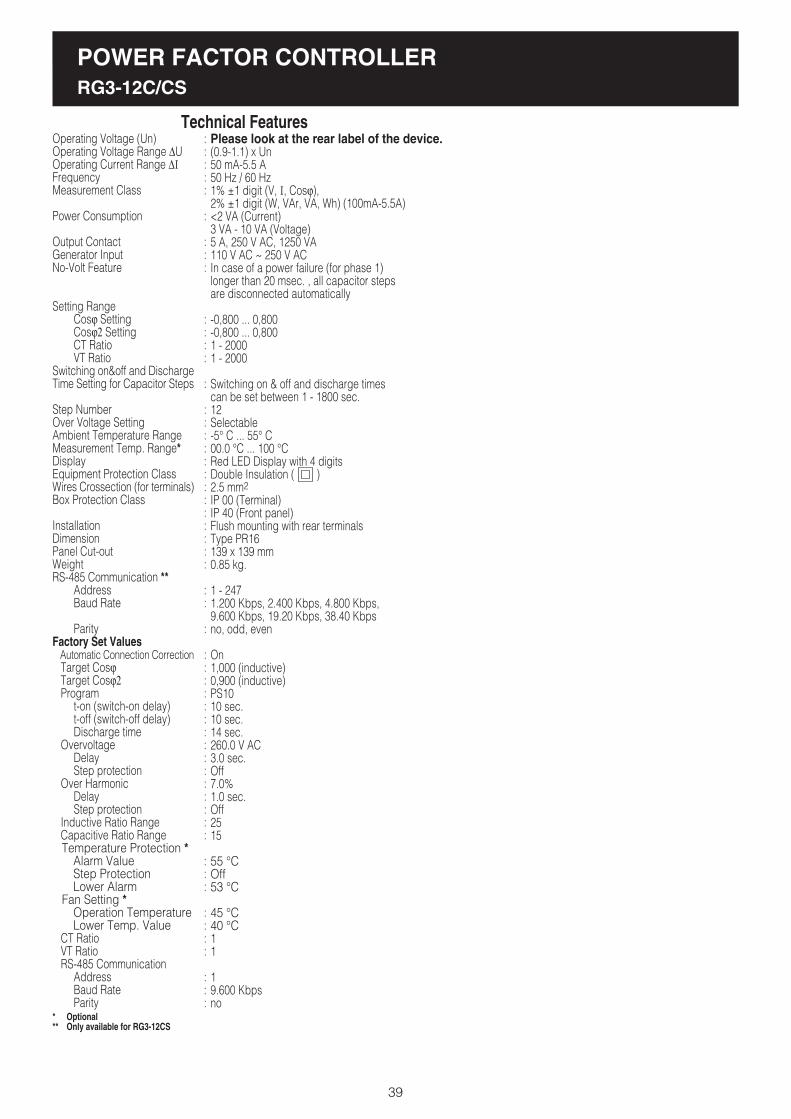
POWER FACTOR CONTROLLERRG3-12C/CS
39
Please look at the rear label of the device.(0.9-1.1) x Un50 mA-5.5 A50 Hz / 60 Hz1% ±1 digit (V, I, Cosj),2% ±1 digit (W, VAr, VA, Wh) (100mA-5.5A)<2 VA (Current)3 VA - 10 VA (Voltage)5 A, 250 V AC, 1250 VA110 V AC ~ 250 V ACIn case of a power failure (for phase 1)longer than 20 msec. , all capacitor stepsare disconnected automatically
-0,800 ... 0,800-0,800 ... 0,8001 - 20001 - 2000
Switching on & off and discharge timescan be set between 1 - 1800 sec.12Selectable-5° C ... 55° C00.0 °C ... 100 °CRed LED Display with 4 digitsDouble Insulation ( )2.5 mm2
IP 00 (Terminal)IP 40 (Front panel)Flush mounting with rear terminalsType PR16139 x 139 mm0.85 kg.
1 - 2471.200 Kbps, 2.400 Kbps, 4.800 Kbps,9.600 Kbps, 19.20 Kbps, 38.40 Kbpsno, odd, even
On1,000 (inductive)0,900 (inductive)PS1010 sec.10 sec.14 sec.260.0 V AC3.0 sec.Off7.0%1.0 sec.Off2515
55 °COff53 °C
45 °C40 °C11
19.600 Kbpsno
Operating Voltage (Un)Operating Voltage Range DUOperating Current Range DI
FrequencyMeasurement Class
Power Consumption
Output ContactGenerator InputNo-Volt Feature
Setting RangeCosj SettingCosj2 SettingCT RatioVT Ratio
Switching on&off and DischargeTime Setting for Capacitor Steps
Step NumberOver Voltage SettingAmbient Temperature RangeMeasurement Temp. Range*DisplayEquipment Protection ClassWires Crossection (for terminals)Box Protection Class
InstallationDimensionPanel Cut-outWeightRS-485 Communication **
AddressBaud Rate
ParityFactory Set Values Automatic Connection Correction Target Cosj Target Cosj2 Program
t-on (switch-on delay)t-off (switch-off delay)Discharge time
OvervoltageDelayStep protection
Over HarmonicDelayStep protection
Inductive Ratio Range Capacitive Ratio Range Temperature Protection *
Alarm ValueStep ProtectionLower Alarm
Fan Setting *Operation TemperatureLower Temp. Value
CT Ratio VT Ratio RS-485 Communication
AddressBaud RateParity
Technical Features:::::
:
:::
::::
:
:::::::::::::
::
:
:::::::::::::::
:::
::::
:::
* Optional** Only available for RG3-12CS
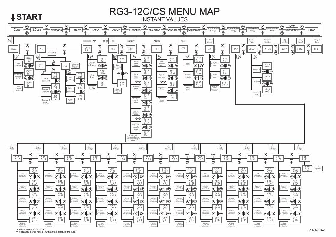
RG3-12C/CS MENU MAPINSTANT VALUES
ErrorApparentImport Active
EnergyCurrentsCosj Active Reactive
START
Voltages Temperature
CAP
C-02
CAP
C-03
CAP
C-04
CAP
C-05
CAP
C-06
CAP
C-07
CAP
C-08
CAP
C-09
CAP
C-10
CAP
C-11
CAP
C-12
12.Step
Settings
Cap
c-02
Cap
c-03
Cap
c-04
Cap
c-05
Cap
c-06
Cap
c-07
Cap
c-08
Cap
c-09
Cap
c-10
Cap
c-11
Cap
c-12
Capc-02off
Cap
c-02
Cap
c-02
Cap
c-02
Capc-03off
Cap
c-03
Cap
c-03
Cap
c-03
Capc-04off
Cap
c-04
Cap
c-04
Cap
c-04
Capc-05off
Cap
c-05
Cap
c-05
Cap
c-05
Capc-06off
Cap
c-06
Cap
c-06
Cap
c-06
Capc-07off
Cap
c-07
Cap
c-07
Cap
c-07
Capc-08off
Cap
c-08
Cap
c-08
Cap
c-08
Capc-09off
Cap
c-09
Cap
c-09
Cap
c-09
Capc-10off
Cap
c-10
Cap
c-10
Cap
c-10
Capc-11off
Cap
c-11
Cap
c-11
Cap
c-11
Capc-12off
Cap
c-12
Cap
c-12
Cap
c-12
SCosj SActive SReactive SApparentExport Active
EnergyIndüctive Reactive
EnergyCapacitive Reactive
Energy
11.Step
Settings
10.Step
Settings
9.Step
Settings
8.Step
Settings
7.Step
Settings
6.Step
Settings
5.Step
Settings
4.Step
Settings
3.Step
Settings
2.Step
Settings
1.Step
Settings
DeltaConnected
to Capacitor
A4917/Rev.1
SET
DeltaConnected
to Capacitor
Capacitoris not
Connected
R-PhaseConnected
to Capacitor
S-PhaseConnected
to Capacitor
T-PhaseConnected
to Capacitor
DeltaConnected
to Capacitor
Capacitoris not
Connected
R-PhaseConnected
to Capacitor
S-PhaseConnected
to Capacitor
T-PhaseConnected
to Capacitor
DeltaConnected
to Capacitor
Capacitoris not
Connected
R-PhaseConnected
to Capacitor
S-PhaseConnected
to Capacitor
T-PhaseConnected
to Capacitor
DeltaConnected
to Capacitor
Capacitoris not
Connected
R-PhaseConnected
to Capacitor
S-PhaseConnected
to Capacitor
T-PhaseConnected
to Capacitor
DeltaConnected
to Capacitor
Capacitoris not
Connected
R-PhaseConnected
to Capacitor
S-PhaseConnected
to Capacitor
T-PhaseConnected
to Capacitor
DeltaConnected
to Capacitor
Capacitoris not
Connected
R-PhaseConnected
to Capacitor
S-PhaseConnected
to Capacitor
T-PhaseConnected
to Capacitor
DeltaConnected
to Capacitor
Capacitoris not
Connected
R-PhaseConnected
to Capacitor
S-PhaseConnected
to Capacitor
T-PhaseConnected
to Capacitor
DeltaConnected
to Capacitor
Capacitoris not
Connected
R-PhaseConnected
to Capacitor
S-PhaseConnected
to Capacitor
T-PhaseConnected
to Capacitor
DeltaConnected
to Capacitor
Capacitoris not
Connected
R-PhaseConnected
to Capacitor
S-PhaseConnected
to Capacitor
T-PhaseConnected
to Capacitor
DeltaConnected
to Capacitor
Capacitoris not
Connected
R-PhaseConnected
to Capacitor
S-PhaseConnected
to Capacitor
T-PhaseConnected
to Capacitor
DeltaConnected
to Capacitor
Capacitoris not
Connected
R-PhaseConnected
to Capacitor
S-PhaseConnected
to Capacitor
T-PhaseConnected
to Capacitor
Available for RG3-12CS.Not available for models without temperature module.
Password
EnterPassword
ChangingPassword
Menu
EnterOld
Password
EnterNew
Password
ReenterNew
Password
DeviceAddress
BaudRate
AutoManual
Auto ConnectionRecognition
On/Off
Parity
OverVoltageAlarm
AlarmReset
CurrentTransformer
Ratio
Delay-ON
AU
AU
Pe
AUSeUp
S-4
85
485
A
485
AU
485
A
A
A
A E
A
EA
A
AESE
ESE
A A
A E
E
ESE
ESE
CAP
Communication Alarm ResetTransformer
SettingsDelayTime
ProgramSelection
Max.Step
Number
Delay-OFF
DischargeDelay
VoltageTransformer
Ratio
Reactive/Active
Ratio Reset
EnergyReset
Reactive/Active
Ratio Alarm
TemperatureAlarm
HarmonicAlarm
THD I-V
COS2
TargetCosj2
COS
TargetCosj
PasswordDisabled
PasswordEnabled
SET
SET
SET
SET
SET
SET
SET
SET SET SET SET SET SET
Fan
FanSwitch-on
Value
FanSwitch-off
Value
SET
AutoCapacitor
Calculation
AUSeUp
ActiveImportValue
Energy
ActiveExportValue
ReactiveImportValue
ReactiveExportValue
SET
EnergyCounter
Reset
GeneratorEnergyCounter
Reset
Activate theGenerator Energy
Counter with DigitalInput
ReactiveEnergy
CalculationMethode