Embed Size (px)
Citation preview

1ECEN 489: Power Management Circuits and Systems
Power computations

2ECEN 489: Power Management Circuits and Systems
Power and Energy
• Instantaneous power p(t) is defined as the product of instantaneous voltage v(t) and instantaneous current i(t).
𝑝 𝑡 = 𝑣(𝑡)𝑖(𝑡)
• Average power P is the time average of p(t) over one or more periods
𝑃 =1
𝑇න𝑡𝑜
𝑡𝑜+𝑇
𝑝(𝑡) 𝑑𝑡
T is the period of the power waveform

3ECEN 489: Power Management Circuits and Systems
Power and Energy
• Energy, or work, is the integral of instantaneous power
𝑊 = න𝑡1
𝑡2
𝑝(𝑡) 𝑑𝑡
• Power has units of watts and energy has units of joules.
• Power can also computed from energy per period
𝑃 =𝑊
𝑇

4ECEN 489: Power Management Circuits and Systems
Power and Energy
Example

5ECEN 489: Power Management Circuits and Systems
Power and Energy
Example contd
• Energy absorbed by the device in one period
• Average power is
= 60𝑊
𝑃 =𝑊
𝑇=
1.2𝐽
0.02𝑠= 60𝑊

6ECEN 489: Power Management Circuits and Systems
Power and Energy
• For applications such as battery charging circuits and DC power supplies, average power absorbed by a dc voltage source 𝑣 𝑡 = 𝑉𝑑𝑐 that has a periodic current i(t) is 𝑃𝑑𝑐
• Average power absorbed by a dc voltage source is the product of the voltage and the average current
𝑃𝑑𝑐 = 𝑉𝑑𝑐𝐼𝑎𝑣𝑔• Average power absorbed by a dc source 𝑖 𝑡 = 𝐼𝑑𝑐
𝑃𝑑𝑐 = 𝑉𝑎𝑣𝑔𝐼𝑑𝑐

7ECEN 489: Power Management Circuits and Systems
Inductors
• For periodic currents and voltages,
𝑖 𝑡 + 𝑇 = 𝑖 𝑡𝑣 𝑡 + 𝑇 = 𝑣 𝑡
• Voltage-current relationship for the inductor
𝑖 𝑡𝑜 + 𝑇 =1
𝐿න𝑡𝑜
𝑡𝑜+𝑇
𝑉𝐿 𝑡 𝑑𝑡 + 𝑖(𝑡𝑜)
• Energy stored in an inductor
𝑤 𝑡 =1
2𝐿𝑖2(𝑡)
• For periodic inductor current, stored energy at the end of one period is the same as at the beginning
• No net energy transfer indicates that the average power absorbed by an inductor is zero for steady-state periodic operation
𝑃𝐿 = 0
𝑖 𝑡𝑜 + 𝑇 − 𝑖 𝑡𝑜 =1
𝐿න𝑡𝑜
𝑡𝑜+𝑇
𝑉𝐿 𝑡 𝑑𝑡
𝑎𝑣𝑔 𝑉𝐿 𝑡 = 𝑉𝐿 =1
𝑇න𝑡𝑜
𝑡𝑜+𝑇
𝑉𝐿 𝑡 𝑑𝑡 = 0
For periodic currents, the average voltage across an inductor is zero

8ECEN 489: Power Management Circuits and Systems
Capacitors• Voltage-current relationship for the inductor
𝑣 𝑡𝑜 + 𝑇 =1
𝐶න𝑡𝑜
𝑡𝑜+𝑇
𝑖𝑐 𝑡 𝑑𝑡 + 𝑣(𝑡𝑜)
• Energy stored in an capacitor
𝑤 𝑡 =1
2𝐶𝑣2(𝑡)
• For a periodic capacitor voltage, the stored energy is the same at the end of a period as at the beginning.
• No net energy transfer indicates that the average power absorbed by the capacitor is zero for steady-state periodic operation
𝑃𝑐 = 0
𝑣 𝑡𝑜 + 𝑇 − 𝑣 𝑡𝑜 =1
𝐶න𝑡𝑜
𝑡𝑜+𝑇
𝑖𝑐 𝑡 𝑑𝑡 = 0
𝑎𝑣𝑔 𝑖𝑐 𝑡 = 𝐼𝐶 =1
𝑇න𝑡𝑜
𝑡𝑜+𝑇
𝑖𝐶 𝑡 𝑑𝑡 = 0
For periodic voltages, the average current in a capacitor is zero

9ECEN 489: Power Management Circuits and Systems
Inductors and Capacitors
ExampleDetermine the voltage, instantaneous power, and
average power for the inductor
• Remember average inductor voltage is zero
• 𝑝 𝑡 = 𝑣(𝑡)𝑖(𝑡)
Average inductor power is 0

10ECEN 489: Power Management Circuits and Systems
Energy recovery
• For 0 < 𝑡 < 𝑡1
𝑣𝐿 = 𝑉𝐶𝐶
𝑖𝑠(𝑡) = 𝑖𝐿(𝑡)

11ECEN 489: Power Management Circuits and Systems
Energy recovery
For 𝑡1 < 𝑡 < 𝑇
• Initial condition for inductor current
• Average power supplied by dc source

12ECEN 489: Power Management Circuits and Systems
Effective values: RMS
• Effective value of a voltage or current is also known as the root-mean-square (rms) value
• Effective value of a periodic voltage waveform is based on the average power delivered to a resistor
• For a periodic voltage across a resistor, effective voltage is the voltage that is as effective as the dc
voltage in supplying average power
𝑃 =𝑉𝑑𝑐
2
𝑅; 𝑃 =
𝑉𝑒𝑓𝑓2
𝑅• Average resistor power
⇒

13ECEN 489: Power Management Circuits and Systems
Effective values: RMS
• Example: Find the rms of a periodic pulse waveform

14ECEN 489: Power Management Circuits and Systems
Effective values: RMS
• If a periodic voltage is the sum of two periodic voltage waveforms
𝑣 𝑡 = 𝑣1 𝑡 + 𝑣2(𝑡), the rms value of v(t)
• For orthogonal functions

15ECEN 489: Power Management Circuits and Systems
Effective values: RMS
Examples
=

16ECEN 489: Power Management Circuits and Systems
Apparent power and power factor
• Apparent power is the product of rms voltage and rms current magnitudes
𝑆 = 𝑉𝑟𝑚𝑠𝐼𝑟𝑚𝑠
• Power factor is the ratio of average power to apparent power
𝑝𝑓 =𝑃
𝑆=
𝑃
𝑉𝑟𝑚𝑠𝐼𝑟𝑚𝑠
𝑝𝑓 = cosΦ
• Lagging power factor– Current lags behind voltage
– Circuit is inductive
• Leading power factor– Current leads voltage
– Circuit is capacitive
• Unity power factor– Current and voltage in phase
– ideal
lagging
leading
In phase

17ECEN 489: Power Management Circuits and Systems
Power computations for sinusoidal
ac circuits
• For linear circuits that have sinusoidal sources, all steady-state voltages and currents are sinusoids
• For
𝑣 𝑡 = 𝑉𝑚cos(ω𝑡 + θ)𝑖 𝑡 = 𝐼𝑚cos(ω𝑡 + Φ)
• Instantaneous power
𝑝 𝑡 = [𝑉𝑚cos ω𝑡 + θ ][𝐼𝑚 cos ω𝑡 + Φ ]
𝑝 𝑡 =𝐼𝑚𝑉𝑚2
[cos 2ω𝑡 + θ + Φ + cos θ − Φ ]
• Average power
𝑃 =1
𝑇න0
𝑇
𝑝 𝑡 𝑑𝑡 =𝐼𝑚𝑉𝑚2
1
𝑇න0
𝑇
[cos 2ω𝑡 + θ + Φ + cos θ − Φ ]𝑑𝑡
𝑃 =𝐼𝑚𝑉𝑚2
cos θ − Φ
𝑃 = 𝑉𝑟𝑚𝑠𝐼𝑟𝑚𝑠 cos θ − Φ
Power factor
θ − Φ is the phase angle between voltage and current

18ECEN 489: Power Management Circuits and Systems
Power computations for sinusoidal
ac circuits
• Remember: In the steady state, no net power is absorbed by an inductor or a capacitor
• Reactive power is commonly used in conjunction with voltages and currents for inductors and capacitors
• Reactive power is characterized by energy storage during one-half of the cycle and energy retrieval during the other half
𝑄 = 𝑉𝑟𝑚𝑠𝐼𝑟𝑚𝑠 sin θ − Φ• Complex power combines real and reactive powers for ac circuits
𝑆 = 𝑃 + 𝑗𝑄 = 𝑉𝑟𝑚𝑠𝐼𝑟𝑚𝑠∗
• Apparent power in ac circuits is the magnitude of complex power
𝑆 = 𝑆 = 𝑃2 + 𝑄2

19ECEN 489: Power Management Circuits and Systems
Power computations for nonsinusoidal
periodic waveforms
• Power electronics circuits typically have voltages and/or currents that are periodic but not sinusoidal
• Applying some special relationships for sinusoids to waveforms that are not sinusoids can cause errors
• Option to use Fourier series to describe nonsinusoidal periodic waveforms in terms of a series of sinusoids
• A periodic function f(t) can be expressed in trigonometric form
• Sines and cosines can be combined into one sinusoid
or
• rms value of f(t)

20ECEN 489: Power Management Circuits and Systems
Power computations for nonsinusoidal
periodic waveforms
• Average power
• Average power for nonsinusoidal periodic voltage and current waveforms
𝑃 =1
𝑇න0
𝑇
𝑝(𝑡) 𝑑𝑡
or
Total average power is the sum of the powers at the frequencies in the Fourier series

21ECEN 489: Power Management Circuits and Systems
Power computations for nonsinusoidal
periodic waveforms
• For a nonsinusoidal source applied to a linear load, use superposition
to determine power absorbed by load
•Nonsinusoidal periodic voltage is equivalent to the series combination
of the Fourier series voltages
= load
22ECEN 489: Power Management Circuits and Systems
Power computations for nonsinusoidal
periodic waveforms
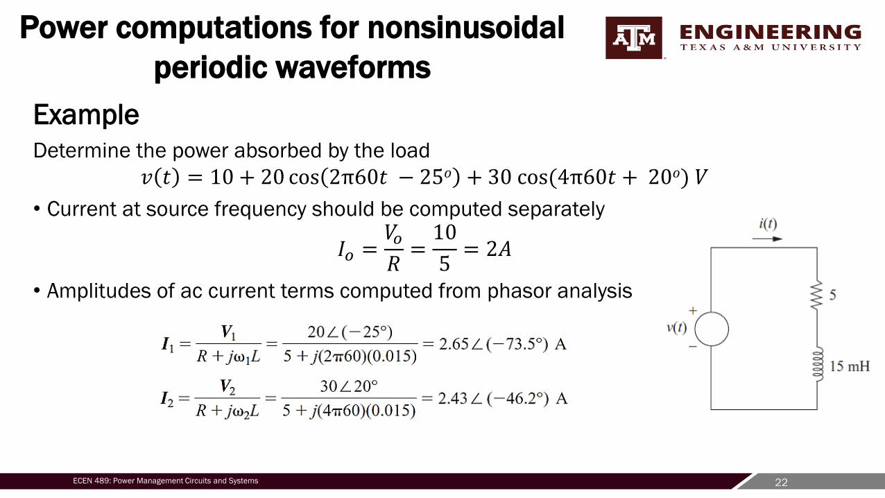
Example
Determine the power absorbed by the load
𝑣 𝑡 = 10 + 20 cos 2π60𝑡 − 25𝑜 + 30 cos(4π60𝑡 + 20𝑜) 𝑉
• Current at source frequency should be computed separately
𝐼𝑜 =𝑉𝑜𝑅=10
5= 2𝐴
• Amplitudes of ac current terms computed from phasor analysis

23ECEN 489: Power Management Circuits and Systems
Power computations for nonsinusoidal
periodic waveforms
Example• Load current
• Power at each frequency in Fourier series
• Total power
• Power absorbed by load can computed from 𝐼𝑟𝑚𝑠2𝑅

24ECEN 489: Power Management Circuits and Systems
Power computations for nonsinusoidal
periodic waveforms
• If a sinusoidal voltage source is applied to a nonlinear load, current
waveform can be represented as a Fourier series
Only nonzero power term is at the frequency of the applied voltage
Power factor, 𝑝𝑓 =𝑃
𝑆=
𝑃
𝑉𝑟𝑚𝑠𝐼𝑟𝑚𝑠
𝑝𝑓 =𝑉1,𝑟𝑚𝑠𝐼1,𝑟𝑚𝑠 cos(θ1−Φ1)
𝑉1,𝑟𝑚𝑠𝐼𝑟𝑚𝑠=𝐼1,𝑟𝑚𝑠 cos(θ1−Φ1)
𝐼𝑟𝑚𝑠

25ECEN 489: Power Management Circuits and Systems
Power computations for nonsinusoidal
periodic waveforms
• Distortion factor- ratio of the rms value of the fundamental frequency to the total rms value
• Distortion factor represents the reduction in power factor due to the nonsinusoidal property of the current
• Total harmonic distortion (THD) is another term used to quantify the nonsinusoidal property of a waveform
• THD is the ratio of the rms value of all the nonfundamental frequency terms to the rms value of the
fundamental frequency term
• Distortion factor can be expressed as
• Power factor can also be expressed as
• THD can be expressed as Distortion factor can also be expressed as

26ECEN 489: Power Management Circuits and Systems
Power computations for nonsinusoidal
periodic waveforms
Example
• A sinusoidal voltage source of v(t) =100 cos(377t) V is applied to a nonlinear load,
resulting in a nonsinusoidal current which is expressed in Fourier series form
Determine
• power absorbed by the load
• power factor of the load
• distortion factor of the load current
• total harmonic distortion of the load current

27ECEN 489: Power Management Circuits and Systems
Power computations for nonsinusoidal
periodic waveforms
Solution
• v(t) =100 cos(377t) and
• Power absorbed by the load- power absorbed at each frequency in Fourier series
• rms voltage • Power factor=𝑃
𝑆=
𝑃
𝑉𝑟𝑚𝑠𝐼𝑟𝑚𝑠=
650
70.7∗14.0= 0.66
or

28ECEN 489: Power Management Circuits and Systems
Power computations for nonsinusoidal
periodic waveforms
Solution
• v(t) =100 cos(377t) and
• Distortion factor can be expressed as
• Total harmonic distortion of load current

29ECEN 489: Power Management Circuits and Systems
Summary
• Instantaneous power p(t) is 𝑝 𝑡 = 𝑣 𝑡 𝑖 𝑡
• Average power P 𝑃 =1
𝑇𝑡𝑜𝑡𝑜+𝑇 𝑝(𝑡) 𝑑𝑡
• For inductors and capacitors that have periodic voltages and currents, the average power is zero.
Instantaneous power is generally not zero because the device store energy and then returns energy
to the circuit.
• For periodic currents, the average voltage across an inductor is zero.
• For periodic voltages, the average current in a capacitor is zero.
• For nonsinusoidal periodic waveforms, average power may be computed from the basic definition,
or the Fourier series method may be used. The Fourier series method treats each frequency in the
series separately and uses superposition to compute total power.
• Power factor is the ratio of average power to apparent power
• Apparent power is the product of rms voltage and current
• The rms value is the root-mean-square or effective value of a voltage or current waveform