Embed Size (px)
Citation preview
Power-Line Communication-Revisited in the Context of Smart Grid
Saurabh Chaudhury Sourav Bhattacharjee
Abstract— Power-line communication (PLC) is an integral part of Smart Grid today. This paper describes a novel analysis of a PLC channel for transmission and reception of analog signals namely, the voice/speech. It takes into consideration all possible noises that may get introduced into the channel. The noises that affect the performance of power line communications are mainly impulsive noise, narrow band noise and color background noise. In this paper, a model of power line communication channel, specifically, the SRC model is considered for analysis, however, the simulation results are also compared with echo model. Amplitude modulation/demodulation is used for signal transmission/reception and Weiner filter is used for noise suppression. It is seen that SRC model of PLC is the right candidate for analog transmission of speech signal if we compare the input and out signal in terms of SNR and the quality of the signal received.
Keywords— PLC, analog transmission, modulation, Weiner filter, signal quality
I. Introduction
The idea of sending communication signal over the same power lines (which is mainly used to distribute electrical power) is as old as telegraph itself. Power Line Communications uses the existing power cable infrastructure for communication purposes. It is becoming one of the strong competitors in the broadband communication market. However, it also faces its own set of obstacles and technical challenges. With the goal of providing operational telephone services and data communications across large geographical distances, the first power line communications (PLC) efforts were put in place by power utilities over HV power grid in the early 1920s. For some decades, the omnipresent power grid has been used for low-speed data communications [1]. Many different standardised or proprietary systems have been used for the transmission of control and management signals (e.g. remote meter reading) by
power supply companies. However, the power line has largely been dismissed as being too noisy and unpredictable to be useful as a practical high-speed communication channel. A significant change occurred when the last telecommunication monopolies were ended by 1998. In the same time, major advances in the fields of modulation, coding and detection enabled the design of efficient broadband communication systems over power lines. The idea of exploiting the low-voltage (LV) power grid to provide broadband Internet access to residential customers has been proposed as an alternative to the other classical `last-mile solutions' such as ADSL, cable modems, or wireless access systems. The ubiquitous presence of the low-voltage (LV), medium-voltage (MV), and high-voltage (HV) power grids is the key to developing an advanced smart grid power network. The deployment of broadband over power lines (BPL) networks through the entire grid forms a potentially convenient and inexpensive communication medium for delivering broadband last mile access in remote and/or underdeveloped areas [2]. Due to the upcoming Smart Grid adaption both in transmission and distribution power networks, the availability of a reliable communication network on the HV power grid side is important for the support of these significant changes [3 - 5]. Since overhead HV power lines are generally the lowest-cost method of transmission for large quantities of electric power, utilities employ primarily overhead HV transmission power grid for new urban, suburban, and rural installations [6 - 7]. LV power line communication (PLC) networks have a tree-like topology, with a PLC modem installed at the medium-voltage/low-voltage (MV/LV) transformer and providing connectivity to all premises in the neighbourhood. The architecture of the LV PLC network has to be optimized for the special characteristics of the distribution grid, which changes
Mathematics and Computers in Science and Industry
ISBN: 978-1-61804-247-7 355
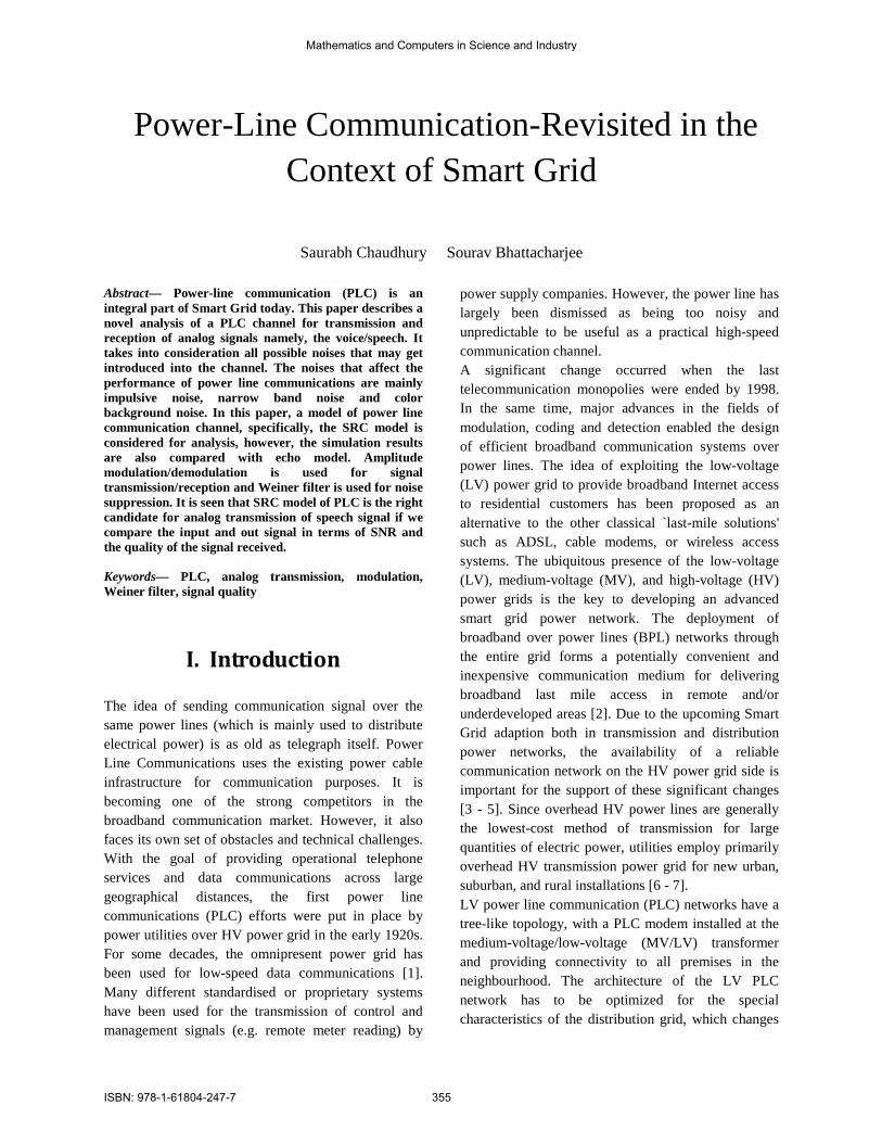
from one geographic area to another, considering the number of households per transformer and the distance from the transformer to the customer premises. When larger distances are involved, intermediate repeaters are typically needed to regenerate the signal from the head-end and provide adequate coverage in every customer outlet. There is also growing interest in the prospects of reusing in-building powerline cables to provide a broadband LAN within the home or office. Major advantage offered by power line based home networks is the availability of an existing infrastructure of wires and wall outlets, so new cable installation is not required. The user can employ home networking devices for connecting several computers, sharing printers, or sharing a broadband Internet connection. Channel characteristics of the power line show a typical behavior which is briefly described here. Impedance is highly varying with frequency and ranges from a few Ohm to few kilo Ohm. At some frequencies there are peaks in the impedance characteristics. At these peaks the network behaves like a parallel resonant circuit. However, in most of the frequency ranges the impedance shows inductive or capacitive behavior. Characteristic impedance of a power line cable is typically in the range of 90 Ohm. The overall impedance is not only influenced by characteristic impedance but also by network topology and connected loads which may have highly varying impedances as well. Moreover, the PLC channel is highly influenced by the noise spectrum. The noise spectrum is highly varying with frequency and time. There is an overall decay of the noise level with increasing frequency. A typical example of a measured noise spectrum is shown in Fig. 1. Noise at the power line is influenced by a large number of different noise sources with different characteristics. Section 2 describes all such noises in detail. We have limited our scope of work in this paper considering the following noises.
• Coloured background noise • Narrow-band noise • Impulsive noise (both periodic and aperiodic)
Figure 1: Example of Measured Noise Spectrum
Next section describes all these different kinds of noises, their characteristic behavior and models. Section 3 describes the PLC channel and the overall scheme for analog signal transmission-reception through PLC. Next, in section 4 results of simulation are presented and finally the paper concludes in section 5.
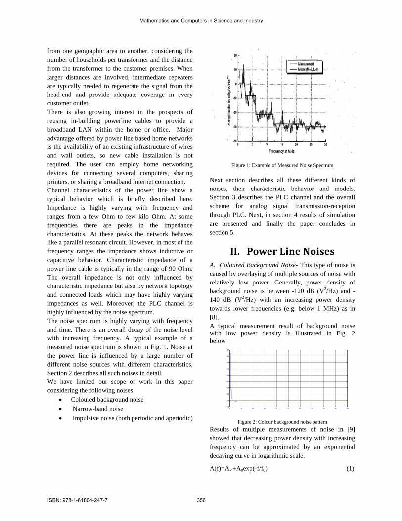
II. Power Line Noises A. Coloured Background Noise- This type of noise is caused by overlaying of multiple sources of noise with relatively low power. Generally, power density of background noise is between -120 dB (V2/Hz) and -140 dB (V2/Hz) with an increasing power density towards lower frequencies (e.g. below 1 MHz) as in [8]. A typical measurement result of background noise with low power density is illustrated in Fig. 2 below
0 10 20 30 40 50 60 70 80 90 100-140
-135
-130
-125
-120
-115
-110
-105
-100
-95
Figure 2: Colour background noise pattern
Results of multiple measurements of noise in [9] showed that decreasing power density with increasing frequency can be approximated by an exponential decaying curve in logarithmic scale.
A(f)=A∞+A0exp(-f/f0) (1)
Mathematics and Computers in Science and Industry
ISBN: 978-1-61804-247-7 356
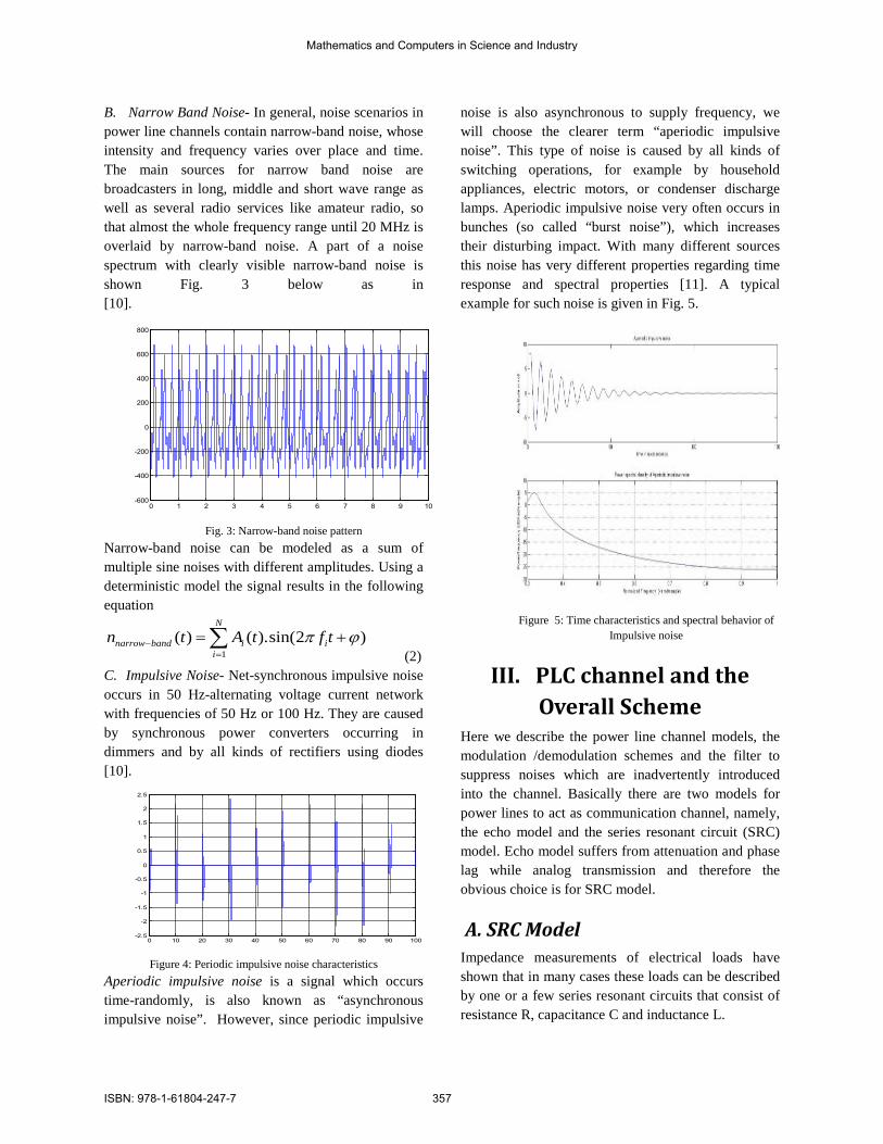
B. Narrow Band Noise- In general, noise scenarios in power line channels contain narrow-band noise, whose intensity and frequency varies over place and time. The main sources for narrow band noise are broadcasters in long, middle and short wave range as well as several radio services like amateur radio, so that almost the whole frequency range until 20 MHz is overlaid by narrow-band noise. A part of a noise spectrum with clearly visible narrow-band noise is shown Fig. 3 below as in [10].
0 1 2 3 4 5 6 7 8 9 10-600
-400
-200
0
200
400
600
800
Fig. 3: Narrow-band noise pattern Narrow-band noise can be modeled as a sum of multiple sine noises with different amplitudes. Using a deterministic model the signal results in the following equation
1( ) ( ).sin(2 )
N
narrow band i ii
n t A t f tπ ϕ−=
= +∑ (2)
C. Impulsive Noise- Net-synchronous impulsive noise occurs in 50 Hz-alternating voltage current network with frequencies of 50 Hz or 100 Hz. They are caused by synchronous power converters occurring in dimmers and by all kinds of rectifiers using diodes [10].
0 10 20 30 40 50 60 70 80 90 100-2.5
-2
-1.5
-1
-0.5
0
0.5
1
1.5
2
2.5
Figure 4: Periodic impulsive noise characteristics
Aperiodic impulsive noise is a signal which occurs time-randomly, is also known as “asynchronous impulsive noise”. However, since periodic impulsive
noise is also asynchronous to supply frequency, we will choose the clearer term “aperiodic impulsive noise”. This type of noise is caused by all kinds of switching operations, for example by household appliances, electric motors, or condenser discharge lamps. Aperiodic impulsive noise very often occurs in bunches (so called “burst noise”), which increases their disturbing impact. With many different sources this noise has very different properties regarding time response and spectral properties [11]. A typical example for such noise is given in Fig. 5.
Figure 5: Time characteristics and spectral behavior of
Impulsive noise
III. PLC channel and the Overall Scheme
Here we describe the power line channel models, the modulation /demodulation schemes and the filter to suppress noises which are inadvertently introduced into the channel. Basically there are two models for power lines to act as communication channel, namely, the echo model and the series resonant circuit (SRC) model. Echo model suffers from attenuation and phase lag while analog transmission and therefore the obvious choice is for SRC model.
A. SRC Model Impedance measurements of electrical loads have shown that in many cases these loads can be described by one or a few series resonant circuits that consist of resistance R, capacitance C and inductance L.
Mathematics and Computers in Science and Industry
ISBN: 978-1-61804-247-7 357
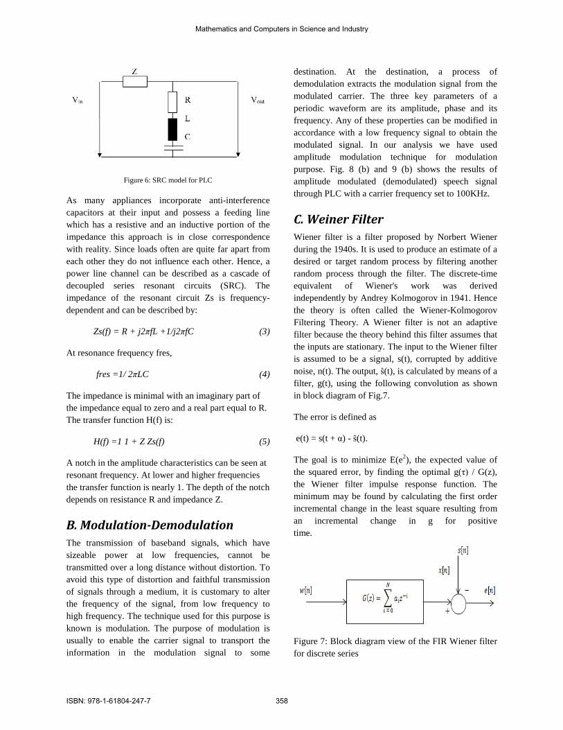
Figure 6: SRC model for PLC
As many appliances incorporate anti-interference capacitors at their input and possess a feeding line which has a resistive and an inductive portion of the impedance this approach is in close correspondence with reality. Since loads often are quite far apart from each other they do not influence each other. Hence, a power line channel can be described as a cascade of decoupled series resonant circuits (SRC). The impedance of the resonant circuit Zs is frequency- dependent and can be described by:
Zs(f) = R + j2πfL +1/j2πfC (3)
At resonance frequency fres,
fres =1/ 2πLC (4)
The impedance is minimal with an imaginary part of the impedance equal to zero and a real part equal to R. The transfer function H(f) is:
H(f) =1 1 + Z Zs(f) (5)
A notch in the amplitude characteristics can be seen at resonant frequency. At lower and higher frequencies the transfer function is nearly 1. The depth of the notch depends on resistance R and impedance Z.
B. Modulation-Demodulation The transmission of baseband signals, which have sizeable power at low frequencies, cannot be transmitted over a long distance without distortion. To avoid this type of distortion and faithful transmission of signals through a medium, it is customary to alter the frequency of the signal, from low frequency to high frequency. The technique used for this purpose is known is modulation. The purpose of modulation is usually to enable the carrier signal to transport the information in the modulation signal to some
destination. At the destination, a process of demodulation extracts the modulation signal from the modulated carrier. The three key parameters of a periodic waveform are its amplitude, phase and its frequency. Any of these properties can be modified in accordance with a low frequency signal to obtain the modulated signal. In our analysis we have used amplitude modulation technique for modulation purpose. Fig. 8 (b) and 9 (b) shows the results of amplitude modulated (demodulated) speech signal through PLC with a carrier frequency set to 100KHz.
C. Weiner Filter Wiener filter is a filter proposed by Norbert Wiener during the 1940s. It is used to produce an estimate of a desired or target random process by filtering another random process through the filter. The discrete-time equivalent of Wiener's work was derived independently by Andrey Kolmogorov in 1941. Hence the theory is often called the Wiener-Kolmogorov Filtering Theory. A Wiener filter is not an adaptive filter because the theory behind this filter assumes that the inputs are stationary. The input to the Wiener filter is assumed to be a signal, s(t), corrupted by additive noise, n(t). The output, ŝ(t), is calculated by means of a filter, g(t), using the following convolution as shown in block diagram of Fig.7.
The error is defined as
e(t) = s(t + α) - ŝ(t).
The goal is to minimize E(e2), the expected value of the squared error, by finding the optimal g(τ) / G(z), the Wiener filter impulse response function. The minimum may be found by calculating the first order incremental change in the least square resulting from an incremental change in g for positive time.
Figure 7: Block diagram view of the FIR Wiener filter for discrete series
Mathematics and Computers in Science and Industry
ISBN: 978-1-61804-247-7 358
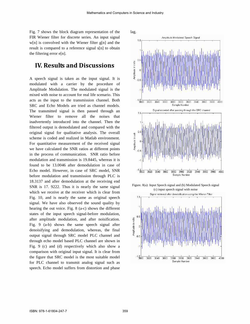
Fig. 7 shows the block diagram representation of the FIR Wiener filter for discrete series. An input signal w[n] is convolved with the Wiener filter g[n] and the result is compared to a reference signal s[n] to obtain the filtering error e[n].
IV. Results and Discussions
A speech signal is taken as the input signal. It is modulated with a carrier by the procedure of Amplitude Modulation. The modulated signal is the mixed with noise to account for real life scenario. This acts as the input to the transmission channel. Both SRC and Echo Models are tried as channel models. The transmitted signal is then passed through an Wiener filter to remove all the noises that inadvertently introduced into the channel. Then the filtered output is demodulated and compared with the original signal for qualitative analysis. The overall scheme is coded and realized in Matlab environment. For quantitative measurement of the received signal we have calculated the SNR ratios at different points in the process of communication. SNR ratio before modulation and transmission is 19.8445, whereas it is found to be 13.0046 after demodulation in case of Echo model. However, in case of SRC model, SNR before modulation and transmission through PLC is 18.3137 and after demodulation at the receiving end SNR is 17. 9222. Thus it is nearly the same signal which we receive at the receiver which is clear from Fig. 10, and is nearly the same as original speech signal. We have also observed the sound quality by hearing the out voice. Fig. 8 (a-c) shows the different states of the input speech signal-before modulation, after amplitude modulation, and after noisification. Fig. 9 (a-b) shows the same speech signal after denoisifying and demodulation, whereas, the final output signal through SRC model PLC channel and through echo model based PLC channel are shown in Fig. 9 (c) and (d) respectively which also show a comparison with original input signal. It is clear from the figure that SRC model is the most suitable model for PLC channel to transmit analog signal such as speech. Echo model suffers from distortion and phase
lag.
Figure. 8(a): Input Speech signal and (b) Modulated Speech signal (c) input speech signal with noise
Mathematics and Computers in Science and Industry
ISBN: 978-1-61804-247-7 359
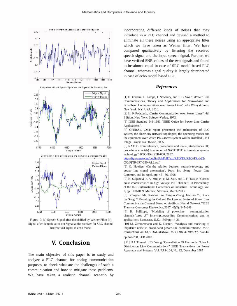
Figure 9: (a) Speech Signal after denoisified by Weiner Filter (b)
Signal after demodulation (c) Signal at the receiver for SRC channel (d) received signal in echo model
V. Conclusion The main objective of this paper is to study and analyze a PLC channel for analog communication purposes, to check what are the challenges of such a communication and how to mitigate these problems. We have taken a realistic channel scenario by
incorporating different kinds of noises that may introduce in a PLC channel and devised a method to eliminate all these noises using an appropriate filter which we have taken as Weiner filter. We have compared qualitatively by listening the received speech signal and the input speech signal. Further, we have verified SNR values of the two signals and found to be almost equal in case of SRC model based PLC channel, whereas signal quality is largely deteriorated in case of echo model based PLC.
References [1] H. Ferreira, L. Lampe, J. Newbury, and T. G. Swart, \Power Line Communications, Theory and Applications for Narrowband and Broadband Communications over Power Lines', John Wiley & Sons, New York, NY, USA, 2010. [2] H. K Podszeck, \Carrier Communication over Power Lines", 4th Edition, New York: Spinger-Verlag, 1972. [3] IEEE Standard 643-1980, \IEEE Guide for Power-Line Carrier Applications". [4] OPERA1, \D44: report presenting the architecture of PLC system, the electricity network topologies, the operating modes and the equipment over which PLC access system will be installed", IST Integr. Project No 507667, 2005. [5] NATO \HF interference, procedures and tools (Interferences HF, procedures et outils) final report of NATO RTO information systems technology", RTO-TR-ISTR-050, 2007, http://ftp.rta.nato.int/public/PubFullText/RTO/TR/RTO-TR-I-ST- 050/$$TR-IST-050-ALL.pdf. [6] O. Hooijen, \On the relation between network-topology and power line signal attenuation", Proc. Int. Symp. Power Line Commun. and Its Appl., pp. 45 - 56, 1998. [7] N. Suljanovi_c, A. Muj_ci_c, M. Zajc, and J. F. Tasi_c, \Corona noise characteristics in high voltage PLC channel", in Proceedings of the IEEE International Conference on Industrial Technology, vol. 2, pp. 10361039, Maribor, Slovenia, March 2003. [8] Yong-tao Ma, Kai-hua Liu, Zhi-jun Zhang, Jie-xiao Yu, Xiao-lin Gong, “ Modeling the Colored Background Noise of Power Line Communication Channel Based on Artificial Neural Network.”IEEE Trans on Consumer Electronics, 2007, 45(2): 345~348 [9] H. Phillipps, “Modeling of powerline communication channels”,proc .3rd Int.symp.power-line Communications and its applications, Lancaster, U.K., 1999,pp.14-21. [10] M. Zimmermann and K. Dostert, “Analysis and modeling of impulsive noise in broad-band power-line communications,” IEEE transactions on ELECTROMAGNETIC COMPATIBILITY, Vol.44,
pp.249-258, FEB 2002.
[11] H.J. Trussell, J.D. Wang “Cancellation Of Harmonic Noise In Distribution Line Communications” IEEE Transactions on Power Apparatus and Systems, Vol. PAS-104, No. 12, December 1985
Mathematics and Computers in Science and Industry
ISBN: 978-1-61804-247-7 360