Embed Size (px)
Citation preview
POWER MANAGEMENT IN HYBRID MICROGRID
USING RENEWABLE SOURCES
Ph.D. Synopsis
submitted to Gujarat Technological University
in
Electrical Engineering
by
KARKAR HITESH MAKANBHAI
(Enrolment No. 139997109004)
Dr. Indrajit N Trivedi (Supervisor)
Professor, Department of Power Electronics,
Vishwakarma Government Engineering College, Chandkheda, Ahmedabad
Dr. Prasanta K Ghosh (Co-Supervisor)
Professor, Electrical Engineering and Computer Science
Center for Science and Technology
Syracuse University, Syracuse, New York, USA
GUJARAT TECHNOLOGICAL UNIVERSITY
AHMEDABAD
2
CONTENTS
1 Abstract…………………………………………………………….. 3
2 State of The Art of The Research Topic………………………….... 4
3 Definition of The Problem…………………………………………. 6
4 Objective and Scope of Work…………………………………….... 6
5 Original Contribution by The Thesis………………………………. 7
6 Methodology of Research, Results / Comparisons……………….... 8
7 Achievements with Respect to Objectives ………………………… 21
8 Conclusion…………………………………………………………. 22
9 Paper Publication…………………………………………………... 23
10 References………………………………………………………….. 24
3
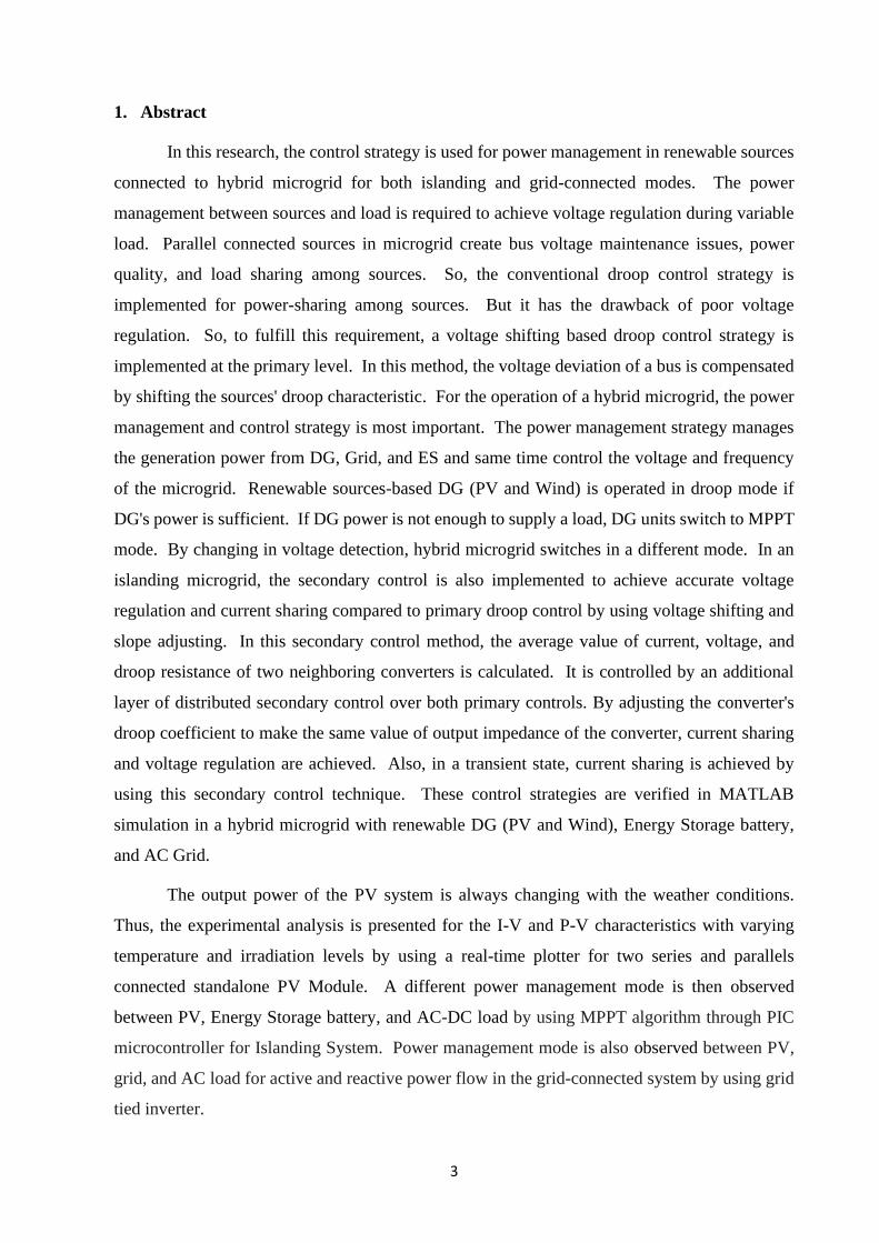
1. Abstract
In this research, the control strategy is used for power management in renewable sources
connected to hybrid microgrid for both islanding and grid-connected modes. The power
management between sources and load is required to achieve voltage regulation during variable
load. Parallel connected sources in microgrid create bus voltage maintenance issues, power
quality, and load sharing among sources. So, the conventional droop control strategy is
implemented for power-sharing among sources. But it has the drawback of poor voltage
regulation. So, to fulfill this requirement, a voltage shifting based droop control strategy is
implemented at the primary level. In this method, the voltage deviation of a bus is compensated
by shifting the sources' droop characteristic. For the operation of a hybrid microgrid, the power
management and control strategy is most important. The power management strategy manages
the generation power from DG, Grid, and ES and same time control the voltage and frequency
of the microgrid. Renewable sources-based DG (PV and Wind) is operated in droop mode if
DG's power is sufficient. If DG power is not enough to supply a load, DG units switch to MPPT
mode. By changing in voltage detection, hybrid microgrid switches in a different mode. In an
islanding microgrid, the secondary control is also implemented to achieve accurate voltage
regulation and current sharing compared to primary droop control by using voltage shifting and
slope adjusting. In this secondary control method, the average value of current, voltage, and
droop resistance of two neighboring converters is calculated. It is controlled by an additional
layer of distributed secondary control over both primary controls. By adjusting the converter's
droop coefficient to make the same value of output impedance of the converter, current sharing
and voltage regulation are achieved. Also, in a transient state, current sharing is achieved by
using this secondary control technique. These control strategies are verified in MATLAB
simulation in a hybrid microgrid with renewable DG (PV and Wind), Energy Storage battery,
and AC Grid.
The output power of the PV system is always changing with the weather conditions.
Thus, the experimental analysis is presented for the I-V and P-V characteristics with varying
temperature and irradiation levels by using a real-time plotter for two series and parallels
connected standalone PV Module. A different power management mode is then observed
between PV, Energy Storage battery, and AC-DC load by using MPPT algorithm through PIC
microcontroller for Islanding System. Power management mode is also observed between PV,
grid, and AC load for active and reactive power flow in the grid-connected system by using grid
tied inverter.
4
2. State of the Art of the Research Topic
Today, non-renewable energy sources like coal, oil, gas, etc., are used worldwide to
produce electrical energy. But these non-renewable energy sources are producing environmental
pollution [1-3]. So, the Distributed Generation (DG) system's importance increases to utilizing
renewable energy sources to produce electricity [4-5]. There are various types of renewable
energy sources (REs) like solar photovoltaic (PV), wind generator, etc., available [6-7]. It is
challenging for renewable energy sources to connect with AC main grid directly. So, a
microgrid's role is very important to interface between DG and grid to connect REs. This
microgrid is a small distribution system with a combination of DG units, energy storage devices
like battery and load. The hybrid microgrid can be operated in islanding and grid-connected
mode [8-10].
In a hybrid microgrid, various sources are connected in parallel with the bus via a power
electronics converter (PEC). So, it creates issues of bus voltage maintenance, power quality, and
load sharing among sources. Hierarchical control is used to solve these issues. It has primary
and secondary control level. The primary control level is used to solve power-sharing among
sources. The secondary control layer is used for voltage compensation and enhancement of
current sharing [11-12]
There are two methods for power sharing among DG in the primary control level: Active
load sharing and Passive load sharing. Active load sharing is further classified into master-slave
control, centralized control, and circular chain current (3C) [13]. The drawback of these methods
is that it requires high bandwidth communication.
A decentralized based passive load sharing method is mostly used to avoid
communication links. It is also called the droop concept. The droop concept's principle is that
the synchronous rotating generator allows changing their power output during the change in load
without a communication link [14-16]. Droop control is widely used in a hybrid microgrid for the
current sharing purpose [17-24]. Due to its reliability, its application in a microgrid is higher [25-
29].
The multiple sources are connected in parallel with a bus, which creates a circulating
current among converter in a hybrid microgrid. For these, there are two solutions. In the first
solution, a resistor is put in series with DG. But it is not possible practically in a real hybrid
microgrid system because it produces high power losses [30]. The second solution is better
applicable in a hybrid microgrid. It is known as a virtual resistance method. This method is
widely used because there is no communication line. Virtual resistance is the ideal value and not
affected by temperature. It will not produce real power losses. This virtual resistance is also
5
called the droop coefficient, droop gain, or droop constant. It is used to suppress circulating
current among converter [31, 32].
In the conventional droop control method, there is a trade-off between load sharing and
voltage regulation. Voltage regulation performance is superior in the case of a small droop
coefficient as compared to the selection of a large droop coefficient. If we select a larger droop
coefficient, current sharing among the converter is fair, but voltage regulation is inferior. It is a
drawback of conventional droop control [33-35].
The main key point is power management in the hybrid microgrid. It means power must
be balanced between renewable energy sources (REs), energy storage devices, grid, and load in
any condition. So, bus voltage also must be maintained at any load. Microgrid should be
operated in a different mode for power management. If power generation is not sufficient by
DG, then extra power will be provided by the islanding mode's storage device. In grid-connected
mode, the grid exchange power to the microgrid as per load requirement [36-39].
The secondary power management strategy is divided into centralized, decentralized, and
hybrid in the islanding mode. The centralized secondary control is also called supervisory control
[40]. Its application in which a centralized layer is suggested to achieve power balance in a
microgrid. The decentralized secondary control is further divided into two methods.: (i) with
communication and (ii) without communication. Communication is required between DG in
decentralized secondary control with communication. In [41] low bandwidth signal is used for
voltage and current information between DG Average current sharing (ACS) communication-
based control is presented in [42]. The drawback of ACS is that load sharing bus has to be
distributed across with power lines inside the microgrid. It can be interjected by the external noise
in the bus. In [43] decentralized communication-based power line singling [PLS] is given. The
drawback of this method is that it has very slow communication. Multi agent-based control system
(MAS) is presented in [44-45]. These are applied using a conjunction of intelligent agent and
real-time control that communicate with each other. In this process, each agent is answerable for
finding the portion of trouble, such as voltage balancing, load priority, and battery charging.
Without communication, mostly the DC bus singling (DBS) method is used [46-49]. When
multiple numbers of sources are used. It is complicated to divide the voltage level of each source.
Hybrid secondary power control gives an accurate result at both levels [50].
Secondary droop control is the proposed solution for voltage regulation and current sharing
accuracy to solve the islanded microgrid problem [51- 58]. The summary of the existing method
of secondary control is in [51-55]. The issue of single-point failure is given in [51]. There is no
problem with single-point failure, but current sharing accuracy is only achieved by selecting a large
6
droop coefficient in [52]. The current sharing and voltage regulation are good in [53], but its
performance is very poor in dynamic condition. In [54-55], performance is good in dynamic
condition, but it has more complexity for implementation.
Power management is also required in grid-connected microgrid [59-60]. There is surplus
power generation in the microgrid; extra power will be transfer to the grid [61-62]. Power shall be
transferred back to the microgrid due to overload [63]. So, the droop control strategy is used in the
grid converter for power-sharing with the AC grid. There are various control techniques for power-
sharing for power management and voltage regulation in grid-connected mode [64-68]. In [64]
the frequency deviation is very high. The communication channel is required in [65]. In [66]
separated controller is needed. Accurate power-sharing is difficult at a high gain in [67]. The
system becomes more costly in [68].
3. Definition of The Problem
With this background, this research is focused on the power management strategy of a hybrid
microgrid. In power management of hybrid microgrid for standalone and grid-connected mode,
generation power must be equal to load power by controlling renewable energy sources and
converter. For this purpose, the voltage regulation of the bus is also required. Proportional current
sharing is a significant issue due to the number of sources that are connected by a bus. A
conventional droop control method is implemented in primary control by most of the researchers.
So, in this method, the selection of a droop coefficient is essential. But by selecting a higher droop
coefficient, there is a problem of poor voltage regulation. It is a limitation of conventional primary
droop control. To solve this limitation of conventional primary droop control, another control
strategy to be found to improve the voltage regulation of the hybrid microgrid. Some researchers
have also implemented secondary control, but its performance is inferior in dynamic conditions
during a fast change in load. So, some other control strategy is to be implemented at the primary
and secondary level for proper load sharing among sources, improve the voltage regulation and
current sharing accuracy in the hybrid microgrid.
4. Objective and Scope of Work
The objective of the research is as per following.
To develop a control strategy for power management to maintain the power balance and
stable operation of hybrid microgrid under variable load conditions by combining
renewable sources, energy storage devices, and utility in islanding (standalone) and grid-
connected mode. Further, this control scheme will also be useful for proper load sharing
among the bus's source and voltage restoration.
7
To achieve above the objective, the scope of work includes:
• To investigate the drawback of a conventional control strategy as per the literature survey
and improve the performance at the primary and secondary level for proper load sharing.
• To simulate the microgrid with two DG for primary and secondary droop control for
accurate current sharing and voltage regulation.
• To simulate a hybrid microgrid with MPPT and AC droop control and evaluate its
operation to propose a power management mode then implement a proposed power
management algorithm in renewable-based DG (PV & Wind), Battery, and Grid for
power balance between source and load in a hybrid microgrid.
• To compare real-time parameter in single, series, and parallel-connected PV module at a
different temperature, irradiation, and partially shaded using MPPT control.
• To evaluate experimental performance for the different modes of power management in
a standalone and grid-connected system.
5. Original Contribution by the Thesis
• Power management's control strategy is implemented to maintain a power balance in a hybrid
microgrid under different operating conditions. Furthermore, the balanced power state of a
hybrid microgrid can be decided by bus voltage changing.
• For power management in a hybrid microgrid, both MPPT and droop modules are
implemented in DG (PV and Wind). A droop control strategy is implemented to achieve
proper load sharing. DG is operated in droop mode if its power is sufficient. If DG power
is not enough for load, PV and wind units switch to maximum power tracking mode.
During switching between MPPT and droop module, it produces unfavorable transient. So
seamless control strategy is implemented in the DG unit to avoid transient.
• Q-V and P-Q droop control are also implemented in VSC based interlinking bidirectional
converter to balance the power between grid and microgrid.
• For proportional power-sharing, the selection of the virtual droop coefficient is essential. But
by selecting a higher droop coefficient, there is a problem of poor voltage regulation. During
higher load, the voltage of the bus is reduced. There is a limitation of the conventional droop
control method in primary control. For that purpose, the first voltage deviation (∆𝑣) produces
by conventional droop control is sensed. Then ∆𝑣 is adding in the conventional primary loop.
8
So, the droop curve position is shifted after adding ∆𝑣. This proposed voltage shifting based
droop control is implemented at the primary level.
• There is three PI controller used in the secondary control technique. In secondary control,
its performance is right in the dynamic condition under fast-changing in load. The
secondary control first controller is used to restore voltage deviation in each converter
produced proposed primary control, and another both controllers work together and
regulate droop coefficients separately. So, the output impedance of each converter would
be the same.
• By experimental analysis, prototype series and parallel PV modules are tested under
different temperatures and radiation. Then, by observing the different real-time parameters,
maintaining a power balance between PV, Battery, DC and AC load in various modes using
the MPPT algorithm in the PIC microcontroller. Also, by control of grid-tied solar inverter,
the active and reactive power balance is maintained between PV, Grid, and load.
6. Methodology of Research, Results / Comparisons
6.1 System Configuration
Pn Qn Vn fn
PV
WIND
DC-DCBoost
ConverterRectifier
DC-DCBoost
Converter
DC-DCBidirectional
Converter
BatteryAC-DC
Bidirectional
Converter
AC Grid
PWMDroop
Control
DC Bus
AC BusLoad
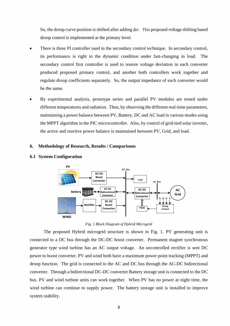
Fig. 1 Block Diagram of Hybrid Microgrid
The proposed Hybrid microgrid structure is shown in Fig. 1. PV generating unit is
connected to a DC bus through the DC-DC boost converter. Permanent magnet synchronous
generator type wind turbine has an AC output voltage. An uncontrolled rectifier is sent DC
power to boost converter. PV and wind both have a maximum power point tracking (MPPT) and
droop function. The grid is connected to the AC and DC bus through the AC-DC bidirectional
converter. Through a bidirectional DC-DC converter Battery storage unit is connected to the DC
bus. PV and wind turbine units can work together. When PV has no power at night time, the
wind turbine can continue to supply power. The battery storage unit is installed to improve
system stability.
9
This microgrid is connected to the AC main grid through a bidirectional DC-AC
converter. The power flow in both directions. It is a VSC based bidirectional converter. The
droop control strategy is used to control the bidirectional power flow. This system is allowed
for voltage regulation and power-sharing using droop control. The parameter of the proposed
hybrid microgrid is as per below.
Power output of Photovoltaic array (PV) generation system (DG 1) – 10 KW.
Power output of Wind generation system (DG 2) – 8.5 KW
Power output of ES System – 5 KW, Maximum output power of AC Grid – 10 KW.
Load – 20 KW Rated DC bus Voltage – 400 V
6.2 Operation Mode of Power Management
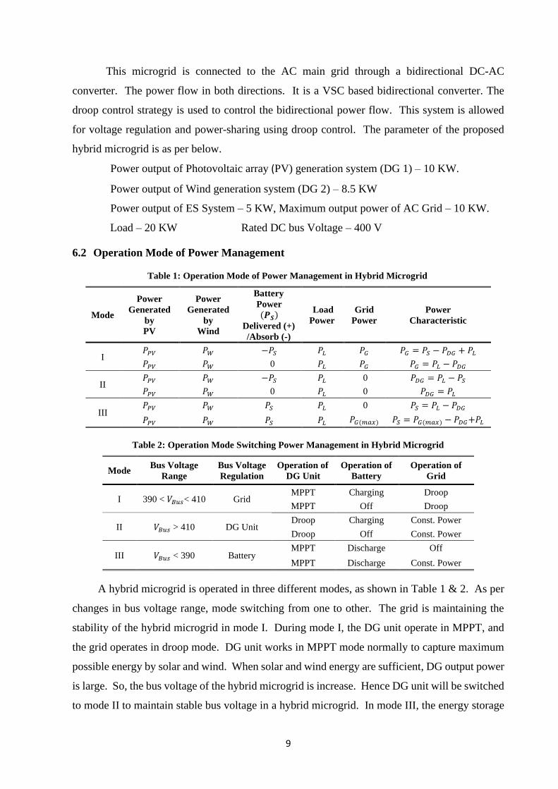
Table 1: Operation Mode of Power Management in Hybrid Microgrid
Mode
Power
Generated
by
PV
Power
Generated
by
Wind
Battery
Power (𝑷𝑺)
Delivered (+)
/Absorb (-)
Load
Power
Grid
Power
Power
Characteristic
I 𝑃𝑃𝑉 𝑃𝑊 −𝑃𝑆 𝑃𝐿 𝑃𝐺 𝑃𝐺 = 𝑃𝑆 − 𝑃𝐷𝐺 + 𝑃𝐿
𝑃𝑃𝑉 𝑃𝑊 0 𝑃𝐿 𝑃𝐺 𝑃𝐺 = 𝑃𝐿 − 𝑃𝐷𝐺
II 𝑃𝑃𝑉 𝑃𝑊 −𝑃𝑆 𝑃𝐿 0 𝑃𝐷𝐺 = 𝑃𝐿 − 𝑃𝑆
𝑃𝑃𝑉 𝑃𝑊 0 𝑃𝐿 0 𝑃𝐷𝐺 = 𝑃𝐿
III 𝑃𝑃𝑉 𝑃𝑊 𝑃𝑆 𝑃𝐿 0 𝑃𝑆 = 𝑃𝐿 − 𝑃𝐷𝐺
𝑃𝑃𝑉 𝑃𝑊 𝑃𝑆 𝑃𝐿 𝑃𝐺(𝑚𝑎𝑥) 𝑃𝑆 = 𝑃𝐺(𝑚𝑎𝑥) − 𝑃𝐷𝐺+𝑃𝐿
Table 2: Operation Mode Switching Power Management in Hybrid Microgrid
Mode Bus Voltage
Range
Bus Voltage
Regulation
Operation of
DG Unit
Operation of
Battery
Operation of
Grid
I 390 < 𝑉𝐵𝑢𝑠< 410 Grid MPPT Charging Droop
MPPT Off Droop
II 𝑉𝐵𝑢𝑠 > 410 DG Unit Droop Charging Const. Power
Droop Off Const. Power
III 𝑉𝐵𝑢𝑠 < 390 Battery MPPT Discharge Off
MPPT Discharge Const. Power
A hybrid microgrid is operated in three different modes, as shown in Table 1 & 2. As per
changes in bus voltage range, mode switching from one to other. The grid is maintaining the
stability of the hybrid microgrid in mode I. During mode I, the DG unit operate in MPPT, and
the grid operates in droop mode. DG unit works in MPPT mode normally to capture maximum
possible energy by solar and wind. When solar and wind energy are sufficient, DG output power
is large. So, the bus voltage of the hybrid microgrid is increase. Hence DG unit will be switched
to mode II to maintain stable bus voltage in a hybrid microgrid. In mode III, the energy storage
10
battery is maintaining the stability of the hybrid microgrid. It operating in droop mode under
discharging condition.
6.3 Droop Control Strategy
In a microgrid, the sources are connected in parallel. So, the droop control strategy is used
to avoid circulating current and proportional current sharing among source. The droop control
is put to each source. It is a decentralized method, so there is no need for communication between
sources.
6.3.1 Conventional Primary Droop Control Strategy
There are two loops in the conventional droop control strategy for the DC-DC converter.
There is the droop control, inner current control loop and outer control loop in these units. The
current inner loop can improve the response speed. The basic equation of conventional primary
droop control is expressed by equation (i).
𝑣𝑖 = 𝑣𝑟𝑒𝑓 − 𝑖𝑖𝑟𝑑𝑖………. (i)
Where 𝑣𝑟𝑒𝑓 = Reference voltage of converter, 𝑣𝑖= Local output voltage of 𝑖𝑡ℎ converter
after applied droop loop, 𝑟𝑑𝑖 = Droop Resistance, 𝑖𝑖 = Output current of the converter.
The conventional droop control is used in a hybrid microgrid for proper current sharing
among converter. But there is a trade-off between current sharing and voltage regulation in
conventional primary droop control. This is the drawback of the conventional primary droop
control strategy.
6.3.2 Voltage Shifting Based Primary Droop Control Strategy
In a hybrid microgrid, a conventional droop control strategy is easy to implement but
poor voltage regulation. So voltage shifting based proposed primary droop control, in which ∆𝑣
is added to them with a reference voltage of the converter to regulate the bus voltage.
𝒗
𝒊 𝒊𝟐
∆𝒗𝟏
∆𝒗𝟐
Voltage Shifting Based
Primary Droop Control
𝒊𝟏
ConventionalPrimary Droop
Control
𝒂
𝒃
𝒃′ 𝒓𝒅𝟏
𝒓𝒅𝟐
𝒗𝟐
𝒗𝟏
𝒂′ 𝒗𝒓𝒆𝒇
𝒊𝟏′ 𝒊𝟐
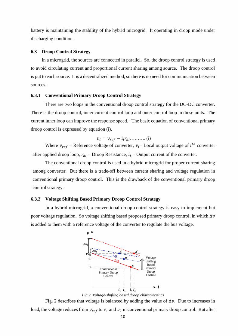
′ Fig 2. Voltage-shifting based droop characteristics
Fig. 2 describes that voltage is balanced by adding the value of ∆𝑣. Due to increases in
load, the voltage reduces from 𝑣𝑟𝑒𝑓 to 𝑣1 and 𝑣2 in conventional primary droop control. But after
11
adding ∆𝑣1 and ∆𝑣2 , shifting the droop curve line from a to a' and b to b' respectively. So,
voltage shifting based proposed primary droop control generates a new voltage reference value
(𝑣𝑖∗) of the local converter unit by shifting the drooping line, regulating the voltage of the
converter at normal value. The voltage shifting based primary droop control is expressed by
equation (ii).
𝑣𝑖∗ = 𝑣𝑟𝑒𝑓 − 𝑖𝑖𝑟𝑑𝑖 + ∆𝑣𝑖………. (ii)
PI PI PWMDC-DC
Converter
+
+-
+
+
-
-𝒗𝒓𝒆𝒇
∆𝒗𝒊
𝒗𝒊∗
𝒗𝟎
𝒊𝒊 𝒓𝒅𝒊
Fig. 3 Control diagram of Conventional primary droop control technique
The voltage shifting based primary droop control strategy of the DC-DC converter unit
is shown in Fig 3. It consists of a droop control loop, inner voltage loop, and inner current loop
and ∆𝑣. The new reference value of voltage 𝑣∗ is generated by adding ∆𝑣 in a conventional droop
control loop. 𝑣∗ is compared with 𝑣0. Its result is sent to the PI regulator and generates PWM
signals to the boost converter unit.
Here fixes the value of droop resistance is used in each converter. So, the total impedance
of the converter would be unequal. So dynamic performance under a fast change in load current
is poor. It is a limitation of voltage shifting based on the proposed primary droop control.
6.3.3 Secondary Droop Control Strategy
DG
UNIT#1
PWMVoltage
Loop
DC/DC
Converter-1
PI
PI
PI
Current Loop
+
+
+-
-
- ++
-
++
- -
+
-
DC Bus
++
DG
UNIT#2
PWMVoltage
Loop
DC/DC
Converter-2
PI
PI
PI
Current Loop
+
+
+-
-
- ++
-
++
- -
+
-+
+
++
++
++
++
++
++
Conventional Primary Control
Voltage
Shifting
Based
Primary
Control
Secondary Control
Load
+
-
+ -
+
-
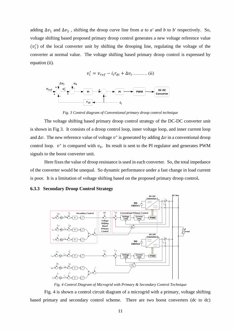
Fig. 4 Control Diagram of Microgrid with Primary & Secondary Control Technique
Fig. 4 is shown a control circuit diagram of a microgrid with a primary, voltage shifting
based primary and secondary control scheme. There are two boost converters (dc to dc)
12
connected in parallel with a common load bus. In the primary control scheme voltage loop, the
current loop and droop coefficient loop are used. In voltage shifting based primary control
scheme, ∆𝑣1 and ∆𝑣2 are added in each converter over conventional primary control.
In this secondary control strategy, the average value calculation of voltage, current, and
droop coefficients of the neighboring converter by three PI controllers. The average voltage
controller compensates the voltage deviation over-voltage shifting based primary control by
producing the voltage shifting value. So, it regulated the output voltage of the converter.
Average current and droop coefficient controllers are used for droop curve adjusting by
adaptively controlling each converter's local droop coefficient. Using both current compensating
and droop coefficient controller control, two converters' output impedance is the same. So, its
performance is good in the dynamic condition under fast-changing in load.
In secondary control, voltage regulation and current sharing is achieved accurately. This
secondary control has enhanced dynamic behavior under variable load conditions.
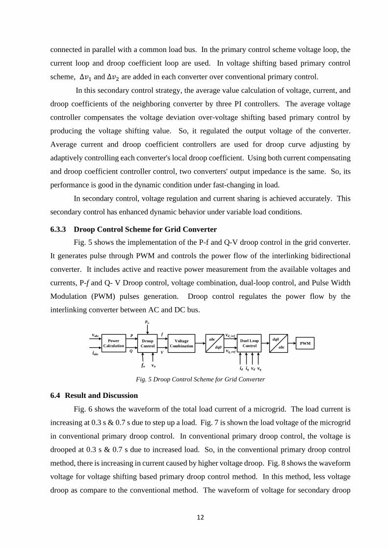
6.3.3 Droop Control Scheme for Grid Converter
Fig. 5 shows the implementation of the P-f and Q-V droop control in the grid converter.
It generates pulse through PWM and controls the power flow of the interlinking bidirectional
converter. It includes active and reactive power measurement from the available voltages and
currents, P-f and Q- V Droop control, voltage combination, dual-loop control, and Pulse Width
Modulation (PWM) pulses generation. Droop control regulates the power flow by the
interlinking converter between AC and DC bus.
Power
Calculation
Droop
Control
Voltage
Combination
Duel Loop
ControlPWM
abc
dq0
dq0
abc
vabc
iabc
P
Q
Pn
fn vn
f
V
id iq vqvd
vd_ref
vq_ref
Fig. 5 Droop Control Scheme for Grid Converter
6.4 Result and Discussion
Fig. 6 shows the waveform of the total load current of a microgrid. The load current is
increasing at 0.3 s & 0.7 s due to step up a load. Fig. 7 is shown the load voltage of the microgrid
in conventional primary droop control. In conventional primary droop control, the voltage is
drooped at 0.3 s & 0.7 s due to increased load. So, in the conventional primary droop control
method, there is increasing in current caused by higher voltage droop. Fig. 8 shows the waveform
voltage for voltage shifting based primary droop control method. In this method, less voltage
droop as compare to the conventional method. The waveform of voltage for secondary droop
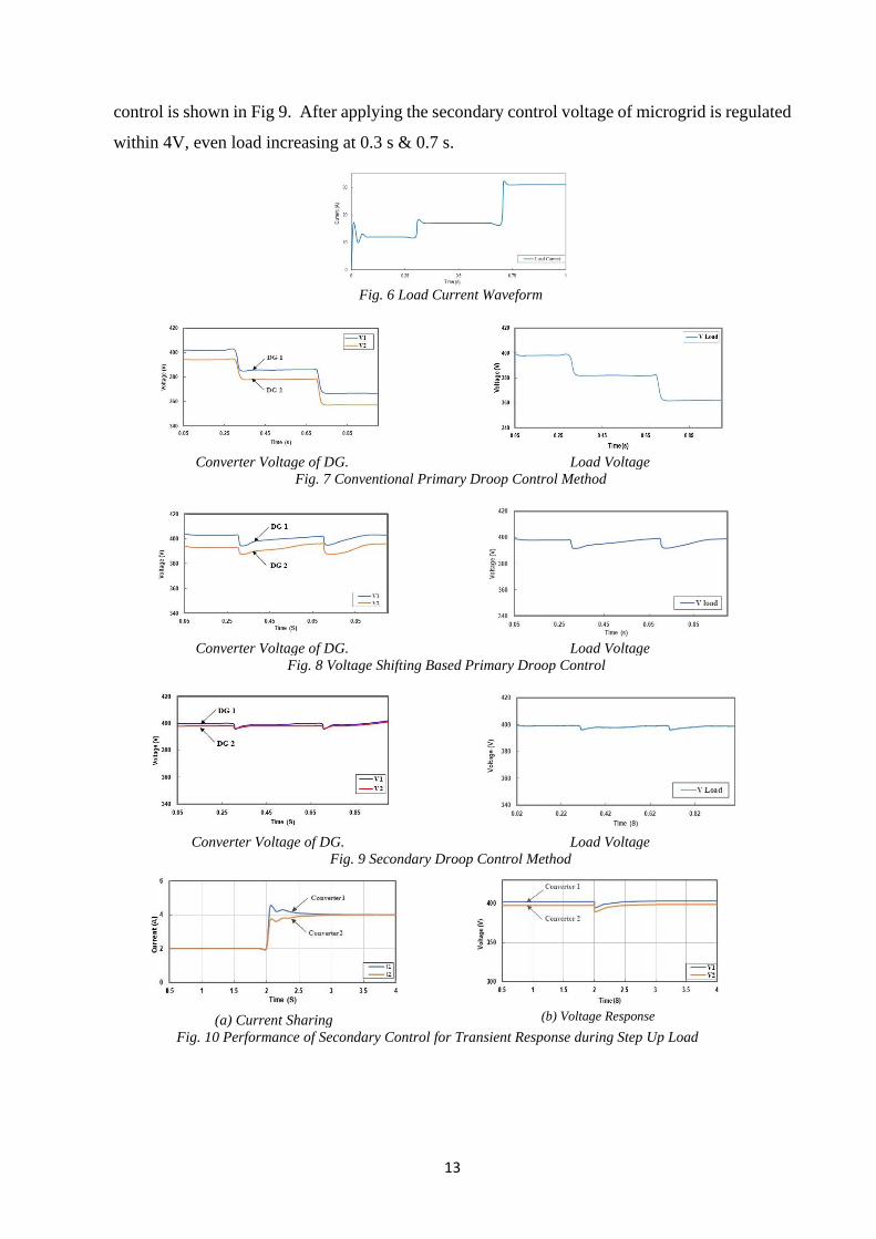
13
control is shown in Fig 9. After applying the secondary control voltage of microgrid is regulated
within 4V, even load increasing at 0.3 s & 0.7 s.
Fig. 6 Load Current Waveform
Converter Voltage of DG.
Load Voltage
Fig. 7 Conventional Primary Droop Control Method
Converter Voltage of DG.
Load Voltage
Fig. 8 Voltage Shifting Based Primary Droop Control
Converter Voltage of DG.
Load Voltage
Fig. 9 Secondary Droop Control Method
(a) Current Sharing
(b) Voltage Response
Fig. 10 Performance of Secondary Control for Transient Response during Step Up Load
14
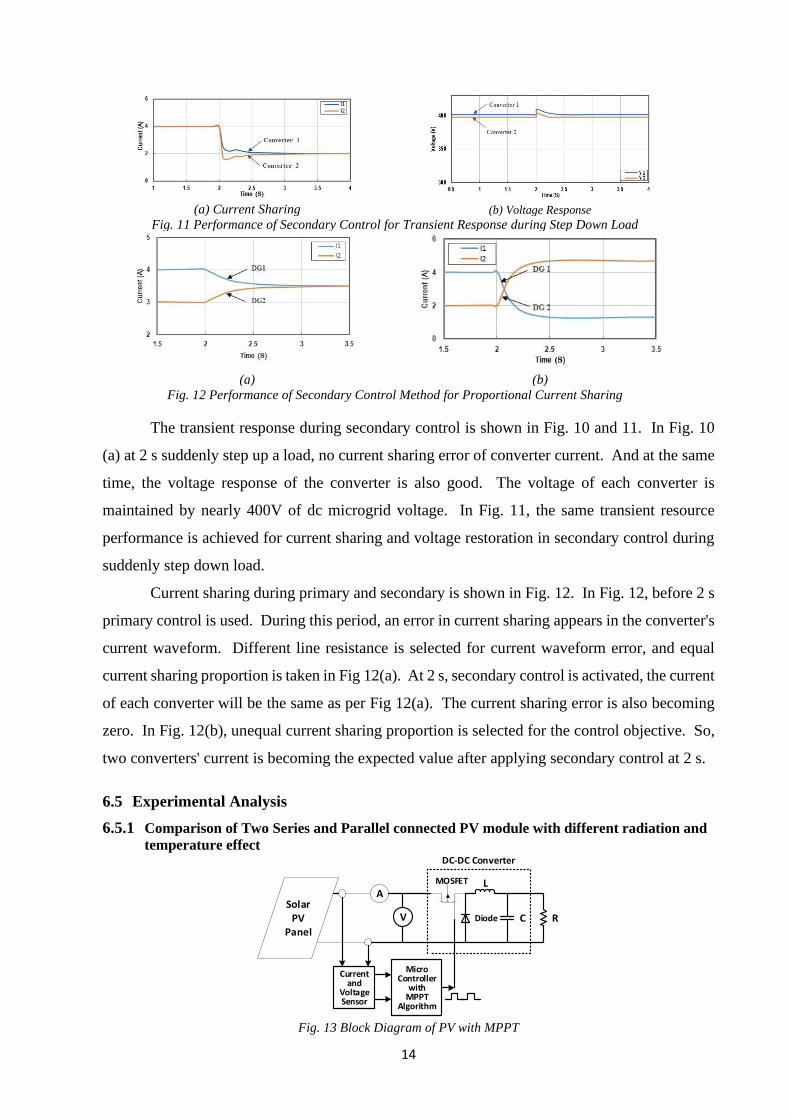
(a) Current Sharing
(b) Voltage Response
Fig. 11 Performance of Secondary Control for Transient Response during Step Down Load
(a)
(b)
Fig. 12 Performance of Secondary Control Method for Proportional Current Sharing
The transient response during secondary control is shown in Fig. 10 and 11. In Fig. 10
(a) at 2 s suddenly step up a load, no current sharing error of converter current. And at the same
time, the voltage response of the converter is also good. The voltage of each converter is
maintained by nearly 400V of dc microgrid voltage. In Fig. 11, the same transient resource
performance is achieved for current sharing and voltage restoration in secondary control during
suddenly step down load.
Current sharing during primary and secondary is shown in Fig. 12. In Fig. 12, before 2 s
primary control is used. During this period, an error in current sharing appears in the converter's
current waveform. Different line resistance is selected for current waveform error, and equal
current sharing proportion is taken in Fig 12(a). At 2 s, secondary control is activated, the current
of each converter will be the same as per Fig 12(a). The current sharing error is also becoming
zero. In Fig. 12(b), unequal current sharing proportion is selected for the control objective. So,
two converters' current is becoming the expected value after applying secondary control at 2 s.
6.5 Experimental Analysis
6.5.1 Comparison of Two Series and Parallel connected PV module with different radiation and
temperature effect
SolarPV
Panel
A
Current and
Voltage Sensor
MicroController
with MPPT
Algorithm
MOSFET
CDiode
L
V R
DC-DC Converter
Fig. 13 Block Diagram of PV with MPPT
15
A Solar PV panel is connected to the DC-DC converter, and PIC microcontroller with
MPPT is shown in figure 13. Perturb and observe (P&O) algorithm is applied in the PIC
microcontroller. The digital meters and data logger/plotter by connecting the Logger Plotter Box
with module output are used for taking readings. The values of current and voltages can be taken
from the data logger, and then the I-V curve can be plotted at different radiation and temperature
levels. The Real-time plotter, which will plot the curve of I-V and P-V.
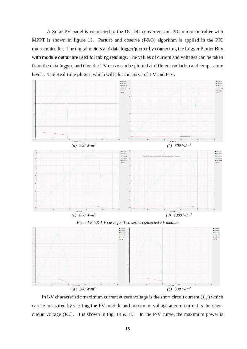
(a) 200 W/m2 (b) 600 W/m2
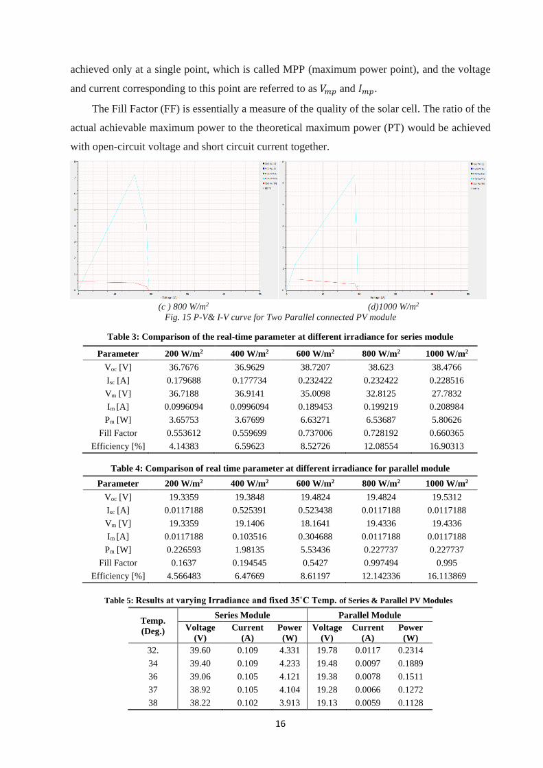
(c) 800 W/m2 (d) 1000 W/m2
Fig. 14 P-V& I-V curve for Two series connected PV module
(a) 200 W/m2 (b) 600 W/m2
In I-V characteristic maximum current at zero voltage is the short circuit current (𝐼𝑠𝑐) which
can be measured by shorting the PV module and maximum voltage at zero current is the open-
circuit voltage (𝑉𝑜𝑐). It is shown in Fig. 14 & 15. In the P-V curve, the maximum power is
16
achieved only at a single point, which is called MPP (maximum power point), and the voltage
and current corresponding to this point are referred to as 𝑉𝑚𝑝 and 𝐼𝑚𝑝.
The Fill Factor (FF) is essentially a measure of the quality of the solar cell. The ratio of the
actual achievable maximum power to the theoretical maximum power (PT) would be achieved
with open-circuit voltage and short circuit current together.
(c ) 800 W/m2 (d)1000 W/m2
Fig. 15 P-V& I-V curve for Two Parallel connected PV module
Table 3: Comparison of the real-time parameter at different irradiance for series module
Table 4: Comparison of real time parameter at different irradiance for parallel module
Table 5: Results at varying Irradiance and fixed 35˚C Temp. of Series & Parallel PV Modules
Temp.
(Deg.)
Series Module Parallel Module
Voltage
(V)
Current
(A)
Power
(W)
Voltage
(V)
Current
(A)
Power
(W)
32. 39.60 0.109 4.331 19.78 0.0117 0.2314
34 39.40 0.109 4.233 19.48 0.0097 0.1889
36 39.06 0.105 4.121 19.38 0.0078 0.1511
37 38.92 0.105 4.104 19.28 0.0066 0.1272
38 38.22 0.102 3.913 19.13 0.0059 0.1128
Parameter 200 W/m2 400 W/m2 600 W/m2 800 W/m2 1000 W/m2
Voc [V] 36.7676 36.9629 38.7207 38.623 38.4766
Isc [A] 0.179688 0.177734 0.232422 0.232422 0.228516
Vm [V] 36.7188 36.9141 35.0098 32.8125 27.7832
Im [A] 0.0996094 0.0996094 0.189453 0.199219 0.208984
Pm [W] 3.65753 3.67699 6.63271 6.53687 5.80626
Fill Factor 0.553612 0.559699 0.737006 0.728192 0.660365
Efficiency [%] 4.14383 6.59623 8.52726 12.08554 16.90313
Parameter 200 W/m2 400 W/m2 600 W/m2 800 W/m2 1000 W/m2
Voc [V] 19.3359 19.3848 19.4824 19.4824 19.5312
Isc [A] 0.0117188 0.525391 0.523438 0.0117188 0.0117188
Vm [V] 19.3359 19.1406 18.1641 19.4336 19.4336
Im [A] 0.0117188 0.103516 0.304688 0.0117188 0.0117188
Pm [W] 0.226593 1.98135 5.53436 0.227737 0.227737
Fill Factor 0.1637 0.194545 0.5427 0.997494 0.995
Efficiency [%] 4.566483 6.47669 8.61197 12.142336 16.113869
17
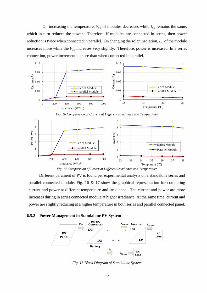
On increasing the temperature, 𝑉𝑜𝑐 of modules decreases while 𝐼𝑠𝑐 remains the same,
which in turn reduces the power. Therefore, if modules are connected in series, then power
reduction is twice when connected in parallel. On changing the solar insolation, 𝐼𝑠𝑐 of the module
increases more while the 𝑉𝑜𝑐 increases very slightly. Therefore, power is increased. In a series
connection, power increment is more than when connected in parallel.
Fig. 16 Comparision of Current at Different Irradiance and Temperature
Fig. 17 Comparision of Power at Different Irradiance and Temperature
Different parament of PV is found per experimental analysis on a standalone series and
parallel connected module. Fig. 16 & 17 show the graphical representation for comparing
current and power at different temperature and irradiance. The current and power are more
increases during in series connected module at higher irradiance. At the same time, current and
power are slightly reducing at a higher temperature in both series and parallel connected panel.
6.5.2 Power Management in Standalone PV System
PAC Load
PDC Load
PVPanel
DC
Load
Inverter
DC
DC
DC
AC
AC
Load
Battery
DC-DC ConverterPPV
PS
PInverter
Fig. 18 Block Diagram of Standalone System
0
0.03
0.06
0.09
0.12
0 200 400 600 800 1000
Cu
rren
t (A
)
Irradiance (W/m2)
Series Modulel
Parallel Module
0
0.03
0.06
0.09
0.12
32 34 36 38
Cu
rren
t (A
)
Temprature (ºC)
Series Module
Parallel Module
0
1
2
3
4
5
0 200 400 600 800 1000
Po
wer
(W
)
Irradiance (W/m2)
Series Module
Parallel Module
0
1
2
3
4
5
32 33 34 35 36 37 38
Po
wer
(W
)
Temprature (ºC)
Series Module
Parallel Module
18
A standalone PV system is the one that be used for the locations where grid connectivity
is not present, and these systems fulfil the requirements of these locations. As per fig. 18, this
system consists of PV module, controller with MPPT algorithm, Energy storage battery system,
DC load, inverter, and AC load. The controller regulates the module voltage required by the
battery bank or load and then powered the load. The different operation mode of power
management is given in table 6.
Table 6: Operation Mode of Power Management in Standalone PV System
Mode
Power
Generated
by PV
Battery Power
(PS.)
Released (+)
/Absorb (-)
Power
Delivered to
DC Load
(PDC Load)
Power
Delivered to
AC Load
(PAC Load)
Power
Characteristic
I PPV - Ps PDC Load -- PPV = Ps+ PDC Load
PPV Ps PDC Load -- PPV = PDC Load -Ps
II PPV - Ps -- PInverter PPV = Ps+ PInverter
PPV Ps -- PInverter PPV = PInverter - Ps
III PPV -Ps PDC Load PInverter PPV = Ps+ PDC Load+ PInverter
PPV Ps PDC Load PInverter PPV = PAC Load- PDC Load- PInverter
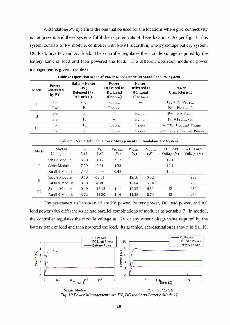
Table 7: Result Table for Power Management in Standalone PV System
Mode Module
Configuration
PPV
(W)
PS.
(W)
PDC Load
(W)
PInverter
(W)
PAC Load
(W)
D.C. Load
Voltage(V)
A.C. Load
Voltage (V)
I
Single Module 3.60 1.17 2.13 12.1
Series Module 7.20 2.01 4.33 12.1
Parallel Module 7.42 2.59 4.43 12.2
II Single Module 0.19 -12.31 12.10 6.52 230
Parallel Module 3.78 -8.80 12.64 6.74 230
III Single Module 0.19 -16.15 4.11 12.32 6.52 12 230
Parallel Module 3.72 -12.39 4.16 11.88 6.74 12 230
The parameters to be observed are PV power, Battery power, DC load power, and AC
load power with different series and parallel combinations of modules as per table 7. In mode I,
the controller regulates the module voltage at 12V or any other voltage value required by the
battery bank or load and then powered the load. Its graphical representation is shown in fig. 19.
Single Module Parallel Module Fig. 19 Power Management with PV, DC load and Battery (Mode 1)
0
1
2
3
4
5
0 0.2 0.4 0.6 0.8 1
Po
wer
(W
)
Time (S)
PV PowerDC Load PowerBattery Power
0
2
4
6
8
10
0 0.2 0.4 0.6 0.8 1
Po
wer
(W
)
Time (S)
PV PowerDC Load PowerBattery Power
19
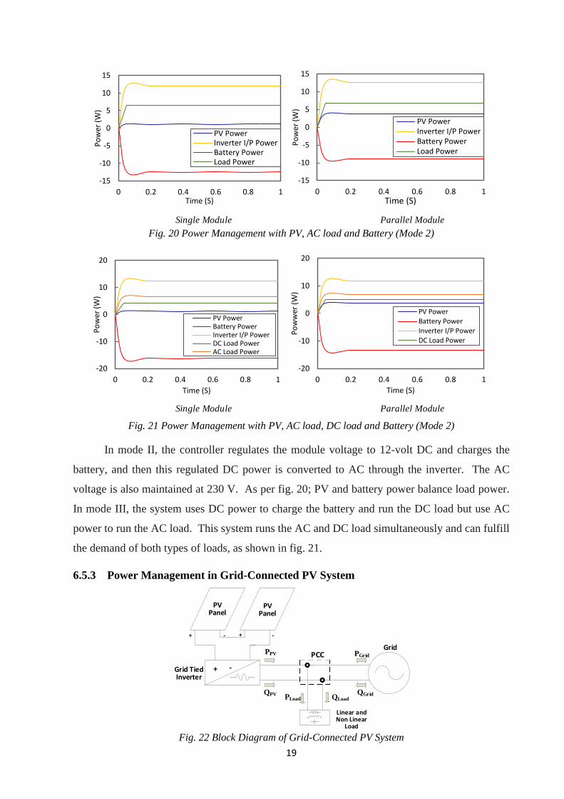
Single Module Parallel Module
Fig. 20 Power Management with PV, AC load and Battery (Mode 2)
Single Module Parallel Module
Fig. 21 Power Management with PV, AC load, DC load and Battery (Mode 2)
In mode II, the controller regulates the module voltage to 12-volt DC and charges the
battery, and then this regulated DC power is converted to AC through the inverter. The AC
voltage is also maintained at 230 V. As per fig. 20; PV and battery power balance load power.
In mode III, the system uses DC power to charge the battery and run the DC load but use AC
power to run the AC load. This system runs the AC and DC load simultaneously and can fulfill
the demand of both types of loads, as shown in fig. 21.
6.5.3 Power Management in Grid-Connected PV System
+ +- -
+ -
PV Panel
PV Panel
Grid Tied Inverter
Linear and Non Linear
Load
GridPCC PGrid
QGrid
PPV
QPVPLoad QLoad
Fig. 22 Block Diagram of Grid-Connected PV System
-15
-10
-5
0
5
10
15
0 0.2 0.4 0.6 0.8 1
Po
wer
(W
)
Time (S)
PV PowerInverter I/P PowerBattery PowerLoad Power
-15
-10
-5
0
5
10
15
0 0.2 0.4 0.6 0.8 1
Po
wer
(W
)
Time (S)
PV PowerInverter I/P PowerBattery PowerLoad Power
-20
-10
0
10
20
0 0.2 0.4 0.6 0.8 1
Po
wer
(W
)
Time (S)
PV PowerBattery PowerInverter I/P PowerDC Load PowerAC Load Power
-20
-10
0
10
20
0 0.2 0.4 0.6 0.8 1
Po
ww
er (
W)
Time (S)
PV Power
Battery Power
Inverter I/P Power
DC Load Power
20
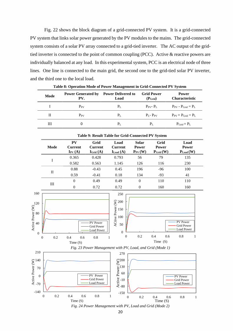
Fig. 22 shows the block diagram of a grid-connected PV system. It is a grid-connected
PV system that links solar power generated by the PV modules to the mains. The grid-connected
system consists of a solar PV array connected to a grid-tied inverter. The AC output of the grid-
tied inverter is connected to the point of common coupling (PCC). Active & reactive powers are
individually balanced at any load. In this experimental system, PCC is an electrical node of three
lines. One line is connected to the main grid, the second one to the grid-tied solar PV inverter,
and the third one to the local load.
Table 8: Operation Mode of Power Management in Grid-Connected PV System
Mode Power Generated by
PV.
Power Delivered to
Load
Grid Power
(PGrid)
Power
Characteristic
I PPV PL PPV- PL PPV - PGrid = PL
II PPV PL PL- PPV PPV + PGrid = PL
III 0 PL PL PGrid = PL
Table 9: Result Table for Grid-Connected PV System
Mode
PV
Current
IPV (A)
Grid
Current
IGrid (A)
Load
Current
ILoad (A)
Solar
Power
PPV (W)
Grid
Power
PGrid (W)
Load
Power
PLoad (W)
I 0.365 0.428 0.793 56 79 135
0.582 0.563 1.145 126 116 230
II 0.88 -0.43 0.45 196 -96 100
0.59 -0.41 0.18 134 -93 41
III 0 0.49 0.49 0 110 110
0 0.72 0.72 0 160 160
Fig. 23 Power Management with PV, Load, and Grid (Mode 1)
Fig. 24 Power Management with PV, Load and Grid (Mode 2)
0
40
80
120
160
0 0.2 0.4 0.6 0.8 1
Act
ive
Po
wer
(W
)
Time (S)
PV Power
Grid Power
Load Power0
50
100
150
200
250
0 0.2 0.4 0.6 0.8 1
AC
tive
Po
wer
(W
)
Time (S)
PV Power
Grid Power
Load Power
-140
-70
0
70
140
210
0 0.2 0.4 0.6 0.8 1
Act
ive
Po
wer
(W
)
Time (S)
PV Power
Grid Power
Load Power
-150
-80
-10
60
130
200
270
0 0.2 0.4 0.6 0.8 1
Act
ive
Po
wer
(W
)
Time (S)
PV PowerGrid PowerLoad Power
21
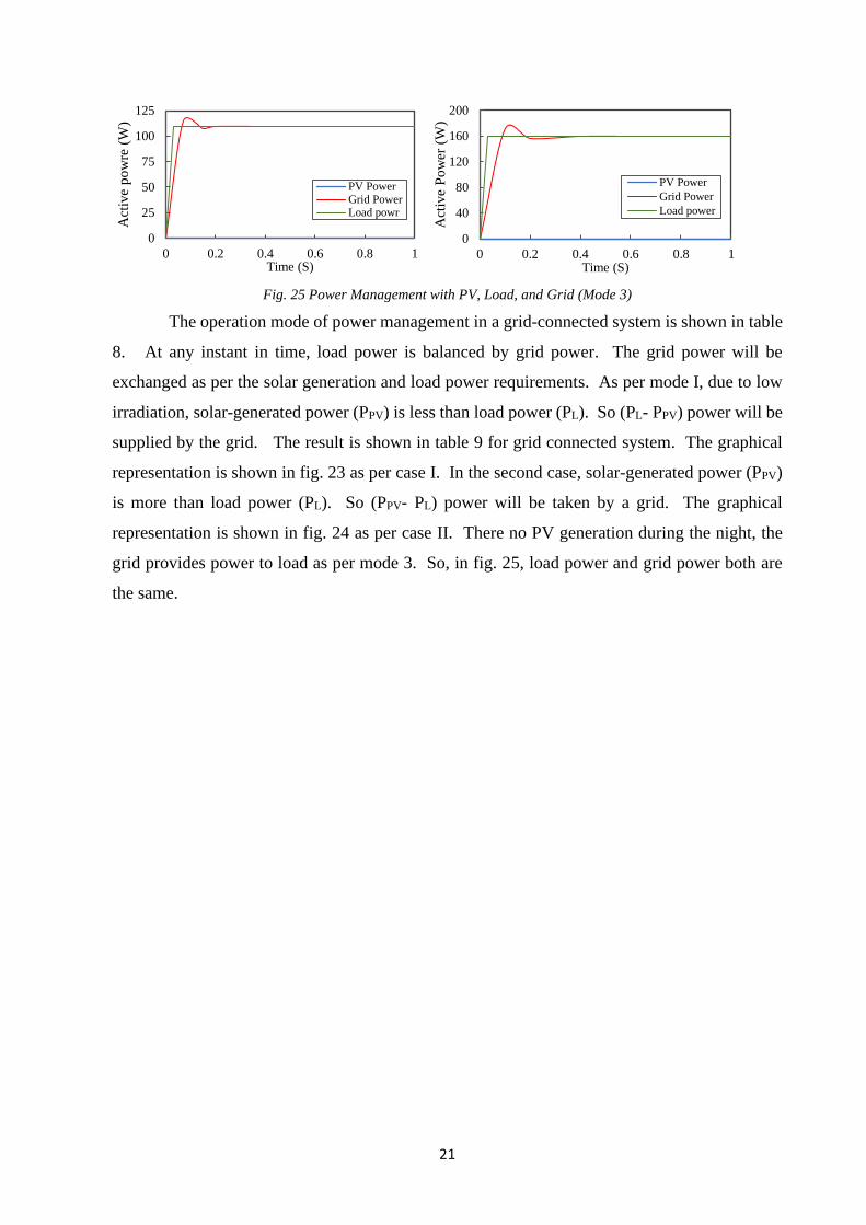
Fig. 25 Power Management with PV, Load, and Grid (Mode 3)
The operation mode of power management in a grid-connected system is shown in table
8. At any instant in time, load power is balanced by grid power. The grid power will be
exchanged as per the solar generation and load power requirements. As per mode I, due to low
irradiation, solar-generated power (PPV) is less than load power (PL). So (PL- PPV) power will be
supplied by the grid. The result is shown in table 9 for grid connected system. The graphical
representation is shown in fig. 23 as per case I. In the second case, solar-generated power (PPV)
is more than load power (PL). So (PPV- PL) power will be taken by a grid. The graphical
representation is shown in fig. 24 as per case II. There no PV generation during the night, the
grid provides power to load as per mode 3. So, in fig. 25, load power and grid power both are
the same.
0
25
50
75
100
125
0 0.2 0.4 0.6 0.8 1
Act
ive
po
wre
(W
)
Time (S)
PV PowerGrid PowerLoad powr
0
40
80
120
160
200
0 0.2 0.4 0.6 0.8 1
Act
ive
Po
wer
(W
)
Time (S)
PV Power
Grid Power
Load power
22
7. Achievements with Respect to Objectives
• Power management strategy for renewable source dominate hybrid microgrid is proposed
in this research work. The key point is power management in the hybrid microgrid to keep
power balance among Distributed Generation (DG), Energy Storage (ES) battery, utility
grid, and load at all times, and maintained bus voltage.
• The power management algorithm is proposed for a hybrid microgrid where bus voltage is
the main carrier for a different mode of operation to maintain power balance among source
and load.
• Voltage shifting based primary droop control method is introduced to avoid the drawback
of poor voltage regulation of conventional primary droop control strategy. This control
strategy can achieve power-sharing as well as bus voltage regulation.
• Transient response during suddenly step up a load in secondary control, there is no current
sharing error of converter current. And at the same time, the voltage response of the
converter is also good. The voltage of each converter is maintained as per the bus voltage.
The same transient response performance is also achieved for current sharing and voltage
restoration in secondary control during suddenly step down load.
• By combining two average currents and droop coefficient controllers, current sharing and
voltage regulation are good under fast-changing load current. As compared to the primary
control scheme, both current sharing accuracy and voltage regulation are achieved better
by using secondary control schemes.
• As per experiment analysis, various parameters are finding out at different irradiance and
temperature in series and parallel connected PV module. The P-V and I-V curve at MPP
is observed at different irradiance by using a real-time plotter. From graphical
representation, it is analyzed that current and power both are increases at higher irradiance
in series connected module compared to a parallel connected module.
• When solar irradiations are enough in standalone systems, electricity generation is usually
more than the house's local load requirement. So extra power is used to charge the battery.
When PV power is less than load power, the battery is providing the power to load. So,
both AC and DC voltage is to be maintained to its rated value.
• However, the grid-tied PV system is beneficial in terms of the excessive power which can
be sold to the grid. When solar irradiation is not sufficient, load power is balanced by PV
and grid. Likewise, for night-time, the only grid supplies power to load.
23
8. Conclusion
The hybrid microgrid is presented with renewable sources (PV & wind), battery, and AC
grid in islanding and grid-connected mode. It is operated in different modes to sustain power
balance by detecting the change in bus voltage. Droop control strategy is applied for proportional
load sharing between parallel converter for power management. For variable load condition, the
hybrid microgrid is operated in a different mode, and load power is balanced by AC grid, DG, or
battery unit. In a conventional primary droop control scheme, voltage degrades while increasing
the load current. So, voltage shifting based droop control strategy is applied at the primary level
to improve voltage regulation.
A further distributed secondary control scheme is also used with compensating
controllers. The average voltage controller is compensating the average value of output voltage
over the primary controller. By combining the average current controller and droop coefficient
compensating controller, adapting the droop resistance can be realized, and the two converter's
output impedance would be the same. So, current sharing accuracy is precisely reached. Also,
by combining these two average current and droop coefficient controller, current sharing and
voltage regulation is good under fast-changing load current in a secondary control scheme. The
simulation results verify the implemented control strategy for the stable operation of the hybrid
microgrid.
Experimental analysis for Power management is also done for variable load in the
islanding and grid-connected PV system. In the islanding PV system, series and parallel
connected two PV modules are tested with real-time monitoring for different temperatures and
radiation. And at different loads, if irradiation is sufficient, then PV power is given to the battery
and load; otherwise, load sinks the power from battery and PV If irradiation is enough in a grid-
connected PV system, extra power is fed to the grid; otherwise, load sinks power from grid and
PV.
24
9. Paper Publication
[1] K A Jadav, H M Karkar, I N Trivedi, “A Review of Microgrid Architectures and Control
Strategy,” Journal of The Institution of Engineers (India): Series B, IEI Springer, (2017):
591-598.
[2] H M Karkar, I N Trivedi, “Primary and Secondary Droop Control Method for Islanded
Microgrid with Voltage Regulation and Current Sharing,” A. Mehta et al. (eds.), Advances
in Control Systems and its Infrastructure, Lecture Note in Electrical Engineering 604,
Springer Nature Singapore Pte Ltd., Proceeding in International Conference on Power,
Control and Communication Infrastructure (ICPCCI), (2019): 75-86.
[3] H M Karkar, I N Trivedi, P K Ghosh, “Power Management in Hybrid Microgrid,”
International Journal of Innovative Technology and Exploring Engineering, Vol 9,
(2020):1964-1969.
[4] H M Karkar, I N Trivedi, Hitarth Buch, “Control Strategy for Power Management in Grid-
Connected Microgrid with Renewable Energy Sources,” International Journal of
Electrical Engineering & Technology, Vol 10, (2019):1-10.
[5] H M Karkar, I N Trivedi, “Experimental Analysis of I-V and P-V Characteristics for Series
and Parallel Combination of PV Modules,” International Journal of Advance Research in
Science and Engineering, Vol 7, (2018): 42-53.
[6] H M Karkar, I N Trivedi, R P Sukhadiya, “Impact of Transmission Line Inductance and
Capacitance on Voltage Quality at PCC in Microgrid,” Journal of Emerging Technologies
and Innovative Research, Vol 4, (2018): 125-132.
[7] H M Karkar, I N Trivedi, P K Ghosh, “Experimental Performance of Voltage Quality at
PCC and Power Management in Grid-Connected System” communicated to International
Journal of Ambient Energy, Taylor & Francis.
[8] H M Karkar, I N Trivedi, P K Ghosh, “Real-Time Parameter Comparison and Power
Management in Standalone Photovoltaic Generation System” submitted to SN Applied
Sciences, Springer.
25
10. References
[1] Carreras BA, et al. "Evidence for self-organized criticality in a time series of electric power system
blackouts", IEEE Trans Circuit Syst: Regul Pap 2004; 51:1733–40.
[2] Nichols DK, et al. "Validation of the CERTS microgrid concept the CEC/CERTS microgrid testbed", In:
Proceedings of the 2006 IEEE Power Engineering Society General Meeting. 2006.
[3] Barklund E, et al. "Energy management in autonomous microgrid using stability constrained droop control
of inverters", IEEE Trans Power Electron 2008; 23:2346–52.
[4] Su S, et al. "Self-organized criticality of power system faults and its application in adaptation to extreme
climate", Chin Sci Bull 2009; 54:1251–9.
[5] Satish B, Bhuvaneswari S. "Control of microgrid: a review", In: Proceedings of the 2014 International
Conference on Advances in Green Energy (ICAGE), 2014. pp. 18–25.
[6] Kyoungsoo R, Rahman S. "Two-loop controller for maximizing performance of a grid-connected
photovoltaic-fuel cell hybrid power plant", IEEE Trans Energy Convers 1998; 13:276–81.
[7] Lasseter R, Piagi P. "Providing premium power through distributed resources", In: Proceedings of the 33rd
annual Hawaii international conference on system sciences. 2000. pp. 1–9.
[8] Katiraei F, Iravani MR., "Power management strategies for a microgrid with multiple distributed generation
units", IEEE Trans Power Syst 2006; 21:1821–31.
[9] Piagi P, Lasseter RH. "Autonomous control of microgrids", In: Proceedings of the 2006 IEEE Power
Engineering Society General Meeting. 2006.
[10] Zeng Z, et al. "Study on small signal stability of microgrids: a review and a new approach", Renew Sustain
Energy Rev 2011; 15:4818–28.
[11] J.M. Guerrero, J.C. Vasquez, J. Matas, L.G. de Vicuna, M. Castilla, "Hierarchical control of droop-controlled
AC and DC microgrids—a general approach toward standardization", IEEE Trans. Ind. Electron. 58 (1)
(2011) 158–172.
[12] S. Anand, B.G. Fernandes, M. Guerrero, "Distributed control to ensure proportional load sharing and improve
voltage regulation in low voltage DC microgrids", IEEE Trans. Power Electron. 28 (4) (2013) 1900–1913.
[13] J.M. Guerrero, Lijun Hang, J. Uceda, "Control of distributed uninterruptible power supply systems", IEEE
Trans. Ind. Electron. 55 (8) (2008) 2845–2859
[14] Guerrero, J.M.; Vasquez, J.C.; Matas, J. "Hierarchical control of droop-controlled AC and DC Microgrids—
A general approach toward standardization", IEEE Trans. Ind. Electron. 2011, 58, 158–172.
[15] Chen, D.; Xu, L. "Autonomous DC voltage control of a DC microgrid with multiple slack terminals", IEEE
Trans. Power Syst. 2012, 27, 1897–190.
[16] Han, Y.; Chen, W.R.; Li, Q. "Energy management strategy based on multiple operating states for a
photovoltaic/fuel cell/energy storage DC microgrid", Energies 2017, 10, 136.
[17] H. Kakigano, Y. Miura, and T. Ise, "Low-voltage bipolar-type dc microgrid for super high-quality
distribution," IEEE Trans. Power Electron., vol. 25, no.12, pp. 3066–3075, Dec. 2010
[18] L. Meng, T. Dragicevic, J. M. Guerrero, and J. C. Vasquez, "Dynamic consensus algorithm based distributed
global efficiency optimization of a droop-controlled DC microgrid," in Proc. IEEE Int. Eng. Conf., 2014, pp.
1276–1283.
[19] A. Khorsandi, M. Ashourloo, and H. Mokhtari, "A decentralized control method for a low-voltage DC
microgrid," to appear in IEEE Trans. Energy Convers., pp. 793–801.
[20] T. Dragičević, X. Lu, J. C. Vasquez, and J. M. Guerrero, "DC Microgrids–Part I: A Review of Control
Strategies and Stabilization Techniques," to appear in IEEE Trans. Power Electron., doi:
10.1109/TPEL.2015.2478859.
[21] D. Chen, L. Xu, and L. Yao, "DC voltage variation based autonomous control of dc microgrids," IEEE Trans.
Power Del., vol. 28, no. 2, pp. 637–648, 2013.
[22] L. Che, and M. Shahidehpour, "DC microgrids: economic operation and enhancement of resilience by
hierarchical control," IEEE Trans. Smart Grid, vol. 5, no. 5, pp. 2517–2526, Sept. 2014.
26
[23] Q. Shafiee, T. Dragicevic, J.C. Vasquez, and J. M. Guerrero "Hierarchical control for multiple DC-microgrids
clusters," IEEE Trans. Energy Convers., vol. 29, no. 4, pp. 922–933, Dec. 2014.
[24] C. Lin, P. Wang, J. Xiao, Y. Tang, and F. H. Choo, "Implementation of hierarchical control in dc microgrids,"
IEEE Trans. Ind. Electron., vol. 61, no. 8, pp. 4032–4042, Aug. 2014.
[25] T. Dragicevic, J. Guerrero, J. Vasquez, and D. Skrlec, "Supervisory control of an adaptive-droop regulated
dc microgrid with battery management capability," IEEE Trans. Power Electron., vol. 29, no. 2, pp. 695–
706, Feb. 2014.
[26] P. Huang, W. Xiao, and M. S. Moursi, "A practical load sharing control strategy for DC microgrids and DC
supplied houses," in Proc. 39th Annu. Conf. IEEE Ind. Electron. Soc., 2013, pp. 7122–7126.
[27] A. P. N. Tahim, D. J. Pagano, E. Lenz, and V. Stramosk, "Modeling and stability analysis of islanded DC
microgrids under droop control," to appear in IEEE Trans. Power Electron., doi:
10.1109/TPEL.2014.2360171.
[28] Y. Gu, X. Xiang, W. Li, and X. He, "Mode-adaptive decentralized control for renewable DC microgrid with
enhanced reliability and flexibility," IEEE Trans. Power Electron., vol. 29, no. 9, pp. 5072–5080, Sep. 2014.
[29] J. Beerten, and R. Belmans, "Analysis of power sharing and voltage deviations in droop-controlled DC grids,"
IEEE Trans. Power Syst., vol. 28, no. 4, pp. 4588–4597, Nov. 2013.
[30] Gulin Marko, "Control of a DC Microgrid", 2012, http://www.fer.ur/download/KDI Marko Gulin.pdf.
[31] T. Dragicevic, J.M. Guerrero, J.C. Vasquez, D. Skrlec, "Supervisory control of an adaptive-droop regulated
DC microgrid with battery management capability", IEEE Trans. Power Electron, 29 (2) (2014) 695–706.
[32] Y. Ito, Y. Zhongqing, H. Akagi, "DC micro-grid-based distribution power generation system", in: Power
Electronics and Motion Control Conference, vol. 3, 2004, pp. 1740–1745.
[33] Zhihong Ye, D. Boroyevich, Kun Xing, F.C. Lee, "Design of parallel sources in DC distributed power systems
by using gain-scheduling technique", in: Power Electronics Specialists Conference. vol. 1, 1999, pp. 161–
165.
[34] S. Anand, B.G. Fernandes, M. Guerrero, "Distributed control to ensure proportional load sharing and improve
voltage regulation in low voltage DC microgrids", IEEE Trans. Power Electron, 28 (4) (2013) 1900–1913.
[35] H. Kakigano, A. Nishino, T. Ise, "Distribution voltage control for DC microgrid with fuzzy control and gain-
scheduling control", in: IEEE Eighth International Conference on Power Electronics and ECCE Asia (ICPE
& ECCE), 2011, pp.256–263.
[36] D. Salomonsson, L. Soder, A. Sannino, "An adaptive control system for a DC microgrid for data centres",
IEEE Trans. Ind. Appl. 44 (6) (2008) 1910–1917.
[37] Z.H. Jian, Z.Y. He, J. Jia, Y. Xie, "A review of control strategies for DC micro-grid", in: Fourth International
Conference on Intelligent Control and Information Processing (ICICIP), 2013, pp. 666–671.
[38] H. Kakigano, Y. Miura, T. Ise, R. Uchida, "DC microgrid for super high-quality distribution-system
configuration and control of distributed generations and energy storage devices", in: Power Electronics
Specialists Conference PESC'06, 2006, pp. 1–7.
[39] Baochao Wang, M. Sechilariu, F. Locment, "Intelligent DC microgrid with smart grid communications:
control strategy consideration and design", IEEE Trans. Smart Grid 3 (4) (2012) 2148–2156.
[40] T. Dragicevic, J.M. Guerrero, J.C. Vasquez, D. Skrlec, "Supervisory control of an adaptive-droop regulated
DC microgrid with battery management capability", IEEE Trans. Power Electron. 29 (2) (2014) 695–706.
[41] Xiaonan Lu, J.M. Guerrero, Kai Sun, J.C. Vasquez, "An improved droop control method for DC microgrids
based on low bandwidth communication with DC bus voltage restoration and enhanced current sharing
accuracy", IEEE Trans. Power Electron. 29 (4) (2014) 1800–1812.
[42] W. Qiu, Z. Liang, "Practical design considerations of current sharing control for parallel VRM applications",
in: 20th Applied Power Electronics Conference and Exposition. vol. 1, 2005, pp. 281–286.
[43] T. Dragicevic, J.M. Guerrero, J.C. Vasquez, "A distributed control strategy for coordination of an autonomous
LVDC microgrid based on power line signalling", IEEE Trans. Ind. Electron. 61 (7) (2014) 3313–3326.
[44] FP Maturana, R.J. Staron, D.L. Carnahan, K.A. Loparo, "Distributed control concepts for future power grids",
in: Energytech IEEE, 2013, pp. 1–6.
27
[45] D.H. Moore, J.M. Murray, F.P. Maturana, T. Wendel, K.A. Loparo, "Agent-based control of a DC microgrid",
in: Energytech IEEE, 2013, pp. 1–6.
[46] J. Bryan, R. Duke, S. Round, "Decentralized generator scheduling in a nano grid using DC bus signalling",
in: IEEE Power Engineering Society General Meeting. vol. 1, 2004, pp. 977–982.
[47] Zhang Li, Tianjin Wu, Xing Yan, Kai Sun, JM Gurrero, "Power control of DC micro-grid using DC bus
signalling", in: 26th Applied Power Electronics Conference and Exposition (APEC) IEEE, 2011, pp. 1926–
1932.
[48] J.K. Schonberger, "Distributed Control of a Nano grid Using DC Bus Signalling", University of Canterbury,
Christchurch, New Zealand, 2005.
[49] Xiaofeng Sun, Zhizhen Lian, Baocheng Wang, Xin Li, "A hybrid renewable DC microgrid voltage control",
in: IEEE Sixth International Power Electronics and motion Control Conference, IPEMC, 2009, pp. 725–729.
[50] A. Tuladhar, K. Jin, "A novel control technique to operate DC/DC converters in parallel with no control
interconnections", in: 29th Annual IEEE Power Electronic Specialists Conference. vol. 1, 1998, pp. 892–898.
[51] J. M. Guerrero, J. Vasquez, J. Matas, L. de Vicuna, and M. Castilla, "Hierarchical control of droop-controlled
ac and DC microgrids a general approach toward standardization," IEEE Trans. Ind. Electron., vol. 58, no.
1, pp. 158 –172, Jan. 2011.
[52] S. Anand, B. G. Fernandes, and J. M. Guerrero, "Distributed control to ensure proportional load sharing and
improve voltage regulation in low voltage DC microgrids", IEEE Trans. Power Electron., vol. 28, no. 4, pp.
1900–1913, Apr. 2013.
[53] X. Lu, J. M. Guerrero, K. Sun, and J. Vasquez, "An improved droop control method for dc microgrids based
on low bandwidth communication with dc bus voltage restoration and enhanced current sharing accuracy",
IEEE Trans. Power Electron., vol. 29, no. 4, pp. 1800–1812, Apr. 2014.
[54] V. Nasirian, S. Moayedi, A. Davoudi, and F. L. Lewis, "Distributed cooperative control of DC microgrids",
IEEE Trans. Power Electron., vol. 30, no. 4, pp. 2288–2303, Apr. 2015.
[55] V. Nasirian, A. Davoudi, F. L. Lewis, and J. M. Guerrero, "Distributed adaptive droop control for DC
distribution systems", IEEE Trans. Energy Convers., vol. 29, no. 4, pp. 944–956, Dec. 2014.
[56] Q. Shafiee, J. M. Guerrero, and J. C. Vasquez, "Distributed secondary control for islanded microgrids – a
novel approach", IEEE Trans. Power Electron., vol. 29, no. 2, pp. 1018–1031, Feb. 2014.
[57] X. Yu, X. She, and A. Huang, "Hierarchical power management for DC microgrid in islanding mode and
solid-state transformer enabled mode", in Proc. 39th Annu. Conf. IEEE Ind. Electron. Soc., 2013, pp.1656–
1661.
[58] H. Han, Y. Liu, Y. Sun, M. Su, and J. M. Guerrero, "An improved droop control strategy for reactive power
sharing in islanded microgrid", to appear in IEEE Trans. Power Electron., doi: 10.1109/TPEL.2014.2332181.
[59] P.C. Loh, D. Li, YK. Chai, F. Blaabjerg, "Autonomous control of interlinking converter with energy storage
in hybrid AC–DC microgrid", IEEE Trans. Ind. Appl. 49(3), 1374–1382 (2013).
[60] A. Mohamed, M. Elshaer, O. Mohammed, "Bi- directional AC– DC/DC–AC converter for power sharing of
hybrid AC/DC systems", in Power and Energy Society General Meeting (IEEE, 2011), pp. 1–8.
[61] J. Zhang, D. Guo, F. Wang, Y. Zuo, H. Zhang, "Control strategy of interlinking converter in hybrid AC/DC
Microgrid", in International Conference on Renewable Energy Research and Applications (ICRERA) (IEEE,
2013), pp. 97–102.
[62] S.-H. Park, J.-Y. Choi, D.-J. Won, "Cooperative control between the distributed energy resources in AC/DC
hybrid microgrid", in Innovative Smart Grid Technologies Conference (ISGT) (IEEE PES, 2014), pp. 1–5.
[63] MN Ambia, A. Al-Durra, S.M. Muyeen, "Centralized power control strategy for AC–DC hybrid micro-grid
system using multi converter scheme", in IECON 2011, 37th Annual Conference on IEEE Industrial
Electronics Society (2011, pp. 843–848).
[64] M. Goyal, A. Ghosh, F. Zare, "Power sharing control with frequency droop in a hybrid microgrid", in Power
and Energy Society General Meeting (PES) (IEEE, 2013), pp. 1–5.
[65] R. Majumder, A. Ghosh, G. Ledwich, F. Zare, "Operation and control of hybrid microgrid with angle droop
controller", in TENCON 2010 IEEE Region 10th Conference 2010, pp. 509–515.

28
[66] R. Majumder, B. Chaudhuri, A. Ghosh, G. Ledwich, F. Zare, "Improvement of stability and load sharing in
an autonomous microgrid using supplementary droop control loop", Power Syst. IEEE Trans. 25(2), 796–
808 (2010).
[67] R. Majumder, A. Ghosh, G. Ledwich, F. Zare, "Power system stability and load sharing in distributed
generation", in Power System Technology and IEEE Power India Conference, POWERCON 2008, pp. 1–6.
[68] K. Rouzbehi, A. Miranian, J.I. Candela, A. Luna, P. Rodriguez, "Intelligent voltage control in a DC microgrid
containing PV generation and energy storage", in IEEE PES, T&D Conference and Exposition (2014), pp. 1–
5.