Embed Size (px)
Citation preview
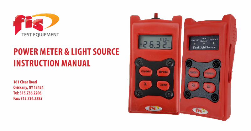
Power Meter & Light SourceinStruction ManuaL
161 clear roadoriskany, nY 13424tel: 315.736.2206Fax: 315.736.2285
TEST EQUIPMENT

introduction
@FISsales | /FISsales | fiberinstrumentsales.com | 1.800.5000.FIS (347) 1
This manual covers FIS Power Meters with 0.01 dBm resolution. The manual also covers single, dual, and hybrid FIS Light Sources in both multimode and singlemode wavelengths. These units feature efficient circuitry for prolonged battery life, easy-to-operate button controls, and a high-impact case. FIS Hand Held Power Meters and Light Sources are suitable for field installation and service work as well as laboratory use.
The FIS product line offers a choice of three different light source variants - single wavelength (850nm or 1300nm LED, 1310nm, 1490nm or 1550nm LASER), dual wavelength (850nm and 1300nm LED, 1310nm and 1550nm, 1310nm and 1490nm, 1490nm and 1550nm LASER),
and hybrid wavelength (1300nm LED and 1310nm LASER). Other dual hybrids are available per request.
The FIS Power Meter is rugged, compact, and easy to use. Featuring a dynamic range of 70 dB for both standard and CATV variants, our power meters operate at the three most common wavelengths in the fiber optics industry today: 850, 1310 and 1550nm. FIS also offers power meters in standard and CATV versions incorporating the 1310, 1490, and 1550nm wavelengths.The FIS Power Meter features a zero set function and auto shut-off. Included with the unit are a handy rubber holster and universal power meter adapters (2.5 & 1.25mm).
introduction
1.800.5000.FIS (347) | fiberinstrumentsales.com | @FISsales | /FISsales2
The FIS Hand Held Light Source provides performance, durability, and flexibility. New features include: • LED annunciators indicate currently selected source.• “LOW BAT” Indicator which informs the operator when to replace battery – reducing a possible source of erroneous readings.• Newly designed circuitry to extend battery life.• Customer choice of connector style: multimode standard ST, singlemode standard FC and SC.• Rugged solid rubber boot – ideal for industrial settings or use in field.• Modulation circuitry provides audio-frequency 2-kHz square wave for use with fiber identifiers.
• Power save circuitry to eliminate unnecessary battery drain. Unit goes into sleep mode if no button strikes are detected for 3.5 hours. Unit may reactivated by simply hitting on/off key.• Automatic sleep mode feature may be disabled by holding down “ON/OFF” button for five seconds or until LED annunciator flickers.• Non-volatile memory feature retains source and modulation setting from previous use once reactivated from sleep mode, or after having been shut off.• 9V alkaline battery included.
Light Source Features warning

1.800.5000.FIS (347) | fiberinstrumentsales.com | @FISsales | /FISsales @FISsales | /FISsales | fiberinstrumentsales.com | 1.800.5000.FIS (347) 3
Do not install any angled-physical contact (aPc) connectors into the 850nm Light Source output port. angled connectors are for 1310nm, 1490nm, and 1550nm (single mode) use only. the 850nm LeD is for multimode use. Due to multimode connector tolerances, the sharp point of an angled ferrule may crack the lens of many 850nm LeD sources and cause erroneous readings.
although the u.S DhSS (Department of health and human Services) does not classify class 1 emission levels (output power level below 1mw) as hazardous, please note that LaSer light sources operate at significantly higher power levels than do LeD light sources.
the LaSer radiation emitted from these sources (even though invisible) may damage eyesight with prolonged exposure. avoid looking directly into an optical port or any patchcord connector attached to a LaSer source.
warning

1.800.5000.FIS (347) | fiberinstrumentsales.com | @FISsales | /FISsales4
LASER Sources• Optical Wavelengths: single LASER source – 1310nm or 1550nm or 1490nm dual LASER source – 1310nm/1550nm hybrid LED/LASER – 1300nm/1310nm• Rated Optical Power** -1.00dBm (minimum)• Spectral Bandwidth: 15nm @ 1310nm – typical 15nm @ 1490nm – typical 15nm @ 1550nm – typical• Optical Temperature Range: -40ºC to +85º C* with 62.5µm launch cord**with 9µm launch cord
FIS Hand Held LASER Unit Sources have been designed to comply with United States Title 21, CFR (Code of Federal Regulations), Parts 1040.10 and 1040.11 for Class 1 emission limits.
LED sources• Optical Wavelengths: single LED source – 850nm or 1300nm dual LED source – 850/1300nm• Rated Optical Power*: -19 dBm @850nm – min -19 dBm @1300nm –min• Spectral Bandwidth: LED sources: 35nm @ 850nm – typical 140nm @ 1300nm – typical• Operating Temperature Range:+ 14º to +122º F (-10º to +50º C)
Light Source Specifications Power Meter Features

1.800.5000.FIS (347) | fiberinstrumentsales.com | @FISsales | /FISsales @FISsales | /FISsales | fiberinstrumentsales.com | 1.800.5000.FIS (347) 5
The FIS Hand Held Power Meter provides performance, durability, and flexibility. New features include:• Easy to read LCD display.• Independent Zero Set function for each wavelength; user may conveniently store a unique zero reference level for each of the three available wavelengths.• “LOW BAT” indicator that informs the operator when to replace battery – reducing a possible source of erroneous readings.• Power save circuitry to eliminate unnecessary battery drain. Unit goes into sleep mode if no button strikes are detected for 25 minutes. Unit may be reactivated by simply pressing the ON/OFF button.
• Memory circuitry that retains wavelength and ZERO SET setting from previous use once reactivated from sleep mode or after having been shut off.• Automatic sleep mode feature may be disabled by holding down “ON/OFF” button for five seconds or until LCD annunciator flickers.• Customer can order these adapter styles: ST, SC, FC, or SMA. Two universal adapters are included with each unit (2.5mm & 1.25mm).• Rugged solid-rubber boot – ideal for industrial settings or use in the field.• Easy to use pushbutton switches. • 9V alkaline battery included
Power Meter Features
1.800.5000.FIS (347) | fiberinstrumentsales.com | @FISsales | /FISsales6
• Detector: 2mm Germanium Photodiode
• Dynamic range: 70 dB (+5 dBm to –65 dBm – Standard model) (+23 dBm to –45 dBm – CATV Singlemode) (+23dBm to –30dBm – CATV Multimode)
• Wavelength settings: 850nm/1310nm/1550nm 1310nm/1490nm/1550nm
• Operating temperature: +14º F to +122º F -10º C to +50º C
• Accuracy: ± 0.3 dB (+5 dBm to –60 dBm) ± 0.6 dB (-60 dBm to –65 dBm)
• Adapters (Power Meter)
• 1 Reference Patchcord (included in Test Set Kit only)
• 1 Mating Sleeve (included in Test Set Kit only)
Power Meter Specifications accessories general inspection

1.800.5000.FIS (347) | fiberinstrumentsales.com | @FISsales | /FISsales @FISsales | /FISsales | fiberinstrumentsales.com | 1.800.5000.FIS (347) 7
Prior to shipment, this instrument was inspected and found to be free of mechanical and electrical defects. The carrier assumes responsibility from pickup to delivery. Should damage occur to the instrument in shipping, notify the carrier and FIS immediately. Verify that your unit is in working order by completing the following steps.
Light Source
1. Turn on the light source on and allow to warm up for five minutes.
2. Remove the plastic cap from the light source output port and connect the appropriate patchcord (multimode for 850 and 1300nm, singlemode for 1310, 1490, and 1550nm).
Note: By convention, jacketed fiber is color-coded: yellow for singlemode, orange, gray or another color for multimode.
3. Connect free end of patchcord to power meter and set for the appropriate wavelength.
4. Verify that light source output power levels read approximately:
LED Sources -19 dBm @ 850nm (multimode) -19 dBm @ 1300nm (multimode) LASER Sources -1.00 dBm @ 1310nm (singlemode) -1.00 dBm @ 1550nm (singlemode) -1.00 dBm @ 1490nm (singlemode)
general inspection
1.800.5000.FIS (347) | fiberinstrumentsales.com | @FISsales | /FISsales8
Power Meter
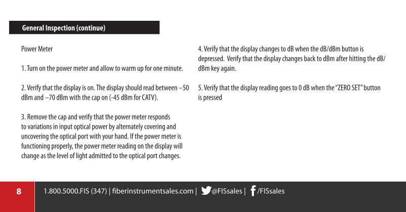
1. Turn on the power meter and allow to warm up for one minute.
2. Verify that the display is on. The display should read between –50 dBm and –70 dBm with the cap on (-45 dBm for CATV).
3. Remove the cap and verify that the power meter responds to variations in input optical power by alternately covering and uncovering the optical port with your hand. If the power meter is functioning properly, the power meter reading on the display will change as the level of light admitted to the optical port changes.
4. Verify that the display changes to dB when the dB/dBm button is depressed. Verify that the display changes back to dBm after hitting the dB/dBm key again.
5. Verify that the display reading goes to 0 dB when the “ZERO SET” button is pressed
general inspection (continue)

1.800.5000.FIS (347) | fiberinstrumentsales.com | @FISsales | /FISsales @FISsales | /FISsales | fiberinstrumentsales.com | 1.800.5000.FIS (347) 9
a word about Decibel (dB) and (dBm) settings
The decibel (dB) is widely used in the electronics and fiber optics industries. Used to express gain or loss, the decibel is a logarithmic ratio between the power entering the system or individual component and the power leaving it. The usefulness of such a measurement (particularly for fiber optic systems) lies in the fact that the effects (gain or loss) of individual components, such as amplifiers, attenuators, or lengths of fiber optic cable, may be easily determined prior to actual insertion in a fiber optic link. This makes calculating total system loss a matter of simply adding the individual loss or gain of each component.
Additionally, once total system loss (in dB) is determined, it can be used to accurately predict the output strength of any input signal, regardless of magnitude.The dBm, read as the “decibel referenced to a milliwatt,” is a measurement of emitted optical power. The dBm, although derived from the decibel (dB), may be converted to milliwatts (mW) using the relationships on the following page. Note: Power measurements lower in magnitude than 1mW are rendered as negative values in dBm (e.g: 0.50 mW = -3.0 dBm). Additionally, a power reading of 0.00 dBm is actually a high power reading equal to 1mW. LASER sources typically operate in this range. See charts on following pages for quick references.
1.800.5000.FIS (347) | fiberinstrumentsales.com | @FISsales | /FISsales10
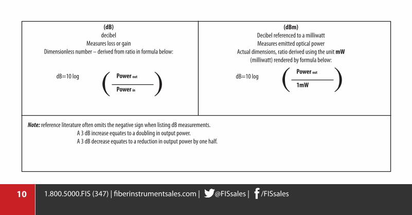
(dB)decibel
Measures loss or gainDimensionless number – derived from ratio in formula below:
dB=10 log ( )Power out
Power in
(dBm)Decibel referenced to a milliwattMeasures emitted optical power
Actual dimensions, ratio derived using the unit mw(milliwatt) rendered by formula below:
dB=10 log ( )Power out
1mw
Note: reference literature often omits the negative sign when listing dB measurements. A 3 dB increase equates to a doubling in output power. A 3 dB decrease equates to a reduction in output power by one half.

1.800.5000.FIS (347) | fiberinstrumentsales.com | @FISsales | /FISsales @FISsales | /FISsales | fiberinstrumentsales.com | 1.800.5000.FIS (347) 11
Loss in dB and Percent (%) Power remaining
Loss (dB) % of Power remaining Loss (dB) % of Power
remaining
0.1 97.7 1.0 79.4
0.2 95.5 3.0 50.10.3 93.3 5.0 31.60.4 91.2 10.0 10.00.5 89.1 20.0 1.00.6 87.1 30.0 0.10.7 85.1 40.0 0.010.8 83.2 50.0 0.0010.9 81.1 60.0 0.0001
Power (µw) to dBm conversion chart
Power (µw) (dBm) Power (µw) (dBm)
2000 3.0 10 -20.0
1000 0.0 5 -23.0900 -0.5 1 -30.0800 -1.0 .900 -30.5500 -3.0 .700 -31.5400 -4.0 .500 -33.0200 -7.0 .400 -34.0100 -10.0 .300 -35.230 -15.2 .200 -37.020 -17.0 .100 -40.0
1.800.5000.FIS (347) | fiberinstrumentsales.com | @FISsales | /FISsales12
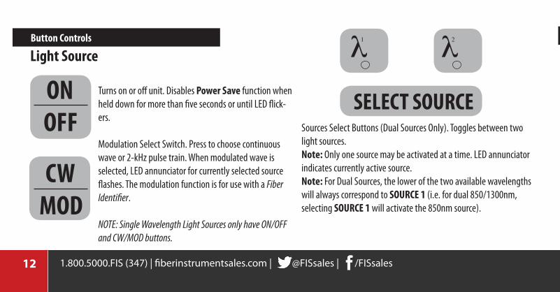
Turns on or off unit. Disables Power Save function when held down for more than five seconds or until LED flick-ers.
Modulation Select Switch. Press to choose continuous wave or 2-kHz pulse train. When modulated wave is selected, LED annunciator for currently selected source flashes. The modulation function is for use with a Fiber Identifier.
NOTE: Single Wavelength Light Sources only have ON/OFF and CW/MOD buttons.
Sources Select Buttons (Dual Sources Only). Toggles between two light sources.note: Only one source may be activated at a time. LED annunciator indicates currently active source.note: For Dual Sources, the lower of the two available wavelengths will always correspond to Source 1 (i.e. for dual 850/1300nm, selecting Source 1 will activate the 850nm source).
SeLect SourceonoFF
l1 l2Button controls
cwMoD
Button controls (continue)
Light Source
1.800.5000.FIS (347) | fiberinstrumentsales.com | @FISsales | /FISsales @FISsales | /FISsales | fiberinstrumentsales.com | 1.800.5000.FIS (347) 13
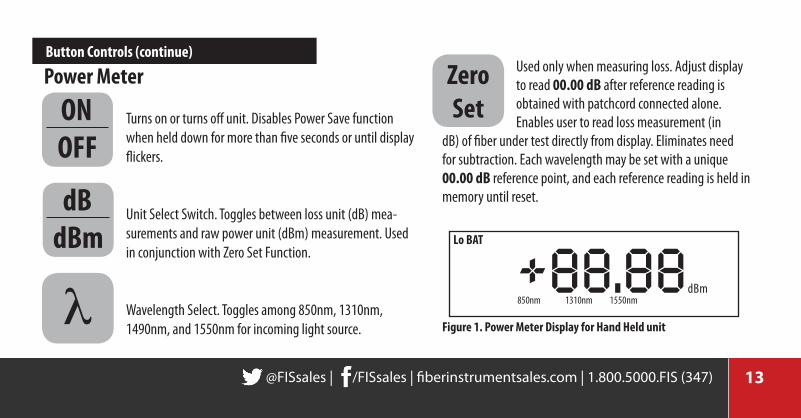
Turns on or turns off unit. Disables Power Save function when held down for more than five seconds or until display flickers.
Unit Select Switch. Toggles between loss unit (dB) mea-surements and raw power unit (dBm) measurement. Used in conjunction with Zero Set Function.
Wavelength Select. Toggles among 850nm, 1310nm, 1490nm, and 1550nm for incoming light source.
Power Meter Used only when measuring loss. Adjust display to read 00.00 dB after reference reading is obtained with patchcord connected alone. Enables user to read loss measurement (in
dB) of fiber under test directly from display. Eliminates need for subtraction. Each wavelength may be set with a unique 00.00 dB reference point, and each reference reading is held in memory until reset.
Zero Set
+88.88 dBm
Lo Bat
850nm 1310nm 1550nm
Figure 1. Power Meter Display for hand held unitl
Button controls (continue)
onoFF
dBdBm
1.800.5000.FIS (347) | fiberinstrumentsales.com | @FISsales | /FISsales14
To take loss measurements in a patchcord (connectorized on both ends), you will need:
1 Light Source 1 Power Meter 1 Reference Patchcord (cord #1) 1 Test Patchcord (cord #2) 1 Mating Sleeve note: Before beginning test, allow the units a 5 minutes. warm up time and ensure that all connector ferrules are clean. Fiber optic connectors account for the most significant source of loss (or attenuation) in fiber optic links. The loss incurred by a system due to length of the fiber used is usually negligible for short distances.
To accurately measure connector losses, the “connectorized” end of the fiber under test must be isolated from the light source. This is necessary to more closely simulate the loss characteristics of the connector when joined to another connector – as it would actually appear on a fiber optic link. For this reason the use of a reference cord is necessary.
Step 1. You must first determine the power level of the light exiting the reference patchcord.
Step 2. Determining the loss of a patchcord may be done in two different ways. One way is to record the power (reference) level and perform subtractions. The second (and simpler) method is to use the “Zero Set” feature present on all FIS OV Series Power Meters. Both methods are described here.
taking Power and Loss Measurements
1.800.5000.FIS (347) | fiberinstrumentsales.com | @FISsales | /FISsales @FISsales | /FISsales | fiberinstrumentsales.com | 1.800.5000.FIS (347) 15
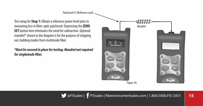
Test setup for Step 1: Obtain a reference power level prior to measuring loss in fiber-optic patchcord. Depressing the Zero Set button here eliminates the need for subtraction. Optional mandrel* shown in the diagram is for the purpose of stripping out cladding modes from multimode fiber.
*Must be secured in place for testing. Mandrel not required for singlemode fiber.
Patchcord #1 (Reference cord)
Mandrel
Figure 2A.
1.800.5000.FIS (347) | fiberinstrumentsales.com | @FISsales | /FISsales16
taking Power and Loss Measurements (con’t)
You are now ready to read the reference power level (see Figure 2A). It is at this point that the two methods differ. If using the subtraction method, record the dBm reading (a form is provided in the back of this manual for your convenience) [Example: -17.1 dBm]. If using the zero set method, proceed to the next step. Step 2. At this point, depress the “Zero Set” button. Notice that this will have two different effects on the display. The display will simultaneously be set to read 00.0 and the units will change from dBm (power measurement units) to dB (loss measurement units).
The set-up and first step for both the zero set method and for the subtraction method are identical. You must first connect one end of the reference patchcord to the light source and the other end to the power meter. Wrap this patchcord three to four times around the mandrel (or loosely around a highlighter pen) to disperse any light that may be entering the patchcord through the cladding (cladding modes). It is very important to make sure all connections are physically secure and cannot move while taking measurements. Movement of the patchcords or test equipment involved will introduce fluctuating or stray readings. Securing the patchcords to a flat surface with masking tape is recommended. Once connections are physically secure, ensure that both light source and power meter are set for the same wavelength.

1.800.5000.FIS (347) | fiberinstrumentsales.com | @FISsales | /FISsales @FISsales | /FISsales | fiberinstrumentsales.com | 1.800.5000.FIS (347) 17
Disconnect the connector from the power meter and insert this test setup for Steps 2-4.
After obtaining a reference using patchcord #1, this setup allows you to measure the loss of patchcord #2. The use of the Zero Set button in the previous step enables you to read the loss measurement directly from the meter display in units of dB.
Patchcord #1
Mating Sleeve
Figure 2B.

1.800.5000.FIS (347) | fiberinstrumentsales.com | @FISsales | /FISsales18
taking Power and Loss Measurements (con’t)
Remove reference Patchcord #1 from the power meter and connect it to the mating sleeve. Insert one end of patchcord #2 (the cord to be tested) into the open side of the mating sleeve and the other end of this patchcord into the power meter (Figure 2B). At this point, you may directly read from the meter the loss (in dB) that would be incurred from inserting patchcord #2 into a fiber optic system. Step 3. If using the subtraction method, you will not have depressed the “Zero Set” button. After having connected patchcord #2, read the second power level reading from the meter display [Example: -17.5 dBm]. Subtract the first reading from the second [Example: -17.5 – (-17.1 dBm) = -0.4 dB]. The difference between the two readings is the typical loss
(in decibels, not dBm) that will be incurred by insertion of patchcord #2 into a fiber-optic system. This loss figure represents the loss of one connector and one mating sleeve as well as the loss incurred from the length of fiber itself. Step 4. It is recommended to take a second reading by switching the connector l ocations of the patchcord under test (patchcord #2) at the mating sleeve and power meter. Again, subtract the results from the reference reading and record this result. By averaging these two figures any potential error caused by differences between the two connectorized ends of the fiber under test (FUT) will be minimized

1.800.5000.FIS (347) | fiberinstrumentsales.com | @FISsales | /FISsales @FISsales | /FISsales | fiberinstrumentsales.com | 1.800.5000.FIS (347) 19
note: Up to three unique zero references (one for each wavelength) may be stored in the power meter’s memory. Zero references will stay in memory until reset by pressing the “Zero Set” key. Zero references are not lost from memory when unit enters sleep mode or when unit is turned off.
The light source continuous wave/modulation function enables the user to distinguish individual fiber conductors from one another by sending a pulse of varying intensity through the fiber already installed in a network. Depressing the “cw/MoD” key generates a 2-kilohertz square-wave pulse that may be detected through the use of a Fiber Identifier (sold separately). A Fiber Identifier clamps to the outside of a fiber under test and detects the presence of light through the jacket.
note: The handheld power meter is designed to measure primarily continuous wave (cw) light sources. A modulated light source may produce erratic power meter readings under most circumstances.
continuous wave/Modulation Function

1.800.5000.FIS (347) | fiberinstrumentsales.com | @FISsales | /FISsales20
The operating temperature for FIS hand held test equipment is between +14ºF to +122ºF (-10ºC to + 50ºC). Although there is little difference in the detection characteristics of the power meter with variations in temperature [(particularly above freezing (32ºF, 0ºC)], light source output power will vary slightly with changes with temperature. This variability is most prominent at temperatures below freezing. For optimum results therefore, all readings (reference, raw power, and loss) should be obtained at a constant surrounding (or ambient) temperature after the five minute warm-up time.
Accurately measuring power and loss in fiber optic systems is generally more difficult than in comparable electrical networks. Fiber optic systems are highly susceptible to fluctuating readings induced by movement, temperature variation, loosely mated or dirty/damaged connectors. Physically securing patchcords to a work surface with adhesive tape prior to taking readings is a common and highly recommended practice. Additionally, it is common practice to frequently clean connector ends with lint-free tissue prior to making connections. Please note that fiber optic connectors will exhibit wear over time through repeated mating and unmating.
Minimizing error in test Procedures temperature Stability
1.800.5000.FIS (347) | fiberinstrumentsales.com | @FISsales | /FISsales @FISsales | /FISsales | fiberinstrumentsales.com | 1.800.5000.FIS (347) 21
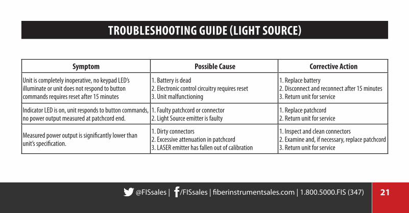
Symptom Possible cause corrective action
Unit is completely inoperative, no keypad LED’s illuminate or unit does not respond to button commands requires reset after 15 minutes
1. Battery is dead2. Electronic control circuitry requires reset 3. Unit malfunctioning
1. Replace battery2. Disconnect and reconnect after 15 minutes3. Return unit for service
Indicator LED is on, unit responds to button commands, no power output measured at patchcord end.
1. Faulty patchcord or connector2. Light Source emitter is faulty
1. Replace patchcord2. Return unit for service
Measured power output is significantly lower than unit’s specification.
1. Dirty connectors2. Excessive attenuation in patchcord3. LASER emitter has fallen out of calibration
1. Inspect and clean connectors2. Examine and, if necessary, replace patchcord3. Return unit for service
trouBLeShooting guiDe (Light Source)

1.800.5000.FIS (347) | fiberinstrumentsales.com | @FISsales | /FISsales22
Symptom Possible cause corrective action
LCD display is blank, unit won’t turn on1. Battery is dead2. Electronic control circuitry requires reset 3. Unit malfunctioning
1. Replace battery2. Disconnect and reconnect after 15 minutes3. Return unit for service
LCD display reads significantly below expected power level
1. Photodetector lens dirty2. Patchcord connector ends dirty or patchcord faulty
1. Remove adapter and clean lens2. Clean connectors, replace patchcord if necessary3. Check input Light Source
LCD display is on, unit does not respond to button commands 1. Electronic control circuitry requires reset
1. Disconnect battery and reconnect after 15 minutes
trouBLeShooting guiDe (Power Meter) calibration and recalibration
1.800.5000.FIS (347) | fiberinstrumentsales.com | @FISsales | /FISsales @FISsales | /FISsales | fiberinstrumentsales.com | 1.800.5000.FIS (347) 23
Long term StorageRemoving the battery is highly recommended if the unit is to be stored without being used for periods of time exceeding one month.
The FIS Hand Held Power Meter is calibrated to NIST (National Institute of Standards and Technology) traceable standards. With a readout precision (or resolution) of 0.1dBm, the meter is designed to provide an accuracy of ±0.3dBm. A certificate of calibration is enclosed with the unit. Please note that it is certified for one year. FIS recommends recalibration annually, which is performed for a nominal fee.
Products manufactured by FIS are designed to provide accurate and dependable operation. However, if a problem develops, a full one-year warranty is provided. Warranty coverage includes parts and labor, but does not cover damage due to misuse or harsh treatment. Reminder: installing batteries backward or attempting to use any alternative power supply may seriously damage the unit. FIS test equipment contains no user-serviceable parts; tampering with internal circuitry in any way voids the warranty. Warranty is nontransferable. If repair is required, simply call an FIS agent for return instructions and a RMA (Return Merchandise Authorization) number at 315.736.2206.
calibration and recalibration warranty
1.800.5000.FIS (347) | fiberinstrumentsales.com | @FISsales | /FISsales24
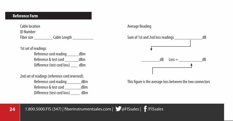
Cable locationID NumberFiber size ________ Cable Length _________
1st set of readings: Reference cord reading _____dBm Reference & test cord ______dBm Difference (test cord loss) ___ dBm
2nd set of readings (reference cord reversed): Reference cord reading ______dBm Reference & test cord _______dBm Difference (test cord loss) ____ dBm
Average Reading
Sum of 1st and 2nd loss readings ____________dB
________dB Loss = __________dB
This figure is the average loss between the two connectors
reference Form

1.800.5000.FIS (347) | fiberinstrumentsales.com | @FISsales | /FISsales
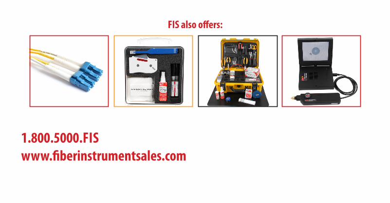
1.800.5000.FiSwww.fiberinstrumentsales.com
FiS also offers:


![Untitled-4 [] · Standard lamineret (8 meter / *4 meter) Neon lamineret - 5 meter Mat lamineret - 8 meter / **5 meter) Metallic lamineret - 8 meter Ulamineret - 8 meter Fleksibel](https://img.pdfslide.net/doc/110x75/5f3a768af7b8e86a6437cff7/untitled-4-standard-lamineret-8-meter-4-meter-neon-lamineret-5-meter.jpg)