Embed Size (px)
Citation preview

Power Modular Concept PMC 40
FRIEDHELM L O H GROUP
Power range: 10 - 40 kW per rack
PMC 40 highlights at a glance • PMC 40 with Safe-Swap Modules
For premium power protection availability
• Low total Cost of Ownership (TCO) Cost saving during entire life-cycle
• Flexibility/Scalability Ease of power upgrade, pay as you grow
• Enhanced Serviceability Rapid fault recovery
R i t t a l GmbH & Co. KG Auf dem Stützelberg D – 3 5 7 4 5 H e r b o r n Deutschland Email: [email protected] http://www.rittal.de Service - Tel.: (+49) - (0)2772 / 505 - 9052 Service - Fax: (+49) - (0)2772 / 505 - 2319
Technical Specifications
A 42345 00 IT74

1. Table of Contents 1. Table of Contents .................................. ..............................................................................................................2 2. PMC 40 System Description.......................... .....................................................................................................3 3. Technical Characteristics PMC 40................... ..................................................................................................4
3.1. Mechanical Characteristics PMC 40 Subracks ........ .............................................................................4 3.2. Input Characteristics.............................. ...................................................................................................5
3.2.1. GRAPH: Input PF versus % Load...........................................................................................................6 3.2.2. GRAPH: Input Distortion THDI versus % Load.......................................................................................6
3.3. Battery Characteristics ............................ .................................................................................................7 3.4. Output Characteristics............................. .................................................................................................7
3.4.1. GRAPH: AC – AC Efficiency with Linier load @ cosphi 1 ......................................................................8 3.4.2. GRAPH: Output Power in KW and KVA versus cosphi .........................................................................8
3.5. Environmental Characteristics ...................... ..........................................................................................9 3.6. Standards.......................................... .........................................................................................................9 3.7. Communication ...................................... .................................................................................................10
3.7.1. Power Management Display (PMD) .....................................................................................................10 3.7.2. MIMIC Diagram.....................................................................................................................................10 3.7.3. Display ..................................................................................................................................................10 3.7.4. Customer Interfaces Terminals X1…X2 .............................................................................................11 3.7.5. Customer Inputs Dry Ports Terminal block X2.....................................................................................11 3.7.6. Customer Outputs Dry Ports Terminal blocks X1...............................................................................11 3.7.7. Battery Autonomy of PMC 40 Typ 1 ,Typ 2, Typ 3, Typ 4 ....................................................................12
3.8. Installation Planning .............................. .................................................................................................12 3.8.1. Heat Dissipation per Module with non-Linear Load..............................................................................12
3.9. Wiring and Block Diagrams for all Frames and Module s....................................................................13 3.9.1. Terminal Connections Overview PMC 40 Subracks.............................................................................13 3.9.2. Single Feed Input ..................................................................................................................................14 3.9.3. Single Feed Input / Cable Sections / PMC 40 Subracks ......................................................................14 3.9.4. Dual Feed Input ....................................................................................................................................15 3.9.5. Dual Feed Input / Cable Sections / Rack Independent PMC 40 Subracks ..........................................15

PMC 40 System Description
www.rimatrix5.com Technical Specifications PMC40 Page 3/15
Modifications reserved
EN 2. PMC 40 System Description
In environments that demand zero downtime, continuous power protection availability is essential. In order to respond to today’s dynamic IT and process-related environments that experience daily change through new server technologies, migration and centralization, resilient and easily adaptable power protection concepts are required. The Power Modular Concept is the foundation for continuous power protection availability of network-critical infrastructures in enterprise data centers where business continuity has paramount importance and in process control environment where manufacturing continuity is essential. Rittal PMC 40 is a second generation high-power-density (HPD), leading-edge double-conversion power protection technology that has standardized on a modular component approach which helps speed deployment, improve adaptability and increase system availability while reducing total cost of ownership. It has a unique on-demand architecture that integrates the power rack, power distribution unit, back-up battery rack and management solutions to allow easy selection of optimized configurations. The PMC 40 provides highest availability, unmatched flexibility and at the same time lowest cost of ownership in IT environments. This Technical Specification provides detailed technical information on the mechanical, electrical and environmental performance of the PMC 40 model types that can support to give answers to tender and end-user requirements. The PMC family was designed to respond to the most stringent safety, EMC and other important UPS standards. PMC 40 is a rack independent modular design offering 4-types of Rack Independent Frames for a wide range of power requirements: PMC 40 Subracks:
• Typ 1 (10 kW) • Typ 2 (10 – 20 kW) • Typ 3 (10 – 20 kW) • Typ 4 (20 – 40 kW)
PMC 40 Modules types:
• PMC 40 UPS-Module 10 kW • PMC 40 UPS-Module 20 kW
Key Features of PMC 40:
• Highest Availability Near-zero down time Modular, Decentralized Parallel Architecture (DPA)
• High Power Density Space-saving of expensive floor space Small Footprint
• Unity Output Power Factor No de-rating for loads with Unity PF Full power for loads with unity PF
• Highest Efficiency even with partial loads Energy cost saving during UPS-life-cycle Efficiency = 94.5 - 95.5% for loads 25 - 100% (depending on Module power and type of load)
• Very low input current distortion THDi Gen-set power and installation cost saving THDi = < 3% for loads of 100 – 25 %

Technical Characteristics PMC 40
www.rimatrix5.com Technical Specifications PMC40 Page 4/15
Modifications reserved
EN
3. Technical Characteristics PMC 40
3.1. Mechanical Characteristics PMC 40 Subracks
PMC 40 Typ 1 Typ 2 Typ 3 Typ 4
PMC 40 Subrack
Configuration accommodates:
Max.
1 module (10kW)
with 40 x 7Ah batteries
1 module (10 or 20kW)
with 80 x 7Ah batteries
2 modules (10kW)
with 80 x 7Ah batteries
2 modules (10 or 20kW)
with 160 x 7Ah batteries
Max. Subrack connection kW 10 20 20 40
Dimensions (WxHxD) mm 485x487x740
(11 HU) 485x665x740
(15 HU) 485x798x740
(18 HU) 485x1153x740
(26 HU)
Weight of Empty Frame w/o modules and w/o batteries
kg 40 56 66 93
Weight of Frame with modules and w/o batteries
kg 59
(with 1 Module) 75 up to 78
(with 1 Module) 104
(with 2 Modules) 131 up to 137
(with 2 Modules)
MODULES
UPS-Module 10 kW UPS-Module 20 kW
Output Active Rated Power kW 10 20 Number of 12V Battery Blocks
No. 40 / 80 40 / 80
Dimensions (WxHxD) mm 448 (488) x 132 x 540
(3 HU)
Weight UPS-Module kg 18.6 21.5
Color Front : RAL 9005

Technic al Characteristics PMC 40
www.rimatrix5.com Technical Specifications PMC40 Page 5/15
Modifications reserved
EN
3.2. Input Characteristics
Module Range PMC 40 UPS-Modules 10 and 20 kW
Module Type UPS Module 10 kW UPS Module 20 kW
Output Rated Power per Module cosφ 0.8 kVA 10 20 Output Rated Power per Module cosφ 1.0 kW 10 20 Nominal Input Voltage V 3x380/220V+N, 3x400V/230V+N, 3x415/240V+N
Input Voltage Tolerance (ref to 3x400/230V) for Loads in %: V
(-23%/+15%) 3x308/177 V to 3x460/264 V for <100 % load (-30%/+15%) 3x280/161 V to 3x460/264 V for < 80 % load (-40%/+15%) 3x240/138 V to 3x460/264 V for < 60 % load
Input Frequency Hz 35 – 70
Input Power Factor PF=0.99 @ 100 % load
Inrush Current A max. In
Input Distortion THDI Sine-wave THDi = < 3 % @ 100% load
Max. Input Power with rated output power and charged battery per Module (output Cosφ = 1.0)
kW 10.5 21
Max. Input Current with rated output power and charged battery per Module (output Cosφ = 1.0)
A 15.2 30.4
Max. Input Power with rated output power and discharged battery per Module (output Cosφ = 1.0)
kW 11.6 23
Max. Input Current with rated output power and discharged battery per Module (output Cosφ = 1.0)
A 16.8 33.6

Technical Characteristics PMC 40
www.rimatrix5.com Technical Specifications PMC40 Page 6/15
Modifications reserved
EN
Input power factor versus load (Leading)
0.990.990.9850.96
0
0.2
0.4
0.6
0.8
1
25 50 75 100
load %
3.2.1. GRAPH: Input PF versus % Load
3.2.2. GRAPH: Input Distortion THDI versus % Load
Input Current Distortion THDi
4.0 3.73.4
3.0
1.52.02.53.03.54.04.55.05.56.0
25 50 75 100
Load %

Technic al Characteristics PMC 40
www.rimatrix5.com Technical Specifications PMC40 Page 7/15
Modifications reserved
EN
3.3. Battery Characteristics
Module Range PMC 40 UPS-Modules 10 and 20 kW
Module Type UPS-Module 10 kW UPS-Module 20 kW
Variable Number of 12V Battery Blocks No. 40 / 80 40 / 80
Maximum Battery Charger Current A 4 A 4 A
Battery Charging Curve Ripple free ; IU (DIN 41773)
Temperature compensation Standard (temp. sensor optional)
Battery Test Automatic and periodically (adjustable)
Battery Type Maintenance free VRLA or NiCd
3.4. Output Characteristics
Module Range PMC 40 UPS-Modules 10 or 20 kW
Module Type UPS-Module 10 kW UPS-Module 20 kW
Output Rated Power per Module cosphi 0.8 kVA 10 20 Output Rated Power per Module cosphi 1.0 kW 10 20
Output Current In @ cosphi 1.0 (400 V) A 14.5 29
Output Rated Voltage V 3x380/220V or 3x400/230V or 3x415/240V
Output Voltage Stability % Static: < +/- 1% Dynamic (Step load 0%-100% or 100%-0%) < +/- 4%
Output Voltage Distortion % With Linear Load < 1.5% With Non-linear Load (EN62040-3:2001) < 3%
Output Frequency Hz 50 Hz or 60 Hz
Output Frequency Tolerance % Synchronized with mains < +/- 2 % (selectable for bypass operation) or < +/- 4 % Free running +/- 0.1 %
Bypass operation At Nominal Input voltage of 3x400 V +/- 15% or 190 V to 264 V ph-N
Permissible Unbalanced Load (All 3 phases regulated independently)
% 100%
Phase Angle Tolerance (With 100 % Unbalanced load) Deg. +/- 0 deg.
Overload Capability on Inverter % 125 % load 10 min. 150 % load 60 sec.
Output short capability (RMS) A Inverter : 3 x In during 250 ms Bypass : 10 x In during 10 ms
Crest - Factor 3 : 1
Technical Characteristics PMC 40
www.rimatrix5.com Technical Specifications PMC40 Page 8/15
Modifications reserved
EN
3.4.1. GRAPH: AC – AC Efficiency with Linier load @ cosphi 1 Efficiency up to 1 % higher with output PF cosphi 0.8 Details refer to paragraph 10.7 Environmental Characteristics
Linear Load (cosphi=1)
95.595.59594.5
707580859095
100
25 50 75 100 Load %
%
UPS Module10/20kW
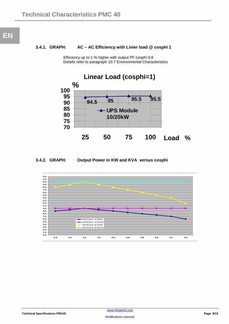
3.4.2. GRAPH: Output Power in KW and KVA versus co sphi
0.0
1.0
2.0
3.0
4.0
5.0
6.0
7.0
8.0
9.0
10.0
11.0
12.0
13.0
14.0
15.0
16.0
17.0
18.0
19.0
20.0
21.0
22.0
0.9 1.0 1.0 1.0 0.9 0.9 0.8 0.8 0.7 0.6
UPSCALE 10 (kW)
UPSCALE 10 (kVA)
UPSCALE 20 (kW)
UPSCALE 20 (kVA)

Technic al Characteristics PMC 40
www.rimatrix5.com Technical Specifications PMC40 Page 9/15
Modifications reserved
EN
3.5. Environmental Characteristics
Module Range PMC 40 UPS-Modules 10 or 20 kW
Module Type UPS-Module 10 kW UPS-Module 20 kW
Audible Noise with 100% / 50% Load dBA 55 / 49 57 / 49
Operation temperature °C 0 – 40
Ambient Temperature for Batteries (recommended) °C 20 – 25
Storage Temperature °C -25 - +70
Battery Storage Time at Ambient Temperature Max. 6 months
Max. altitude (above sea level) m 1000m (3300ft) without de-rating
Meter above sea level (m / ft) De-Rating Factor for Power
1500 / 4850 0.95 2000 / 6600 0.91 2500 / 8250 0.86
De-rating factor for use at altitudes above 1000m sea level according ( IEC 62040-3)
3000 / 9900 0.82
Relative Air-humidity Max. 95% (non-condensing)
Accessibility Totally front accessibility for service and
maintenance (no need for side, top or rear access)
Positioning Min. 20 cm rear space (required for fan)
Input and Output Power Cabling From the bottom on the front
Efficiency AC-AC up to (at cosphi 1.0) (depending on Module power)
% Load : 100 % 75 % 50% 25% M 20 : 95.5% 95.5% 95% 94.5% M 10 : 95.5% 95.5% 95% 94.5%
Efficiency with Linear Load at cosφ =0.8ind
Efficiency Non-linear Load (EN 62040-1-1:2003)
Typically up to 1 % higher of above values
Typically up to 1 % lower of above values
Eco-Mode efficiency at 100% load % 98 %
3.6. Standards
Safety EN 62040-1-1:2003, EN 60950-1:2001/A11:2004
Electromagnetic Compatibility EN 62040-2:2005, EN61000-3-2:2000,
EN61000-3-3:1995/A1:2001, EN61000-6-2:2001
EMC Classification for UPS-Module 10 kW UPS-Module 20 kW
Emission Class C1 C2
Immunity Class C1 C3
Performance EN62040-3:2001
Product certification CE
Degree of protection IP 20

Technical Characteristics PMC 40
www.rimatrix5.com Technical Specifications PMC40 Page 10/15
Modifications reserved
EN 3.7. Communication
Power Management Display (PMD) 1 LCD display for each module
RJ45 Plug (Not used) RJ45 Plug (for future options)
Customer Interfaces : Outputs DRY PORT X 2
5 voltage free contacts For remote signaling and automatic computer shutdown
Customer Interfaces : Inputs DRY PORT X1
1 x Remote Shut down [EMERGENCY OFF (Normally closed)] 2 x Programmable Customer’s Inputs (1st default as GEN-ON (Normally open) (2nd free Programmable Customer’s Inputs (Normally open) 1 x Temp. Sensor for Battery Control 1 x 12 Vdc output (max. 200mA)
Serial ports RS232 on Sub-D9 1 x system frame For monitoring and integration in network management
USB 1x For monitoring and software management
Slot for SNMP SNMP card (optional) For monitoring and integration in network management
3.7.1. Power Management Display (PMD) The user-friendly PMD consists of three parts the MIMIC DIAGRAM, CONTROL KEYS and LCD that provides the necessary monitoring information about the UPS.
3.7.2. MIMIC Diagram The mimic diagram serves to give the general status of the UPS. The LED-indicators show the power flow status and in the event of mains failure or load transfer from inverter to bypass and vice-versa the corresponding LED-indicators will change color from green (normal) to red (warning). The LED’s LINE 1 (rectifier) and LINE 2 (bypass) indicate the availability of the mains power supply. The LED’s INVERTER and BYPASS if green indicate which of the two are supplying power to the critical load. When the LED-indicator BATTERY is lit it means that the battery due to mains failure is supplying the load. The LED-indicator ALARM is a visual indication of any internal or external alarm condition. At the same time the audible alarm will be activated.
3.7.3. Display The 2 x 20 character LCD simplifies the communication with the UPS. The menu driven LCD enables the access to the EVENT REGISTER, or to monitor the input and output U, I, f, P, Autonomy Time and other Measurement’s, to perform commands like start-up and shut-down of INVERTER or load transfer from INVERTER to BYPASS and vice-versa and finally it serves for the DIAGNOSIS (SERVICE MODE) for adjustments and testing (for more details see the USER MANUAL of PMC 40).
Power Management Display (PMD) of PMC 40

Technic al Characteristics PMC 40
www.rimatrix5.com Technical Specifications PMC40 Page 11/15
Modifications reserved
EN 3.7.4. Customer Interfaces Terminals X1…X2
3.7.5. Customer Inputs Dry Ports Terminal block X2 Connection of Remote Shut down facilities, Generator Operation, Customers specials (see User Manual Section OPTIONS)
3.7.6. Customer Outputs Dry Ports Terminal blocks X1 Provision of signals for the automatic and orderly shutdown of servers, AS400 or automation building systems. All voltage free contacts are rated 60 VAC max. and 500 mA max.: All the interfaces are connected to Phoenix Spring terminals with wires : 0.5 mm2
Block Terminal Contact Signal On Display Function
X2 / 1 NO MAINS_OK Mains Present
X2 / 2 NC ALARM Mains Failure
X2 / 3 C Common
X2 / 4 NO LOAD_ON_INV Load on Inverter
X2 / 5 NC Message (Load on Mains bypass)
X2 / 6 C Common
X2 / 7 NO BATT_LOW Battery Low
X2 / 8 NC ALARM Battery OK
X2 / 9 C Common
X2 / 10 NO LOAD_ON_MAINS Load on bypass (Mains)
X2 / 11 NC Message (Load on Inverter)
X2 / 12 C Common
X2 / 13 NO COMMON_ALARM Common Alarm (System)
X2 / 14 NC ALARM NO Alarm Condition
X2
X2 / 15 C Common
X1 / 1
IN + 12Vdc Customer IN 1 (default as Generator Operation )
X1 / 2
GND GND (NC = Generator ON)
X1 / 3
IN + 12Vdc Customer IN 2
X1 / 4
GND GND (Function on request, to be defined)
X1 / 5
IN
+
3.3Vdc Temperature Battery
X1 / 6
GND GND (If connected , the battery charger current if depending of the battery temp.)
X1 / 7
IN + 12Vdc Remote Shut down
X1 / 8
GND GND
(Do not remove the factory mounted bridge until external Remote Shut
down is connected)
X1 / 9
IN + 12Vdc 12 Vdc sourse
X1
X1 / 10
GND GND (max. 200 mA load)
Phoenix Spring Terminals (X1…X2) Connection

Technical Characteristics PMC 40
www.rimatrix5.com Technical Specifications PMC40 Page 12/15
Modifications reserved
EN
3.7.7. Battery Autonomy of PMC 40 Typ 1 ,Typ 2, Typ 3, Typ 4
Autonomy Time PMC 40 Configuration Battery 50% Load 100% Load
Typ 1 1x 10 kW 40 x 7Ah 14 Min. 6 Min.
1x 10 kW 35 Min. 15 Min. Typ 2
1x 20 kW 80 x 7Ah
15 Min. 5 Min.
Typ 3 2x 10 kW 80 x 7Ah 14 Min. 6 Min.
2x 10 kW 35 Min. 16 Min. Typ 4
2x 20 kW 160 x 7Ah
15 Min. 5 Min.
3.8. Installation Planning
Clearances X Y
Minimum 200mm 900 mm
3.8.1. Heat Dissipation per Module with non-Linear Load
Module Range PMC 40 UPS-Module 10 or 20kW
Module Type PMC 40 UPS-Module 10kW PMC 40 UPS-Module 20kW
Heat Dissipation with 100% Non-linear Load per Module (EN 62040-1-1:2003) W 450 900
Heat Dissipation with 100% Non-linear Load per Module (EN 62040-1-1:2003)
BTU/h 1552 3104
Airflow (25° - 30°C) with Non-linear Load per Module (EN 62040-1-1:2003)
m3/h 150 150
UPS
Frames
X
Battery Cabinet
UPS
Frames
X
Figure 1: UPS space recommendation Figure 2 : : UPS + Battery space recommendation
Open Doors Y
Open Doors Y

Technic al Characteristics PMC 40
www.rimatrix5.com Technical Specifications PMC40 Page 13/15
Modifications reserved
EN
3.9. Wiring and Block Diagrams for all Frames and M odules
The customer has to supply the wiring to connect the UPS to the local power source. The installation inspection and initial start up of the UPS and extra battery cabinet must be carried out by a qualified service personnel such as a licensed service engineer from the manufacturer or from an agent authorized by the manufacturer. More details and procedure are mentioned in the user manual.
3.9.1. Terminal Connections Overview PMC 40 Subrack s
FRAME TYPE Terminals (T) Connection Bar (B)
Battery Earth PE
Separate. Battery (+ / N / - )
Common Battery (+ / N / - )
Input Bypass 3+N
Input Rectifier 3+N+PE
Output load 3+N+PE
PMC 40 16/25mm2 (T) 2x (3 x 10/16mm2) (T)
3 x M5 (B) 4 x 16/25 mm2 (T) 5 x 16/25 mm2 (T) 5 x 16/25 mm2 (T)
PMC 40 Series
Batt. Input Output

Technical Characteristics PMC 40
www.rimatrix5.com Technical Specifications PMC40 Page 14/15
Modifications reserved
EN
3.9.2. Single Feed Input
Cable Sections and Fuse Ratings recommended. Alternatively, local standards to be respected
STANDARD VERSION (SINGLE FEED INPUT)
3.9.3. Single Feed Input / Cable Sections / PMC 40 Subracks
Input 3x400V/230V Output 3x400V/230V @ cosphi 1.0 Battery
Cable E (mm2) for CBAT UPScale 120 or
200 ONLY + / N / -
Subrack type
Load in KW Fuse A
(Agl/CB)
Cable A (mm2)
(IEC 60950-1:2001)
Max. Input Current with battery charging (A)
Cable D (mm2)
(IEC 60950-1:2001)
I nom (A)
Fuse E + / N / -
(Agl/CB) Com.
Battery Sep. Battery
PMC 40 Typ 1 20 3x40A 5x6 27 5x6 29 A 3x63A 3x10 PMC 40 Typ 2 20 3x40A 5x6 27 5x6 29 A 3x63A 3x10 PMC 40 Typ 3 40 3x80A 5x16 68 5x16 58 A 3x100A *1 3x25 *1 2x(3x10) PMC 40 Typ 4 40 3x80A 5x16 68 5x16 58 A 3x100A *1 3x25 *1 2x(3x10)
Frame
Maintenance Bypass IA1
Cable D
Load 3x400/230 V
UP
S m
odul
e 1
F1
F2
Static Switch
Inverter
Rectifier
MAINS 3x400/230V Fuse Cable A
Cable E Fuse
E U
PS
mod
ule
2…4
F1
F2
Static Switch
Inverter
Rectifier
UP
S m
odul
e 5
F1
F2
Static Switch
Inverter
Rectifier
M1 M2 – M5 M6

Technic al Characteristics PMC 40
www.rimatrix5.com Technical Specifications PMC40 Page 15/15
Modifications reserved
EN
3.9.4. Dual Feed Input
Cable Sections and Fuse Ratings recommended. Alternatively, local standards to be respected
VERSION (DUAL FEED INPUT)
3.9.5. Dual Feed Input / Cable Sections / Rack Inde pendent PMC 40 Subracks
Input 3x400V/230V Bypass 3x400V/230V
Output 3x400V/230V @ cosphi 1.0
Battery
Cable E (mm2) for CBAT UPScale 120 or 200 ONLY
+ / N / -
Subrack type
Load in KW
Fuse B
(Agl/CB)
Cable B (mm2)
(IEC 60950-1:2001)
Max. Input Current
with battery charging
(A)
Fuse C
(Agl/CB)
Cable C (mm2) (IEC
60950-1:2001)
Cable D (mm2) (IEC
60950-1:2001)
I nom Fuse E +/N/-
(Agl/CB) Com.
Battery Sep.
Battery
PMC 40 Typ 1 20 3x40A 5x6 27 3x40A 4x6 5x6 29 A 3x63A 3x10
PMC 40 Typ 2 20 3x40A 5x6 27 3x40A 4x6 5x6 29 A 3x63A 3x10
PMC 40 Typ 3 40 3x80A 5x16 68 3x80A 4x16 5x16 58 A 3x100A *1 3x25 *1 2x(3x10)
PMC 40 Typ 4 40 3x80A 5x16 68 3x80A 4x16 5x16 58 A 3x100A *1 3x25 *1 2x(3x10)
MAINS 3x400/230V
Maintenance Bypass IA1
UP
S m
odul
e 1
F1
F2
Static Switch
M1
Inverter
Rectifier Cable E Fuse
E
UP
S m
odul
e 2…
4
F1
F2
Static Switch
M2-M5
Inverter
Rectifier
UP
S m
odul
e 5
F1
F2
Static Switch
M6
Inverter Module
Rectifier
Fuse B Cable B
Fuse C Cable C
Frame
Cable D
Load 3x400/230 V