Embed Size (px)
Citation preview

U K A S
QUALITY
MANAGEMENTISO 9001008
CSA
E
E
n
e
r
g
y
E
f
f
i
c
i
e
n
t
Power BehindThe Drive
M
EPAct
otorsNEMA
Electric MotorsPOWER TECHPOWER TECHPOWER TECH
Electric MotorsElectric Motors
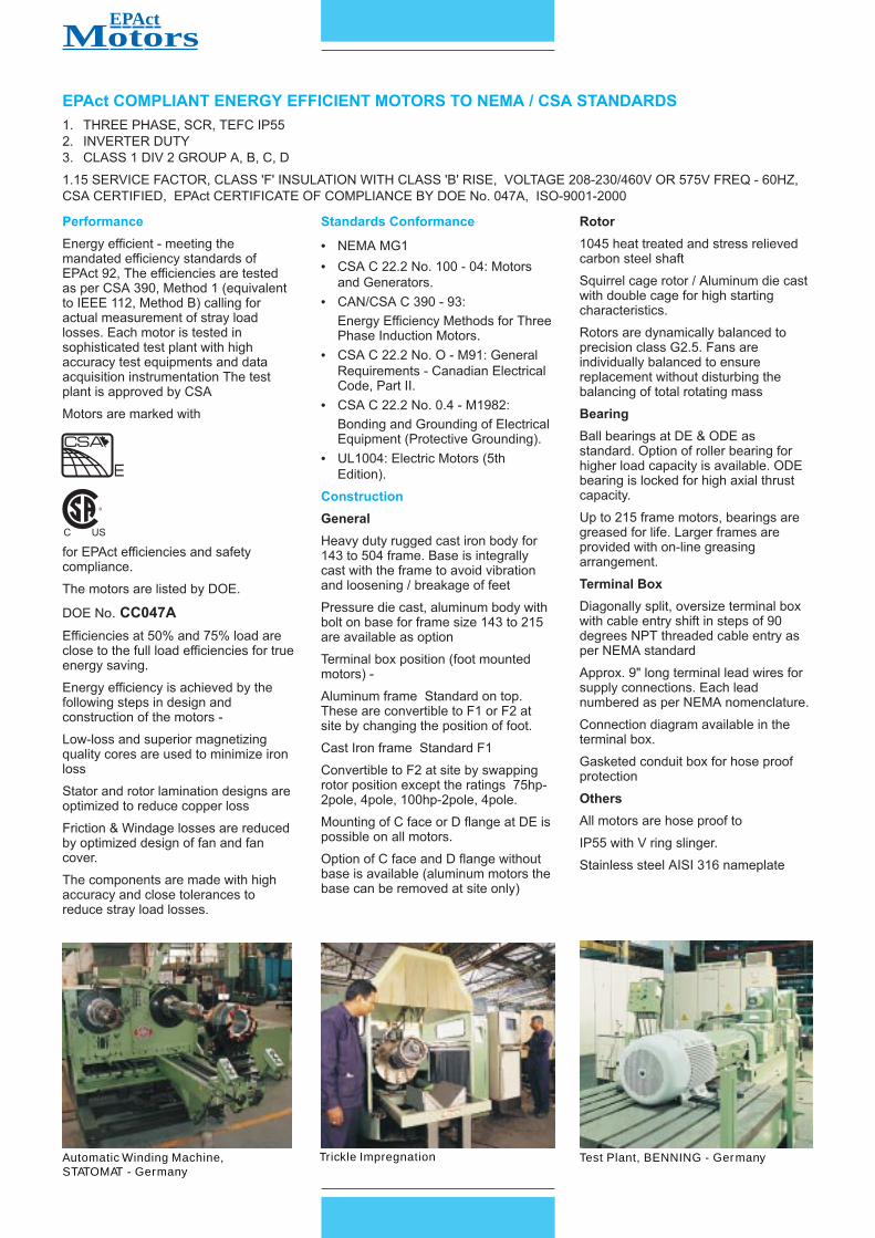
Trickle ImpregnationAutomatic Winding Machine,STATOMAT - Germany
Test Plant, BENNING - Germany
EPAct COMPLIANT ENERGY EFFICIENT MOTORS TO NEMA / CSA STANDARDS
1. THREE PHASE, SCR, TEFC IP55
2. INVERTER DUTY
3. CLASS 1 DIV 2 GROUP A, B, C, D
1.15 SERVICE FACTOR, CLASS 'F' INSULATION WITH CLASS 'B' RISE, VOLTAGE 208-230/460V OR 575V FREQ - 60HZ,
CSA CERTIFIED, EPAct CERTIFICATE OF COMPLIANCE BY DOE No. 047A, ISO-9001-2000
Performance
Energy efficient - meeting the
mandated efficiency standards of
EPAct 92, The efficiencies are tested
as per CSA 390, Method 1 (equivalent
to IEEE 112, Method B) calling for
actual measurement of stray load
losses. Each motor is tested in
sophisticated test plant with high
accuracy test equipments and data
acquisition instrumentation The test
plant is approved by CSA
Motors are marked with
for EPAct efficiencies and safety
compliance.
The motors are listed by DOE.
DOE No
Efficiencies at 50% and 75% load are
close to the full load efficiencies for true
energy saving.
Energy efficiency is achieved by the
following steps in design and
construction of the motors -
Low-loss and superior magnetizing
quality cores are used to minimize iron
loss
Stator and rotor lamination designs are
optimized to reduce copper loss
Friction & Windage losses are reduced
by optimized design of fan and fan
cover.
The components are made with high
accuracy and close tolerances to
reduce stray load losses.
. CC047A
Standards Conformance
Construction
••
•
•
•
•
NEMA MG1
CSA C 22.2 No. 100 - 04: Motors
and Generators.
CAN/CSA C 390 - 93:
Energy Efficiency Methods for Three
Phase Induction Motors.
CSA C 22.2 No. O - M91: General
Requirements - Canadian Electrical
Code, Part II.
CSA C 22.2 No. 0.4 - M1982:
Bonding and Grounding of Electrical
Equipment (Protective Grounding).
UL1004: Electric Motors (5th
Edition).
Heavy duty rugged cast iron body for
143 to 504 frame. Base is integrally
cast with the frame to avoid vibration
and loosening / breakage of feet
Pressure die cast, aluminum body with
bolt on base for frame size 143 to 215
are available as option
General
Terminal box position (foot mounted
motors) -
Aluminum frame Standard on top.
These are convertible to F1 or F2 at
site by changing the position of foot.
Cast Iron frame Standard F1
Convertible to F2 at site by swapping
rotor position except the ratings 75hp-
2pole, 4pole, 100hp-2pole, 4pole.
Mounting of C face or D flange at DE is
possible on all motors.
Option of C face and D flange without
base is available (aluminum motors the
base can be removed at site only)
Rotor
Bearing
Terminal Box
Others
1045 heat treated and stress relieved
carbon steel shaft
Squirrel cage rotor / Aluminum die cast
with double cage for high starting
characteristics.
Rotors are dynamically balanced to
precision class G2.5. Fans are
individually balanced to ensure
replacement without disturbing the
balancing of total rotating mass
Ball bearings at DE & ODE as
standard. Option of roller bearing for
higher load capacity is available. ODE
bearing is locked for high axial thrust
capacity.
Up to 215 frame motors, bearings are
greased for life. Larger frames are
provided with on-line greasing
arrangement.
Diagonally split, oversize terminal box
with cable entry shift in steps of 90
degrees NPT threaded cable entry as
per NEMA standard
Approx. 9" long terminal lead wires for
supply connections. Each lead
numbered as per NEMA nomenclature.
Connection diagram available in the
terminal box.
Gasketed conduit box for hose proof
protection
All motors are hose proof to
IP55 with V ring slinger.
Stainless steel AISI 316 nameplate
MEPActotors
CSA
E

FRAME POLARITY DE BEARING ODE BEARING
364T / 365T 2/4/6/8 6313 C3 6313 C3
404T / 405T 2/4/6/8 6315 C3 6314 C3
444T / 445T / 447T 2 6314 C3 6314 C3
444T / 445T / 447T 4/6/8 6318 C3 6318 C3
504T 2 6315 C3 6315 C3
504T 4/6/8 6319 C3 6319 C3
FRAME POLARITY DE BEARING ODE BEARING
143T / 145T 2/4/6/8 6205ZZ 6205ZZ
182T / 184T 2/4/6/8 6306ZZ 6205ZZ
213T / 215T - AL 2/4/6/8 6308ZZ 6305ZZ
213T / 215T - CI 2/4/6/8 6308ZZ 6208ZZ
254T / 256T 2/4/6/8 6309 C3 6309 C3
284T / 286T 2/4/6/8 6310 C3 6310 C3
324T / 326T 2/4/6/8 6312 C3 6312 C3
Paint
Aluminum motors are Epoxy powder
coated in two tone colour
Cast Iron motors are liquid painted with
Synthetic Enamel paint on Alkyd based
high build Primer (ASTM Salt Spray life
>200 hrs)
Design
Voltage & Frequency
Insulation and Ambient temp
Service factor
Continuously rated, with design B to
NEMA standards for General
Applications.
Enclosure: totally enclosed fan cooled.
208-230/460V, 60 Hz, AC
or 575V, 60 Hz, AC. Motors can be
marked also for 190-380V 50hz
Class F insulation with class B
temperature rise on ambient of 104 F
(40 C).
1.15 service factor except for 208V
supply, when SF would be 1 and motor
0
0
Standard Specifications
efficiency may not meet the declared
value.
Motors are suitable for MGI Part 31
rating to use with VFD - 5:1 constant
torque and 10:1 variable torque speed
range. Speed range can be extended
with optional Blower kit
The motor winding insulation scheme is
suitable for 2000V spike resistance.
All motors can be marked for class 1
Div 2. Group A,B,C,D temperature
class T3. The motors are tested and
certified by CSA
NEMA C face, D flange with /
without foot
Motor leads terminated on a terminal
block in Terminal Box.
Thermisters, Thermostats, winding
RTDs, bearing temperature sensing
devices and separate terminal box
for these auxiliaries.
Inverter duty
Class 1 Div 2 marking
•
•
•
Options
• Motors for closed coupled pumps
upto 326 frame
Special Motors
NEMA D design Oil well Pump
motors, see details on last page.
•
BEARING REFRENCE
DIMENSIONS AND WEIGHTS
Product improvement is a continuous process. Hence datagiven in this catalogue is subject to change without intimation.
MEPActotors
FRAME PACKINGNET WT GR WT VOLWT.(lb) WT. (lb) (cu. in.)
CAST IRON FRAME184TC/FT CARTON 86 97 3440213T WOODEN CRATE 150 172 5858213TC/FT WOODEN CRATE 160 182 5858215T WOODEN CRATE 174 196 5858215TC/FT WOODEN CRATE 184 206 5858254T WOODEN CRATE 267 405 15500256T WOODEN CRATE 315 453 15500284T WOODEN CRATE 383 563 19528286T WOODEN CRATE 450 607 19528324T WOODEN CRATE 560 810 44547326T WOODEN CRATE 592 843 44547364T WOODEN BOX 770 990 44547365T WOODEN BOX 836 1087 44547405T WOODEN BOX 1100 1410 64685444T WOODEN BOX 2323 2873 118386445/447T WOODEN BOX 2486 3036 118386504T WOODEN BOX 2640 3256 137303
FRAME PACKINGNET WT GR WT VOLWT.(lb) WT. (lb) (cu. in.)
ALUMINIUM FRAME143T CARTON 33 38 1665145T CARTON 40 45145TC/FT CARTON 44 49182T CARTON 64 70 2860182TC/FT CARTON 71 77184T CARTON 68 75184TC/FT CARTON 75 82213T WOODEN CRATE 110 132 5370213TC/FT WOODEN CRATE 119 141 5370215T WOODEN CRATE 117 139 5370215TC/FT WOODEN CRATE 125 147 5370CAST IRON FRAME143T CARTON 49 54 2000145T CARTON 55 60 2000145TC/FT CARTON 62 67 2000182T CARTON 77 88 3440182TC/FT CARTON 86 97184T CARTON 77 88
16651665
286028602860
34403440
AL - ALUMINIUM FRAME, CI - CAST IRON FRAME

Notes - Performance at 230V and 460V is applicable for 230/460V motors, suitably connected. Performance at 575V is for 575V motors.- FL - Full Load, LR - Locked Rotor, BD - Break Down- Minimum efficiencies shall be as per NEMA MG 1
MEPActotors
OUTPUT
P
FRAME
FL
FL AMPS EFFICIENCY % POWER TORQUE LOCKED ROTOR NEMA INE
O
RPM
FACTOR AMPS CODE
L
E Nominal FL LR BD
kW HP S 230V 460V 575V FL 3/4 FL 1/2 FL FL 3/4 FL 1/2 FL Ib-ft % % 230V 460V 575V Ib-ft
0.55 0.75 6 143T 1140 3.4 1.7 1.4 72.0 69.0 64.0 0.57 0.50 0.40 3.50 240 280 15 7.5 6 J 0.13
0.75 1 2 143T 3400 3.1 1.6 1.3 75.5 73.0 71.0 0.80 0.75 0.70 1.50 300 350 24 12 10 L 0.03
4 143T 1710 3.3 1.7 1.4 82.5 81.0 77.0 0.71 0.60 0.40 3.10 275 300 24 12 10 L 0.13
6 145T 1150 4.0 2.0 1.6 80.0 79.0 76.0 0.60 0.50 0.40 4.60 250 270 24 12 10 L 0.16
1.1 1.5 2 143T 3400 4.1 2.1 1.7 82.5 82.5 82.0 0.82 0.80 0.70 2.30 275 300 36 18 14.5 L 0.05
4 145T 1710 4.6 2.3 1.9 84.0 84.0 83.0 0.72 0.65 0.60 4.60 230 280 36 18 16 L 0.13
6 182T 1145 5.0 2.5 2.0 85.5 85.5 85.0 0.65 0.60 0.50 6.90 220 250 36 18 16 L 0.27
1.5 2 2 145T 3400 5.4 2.7 2.2 84.0 84.0 84.0 0.84 0.80 0.70 3.10 275 300 50 25 20 L 0.06
4 145T 1710 5.8 2.9 2.3 84.0 84.0 83.0 0.77 0.70 0.60 6.10 240 280 50 25 20 L 0.16
6 184T 1145 6.0 3.0 2.4 86.5 86.5 86.0 0.72 0.65 0.60 9.20 220 250 50 25 20 L 0.34
2.2 3 2 182T 3480 7.2 3.6 2.9 85.5 85.5 85.0 0.89 0.87 0.85 4.50 275 300 64 32 25 K 0.14
4 182T 1740 7.6 3.8 3.0 87.5 87.5 87.0 0.83 0.76 0.64 9.10 230 280 64 32 25 K 0.27
6 213T 1150 8.4 4.2 3.4 87.5 87.5 87.0 0.75 0.67 0.60 13.70 220 250 64 32 25 K 0.88
3.7 5 2 184T 3480 12.0 6.0 4.8 87.5 87.5 87.0 0.89 0.87 0.85 7.50 275 300 92 46 37 J 0.18
4 184T 1740 12.8 6.4 5.1 87.5 87.5 87.0 0.83 0.78 0.67 15.10 230 280 92 46 37 J 0.34
6 215T 1160 14.2 7.1 5.7 87.5 87.5 87.0 0.75 0.67 0.60 22.60 210 240 92 46 37 J 0.97
5.5 7.5 2 213T 3480 17.2 8.6 6.9 88.5 88.5 88.0 0.90 0.88 0.86 11.30 210 240 126 63 50 H 0.39
4 213T 1740 18.4 9.2 7.4 89.5 89.5 89.0 0.84 0.81 0.74 22.60 210 240 126 63 50 H 0.88
6 254T 1164 20.0 10.0 8.0 89.5 86.5 83.5 0.80 0.76 0.68 33.27 200 250 126 63 50 H 1.27
7.5 10 2 215T 3480 23.4 11.7 9.4 89.5 89.5 89.0 0.90 0.88 0.86 15.10 210 240 162 81 65 H 0.43
4 215T 1750 25.0 12.5 10.0 89.5 89.5 89.0 0.84 0.81 0.74 30.00 210 240 162 81 65 H 0.97
6 256T 1170 27.5 13.8 11.0 89.5 90.2 89.0 0.80 0.76 0.68 45.14 200 250 162 81 65 H 2.73
11 15 2 254T 3504 35.0 17.5 14.0 90.2 89.5 88.0 0.88 0.86 0.78 22.10 250 300 232 116 92.8 G 0.77
4 254T 1752 35.0 17.5 14.0 91.0 91.0 89.5 0.84 0.82 0.74 44.21 200 250 232 116 92.8 G 2.14
6 284T 1170 37.5 18.8 15.0 90.2 90.2 89.0 0.80 0.76 0.68 66.21 200 250 232 116 92.8 G 3.80
15 20 2 256T 3504 47.5 23.8 19.0 90.2 90.2 89.0 0.88 0.86 0.79 30.50 250 300 290 145 116 G 1.01
4 256T 1752 50.0 25.0 20.0 91.0 91.0 89.5 0.84 0.83 0.75 60.29 200 250 290 145 116 G 2.79
6 286T 1170 52.5 26.3 21.0 90.2 91.0 89.5 0.80 0.73 0.68 90.28 225 275 290 145 116 G 6.88
18.5 25 2 284TS 3504 57.5 28.8 23.0 91.0 91.0 89.5 0.88 0.86 0.79 37.18 275 325 365 182.5 146 G 1.25
4 284T 1770 60.0 30.0 24.0 92.4 91.7 90.0 0.84 0.80 0.72 73.60 200 250 365 182.5 146 G 4.81
6 324T 1170 60.0 30.0 24.0 91.7 91.7 90.0 0.84 0.82 0.73 111.35 200 250 365 182.5 146 G 10.03
22 30 2 286TS 3504 65.0 32.5 26.0 91.0 91.0 89.5 0.92 0.90 0.84 44.21 275 325 435 217.5 174 G 2.61
4 286T 1770 70.0 35.0 28.0 92.4 92.4 91.0 0.86 0.84 0.77 87.53 200 250 435 217.5 174 G 5.64
6 326T 1170 72.5 36.3 29.0 91.7 92.4 91.0 0.84 0.82 0.78 132.40 200 250 435 217.5 174 G 12.10
30 40 2 324TS 3528 92.5 46.3 37.0 91.7 91.7 90.0 0.90 0.89 0.87 59.88 200 250 580 290 232 G 4.75
4 324T 1770 90.0 45.0 36.0 93.0 93.0 91.0 0.89 0.86 0.78 119.36 250 300 580 290 232 G 9.61
6 364T 1176 95.0 47.5 38.0 93.0 93.0 91.0 0.85 0.82 0.73 179.64 200 250 580 290 232 G 21.25
37 50 2 326TS 3540 112.5 56.3 45.0 92.4 92.4 91.0 0.90 0.89 0.87 73.60 200 250 725 362.5 290 G 5.28
4 326T 1776 112.5 56.3 45.0 93.0 93.0 91.0 0.89 0.86 0.78 146.70 250 300 725 362.5 290 G 15.66
6 365T 1176 120.0 60.0 48.0 93.0 93.0 92.0 0.84 0.81 0.72 221.56 250 300 725 362.5 290 G 25.75
45 60 2 364TS 3546 130.0 65.0 52.0 93.0 93.0 91.0 0.94 0.92 0.88 89.37 225 275 870 435 348 G 11.09
4 364T 1776 135.0 67.5 54.0 93.6 93.6 92.0 0.89 0.86 0.78 178.43 250 300 870 435 348 G 18.56
6 405T 1164 142.5 71.3 57.0 93.6 93.0 91.0 0.85 0.81 0.73 272.24 200 250 870 435 348 G 28.5
55 75 2 365TS 3546 157.5 78.8 63.0 93.0 93.0 91.0 0.94 0.92 0.88 109.22 175 225 1085 542.5 434 G 16.55
4 365T 1770 165.0 82.5 66.0 94.1 94.1 92.0 0.89 0.86 0.82 218.82 200 250 1085 542.5 434 G 20.46
6 405T 1164 175.0 87.5 70.0 93.6 93.0 91.0 0.84 0.80 0.72 332.74 200 250 1085 542.5 434 G 34.25
75 100 2 405TS 3546 215.0 107.5 86.0 93.6 93.0 91.0 0.94 0.92 0.88 148.94 150 200 1450 725 580 G 20
4 405T 1770 232.5 116.3 93.0 94.5 94.1 92.0 0.86 0.82 0.74 298.39 200 250 1450 725 580 G 24.5
RTIA
WK
6 444T 1170 238 119 95 94.1 93.6 93 0.79 0.75 0.67 451.35 200 250 1450 725 580 G 14.12
93 125 2 444T 3550 266 133 106 94.5 94.1 93.5 0.88 0.84 0.76 184.46 150 200 1815 907.5 726 G 5.82
93 125 4 444T 1775 266 133 106 94.5 94.1 93.5 0.88 0.84 0.76 368.91 175 225 1815 907.5 726 G 11.62
93 125 6 445T 1170 280 140 112 94.1 93.6 93 0.83 0.79 0.71 559.67 200 250 1815 907.5 726 G 17
110 150 2 445TS 3550 312 156 125 94.5 94.1 93.5 0.89 0.85 0.77 218.17 150 200 2170 1085 868 G 5.82
110 150 4 445T 1775 318 159 127 95 94.5 94 0.87 0.83 0.75 436.35 175 225 2170 1085 868 G 11.62
110 150 6 447T 1170 340 170 136 95 94.5 94 0.81 0.77 0.69 661.98 200 250 2170 1085 868 G 18.98
150 200 2 447TS 3550 424 212 170 95 94.5 94 0.89 0.85 0.77 297.51 150 200 2900 1450 1160 G 6.98
150 200 4 447T 1775 432 216 173 95 94.5 94 0.87 0.83 0.75 595.02 175 225 2900 1450 1160 G 13.98
150 200 6 504T 1170 464 232 186 95 94.5 94 0.81 0.77 0.69 902.70 200 250 2900 1450 1160 G 29.85
185 250 2 504T 3550 553 277 221 95.4 95 94 0.88 0.84 0.76 366.93 150 200 3650 1825 1460 G 16.37
185 250 4 504T 1775 562 281 225 95 94.5 94 0.87 0.83 0.75 733.86 175 225 3650 1825 1460 G 24.97
185 250 6 504T 1170 589 294 236 95 94.5 94 0.83 0.79 0.71 1113.33 200 250 3650 1825 1460 G 29.85
2
2
approx.

ALUMINIUM FOOT MOUNTED
CAST IRON FOOT MOUNTED
C
2F
X
X
SECT. 'X X'
HD
GDES
B
SU
R
V
N-W
BA
P
A
J
4 HOLES OF H
2E
D
CABLE ENTRY SCREWEDFOR 'AA' B.S. CONDUITFOR CABLE GLAND
All dimensions are in inches. Please call forcertified drawing for engineering purpose.
MEPActotors
B
ALL DIMENSONS IN INCHES
C
ES
N-W
AB
A
J
f AA
f H
+.05
-.00
S
GD
R
f U
SECT.-XX
2F+/-.03
BA+/-.09
AF
D
HD
G
f
P
XF
KEY
2E+/-.03
F2 - MOUNT FOR
OIL WELL PUMP MOTORS
Frame Mounting Keyway Shaft Ext.
Size 2E 2F H BA
A B C D J P HD AA
S GD R ES V N-W U
143T
5.50
4.00
0.34 2.25 6.70 5.95
12.40
3.50 1.50 7.10 9.00 NPT ¾” 0.188 0.188 0.771 1.41 1.575 2.25 0.875
145T 5.00 13.40
182T
7.50
4.50
2.75 8.75 6.70 15.35 4.50 2.00 8.75 11.00 NPT ¾” 0.250 0.250 0.986 1.78 1.900 2.75 1.125
184T 5.50
0.41
213T
8.50
5.50
3.50 9.92
7.00
18.94 5.25 2.00 10.24 12.53 NPT 1” 0.312 0.312 1.201 2.41 2.560 3.38 1.375
215T 7.00 8.50
KEY
Frame A B C D 2E 2F G H J BA P HD U R N-W XF
S GD ES
AB AF AA
143T
6.614
5.00 12.683
3.50 5.50
4.00
0.511 0.34 1.377 2.25 7.48 -- 0.875 0.771 2.25
-
0.188 0.188 1.41 5.90 2.46 ¾
145T 5.984 13.667 5.00 4.00
182T
8.74
6.692 15.348
4.50 7.50
4.50
0.511 0.41 1.417 2.75 9.055 10.82 1.125 0.986 2.75
-
0.250 0.250 1.78 6.69 2.46 ¾
184T 6.692 16.332 5.50 4.50
213T
10.00
7.00 18.734
5.25 8.50
5.50
0.629 0.41 1.889 3.50 10.62 12.59 1.375 1.201 3.38
-
0.312 0.312 2.41 7.48 2.46 1
215T 8.50 20.309 7.00 5.50
256T 10.00 8.25
284TS 25.5
9.50
1.625 1.416 3.25
-
0.375 0.375 1.91
324TS 32.2
10.50
1.875 1.591 3.75
-
2.03
324T
15.00 14.0
33.7
8.00 12.5 1.00 0.66 2.6 5.25 16.85 18.9
2.125 1.845 5.25
0.500 0.500
3.91
13.19 2.83 2
364TS 31.23 1.875 1.591 3.75 - 0.500 0.500 2.03
364T
16.73 15.75
33.24
9.00 14.0 1.00 0.66 2.75 5.88 18.50 21.02
2.375 2.021 5.88 0.625 0.625 4.28
15.98 5.35 3
404TS
19.00 17.75
37.2
10.0 16.0 1.25 0.81 3.15 6.62 19.68 23.54
2.125 1.845 4.25
-
0.500 0.500 2.78
17.08 5.35 3
404T 40.2
10.75
444TS 46.25 10.75 2.375 2.02 4.75 0.625 0.625 3.03
444T
21.25 23.4
50.0
11.0 18.0
14.50
1.40 0.81 4.0 7.5 23.15 28.5
3.375 2.88 8.5
-
0.875 0.875 6.91
18.5 5.35 3
504T 23.5 30.0 52.36 12.5 20.0 16.00 1.49 1.25 4.33 8.5 23.15 28.5 3.625 3.134 10.63 - 0.875 0.875 8.64 18.5 5.35 3
254T
12.125 11.75 25.30 6.25 10.0
8.25
0.875 0.55 2.87 4.25 12.52 14.8 1.625 1.416 4.00
-
0.375 0.375 2.91 10.48 2.83 1¼
284T
13.70 12.75
26.94
7.00 11.0 0.875 0.55 3.3 4.75 13.86 16.5
1.875 1.591 4.62 0.500 0.500 3.28
11.25 2.83 1½
286TS 27.0 1.625 1.416 3.25
9.50
0.375 0.375 1.91
286T
13.70 12.75
28.44
7.00 11.0 11.0 0.875 0.55 3.3 4.75 13.86 16.5
1.875 1.591 4.62 0.500 0.500 3.28
11.25 2.83 1½
326TS 32.2 1.875 1.591 3.75 2.03
326T
15.00 14.0
33.7
8.00 12.5 12.0 1.00 0.66 2.6 5.25 16.85 18.9
2.125 1.845 5.25
10.5 0.500 0.500
3.91
13.19 2.83 2
11.25
365TS 33.00 1.875 1.591 3.75 0.500 0.500 2.03
365T
16.73 15.75
35.01
9.00 14.0 12.25 1.00 0.66 2.75 5.88 18.50 21.02
2.375 2.021 5.88
11.25
0.625 0.625 4.28
15.98 5.35 3
2.875 2.450 7.25 0.75 0.75 5.65
405TS
19.00 17.75
37.2
10.0 16.0 1.25 0.81 3.15 6.62 19.68 23.54
2.125 1.845 4.25
12.25
0.500 0.500 2.78
17.08 5.35 3
405T 40.2
13.75
2.875 2.450 7.25 0.75 0.75 5.65
445TS 46.25 12.75 2.375 2.02 4.75 0.625 0.625 3.03
445T
21.25 23.4
50.0
11.0 18.0
16.50
1.40 0.81 4.0 7.5 23.15 28.5
3.375 2.88 8.5
-
0.875 0.875 6.91
18.5 5.35 3
447TS 46.25 16.25 2.375 2.02 4.75 0.625 0.625 3.03
447T
21.25 23.4
50.0
11.0 18.0
20.00
1.40 0.81 4.0 7.5 23.15 28.5
3.375 2.88 8.5
-
0.875 0.875 6.91
18.5 5.35 3

Face Fixing Shaft and Keyway Overall
Frame
Size
AJ AK BB max BD max ØBF N U N-W R ES min S GD AB Ø P C HB XL AF KK
143TC
5.875 4.5 0.16 6.5
3/8-16
4 0.875 2.12 0.771 1.41 0.188 0.188 5.90 7.48
12.56
--
5.07 2.46
1×3/4”
145TC
13.55
182TC
7.25 8.5 0.25 9.0
1/2-13
4 1.125 2.62 0.986 1.78 0.25 0.25 6.69 9.05
15.21
--
5.07 2.46
1×3/4”
184TC
16.20
213TC
7.25 8.5 0.25 9.0
1/2-13
4 1.375 3.12 1.201 2.41 0.312 0.312 7.48 10.62
18.5
--
5.07 2.46
1×1”
215TC
20.04
254TC
7.25 8.5 0.25 10
1/2-13
4 1.625 4 1.416 2.91 0.375 0.375 10.48 12.52 25.3 16.57 6.49 2.83
1×1”
256TC
284TCS
284TC
286TCS
286TC
324TCS
324TC
11 12.5 0.25 14
5/8-11
4
2.125 5.25 1.845 3.91 0.500 0.500
13.19 16.85
33.7
21.93 6.49 2.83
1×2”
326TCS
326TC
364TCS
364TC
365TCS
365TC
404TCS
404TC
405TCS
405TC
444TCS
444TC
445TCS
445TC
447TC
447TCS
14
16.0 0.25 18.0
5/8-11
4 3.625 10.63 3.134 8.64 0.875 18.5 28.5 52.36 32.3 10.32 5.35 1×3”504TC 0.875
9.0 10.5 0.25 11.25
1/2-13
4
1.875 4.62 1.591 3.28 0.500 0.500
11.25 13.86
26.94
18.82 6.49 2.83 1×1.5”
1.625 3.25 1.416 1.91 0.375 0.375 25.57
9.0 10.5 0.25 11.25
1/2-13
4
1.875 4.62 1.591 3.28 0.500 0.500
11.25 13.86
28.44
18.82 6.49 2.83 1×1.5”
1.625 3.25 1.416 1.91 0.375 0.375 27.07
1.875 3.75 1.591 2.03 0.500 0.500 32.2
11 12.5 0.25 14
5/8-11
4
2.125 5.25 1.845 3.91 0.500 0.500
13.19 16.85
33.7
21.93 6.49 2.83
1×2”
1.875 3.75 1.591 2.03 0.500 0.500 32.2
11 12.5 0.25 14
5/8-11
8
2.375 5.88 2.021 4.28 0.625 0.625
15.98 18.5
35.01
24.33 10.32 5.35 1×3”
1.875 3.75 1.591 2.03 0.500 0.500 32.88
11 12.5 0.25 14
5/8-11
8
2.375 5.88 2.021 4.28 0.625 0.625
15.98 18.5
35.01
24.33 10.32 5.35 1×3”
1.875 3.75 1.591 2.03 0.500 0.500 32.88
11 12.5 0.25 15.5
5/8-11
8
2.875 7.25 2.450 5.65 0.75 0.75
17.08 19.68
40.2
27.08 10.32 5.35 1×3”
2.125 4.25 1.845 2.78 0.50 0.50 37.2
11 12.5 0.25 15.5
5/8-11
8
2.875 7.25 2.450 5.65 0.75 0.75
17.08 19.68
40.2
27.08 10.32 5.35 1×3”
2.125 4.25 1.845 2.78 0.50 0.50 37.2
14 16.0 0.25 18.0
5/8-11
8
3.375 8.5 2.88 6.91 0.875
18.5 23.15
50.0
32.3 10.32 5.35 1×3”
0.875
2.375 4.75 2.021 3.03 0.625 46.250.625
14 16.0 0.25 18.0
5/8-11
8
3.375 8.5 2.88 6.91 0.875
18.5 23.15
50.0
32.3 10.32 5.35 1×3”
0.875
2.375 4.75 2.021 3.03 0.625 46.250.625
14 16.0 0.25 18.0
5/8-11
8
3.375 8.5 2.88 6.91 0.875
18.5 23.15
50.0
32.3 10.32 5.35 1×3”
0.875
2.375 4.75 2.021 3.03 0.625 46.250.625
ALUMINIUM ‘ C’ TYPE FLANGE MOUNTED
450
C
2F
X
X
SECT. "X-X"
HD
GD
ES
BC
BD
AK
AH
BB
B
S
U
R
V
N-W
BA
P
A
J
4 HOLES OF Ø H
2E
D
CABLE ENTRY SCREWED
FOR 'AA' B.S. CONDUIT FOR
CABLE GLAND
BF HOLES ON AJ P.C.D.
EQUI-SPACED
CAST IRON ‘C’ TYPE FLANGE MOUNTED
ALL DIMENSONS IN INCHES
EARTHING TERMINALS
CABLE ENTRY 'KK'
BC=0+/-1MM
N-W
X
ES
X
BB
C +/-0.25
ECCENTRICITY
FLANGE FACE RUNOUT
& SHAFT RUNOUT
fP
f
AK
(R
AB
BE
T)
fB
D
XL
AF
AB
45
0
'N'-HOLES 'BF' AS SHOWN
ON 'AJ' PCD
f
S
GD
R
f U
SECT.-XX
EYE BOLT
WHEN REQD.
HB
MEPActotors
All dimensions are in inches. Please call forcertified drawing for engineering purpose.
FRAME
MOUNTING
KEYWAY
SHAFT EXT
.
FLANGE
BF B
O
LT
SIZE
2E 2F H BA
A B C D J P HD AA
S GD
R E
S
V N-W
U
A
J
AK BD BB B
C
AH N
O
. T
AP SIZE
PENETR
143TC
5.50
4.0
0.34 2.25 6.70 5.95
12.4
3.5 1.5 7.1 9.0 NPT ¾” 0.188 0.188 0.771 1.41 1.575 2.25 0.875 5.875 4.50 6.50 0.16 2.12
UNC 3/8”×16
0.56
145TC
5.0 13.4
0.12
182TC
7.50
4.50
2.75 8.75 6.70 15.35 4.5 2.0 8.75 11.0 NPT ¾” 0.25 0.25 0.986 1.78 1.9 2.75 1.125 2.62 4
184TC
5.50
7.250 8.50 9.00 0.25
UNC 1/2”×13
0.75
213TC
8.50
5.50
0.41
3.50 9.92
7.0
18.94 5.25 2.0 10.24 12.53
NPT 1”
0.312 0.312 1.201 2.41 2.56 3.38 1.375 0.25 3.12
215TC
7.0 8.5
Flange Fixing Shaft and Keyway Overall
Frame
Size
AJ AK BB max BD max ØBF BE N U AH R ES min S GD AB Ø P C HB XL AF KK
10.0 9.0 0.25 11 0.53 0.5 4 0.875 2.25 0.771 1.41 0.188 0.188 5.90 7.48
12.68
--
5.07 2.46
1×3/4”
13.66
10.0 9.0 0.25 11 0.53 0.5 4 1.125 2.75 0.986 1.78 0.25 0.25 6.69 9.05
15.34
--
5.07 2.46
1×3/4”
16.33
10.0 9.0 0.25 11 0.53 0.5 4 1.375 3.38 1.201 2.41 0.312 0.312 7.48 10.62
18.73
5.07 2.46
1×1”
20.30
12.5 11.0 0.25 14 0.81 0.75 4 1.625 4.0 1.416 2.91 0.375 0.375 10.48 12.52 25.3 16.57 6.49 2.83
1×1”
12.5 11.0 0.25 14 0.81 0.75 4
1.875 4.62 1.591 3.28 0.500 0.500
11.25 13.86
26.94
18.82 6.49 2.83 1×1.5”
16.0 14.0 0.25 18 0.81 0.75 4
2.125 5.25 1.845 3.91 0.500 0.500
13.19 16.85
33.7
21.93 6.49 2.83
1×2”
16.0 14.0 0.25 18 0.81 0.75 4
2.375 5.88 2.021 4.28 0.625 0.625
15.98 18.5
33.24
24.33 10.32 5.35 1×3”
20.0 18.0 0.25 22 0.81 1.00 8
2.875 7.25 2.450 5.65 0.75 0.75
17.08 19.68
40.2
27.08 10.32 5.35 1×3”
20.0 18.0 0.25 22 0.81 1.00 8
3.375 8.50 2.880 6.91 0.875 0.875
18.50 23.15
50.0
32.3 10.32 5.35 1×3”
22.0 18.0 0.25
22
0.81 1.00 8 3.625 10.63 3.134 8.64 0.875 0.875 18.50 23.15 52.36 32.3 10.32 5.35 1×3”
143TD
145TD
182TD
184TD
213TD
215TD
254TD
256TD
284TD
286TD
324TDS
324TD
326TDS
364TDS
364TD
365TDS
365TD
404TDS
404TD
405TDS
405TD
444TDS
444TD
445TDS
445TD
504TD
447TDS
447TD
--
284TDS
1.625 3.25 1.416 1.91 0.375 0.375 25.5
286TDS
12.5 11.0 0.25 14 0.81 0.75 4
1.875 4.62 1.591 3.28 0.500 0.500
11.25 13.86
28.44
18.82 6.49 2.83 1×1.5”
1.625 3.25 1.416 1.91 0.375 0.375 27.0
1.875 3.75 1.591 2.03 0.500 0.500 32.2
16.0 14.0 0.25 18 0.81 0.75 4
2.125 5.25 1.845 3.91 0.500 0.500
13.19 16.85
33.7
21.93 6.49 2.83
1×2”
1.875 3.75 1.591 2.03 0.500 0.500 32.2
326TD
1.875 3.75 1.591 2.03 0.500 0.500 31.23
16.0 14.0 0.25 18 0.81 0.75 4
2.375 5.88 2.021 4.28 0.625 0.625
15.98 18.5
35.01
24.33 10.32 5.35 1×3”
1.875 3.75 1.591 2.03 0.500 0.500 33.00
2.125 4.25 1.845 2.78 0.50 0.50 37.2
20.0 18.0 0.25 22 0.81 1.00 8
2.875 7.25 2.450 5.65 0.75 0.75
17.08 19.68
40.2
27.08 10.32 5.35 1×3”
2.125 4.25 1.845 2.78 0.50 0.50 37.2
2.375 4.75 2.02 3.03 0.625 0.625 46.25
20.0 18.0 0.25 22 0.81 1.00 8
3.375 8.50 2.880 6.91 0.875 0.875
18.50 23.15
50.0
32.3 10.32 5.35 1×3”
2.375 4.75 2.02 3.03 0.625 0.625 46.25
20.0 18.0 0.25 22 0.81 1.00 8
3.375 8.50 2.880 6.91 0.875 0.875
18.50 23.15
50.0
32.3 10.32 5.35 1×3”
2.375 4.75 2.02 3.03 0.625 0.625 46.25
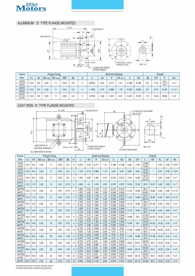
CAST IRON ‘D’ TYPE FLANGE MOUNTED
ALUMINIUM ‘D’ TYPE FLANGE MOUNTED
CABLE ENTRY KK
ØP
C±0.2
BB
'X'
AH
ES
ECCENTRICITY
'X'
BE
BC=0 ±1mm
ØB
D
ØA
K
(R
AB
BET)
FLANGE FACE RUNOUT
& SHAFT RUNOUT
AB
45
0
'N' HOLES DRILL Ø 'BF' AS
SHOWN ON 'AJ' PCD.
SECT. X-X
U
S
RG
D
ALL DIMENSONS IN INCHES
EARTHING TERMINALS
CABLE ENTRY KK
BE
BC=0+/-1mm
AH
FLANGE FACE RUNOUT
& SHAFT RUNOUT
C+/-0.25
BB
X
ECCENTRICITY
ES
X
AB
45
0
EYE BOLT WHEN REQD.
fC
fA
K(R
AB
BE
T)
fB
D
XL
AF
HB
'N' HOLS 'BF' AS SHOWN
ON 'AJ' PCD
f
S
GD
R
f U
SECT.-XX
MEPActotors
All dimensions are in inches. Please call forcertified drawing for engineering purpose.
Frame
Flange Fixing Shaft and Keyway Overall
Size
AJ
AK
BB max BD max ØBF
BE N
U
AH R
ES min S G
D AB
Ø
P KK
C
143TD
10.0 9.0 0.25 11 0.53 0.5 4 0.8750 2.25 0.771 1.41 0.188 0.188 5.5 7.10
12.4
1×1”
145TD 13.4
182TD
10.0 9.0 0.25 11 0.53 0.5 4 1.1250 2.75 0.986 1.78 0.250 0.250 6.5 8.75 15.35 1×1.5”
184TD
213TD
10.0 9.0 0.25 11 0.53 0.5 4 1.3750 3.38 1.201 2.41 0.312 0.312 7.3 10.24 18.94
1×2”
215TD

CA
ST
IR
ON
,'JM
/JP
'T
YP
EF
OO
TC
UM
FA
CE
MO
UN
TE
D
fU
SE
CT.-X
X
R
S
1-TA
PD
RILL
1/2-13X
1.5
DE
EP
4-H
OLE
S'B
F'
AS
SH
OW
NO
N'A
J'P
CD
f
AB
EC
CE
NT
RIC
IT
Y
H
G
AF
XL
HD
fH
2E
+/-0.3
A
f BD
f AK
FLA
NG
ER
UN
OU
T
&S
HA
FT
RU
NO
UT
CA
BLE
EN
TR
Y'K
K'
AH
X
ES
BB
BA
XF
2F
+/-0.3
B
EA
RT
HIN
GT
ER
MIN
ALS
OF
M8
SIZ
E
ER
X
ET
EQ
BC
=0+
/-1
mm
C+
/-0.25
f P
f EM
f EP
f EL
J
+0.05
-0.0
TO
LE
RA
NC
ES
Fram
eE
ccen
tricity
of
Flan
ge
Face
Sh
aft
Size
Mo
un
tin
gR
abb
et
Ru
no
ut
Ru
no
ut
25
4-2
56
0.0
04
”0
.0
04
”0
.0
02
”
Dim
en
sio
n
AJ
AK
BB
max.
U
To
leran
ce
Cen
trelin
e
ofø
BF
ho
les
+0
.0
00
”/
+0
.0
0”/
+0
.0
00
”/
with
in
±0
.0
25
”
–0
.0
05
”–0
.0
6”
–0
.0
01
”
Dim
en
sio
n‘S
’O
nS
haft
R
On
Key
Wid
th
(s)/
Key
Heig
ht(G
D)
To
leran
ce
+0
.0
03
”/
+0
.0
00
”/
+0
.0
00
”/–0
.0
03
”
–0
.0
00
”–0
.0
05
”
R
+0
.0
00
”/
–0
.0
15
”
28
4-3
26
0.0
06
”0
.0
06
”0
.0
03
”
14
3JM
4.5
00
0.1
56
1.1
56
1.0
00
00
.8
74
54
.2
81
0.7
71
0.1
88
0.6
40
2.8
90
15
.2
14
5JM
4.4
97
0.1
25
1.1
54
0.9
99
50
.8
74
04
.2
19
0.7
56
0.1
90
0.6
10
2.8
60
Flan
ge
Fixin
g
Sh
aft
an
dK
eyw
ay
Overall
AJ
AK
BB
max
BD
max
øB
F
EL
EM
UA
HR
ES
min
SE
Pm
in
EQ
ER
ET
AB
øP
CH
DX
LA
FK
K
25
4JM
7.2
50
8.5
00
0.3
12
10
1/2
-1
3
1.7
50
1.3
75
01
.2
49
55
.2
81
1.1
12
2.5
3
0.2
52
1.7
50
0.6
40
5.2
5
3.0
15
10
.4
81
2.5
22
6.5
41
4.8
6.4
92
.8
3
1
25
6JM
8.4
97
0.2
50
1.7
48
1.3
74
51
.2
49
05
.2
19
1.0
97
0.2
50
0.6
10
2.9
85
25
4JP
7.2
50
8.5
00
0.3
12
10
1/2
-1
3
1.7
50
1.3
75
01
.2
49
58
.1
56
1.1
12
2.5
3
0.2
52
1.7
50
2.3
90
8.1
25
5.8
90
10
.4
81
2.5
22
9.4
11
4.8
6.4
92
.8
3
1
25
6JP
8.4
97
0.2
50
1.7
48
1.3
74
51
.2
49
08
.0
94
1.0
97
0.2
50
2.3
60
5.8
60
28
4JM
11
.0
0
12
.5
00
.3
12
14
5/8
-1
1
1.7
50
1.3
75
01
.2
49
55
.2
81
1.1
12
2.5
3
0.2
52
2.1
25
0.6
40
5.2
5
3.0
20
11
.2
51
3.8
62
9.0
91
6.5
6.4
92
.8
31
.5
28
6JM
12
.4
95
0.2
50
1.7
48
1.3
74
51
.2
49
05
.2
19
1.0
97
0.2
50
0.6
10
2.9
80
28
4JP
11
.0
0
12
.5
00
.3
12
14
5/8
-1
1
1.7
50
1.3
75
01
.2
49
58
.1
56
1.1
12
2.5
3
0.2
52
2.1
25
2.3
90
8.1
25
5.8
95
11
.2
51
3.8
63
1.9
61
6.5
6.4
92
.8
31
.5
28
6JP
12
.4
95
0.2
50
1.7
48
1.3
74
51
.2
49
08
.0
94
1.0
97
0.2
50
2.3
60
5.8
55
32
4JM
11
.0
0
12
.5
00
.3
12
14
5/8
-1
1
1.7
50
1.3
75
01
.2
49
55
.2
81
1.1
12
2.5
3
0.2
52
2.1
25
0.6
45
5.2
5
3.0
20
13
.1
91
6.8
53
2.6
41
8.9
6.4
92
.8
3
2
32
6JM
12
.4
95
0.2
50
1.7
48
1.3
74
51
.2
49
05
.2
19
1.0
97
0.2
50
0.6
05
2.9
80
32
4JP
11
.0
0
12
.5
00
.3
12
14
5/8
-1
1
1.7
50
1.3
75
01
.2
49
58
.1
56
1.1
12
2.5
3
0.2
52
2.1
25
2.3
95
8.1
25
5.8
95
13
.1
91
6.8
53
5.5
11
8.9
6.4
92
.8
3
2
32
6JP
12
.4
95
0.2
50
1.7
48
1.3
74
51
.2
49
08
.0
94
1.0
97
0.2
50
2.3
55
5.8
55
4.0
5.0
00
5.8
75
6.6
2
3/8
-1
6
1.6
51
.1
56
4.2
55
.9
7.5
-
5.0
2.5
3/4
2.7
5
5.5
6.6
14
3.5
01
.3
77
0.5
11
-
4.0
5.0
5.9
84
16
.1
5
BA
XF
2F
2E
AB
HJ
G
14
3JP
5.8
75
4.5
00
0.1
56
6.6
2
3/8
-1
6
1.1
56
1.0
00
00
.8
74
57
.3
43
0.7
71
1.6
5
0.1
88
1.1
56
1.5
78
7.3
12
5.9
52
5.9
7.5
18
.2
6
-
5.0
2.5
3/4
14
5JP
4.4
97
0.1
25
1.1
54
0.9
99
50
.8
74
07
.2
81
0.7
56
0.1
90
1.5
48
5.9
22
2.7
5
4.0
5.5
6.6
14
5.0
00
3.5
01
.3
77
0.5
11
-
4.0
5.0
5.9
84
19
.2
3
18
2JM
5.8
75
4.5
00
0.1
56
6.6
2
3/8
-1
6
1.2
50
1.0
00
00
.8
74
54
.2
81
0.7
71
1.6
5
0.1
88
1.2
50
0.6
40
4.2
5
2.8
90
6.7
8.7
5
18
.6
8
10
.8
25
.0
2.5
3/4
18
4JM
4.4
97
0.1
25
1.2
48
0.9
99
50
.8
74
04
.2
19
0.7
56
0.1
90
0.6
10
2.8
60
3.5
0
4.5
7.5
8.7
46
.6
92
4.5
0
1.4
17
0.5
11
-
4.5
5.5
18
.6
2
18
2JP
5.8
75
4.5
00
0.1
56
6.6
2
3/8
-1
6
1.2
50
1.0
00
00
.8
74
57
.3
43
0.7
71
1.6
5
0.1
88
1.2
50
1.5
78
7.3
12
5.9
52
6.7
8.7
5
21
.7
4
10
.8
25
.0
2.5
3/4
18
4JP
4.4
97
0.1
25
1.2
48
0.9
99
50
.8
74
07
.2
81
0.7
56
0.1
90
1.5
48
5.9
22
3.5
0
4.5
7.5
8.7
46
.6
92
4.5
0
1.4
17
0.5
11
-
4.5
5.5
21
.6
8
21
3JM
7.2
5
8.5
00
0.3
12
9.0
1/2
-1
3
1.2
50
1.0
00
00
.8
74
54
.2
81
0.7
71
1.6
5
0.1
88
1.7
50
0.6
40
4.2
5
2.8
90
7.5
10
.6
20
.1
5
12
.5
95
.0
2.5
1
21
5JM
8.4
97
0.2
50
1.2
48
0.9
99
50
.8
74
04
.2
19
0.7
56
0.1
90
0.6
10
2.8
60
4.2
5
5.5
8.5
10
.0
7.0
00
5.2
51
.8
89
0.6
29
-
5.5
7.0
8.5
0
21
.8
8
21
3JP
7.2
5
8.5
00
0.3
12
9.0
1/2
-1
3
1.7
50
1.3
75
01
.2
49
58
.1
56
1.1
12
2.5
3
0.2
52
1.7
50
2.3
90
8.1
25
5.8
90
7.5
10
.6
24
.2
8
12
.5
95
.0
2.5
1
21
5JP
8.4
97
0.2
50
1.7
48
1.3
74
51
.2
49
08
.0
94
1.0
97
0.2
50
2.3
60
5.8
60
4.2
5
5.5
8.5
10
.0
7.0
0
5.2
51
.8
89
0.6
29
-
5.5
7.0
8.5
0
25
.7
6
4.7
5
8.2
5
10
.0
12
.1
25
11
.7
56
.2
52
.8
70
.8
75
-
8.2
5
10
.0
4.7
5
8.2
5
10
.0
12
.1
25
11
.7
56
.2
52
.8
70
.8
75
-
8.2
5
10
.0
4.7
5
9.5
11
.0
13
.7
01
2.7
57
.0
03
.3
00
.8
75
-
9.5
11
.0
4.7
5
9.5
11
.0
13
.7
01
2.7
57
.0
03
.3
00
.8
75
-
9.5
11
.0
5.2
5
10
.5
12
.5
15
.0
14
.0
8.0
02
.6
1.0
-
10
.5
12
.0
5.2
5
10
.5
12
.5
15
.0
14
.0
8.0
02
.6
1.0
-
10
.5
12
.0
Fo
ot
Fixin
g
FR
AM
E
SIZ
E
All dim
ensions are in inches.Please call for
certified drawing for engineering purpose.

The Oil Well Pump Motors are newly designed with superior
electrical performance & features.
The motors are designed with high slip and high torque
characteristics as per NEMA - D that is demanded by Oil well
beam pumping unit. The features as listed below coupled with
low initial cost and low maintenance cost make these motors
the obvious choice in the industry.
Locked
HP Frame FL FL Amps @ LR FLT LRT BDT Efficiency % Power Factor
Rotor
Speed KVA
SF Time Weight
Hot/
RPM 230V 460V 575V 796V Code Lb.Ft % FLT % FLT FL 0.75 FL 0.5 FL FL 0.75 FL 0.5 FL Cold (s) Lb
3 215T 1100 9.3 4.7 4 3 K 14.1 320 300 79 79 78 0.75 0.70 0.58 1.15 20/56 150
5 215T 1115 15 7.5 6 4.3 J 23.4 320 300 82 82 81 0.76 0.70 0.6 1.15 25/55 174
7.5 254T 1135 20 10 8 5.8 H 34.1 300 320 86.5 86 84 0.8 0.76 0.66 1.15 14/31 266
10 256T 1135 27 13.5 11 7.8 H 46.5 300 320 87 87 85 0.8 0.76 0.66 1.15 19/42 315
15 284T 1130 40 20 16 11 G 68.5 300 320 87.1 87 85 0.8 0.76 0.66 1.15 20/56 462
20 286T 1130 54 27 22 16 G 93.5 300 320 87.5 87 85 0.8 0.76 0.66 1.15 20/56 462
25 324T 1135 65 33 26 19 G 114.8 320 340 89 89 87 0.8 0.76 0.68 1.15 20/56 620
30 326T 1135 78 39 31 22 G 136.5 320 340 89 88 87 0.8 0.76 0.68 1.15 19/42 620
40 364/5T 1130 101 51 41 29 G 186.9 300 320 89.5 89.5 88.5 0.83 0.8 0.71 1.15 34/75 825
50 404/5T 1135 122 61 49 35 G 229.5 300 320 89.5 89.5 88.5 0.85 0.81 0.74 1.15 18/40 1100
60 404/5T 1140 147 74 59 43 G 277.9 300 320 90.2 90.2 89.5 0.85 0.81 0.74 1.15 28/62 1345
75 444/5T 1130 183 91 73 53 F 342.7 300 320 89 88 87 0.85 0.81 0.74 1.15 30/66 1544
100 444/5T 1125 249 124 100 72 G 469.4 300 320 89 88 87 0.85 0.81 0.74 1 30/66 1980
125 445T 1130 305 153 122 88 G 579.5 300 320 90 91 88 0.85 0.81 0.74 1 30/66 2200
150 447T 1140 353 177 141 102 G 679.4 300 320 92 92 89 0.85 0.81 0.74 1 30/66 2300
l
l
l
l
l
l
l
l
l
l
l
l
l
l
Cast-Iron Frame, End Brackets and Oversized Conduit
Box
IP55 TEFC, V-ring slinger on shaft
Double sealed bearings up to 215 frame, regreasable
bearings for 254 frame and above
Class F insulation
Service factor 1.15
104 F (40 C) ambient temperature
Altitude 3300ft (1000m)
1045 carbon steel shaft
Oversized Bearings selected for Belt-drive application
Stainless steel nameplate
NPT threaded Terminal box
Grounding Terminals on Frames and Inside Conduit Box
Stainless Steel Nameplate
Paint Synthetic Enamel on Alkyd High build primer
suitable for 200 hours salt spray life tested in accordance
with ASTM B117. Colour - WHITE
0 0
PREMIUM FEATURES
TOTALLY ENCLOSED FAN COOLED
HIGH TORQUE, NEMA DESIGN D, 5-8% SLIP
5 THROUGH 150HP, HORIZONTAL, F-2 MOUNTING
SINGLE VOLTAGE OR TRIPLE VOLTAGE 3 PHASE,
230-460-796 OR 575V, 60HZ
l
l
l
l
l
l
From 90 watts to 2.25 kW.
BS / NEMA Frames in Series 40 and 50 and Metric
Frames.
DP, TEFC and TE (AOM) enclosures.
General Purpose and Customer Specific applications.
For 120 or 240 Volts, 50 / 60 Hz supply suitability.
BS / NEMA motors with c-CSA-us mark for USA and
Canada, CE mark for Europe.
Single / Three Phase FHP Motors (FHP)
PERFORMANCE DATA
OIL WELL PUMP MOTORS
FRAME 215 TO 447T

POWER TECH INDUSTRIES INC.
PO BOX 24
OLATHE, KANSAS 66051
USAElectric MotorsPOWER TECHPOWER TECHPOWER TECH
Electric MotorsElectric Motors