Embed Size (px)
Citation preview

American-Eurasian Journal of Scientific Research 12 (5): 271-284, 2017ISSN 1818-6785© IDOSI Publications, 2017DOI: 10.5829/idosi.aejsr.2017.271.284
Corresponding Author: A. Nabisha, Assistant Professor, Loyola Institute of Technology and Science, Thovalai,Anna University Chennai, India.
271
Power Quality Enriched Wind Energy System usingDSTATCOM based on PID-ANN Controller
A. Nabisha and X. Felix Joseph1 2
Assistant Professor, Loyola Institute of Technology and Science,1
Thovalai, Anna University Chennai, IndiaAssociate Professor, Electrical and Electronics Engineering,2
Noorul Islam Centre for Higher Education, Kumaracoil, PRIST University Thanjavur, India
Abstract: Renewable energy source is adopted for the electric power generation, because of its valuable need.Among them wind based generation is one of the motivated sources for power production. In wind basedpower generation the wind turbines are used for generation purpose. Mostly the wind energy system is directlyintegrated with the power system for power supply. In case of direct integration, there arises a complexity formaintaining power quality. The power quality factors like voltage sag, voltage sag, swells, flickers, harmonicsetc. In order to maintain the power quality in power system while the usage of wind energy system, an externalcircuit is adopted. In this paper, we presents a novel approach to enrich the power quality in wind energysystem by using Proportional Integral Derivative (PID)-Artificial Neural Network (ANN) based DistributionStatic Compensator (DSTATCOM).Battery Energy Storage is integrated with DSTATCOM to withstand thepower at grid under fluctuating wind power. In our proposed method, ANN is used for tuning the parametersof PID controller. The power quality improvement for the grid connected wind energy system by using PID-ANN based DSTATCOM is implemented in MATLAB working platform and their experimental results arecompared with existing controllers like PI and PID controllers.
Key words: Wind Energy System Distribution Static Compensator (DSTATCOM) Proportional IntegralDerivative (PID) Controller Artificial Neural Network (ANN) Power Quality
INTRODUCTION integrated into the power system for power system usage
Today’s technological word completely depends on system presents a technical challenges and that requireselectricity; however the availability of electric source is consideration of voltage regulation, stability, powerlow. The deficiency of electricity becomes the breaking quality problems [7].point for developing countries like India. Hence the The power quality is an essential customer focusedresearch organizations tend into research to find a measure and is greatly affected by the operation of asuitable solution for providing uninterruptable electricity. distribution and transmission network. The issue of powerIn this situation the usage of renewable energy sources quality is of great importance to the wind turbine [8, 9].are the better solution, so these renewable energy sources During the normal operation, wind turbine produces aare encouraged for electricity production [1, 2]. In India continuous variable output power. These powermost available renewable source is wind and solar. The variations are mainly caused by the effect of turbulence,researches on these to area are under progressing [3, 4]. wind shear and tower-shadow and of control system inThe wind based energy acquisition is most encouraging the power system [10]. Thus, the network needs toresearch area because of its low complexity in installation manage for such fluctuations. The power quality issuesand maintain. In wind energy acquisition the wind turbine can be viewed with respect to the wind generation,is used [5]. The wind energy systems are directly transmission and distribution network, such as voltage
[6]. The integration of wind energy into existing power

Am-Euras. J. Sci. Res., 12 (5): 271-284, 2017
272
sag, swells, flickers, harmonics etc. [11]. However the due to increased renewable energy generation, frequencywind generator introduces disturbances into the deviations and power fluctuations of greater concern aredistribution network. One of the simple methods of being introduced to the grid, particularly in regions thatrunning a wind generating system is to use the induction are weakly interconnected with their surrounding areas,generator connected directly to the grid system [12].The such as small islands. Angel Molina-García et al. [21]induction generator has inherent advantages of cost have proposed a system for frequency control in isolatedeffectiveness and robustness. However induction power systems with relevant inclusion of wind powergenerators require reactive power for magnetization [13]. generation. They have analyzed the contribution of theWhen the generated active power of an induction demand side to the primary frequency control togethergenerator is varied due to wind, absorbed reactive power with an auxiliary frequency control, which was carried outand terminal voltage of an induction generator can be by variable-speed wind turbines through an additionalsignificantly affected [14]. control loop that synthesizes virtual inertia. Both the
A proper control scheme in wind energy generation suitability of these two additional control actionssystem is required under normal operating condition to counteracting frequency deviation and their potentialallow the proper control over the active power production reserves and compatibility was evaluated. The results[15]. In the event of increasing grid disturbance, a battery indicated a substantial improvement in both the dynamicenergy storage system for wind energy generating system performance and grid frequency stability.is generally required to compensate the fluctuation Mahmoud M. Amin et al. [22] have presented angenerated by wind turbine [16]. A Distribution Static improvement technique for the power quality of theCompensator (DSTATCOM) based control technology electrical part of a wind generation system with a self-has been proposed and implemented at point of common excited induction generator (SEIG) which aims to optimizecoupling (PCC) for improving the power quality which can the utilization of wind power injected into weak grids. Thetechnically manages the power level associates with the advantage of the proposed system was its simplicity duecommercial wind turbines [17]. The DSTATCOM is shunt to fewer controlled switches which leads to less controlconnected at the bus where the wind turbine is connected complexity. It also provided full control of active andto the power network to provide voltage regulation and reactive power injected into the grid using a voltageimprove the short-term transient voltage stability [18]. The source inverter (VSI) as a dynamic volt ampere reactiveDSTATCOM output is varied according to the controlled (VAR) compensator. A voltage oriented control (VOC)strategy, so as to maintain the power quality norms in the scheme was presented in order to control the energy to begrid system. The current control strategy is included in injected into the grid. In an attempt to minimize thethe control scheme that defines the functional operation harmonics in the inverter current and voltage and to avoidof the DSTATCOM compensator in the power system poor power quality of the wind energy conversion system[19]. A single DSTATCOM using insulated gate bipolar (WECS), a filter was inserted between VOC VSI and thetransistor was proposed to have a reactive power support, grid.to the induction generator and to the nonlinear load in the Venkata Yaramasu et al. [23] have proposed a newgrid system [20]. medium voltage power converter topology using a diode
The organization of the paper is summarized as rectifier, three level boost (TLB) converter and neutral-follows. Section 2 gives some of the recent research works point-clamped (NPC) inverter for a high-power permanentheld in power quality improvement of wind energy magnet synchronous generator-based wind energysystem. The proposed methodology for the power quality conversion system. The generator-side TLB converterenrichment by PID-ANN based DSTATCOM is explained performed the maximum power point tracking andin section 3. The implementation of the proposed method balancing of dc-link capacitor voltages, while the grid-sideand the experimental result with comparison is given in NPC inverter regulates the net dc-bus voltage andsection 4 followed by conclusion in section 5. reactive power to the grid. A significant improvement in
Related Works inverter no longer controls the dc-link neutral pointSome of the Recent Research Work Related to the Wind voltage. A model predictive strategy was proposed toEnergy System: Maintaining a close balance between control the complete system where the discrete-timepower generation and demand is essential for sustaining models of the proposed power electronic converters arethe quality and reliability of a power system. Currently, used to predict the future behavior of control variables.
the grid power quality was accomplished as the NPC

Am-Euras. J. Sci. Res., 12 (5): 271-284, 2017
273
These predictions were evaluated using two independent source voltage has a desired value. The injected currentcost functions and the switching states which minimize will cancel out the reactive part and harmonic part of thethese cost functions were selected and applied to the load and induction generator current, thus it improves thegenerator and grid-side converters directly. power factor and the power quality. The shunt connected
Ahmed M. Kassem et al. [24] have investigated the DSTATCOM with battery energy storage is connectedapplication of the Takagi –Sugeno (TS) fuzzy approach with the interface of the induction generator and non-for voltage and frequency control of an isolated wind linear load at the point of common coupling (PCC) in theturbine (WT) system with variable-speed permanent grid system. The DSTATCOM compensator output ismagnet synchronous generator (PMSG) and a system for varied according to the controlled strategy, so as tostoring energy during wind speed and load variations. maintain the power quality norms in the grid system. TheInitially, the holistic model of the entire system was current control strategy is included in the control schemeachieved, including the PMSG, the uncontrolled rectifier, that defines the functional operation of the STATCOMthe buck converter and the storage system. The power compensator in the power system. A single DSTATCOMabsorbed by the connected loads was effectively using insulated gate bipolar transistor is proposed todelivered and supplied by the proposed WT and energy have a reactive power support, to the induction generatorstorage systems, subject to TS-fuzzy control. The and to the nonlinear load in the grid system. The controlperformance of the system was compared with the system scheme approach is based on injecting the currents intowithout storage system. the grid using PID-ANN. The architecture of the proposed
Wind power (WP) penetration in weak distribution method is shown in Figure 1.networks is associated with adverse impacts on voltagequality. The installation of an energy storage system Power Quality Issues and Its Standards(ESS) is a possible voltage quality remedy in such milieus. InternationalElectro Technical Commission Guidelines:Moataz Ammar et al. [25] have proposed a super International Standards are established by the group ofcapacitor ESS for alleviation of voltage flicker resulting technical committee-88 of International Electro-Technicalfrom WP integration. Their ESS control and management Commission (IEC), IEC standard 61400-21, defines thewere tailored to that purpose such that the ESS offsets the method for defining the power quality characteristics offlicker-producing fluctuations in the generated WP. The wind turbine [26]. The specified standard norms areproposed power sizing of the ESS was defined by the IEC 61400-21: Wind turbine generating system, part-estimated turbulence intensity and wind speed average at 21. Assessment and measurement of power qualitythe installation site. A 2 MW wind generator of the characteristic grid connected turbine.doubly fed induction generator type was employed as a IEC 61400-13: Wind turbine – Measuring proceduresource of WP and simulations were conducted on a in defining behavior of power.simplified test system, as well as a detailed 25 kV IEC 61400-3-7: Assessment of emission limits fordistribution network on which results were compared with fluctuating load IEC 61400-12: Performance of windacknowledged reactive power flicker mitigation turbine.approaches and verified by prototyping in a real-timesimulation platform. Variation of Voltage: The issue of variation of voltage
Proposed Methodology: The power quality in the wind variation of voltage is directly linked to variations of realbased energy system is one of the big challenges in the and reactive power. The variation of voltage classifiedrecent research. In this work we intend to develop a wind commonly areenergy system with improved power quality. We consider Voltage Saga DSTATCOM based wind energy system, in which a Voltage Swellnovel controlling technique will be developed. The Short Interruptionsproposed controlling technique is the combination of Long Duration Voltage Variationproportional-integral-derivative controller and artificialneural network (PID-ANN). The DSTATCOM based The voltage flicker problem defines dynamiccurrent control voltage source inverter injects the current variations in the network caused by varying loads or windinto the grid in such a way that the source current are turbines. Thus, the power fluctuation from wind turbineharmonic free and their phase-angle with respect to arises during nonstop operation. The amplitude of voltage
results from generator torque and wind velocity. The

Control ler(PID -ANN )
SourceW ind
T urbine
InductionG enerator
No n-linear Load
DSTATCO M
+
- Battery
Vdc
PCC
312wind windP AV=
Am-Euras. J. Sci. Res., 12 (5): 271-284, 2017
274
Fig. 1: Architecture of the Proposed Method
fluctuation depends on network impedance, grid strength, the safety aspect and balance between real and reactivephase angle and power factor of wind turbines. It is power [27].described as a fluctuation of voltage in a frequency of 10-35 Hz. The IEC 61400-4-15 postulates a flicker meter that Consequences of Issues: The voltage variation,can be used to measure directly. harmonics, flicker causes the malfunction of apparatus’s
Harmonics: Harmonicsarises due to operation of power speed drives, programmable logic controller, flickering ofelectronics converters. The harmonic voltage and current screen and light. It leads to tripping of protection devices,should be restricted to the acceptable level at the point of tripping of contractors, stoppage of sensitive equipment’swind turbine connection to network. To certify the like programmable logic control system, personalharmonic voltage within limit, each source of harmonic computer and may stop the operation and even cancurrent can allow only a limited influence, as per the IEC- damage of sensitive equipment’s. Thus it reduces the61400-36 guideline. The rapid switching provides a large power quality of the grid.decrease in lower order harmonic current compared to theline commutated converter, but the output current will Topology for Power Quality Improvementhave high frequency current and can be easily filter out. Modelling of Wind Energy Generating System: In this
Wind Turbine Location: The path of connecting the wind topology with pitch control turbine. In our proposedgenerating system into the power system highly affects method, we have used induction generator because of itsthe power quality. Thus the operation and its effect on simplicity. Some of the properties of induction generatorpower system depend on the structure of connecting it does not require separate field circuit, it acceptspower network. constant and variable loads and has natural protection
Self-Excitation of WTGS: The self-excitation of WTGS energy system is given bywith an asynchronous generator takes place afterdisconnection of WTGS with local load. The risk of self-excitation occurs especially when WTGS is equipped with (1)compensating capacitor. The capacitor connected toinduction generator offers reactive power compensation. where (kg/m ) is air density and A (m ) is area sweptHowever the voltage and frequency are calculated by out by turbine, V is wind speed in meter/sec. It isbalancing the system. The drawbacks of self-excitation are not likely to mine all kinetic energy of wind, hence it
namely microprocessor based control system, adjustable
setup, wind generators are based on constant speed
against short circuit. The obtainable power of wind
3 2
wind

LOAD
Source
Ls PCC
VSC
Cdc
AC Filter Capacitor C
L
AC Filter ReactorTo
Transformer
DC Bus
DC Bus Capacitor
Battery+_
Mech p windP C P=
2 312mech wind pP R V C= Π
Am-Euras. J. Sci. Res., 12 (5): 271-284, 2017
275
Fig. 2: Distribution Static Compensator (DSTATCOM) side of the converter which is the reactive power storage
mine a fraction of power in wind, known as power storage element should be charged by converter itself orcoefficient C of wind turbine, which is given in below by using battery. If the AC terminal voltage is same asp
equation that of VSC input voltage then no reactive power is
(2) greater than AC terminal voltage DSTATCOM activates
The power coefficient depends on operating power amount is proportional to the difference of twocondition and type of wind turbine. This coefficient can voltages, but the voltage regulation at PCC and correctionbe defined as a function of pitch angle and tip speed of power factor should not be attained instantaneously.ratio . The mechanical power formed by wind turbine is DSTATCOM utilized for regulation of voltage at PCCspecified in below equation compensation can be such that supply current should
factor the supply current should be in phase with voltage(3) supply. DSTATCOM supplies flexible voltage and
where R denotes the radius of the blade in meter. system applications such as fast voltage recovery,
Modelling of DSTATCOM: Distribution Static system losses etc. The single line diagram ofCompensator (DSTATCOM) is a voltage controlled DSTATCOM with battery energy storage (BES) is shownreactive power source which normally comprises of in Figure 3.
Voltage Source Converter (VSC) and DC linkedcapacitor linked in shunt which is capable to absorb orproduce reactive power [28]. It has some relatedcharacteristics to that Static Synchronous Compensator(STATCOM). In transmission system, STATCOM areutilized whereas in order to achieve dynamiccompensation DSTATCOM is utilized in distributionsystem. The schematic diagram of DTATCOM is shownin Figure 2.
The VSC has AC terminals which are connected toPCC (Point of Common Coupling) through theinductance. The DC capacitor is connected on the DC
element carries the ripple current of converter. This
dispersed to the system and when the output voltage is
in capacitive mode and vice versa. The supplied reactive
lead voltage supply. Similarly for correction of power
reactive power control which is applied in many power
enhancing voltage stability of the system, minimization of
Fig. 3: Single line diagram of BES-DSTATCOM
( ) /sh L S L th L thI I I I V V Z= − = − −
*Sh L shP V I=
0
1 ( )( ) ( ) ( )t
p di
de tu t K e t e t dt KK dt
= + +∫
Am-Euras. J. Sci. Res., 12 (5): 271-284, 2017
276
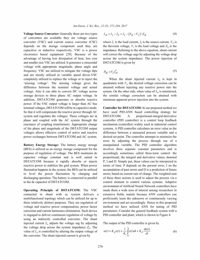
Voltage Source Converter: Generally there are two types (4)of converters are available they are voltage sourceconverter (VSC) and current source converter (CSC) where I is the load current, I is the source current, V isdepends on the storage component used they are the thevenin voltage, V is the load voltage and Z is thecapacitive or inductive respectively. VSC is a power impedance. Referring to the above equation, shunt currentelectronics based equipment [29]. Because of the will correct the voltage sags by adjusting the voltage dropadvantage of having less dissipation of heat, less cost across the system impedance. The power injection ofand smaller size VSC are utilized. It generates a sinusoidal DSTATCOM is given byvoltage with appropriate magnitude, phase angle andfrequency. VSC are utilized to mitigate the voltage dips (5)and are mostly utilized in variable speed drives.VSCcompletely utilized to replace the voltage or to inject the When the shunt injected current I is kept in‘missing voltage’. The missing voltage gives the quadrature with V , the desired voltage correction can bedifference between the nominal voltage and actual attained without injecting any reactive power into thevoltage. Also it can able to convert DC voltage across system. On the other side, when value of I is minimized,storage devices to three phase AC output voltage. In the similar voltage correction can be attained withaddition, DSTATCOM generates or absorbs reactive minimum apparent power injection into the system.power. If the VSC output voltage is larger than AC busterminal voltages, DSTATCOM will be in capacitive mode. Controller for DSTATCOM: In our proposed method weSo that it will compensate the reactive power through AC have used PID-ANN based controlling strategy forsystem and regulates the voltages. These voltages are in DSTATCOM. A proportional-integral-derivativephase and coupled with the AC system through the controller (PID controller) is a control loop feedbackreactance of coupling transformers. Appropriate change mechanism (controller) widely used in industrial controlof the phase and magnitude of the DSTATCOM output systems. A PID controller calculates an error value as thevoltages allows effective control of active and reactive difference between a measured process variable and apower exchanges between DSTATCOM and AC system. desired set point. The controller attempts to minimize the
Battery Energy Storage: The battery energy storage manipulated variable. The PID controller algorithm(BES) is utilized as an energy storage component for the involves three separate constant parameters and ispurpose of regulation of voltage. The BES maintains dc accordingly sometimes called three-term control: thecapacitor voltage constant and is well suited in proportional, the integral and derivative values, denotedDSTATCOM because it rapidly absorbs or injects P, I and D. Simply put, these values can be interpreted inreactive power to stabilize the grid system. When power terms of time: P depends on the present error, I on thefluctuation happens in the system, the BES can be utilized accumulation of past errors and D is a prediction of futureto level the power fluctuation by charging and errors, based on current rate of change. The weighted sumdischarging operation. The battery is connected in parallel of these three actions is used to adjust the process via ato the dc capacitor of DSTATCOM. control element to control various systems. Adaptive
Operating Principle of DSTATCOM: The VSC made them a wide area of interest among researchers inconnected in shunt with ac system delivers a extensive fields, mainly because ANN controllers canmultifunctional topology which can be utilized for up to proficiently learn the unknown or continuously varyingthree relatively distinct purposes. They are regulation of environment and act accordingly. Hence in this proposedvoltage and reactive power compensation, power factor method we have utilized ANN for tuning of PIDcorrection and current harmonics elimination. Such device parameters. Consider the general feedback system with ais engaged to deliver continuous regulation of voltage by PID controller and plant, which is shown in Figure 4.using an indirectly controlled converter. The shuntinjected current I adjusts the voltage sag by adjusting The output of the PID controller is given bysh
the voltage drop across the system impedance Z . Theth
value of I is controlled by altering the output voltage of (6)sh
the converter. The shunt injected current is given by
L S th
L th
Sh
L
Sh
error by adjusting the process through use of a
environment of Artificial Neural Network controllers have

PID-ANNController Plant
eReference Voltage Vref
Observed Voltage Vin
I1
I2
H 1
H 2
H 3
O
ref ine V V= −
11 12 13 1i i iW W W= = = +
21 22 23 1i i iW W W= = = −
1oO PW K=
2oO IW K=
3oO DW K=
1 11 1 21 2i i i
ref in ErrorH W I W I V V V= + = − =
2 12 1 22 2i i i
ref in ErrorH W I W I V V V= + = − =
3 13 1 23 2i i i
ref in ErrorH W I W I V V V= + = − =
1O
ErrorH V=
2
tO
Erroro
H V dt= ∫
3O ErrordVH
dt=
1 1 2 2 3 3
0
o O o O o OO O O
tError
P Error I Error D
u O W H W H W H
dVK V K V dt Kdt
= = + +
= + +∫
Am-Euras. J. Sci. Res., 12 (5): 271-284, 2017
277
Fig. 4: Block diagram of PID-ANN controller
Fig. 5: Structure of ANN
where u(t) is the controller output, K is the proportional (12)p
gain, K is the integral gain, K is the derivative time andI D
e(t) is the error between the reference voltage and the Now, the input of hidden layer nodes becomeobserved voltage which is given by
(7)
An artificial neural network tuned PID (PID-ANN)has two inputs, one outputs and three layers they are (15)input layer, hidden layer and output layer. The inputlayers has two neurons which are reference voltage V Similarly, the output of hidden layer nodes becomeref
and observed voltage V and the output layer has onein
which is controller output u(t). The hidden layers has (16)three neurons they are P-Neuron, I-Neuron and D-Neuronrespectively. The structure of ANN is shown in figure 5.
In ANN, by choosing appropriate connection (17)between neurons, an ANN becomes a conventional PIDcontroller. To achieve this, the weights between inputlayer and hidden layer are taken as (18)
(8)
(9)
(10)
(11) (19)
(13)
(14)
Then, the final output of neural network is given by

Step:1 Assign the weights for neuronsStep:2 Generate the neural network with two
inputs , three hidden layers
and one output layer.
Step:3 The final output of neural network is given by
where m indicates no. of hidden neurons, n represents no. of input, is the nth input
value and is the weight assignedbetween hidden layer and output layer,
is the weight assigned between inputlayer and hidden layer.
Step:4 Identification of learning error is given by
where is the learning error of theANN.
, ,1 2O OH H 3
OH
1
Z
error ii
BP e=
=∑
. .errorw BP∆ = ∂
3
1
13 n
nH
=∂ = ∑
312
11 exp
1
Hnm II Wn nm
n
= = + − =
∑∑
neww w w= + ∆
2
0 ErrorMSE V dt∞
= ∫
Am-Euras. J. Sci. Res., 12 (5): 271-284, 2017
278
Fig. 6: Steps Involved in ANN
where and are the output part of hiddenlayer nodes and O is the input part of the output layer.Based on this ANN is used for tuning of PID controllersin a varying environment.PID controllers have beenextensively used in control systems and there are muchmore experiences to choose K , K and K parameters inP I D
order to suit the stability. So, if a PID-ANN equals to aPID controller, it has the useful grounds of the use.Then, through training and study, PID-ANN can getbetter control performances. The main steps involved inartificial neural network is given below.
The error between the nodes is transmitted backtowards the hidden layer. This is called the backward passof the back propagation algorithm. Then the training isrepeated for some other training sets by changing theweights of the neural network. In the back propagationalgorithm, initially the weights are assigned to hiddenlayer neurons. The input layer has a constant weight,whereas the weights for output layer neurons are chosenrandomly. Then, the final output of neural network iscalculated. Next, we need to calculate the backpropagation error which is given by
(20)
where, BP is the back propagation error, the weighterror
deviation in the hidden neuron is calculated by using
(21)
where, is the weight deviation, is the learning rate,w
which usually ranges from 0.2 to 0.5, is the average ofhidden neurons output.
(22)
where,
H is the n output at hidden neuron or activationnth
function at input side. Then the new weights can becalculated by using
(23)
where, w the new weight and w is the current weight.new
Then process is repeated until the BP error gets minimizedor the value of mean square error (MSE) is minimum whichis given by
(24)
The training of the neural network has been done byvarying the PID parameters and taking the sample online.
RESULTS AND DISCUSSIONS
The proposed system for the power quality control inwind energy system using DSTATCOM based on PID-ANN controller is implemented in the working platform ofMatlab/Simulink. The system parameter for the proposedmethod is given Table 1.
The performance of the proposed method forstabilization of wind energy system is analyzed based onthree conditions they are normal condition, sag conditionand swell condition. In normal, the voltage required andthe generated are same hence there is no need ofcompensation in this case the DSTATCOM will not be
Am-Euras. J. Sci. Res., 12 (5): 271-284, 2017
279
Table 1: System Parameters
S. No Parameters Specifications
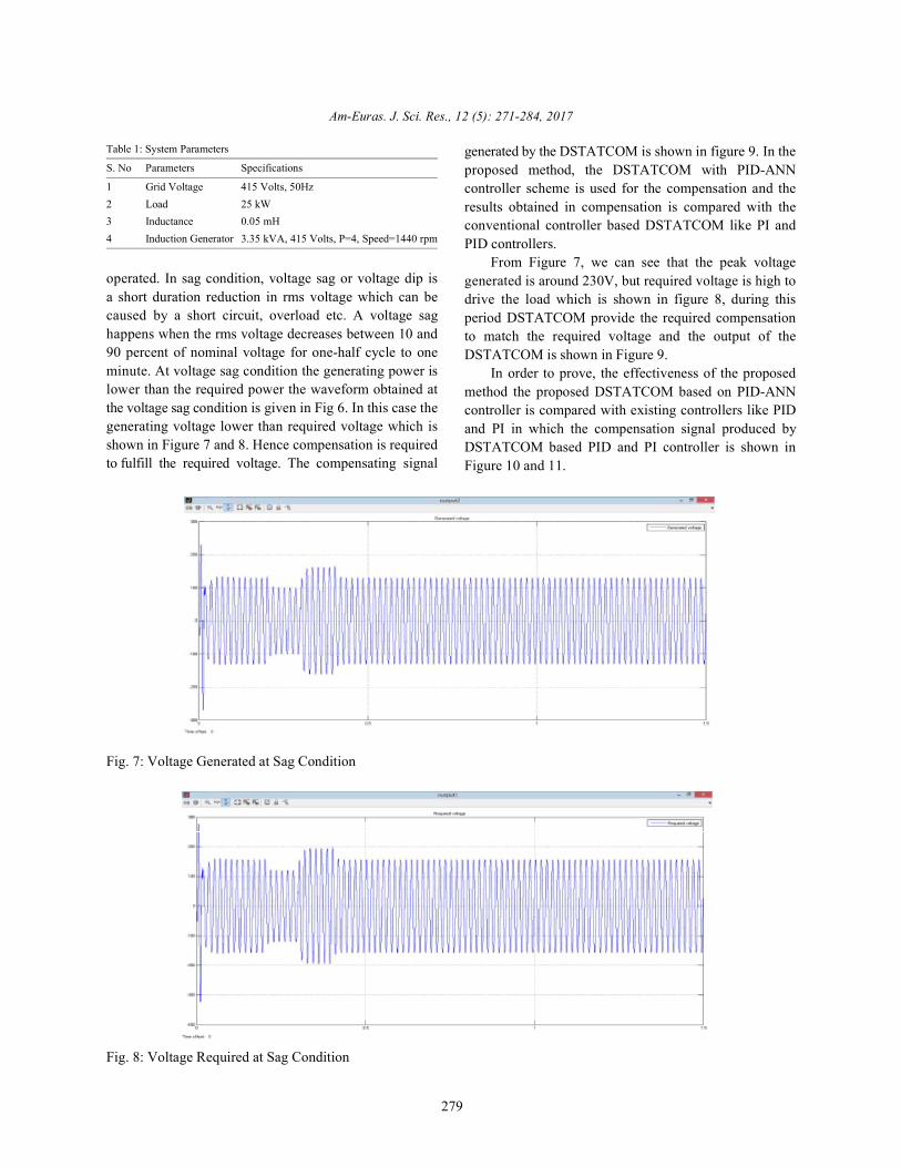
1 Grid Voltage 415 Volts, 50Hz2 Load 25 kW3 Inductance 0.05 mH4 Induction Generator 3.35 kVA, 415 Volts, P=4, Speed=1440 rpm
operated. In sag condition, voltage sag or voltage dip isa short duration reduction in rms voltage which can becaused by a short circuit, overload etc. A voltage saghappens when the rms voltage decreases between 10 and90 percent of nominal voltage for one-half cycle to oneminute. At voltage sag condition the generating power islower than the required power the waveform obtained atthe voltage sag condition is given in Fig 6. In this case thegenerating voltage lower than required voltage which isshown in Figure 7 and 8. Hence compensation is requiredto fulfill the required voltage. The compensating signal
generated by the DSTATCOM is shown in figure 9. In theproposed method, the DSTATCOM with PID-ANNcontroller scheme is used for the compensation and theresults obtained in compensation is compared with theconventional controller based DSTATCOM like PI andPID controllers.
From Figure 7, we can see that the peak voltagegenerated is around 230V, but required voltage is high todrive the load which is shown in figure 8, during thisperiod DSTATCOM provide the required compensationto match the required voltage and the output of theDSTATCOM is shown in Figure 9.
In order to prove, the effectiveness of the proposedmethod the proposed DSTATCOM based on PID-ANNcontroller is compared with existing controllers like PIDand PI in which the compensation signal produced byDSTATCOM based PID and PI controller is shown inFigure 10 and 11.
Fig. 7: Voltage Generated at Sag Condition
Fig. 8: Voltage Required at Sag Condition

Am-Euras. J. Sci. Res., 12 (5): 271-284, 2017
280
Fig. 9: Output of proposed DSTATCOM based on PID-ANN at Voltage Sag Condition
Fig. 10: Output of DSTATCOM based on PID at Voltage Sag Condition
Fig. 11: Output of DSTATCOM based on PI at Voltage Sag Condition

Am-Euras. J. Sci. Res., 12 (5): 271-284, 2017
281
Fig. 12: Generated Voltage at Swell Condition
Fig. 13: Required Voltage at Swell Condition
Fig. 14: Output of proposed DSTATCOM based on PID-ANN at Swell condition

Am-Euras. J. Sci. Res., 12 (5): 271-284, 2017
282
Fig.15: Output of DSTATCOM based on PID at swell condition
Fig. 16: Output of DSTATCOM based on PI at swell condition
Voltage swell is another kind of power quality by the proposed DSTATCOM based on PID-ANNproblem. Voltage swell is the opposite of voltage controller is shown in Figure 14.sag. Voltage swell, which is a momentary increase Similarly, the compensation signal produced by thein voltage, happens when a heavy load conventional DSTATCOM based PID and PI controller isturns off in a power system. The voltage shown in Figure 15 and 16.generated at swell condition is shown in Figure 12 From the performance analyses shown from figure 7and the required amount of voltage is shown in to figure 16,we can see that the performance of theFigure 13. proposed method shows that at different condition it can
From Figure 12, we can see that the generated operate well and provide effective compensation than themaximum peak voltage 310 Volts at swell, but the other conventional controller based DSTATCOM in windrequired voltage is lower this we can see in Figure 13, energy system. From the simulation results, we can sayat this period the DSTATCOM absorbs reactive that our proposed controller for DSTATCOM has highfrom the grid and it will match the generated and performance in terms of maintaining stability comparedrequired voltage. The compensating signal produced with other existing controllers like PI and PID controllers.

Am-Euras. J. Sci. Res., 12 (5): 271-284, 2017
283
CONCLUSION 7. Lopes, J.A., N. Hatziargyriou, J. Mutale, P. Djapic
This proposed method presents a novel PID-ANN generation into electric power systems: A review ofbased DSTATCOM for improvement of power quality in drivers, challenges and opportunities. Electric Powergrid connected wind generating system consists of Systems Research, 77(9): 1189-1203.nonlinear load. The proposed method has the capacity to 8. Vilar, C., H. Amarís and J. Usaola, 2006. Assessmentcancel out the harmonic components of the load. of flicker limits compliance for wind energyDSTATCOM with battery energy storage maintains the conversion system in the frequency domain.voltage source and provided the reactive power Renewable Energy, 31(8): 1089-1106.compensation for the wind generator and load at point of 9. Fan, J. and S. Borlase, 2009. The evolution ofcommon coupling in the grid system. The power quality distribution. IEEE Power and Energy Magazine,improvement for the grid connected wind energy system 7(2): 63-68.by using PID-ANN based DSTATCOM is implemented in 10. Mohod, S.W. and M.V. Aware, 2010. A STATCOM-MATLAB working platform and their experimental results control scheme for grid connected wind energyare compared with existing controllers like PI and PID system for power quality improvement. IEEE Systemscontrollers. Thus, the proposed method has high Journal, 4(3): 346-352.performance and reduces the power quality issues from 11. Arrillaga, J., M.H.J. Bollen and N.R. Watson, 2000.this we can say that proposed control scheme is best Power quality following deregulation. Proceedings ofmethod for grid connected wind generating system. the IEEE, 88(2): 246-261.
REFERENCES tracking the peak power points for a variable speed
1. Orlikowski, W.J. and J.J. Baroudi, Studying on Energy Conversion, 18(1): 163-168. information technology in organizations: Research 13. Simoes, M.G. and F.A. Farret, 2004. Renewableapproaches and assumptions. Information systems energy systems: design and analysis with inductionresearch, 1991; 2 (1): 1-28. generators. CRC press.
2. Dresselhaus, M.S., and I.L. Thomas, 2001. Alternative 14. Chen, Z., J.M. Guerrero and F. Blaabjerg, 2009. Aenergy technologies. Nature, 414(6861): 332-337. review of the state of the art of power electronics for
3. Jacobson, M.Z. and M.A. Delucchi, 2011. Providing wind turbines. IEEE Transactions on Powerall global energy with wind, water and solar power, Electronics, 24(8): 1859-1875.Part I: Technologies, energy resources, quantities 15. Tan, K. and S. Islam, 2004. Optimum controland areas of infrastructure and materials. Energy strategies in energy conversion of PMSG windPolicy, 39(3): 1154-1169. turbine system without mechanical sensors. IEEE
4. Vries, B.J.M.D., D.P.V. Vuuren and M.M. Hoogwijk, Transactions on Energy Conversion, 19(2): 392-399.2007. Renewable energy sources: Their global 16. Divya, K.C. and J. Ostergaard, 2009. Battery energypotential for the first-half of the 21st century at a storage technology for power systems-An overview.global level: An integrated approach. Energy policy, Electric Power Systems Research, 79(4): 511-520.35(4): 2590-2610. 17. Yuvaraj, V., E.P. Raj, A. Mowlidharan and
5. Lewis, J.I., 2007. Technology acquisition and L. Thirugnanamoorthy, 2011. Power qualityinnovation in the developing world: wind turbine improvement for grid connected wind energy systemdevelopment in China and India. Studies in using FACTS device. In Proceedings of IEEE Jointcomparative International Development, 3rd Int'l Workshop on Nonlinear Dynamics and42(3-4): 208-232. Synchronization & 16 International Symposium on
6. Carrasco, J.M., L.G. Franquelo, J.T. Bialasiewicz, Theoretical Electrical Engineering, pp: 1-7.E. Galván, R.C.P. Guisado, M.A.M. Prats and 18. Qiao, W., G.K. Venayagamoorthy and R.G. Harley,J.I. León, 2006. Moreno-Alfonso N. Power-electronic 2009. Real-time implementation of a STATCOM on asystems for the grid integration of renewable energy wind farm equipped with doubly fed inductionsources: A survey. IEEE Transactions on Industrial generators. IEEE Transactions on IndustryElectronics, 53(4): 1002-1016. Applications, 45(1): 98-107.
and N. Jenkins, 2007. Integrating distributed
12. Datta, R. and V.T. Ranganathan, 2003. A method of
wind energy conversion system. IEEE transactions
th

Am-Euras. J. Sci. Res., 12 (5): 271-284, 2017
284
19. Muthusamy, M. and C.S. Kumar, 2014. New 24. Kassem, A.M. and S.A. Zaid, 2014. Load parameterSTATCOM control scheme for power quality waveforms improvement of a standalone wind-basedimprovement in wind farm. In Proceedings of IEEE energy storage system and Takagi– Sugeno fuzzyInternational Conference on In Green Computing logic algorithm. IET Renewable Power Generation,Communication and Electrical Engineering, pp: 1-5. 8(7): 775-785.
20. Singh, B. and G.K. Kasal, 2008. Solid state voltage 25. Ammar, M. and G. Joos, 2014. A Short-Term Energyand frequency controller for a standalone wind power Storage System for Voltage Quality Improvement ingenerating system. IEEE Transactions on Power Distributed Wind Power. IEEE Transactions onElectronics, 23(3): 1170-1177. Energy Conversion, 29(4): 997-1007.
21. Molina-García, A., I. Muñoz-Benavente, A.D. Hansen 26. Tsili, M. and S. Papathanassiou, 2009. A review ofand E. Gómez-Lázaro, 2014. Demand-Side grid code technical requirements for wind farms. IETContribution to Primary Frequency Control With Renewable Power Generation, 3(3): 308-332.Wind Farm Auxiliary Control. IEEE Transactions on 27. Gutierrez, J.J., J. Ruiz, L.A. Leturiondo andPower Systems, 29(5): 2391-2399. A. Lazkano, 2008. Flicker measurement system for
22. Amin, M.M. and O.A. Mohammed, 2011. wind turbine certification. IEEE Transactions onDevelopment of High-Performance Grid-Connected Instrumentation and Measurement, 57(12): 375-382.Wind Energy Conversion System for Optimum 28. Vardhana, P.H., B.K. Kumar and M. Kumar, 2009. AUtilization of Variable Speed Wind Turbines. IEEE robust controller for DSTATCOM. In Proceedings ofTransactions on Sustainable Energy, 2(3): 235-245. IEEE International Conference on Power Engineering,
23. Yaramasu, V. and B. Wu, 2014. Predictive Control of Energy and Electrical Drives, pp: 546-551.a Three-Level Boost Converter and an NPC Inverter 29. Kim, J.H. and S.K. Sul, 2004. A carrier-based PWMfor High-Power PMSG-Based Medium Voltage Wind method for three-phase four-leg voltage sourceEnergy Conversion Systems. IEEE Transactions on converters. IEEE Transactions on Power Electronics,Power Electronics, 29(10): 5308-5313. 19(1): 66-75.


![REVIEW OF CONTROL STRATEGIES OF DSTATCOM · Fig. 2 Equivalent circuit of DSTATCOM The operation of DSTATCOM is explained in the following modes [2]: Mode 1: If V SHabc is in-phase](https://img.pdfslide.net/doc/110x75/5ec37ced6f2e09596744a3b6/review-of-control-strategies-of-dstatcom-fig-2-equivalent-circuit-of-dstatcom-the.jpg)