Embed Size (px)
Citation preview
International Journal of Electrical and Computer Engineering.
ISSN 0974-2190 Volume 8, Number 1 (2016), pp. 71-83
© International Research Publication House
http://www.irphouse.com
Power Quality Improvement & Energy Management
Using Mmc Based Active Device
M.Ramesh1
Assistant Professor1, A.I.T.S-Rajampet, A.P, INDIA.
R. Madhan Mohan2
Assistant Professor2, A.I.T.S-Rajampet, A.P, INDIA.
B. Ajeyudu3 PG Student3, A.I.T.S-Rajampet, A.P, INDIA.
Abstract
A transformer less hybrid series active filter is proposed to enhance the power
quality in single-phase systems with critical loads. This paper assists the
energy management and power quality issues related to electric transportation
and focuses on improving electric vehicle load connection to the grid. The
control strategy is de-signed to prevent current harmonic distortions of
nonlinear loads to flow into the utility and corrects the power factor of this
later. While protecting sensitive loads from voltage disturbances, sags, and
swells initiated by the power sys- tem, ridded of the series transformer, the
configuration is advantageous for an industrial implementation. This
polyvalent hybrid topology allowing the harmonic isolation and compensation
of voltage distortions could absorb or inject the auxiliary power to the grid.
Aside from practical analysis, this paper also investigates on the influence of
gains and delays in the real-time controller stability. The simulations results
are presented in this concept were carried out on a 2-kVA laboratory prototype
demonstrating the effectiveness of the proposed topology.
Keywords - Current harmonics, electric vehicle, hybrid series active filter
(HSAF), power quality, and real-time control.
72 M.Ramesh, R. Madhan Mohan and B. Ajeyudu
I. INTRODUCTION The figure of future Smart Grids connected with electric vehicle charging stations has
made a genuine worry on all parts of force nature of the force framework; while
boundless electric vehicle battery charging units [1], [2] affect power dispersion
framework consonant volt-age levels [3]. Then again, the development of sounds
sustained from nonlinear burdens like electric vehicle drive battery chargers [4], [5],
which surely impactsly affect the force framework and influence plant gear, ought to
be considered in the improvement of cutting edge matrices. In like manner, the
expanded rms and crest estimation of the twisted current waveforms build warming
and misfortunes and cause the disappointment of the electrical gear. Such wonder
adequately decreases framework proficiency and ought to have legitimately been
tended to [6], [7].
Additionally, to secure the purpose of regular coupling (PCC) from voltage
mutilations, utilizing a dynamic voltage restorer (DVR) capacity is prompted. An
answer is to lessen the contamination of force gadgets based loads straightforwardly
at their source. They were created to dispose of current sounds delivered by nonlinear
burden from the force framework. SeAFs are less scattered than the shunt sort of
dynamic channels [8], [9]. The upside of the SeAF contrasted with the shunt sort is
the second rate rating of the compensator versus the heap ostensible rating [10]. Be
that as it may, the multifaceted nature of the setup and need of a disengagement
arrangement transformer had decelerated their modern application in the dispersion
framework. The second classification was created in worry of tending to voltage
issues on touchy burdens. Normally known as DVR, they have a comparable setup as
the SeAF. These two classes are not quite the same as each other in their control rule.
This distinction depends on the reason for their application in the framework.
The benefit of the proposed arrangement is that non-straight Consonant voltage and
current creating burdens could be viably adjusted. The transformerless mixture
arrangement dynamic channel (THSeAF) is an option choice to routine force moving
converters in circulated era frameworks with high entrance of renewable vitality
sources, where every stage can be controlled independently and could be worked
freely of different stages. This paper demonstrates that the detachment of a three-stage
converter into single-stage H-span converters has permitted the end of the expensive
disengagement transformer and advances modern application for sifting purposes. The
setup has indicated extraordinary capacity to perform asked for remunerating errands
for the revision of current and voltage contortions, PF amendment, and voltage
reclamation on the heap terminal.
Power Quality Improvement & Energy Management Using Mmc Based Active Device 73
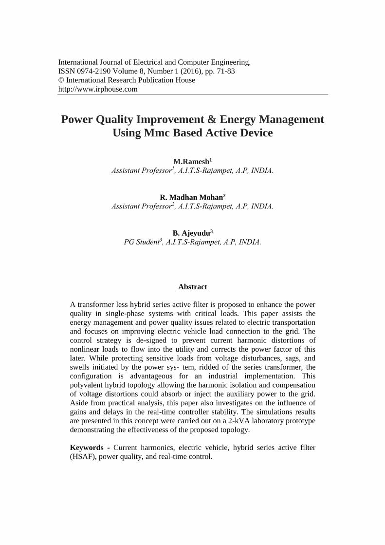
Fig.1: (a) Schematic of a single-phase smart load with the compensator installation
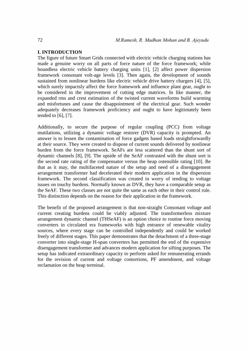
Fig.1: (b) Electrical diagram of the THSeAF in a single-phase utility.
This paper is sorted out as takes after. The framework design is presented in the
accompanying segment. At that point, the operation rule of the proposed design is
clarified. The third segment is committed to the demonstrating and investigation of
the control calculation executed in this work. The dc voltage direction and its
contemplations are quickly clarified, and the voltage and current symphonious
recognition strategy is expressly portrayed.
To assess the setup and the control approach, a few situations are reenacted. Test
results performed in the research facility are exhibited to approve recreations. This
paper is condensed with a conclusion and supplement where further scientific
improvements are illustrated.
74 M.Ramesh, R. Madhan Mohan and B. Ajeyudu
II. SYSTEM ARCHITECTURE
A. System Configuration The THSeAF appeared in Fig. 1 is made out of a H-span converter associated in
arrangement between the source and the heap. A shunt inactive capacitor guarantees a
low impedance way for current music. A dc assistant source could be associated with
infuse power amid voltage lists. The dc-join vitality stockpiling framework is depicted
in [19]. The framework is actualized for an appraised force of 2200 VA. To guarantee
a quick transient reaction with adequate dependability edges over an extensive variety
of operation, the controller is executed on a dSPACE/dsp1103.
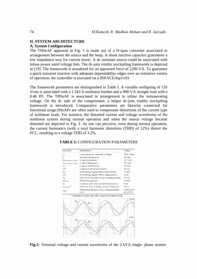
The framework parameters are distinguished in Table I. A variable wellspring of 120
Vrms is associated with a 1.1kVA nonlinear burden and a 998-VA straight load with a
0.46 PF. The THSeAF is associated in arrangement to infuse the remunerating
voltage. On the dc side of the compensator, a helper dc-join vitality stockpiling
framework is introduced. Comparative parameters are likewise connected for
functional usage.HSeAFs are often used to compensate distortions of the current type
of nonlinear loads. For instance, the distorted current and voltage waveforms of the
nonlinear system during normal operation and when the source voltage became
distorted are depicted in Fig. 2. As one can perceive, even during normal operation,
the current harmonics (with a total harmonic distortion (THD) of 12%) distort the
PCC, resulting in a voltage THD of 3.2%.
TABLE I: CONFIGURATION PARAMETERS
Fig.2: Terminal voltage and current waveforms of the 2-kVA single- phase system
Power Quality Improvement & Energy Management Using Mmc Based Active Device 75
without compensator. (a) Regular operation. (b) Grid’s voltage distortion (scales: 50
V/div for channel 1 and 10 A/div for channel 2).
The conduct of the framework when the matrix is profoundly contaminated with
19.2% of THD is likewise delineated. The proposed arrangement could be exclusively
associated with the lattice with no need of a massive and expensive arrangement
infusion transformer, making this topology equipped for remunerating source current
music and voltage twisting at the PCC. Regardless of the possibility that the quantity
of switches has expanded, the transformer less arrangement is more than whatever
other arrangement compensators, which for the most part uses a transformer to infuse
the remuneration voltage to the force framework. The enhanced uninvolved channel is
made out of fifth, seventh, and high-pass channels. The latent channel ought to be
balanced for the framework upon burden and government controls. An examination
between various existing arrangements is given in Table II. It is planned to bring up
the points of interest and disservices of the proposed arrangement over the customary
topologies.
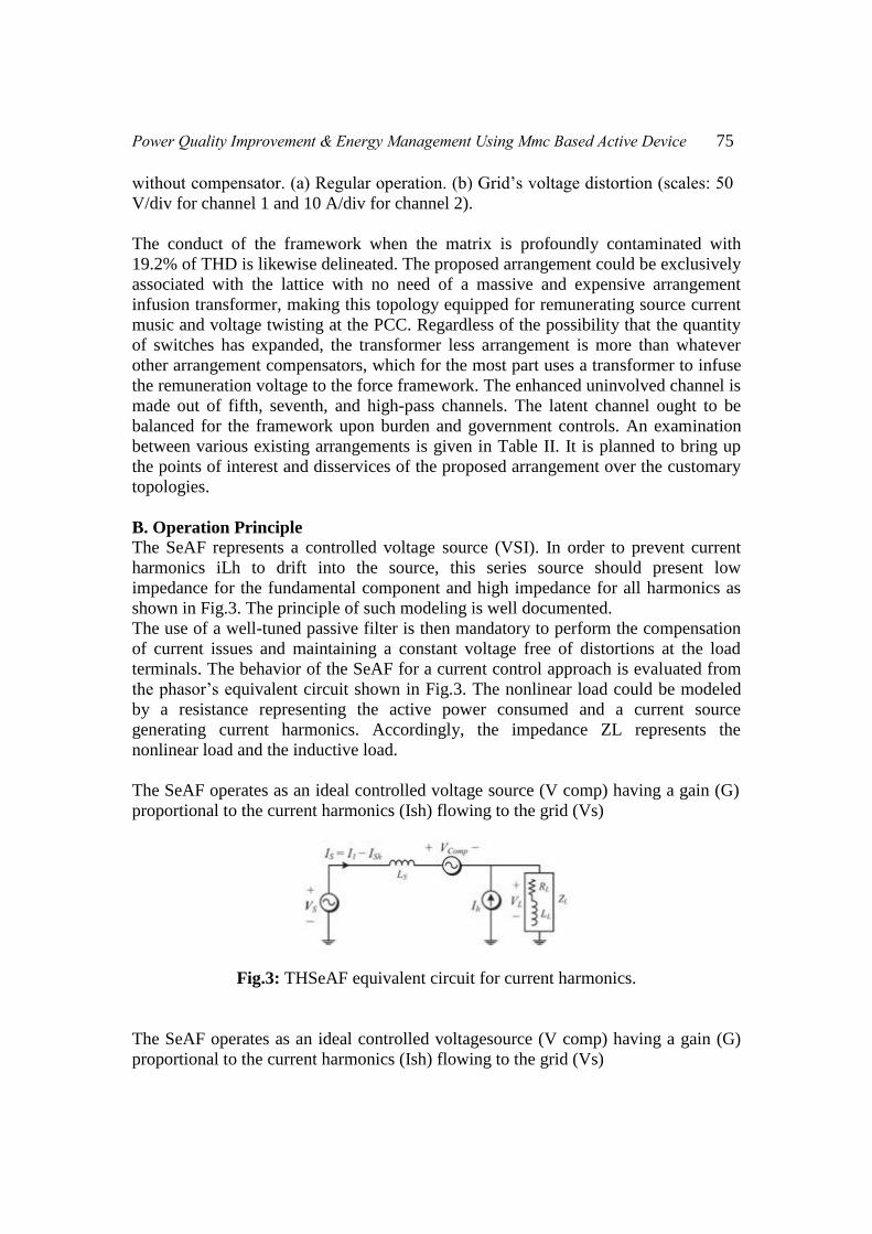
B. Operation Principle The SeAF represents a controlled voltage source (VSI). In order to prevent current
harmonics iLh to drift into the source, this series source should present low
impedance for the fundamental component and high impedance for all harmonics as
shown in Fig.3. The principle of such modeling is well documented.
The use of a well-tuned passive filter is then mandatory to perform the compensation
of current issues and maintaining a constant voltage free of distortions at the load
terminals. The behavior of the SeAF for a current control approach is evaluated from
the phasor’s equivalent circuit shown in Fig.3. The nonlinear load could be modeled
by a resistance representing the active power consumed and a current source
generating current harmonics. Accordingly, the impedance ZL represents the
nonlinear load and the inductive load.
The SeAF operates as an ideal controlled voltage source (V comp) having a gain (G)
proportional to the current harmonics (Ish) flowing to the grid (Vs)
Fig.3: THSeAF equivalent circuit for current harmonics.
The SeAF operates as an ideal controlled voltagesource (V comp) having a gain (G)
proportional to the current harmonics (Ish) flowing to the grid (Vs)
76 M.Ramesh, R. Madhan Mohan and B. Ajeyudu
Vcomp=G.Ish-VLh (1)
This allows having individual equivalent circuit for the fundamental and harmonics
Vsource = Vs1 +Vsh, VL = VL1 +VLh.
(2)
If gain G is sufficiently large (G → ∞), the source current will become clean of any
harmonics (Ish→ 0). This will help improve the voltage distortion at the grid side. In
this approach, the THSeAF behaves as high-impedance open circuit for current
harmonics, while the shunt high-pass filter tuned at the system frequency creates a
low-impedance path for all harmonics and open circuit for the fundamental; it also
helps for PF correction.
III. MODELING AND CONTROLOF THE SINGLE-PHASE THSeAF
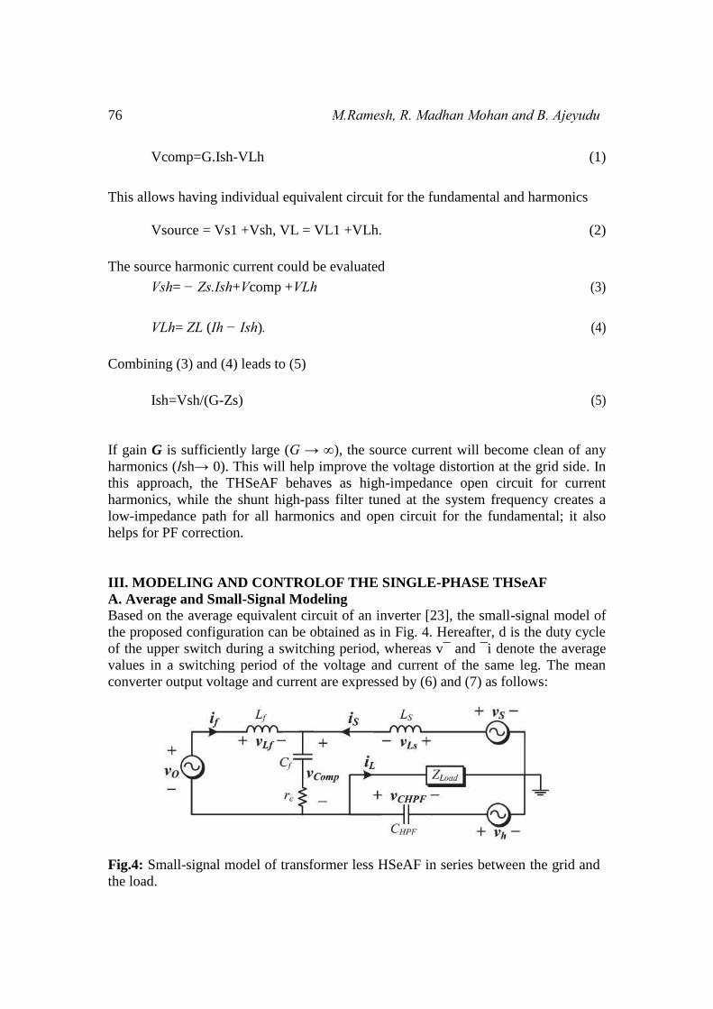
A. Average and Small-Signal Modeling Based on the average equivalent circuit of an inverter [23], the small-signal model of
the proposed configuration can be obtained as in Fig. 4. Hereafter, d is the duty cycle
of the upper switch during a switching period, whereas v¯ and ¯i denote the average
values in a switching period of the voltage and current of the same leg. The mean
converter output voltage and current are expressed by (6) and (7) as follows:
Fig.4: Small-signal model of transformer less HSeAF in series between the grid and
the load.
The source harmonic current could be evaluated
Vsh= − Zs.Ish+Vcomp +VLh (3)
VLh= ZL (Ih − Ish). (4)
Combining (3) and (4) leads to (5)
Ish=Vsh/(G-Zs) (5)
Power Quality Improvement & Energy Management Using Mmc Based Active Device 77
Vo=(2d-1)VDC (6)
where the (2d − 1) equals to m, then
IDC=mif (7)
Calculating the Thevenin equivalent circuit of the harmonic current source leads
to the following assumption:
Vh= -jIh/(CHPF.Wh) (8)
If the harmonic frequency is high enough, it is possible to assume that there will be no
voltage harmonics across the load. The state-space small-signal ac model could be
derived by a linearized perturbation of the averaged model as follows:
�̇� = 𝐴𝑥 + 𝐵𝑢 (9)
Moreover, the output vector is
𝑦 = 𝐴𝑥 + 𝐵𝑢 (10)
By means of (9) and (10), the state-space representation of the model is obtained as
shown in Fig. 4.
The transfer function of the compensating voltage versus the load voltage, TV_CL(s),
and the source current, TCI (s), are developed in the Appendix. Meanwhile, to control
the active part independently, the derived transfer function should be autonomous
from the grid configuration. The transfer function TVm presents the relation between
the output voltages of the converter versus the duty cycle of the first leg converter’s
upper switch
𝑇𝑣(𝑠) = 𝑉𝑐𝑜𝑚𝑝
𝑉𝑜=
𝑟𝑐𝐶𝑓𝑠+1
𝐿𝑓𝐶𝑓𝑠2+𝑟𝑐𝐶𝑓𝑠+1 (11)
𝑇𝑣𝑚(𝑠) =𝑉𝑐𝑜𝑚𝑝
𝑚= 𝑉𝐷𝐶 . 𝑇𝑉(𝑠) (12)
The further detailed derivation of steady-state transfer functions is described in
Section V.
A dc auxiliary source should be employed to maintain an adequate supply on the load
terminals. During the sag or swell conditions, it should absorb or inject power to keep
the voltage magnitude at the load terminals within a specified margin. Consequently,
the dc-link voltage across the capacitor should be regulated as demonstrated in Fig. 5.
78 M.Ramesh, R. Madhan Mohan and B. Ajeyudu
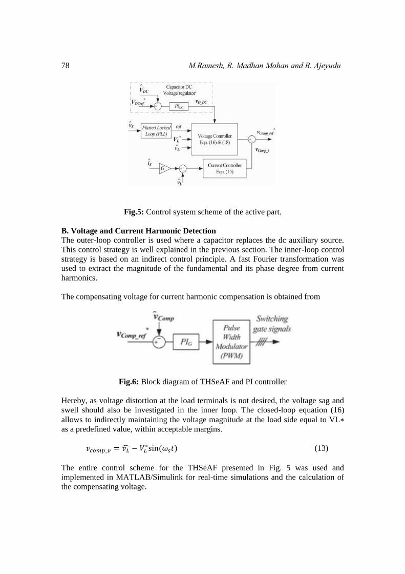
Fig.5: Control system scheme of the active part.
B. Voltage and Current Harmonic Detection The outer-loop controller is used where a capacitor replaces the dc auxiliary source.
This control strategy is well explained in the previous section. The inner-loop control
strategy is based on an indirect control principle. A fast Fourier transformation was
used to extract the magnitude of the fundamental and its phase degree from current
harmonics.
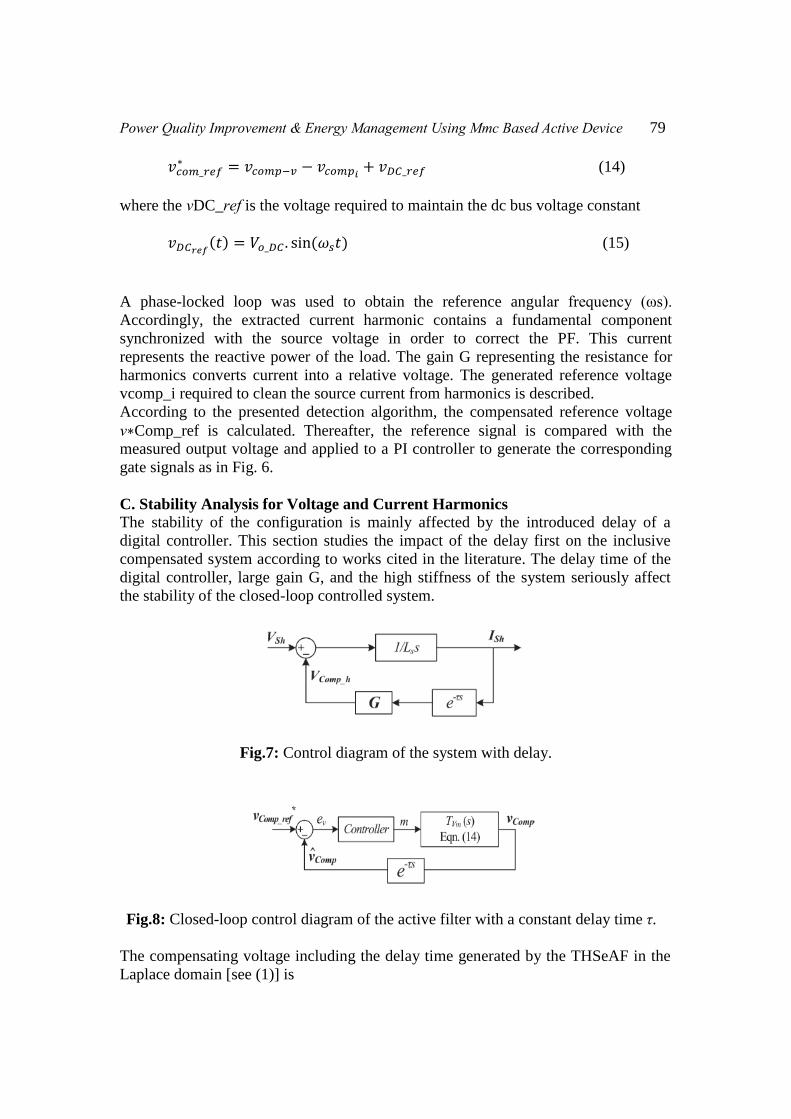
The compensating voltage for current harmonic compensation is obtained from
Fig.6: Block diagram of THSeAF and PI controller
Hereby, as voltage distortion at the load terminals is not desired, the voltage sag and
swell should also be investigated in the inner loop. The closed-loop equation (16)
allows to indirectly maintaining the voltage magnitude at the load side equal to VL∗
as a predefined value, within acceptable margins.
𝑣𝑐𝑜𝑚𝑝_𝑣 = 𝑣�̂� − 𝑉𝐿∗sin (𝜔𝑠𝑡) (13)
The entire control scheme for the THSeAF presented in Fig. 5 was used and
implemented in MATLAB/Simulink for real-time simulations and the calculation of
the compensating voltage.
Power Quality Improvement & Energy Management Using Mmc Based Active Device 79
𝑣𝑐𝑜𝑚_𝑟𝑒𝑓∗ = 𝑣𝑐𝑜𝑚𝑝−𝑣 − 𝑣𝑐𝑜𝑚𝑝𝑖
+ 𝑣𝐷𝐶_𝑟𝑒𝑓 (14)
where the vDC_ref is the voltage required to maintain the dc bus voltage constant
𝑣𝐷𝐶𝑟𝑒𝑓(𝑡) = 𝑉𝑜_𝐷𝐶 . sin(𝜔𝑠𝑡) (15)
A phase-locked loop was used to obtain the reference angular frequency (ωs).
Accordingly, the extracted current harmonic contains a fundamental component
synchronized with the source voltage in order to correct the PF. This current
represents the reactive power of the load. The gain G representing the resistance for
harmonics converts current into a relative voltage. The generated reference voltage
vcomp_i required to clean the source current from harmonics is described.
According to the presented detection algorithm, the compensated reference voltage
v∗Comp_ref is calculated. Thereafter, the reference signal is compared with the
measured output voltage and applied to a PI controller to generate the corresponding
gate signals as in Fig. 6.
C. Stability Analysis for Voltage and Current Harmonics The stability of the configuration is mainly affected by the introduced delay of a
digital controller. This section studies the impact of the delay first on the inclusive
compensated system according to works cited in the literature. The delay time of the
digital controller, large gain G, and the high stiffness of the system seriously affect
the stability of the closed-loop controlled system.
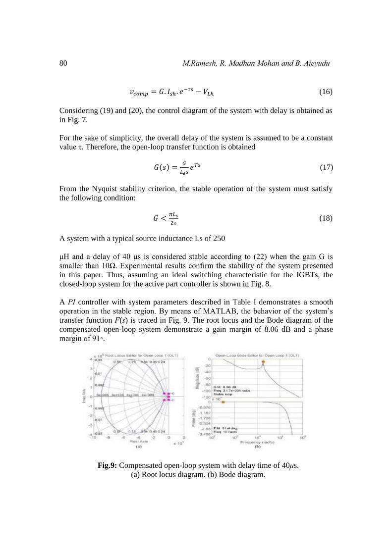
Fig.7: Control diagram of the system with delay.
Fig.8: Closed-loop control diagram of the active filter with a constant delay time τ.
The compensating voltage including the delay time generated by the THSeAF in the
Laplace domain [see (1)] is
80 M.Ramesh, R. Madhan Mohan and B. Ajeyudu
𝑣𝑐𝑜𝑚𝑝 = 𝐺. 𝐼𝑠ℎ. 𝑒−𝜏𝑠 − 𝑉𝐿ℎ (16)
Considering (19) and (20), the control diagram of the system with delay is obtained as
in Fig. 7.
For the sake of simplicity, the overall delay of the system is assumed to be a constant
value τ. Therefore, the open-loop transfer function is obtained
𝐺(𝑠) =𝐺
𝐿𝑒𝑠𝑒𝑇𝑠 (17)
From the Nyquist stability criterion, the stable operation of the system must satisfy
the following condition:
𝐺 <𝜋𝐿𝑠
2𝜏 (18)
A system with a typical source inductance Ls of 250
μH and a delay of 40 μs is considered stable according to (22) when the gain G is
smaller than 10Ω. Experimental results confirm the stability of the system presented
in this paper. Thus, assuming an ideal switching characteristic for the IGBTs, the
closed-loop system for the active part controller is shown in Fig. 8.
A PI controller with system parameters described in Table I demonstrates a smooth
operation in the stable region. By means of MATLAB, the behavior of the system’s
transfer function F(s) is traced in Fig. 9. The root locus and the Bode diagram of the
compensated open-loop system demonstrate a gain margin of 8.06 dB and a phase
margin of 91◦.
Fig.9: Compensated open-loop system with delay time of 40μs.
(a) Root locus diagram. (b) Bode diagram.
Power Quality Improvement & Energy Management Using Mmc Based Active Device 81
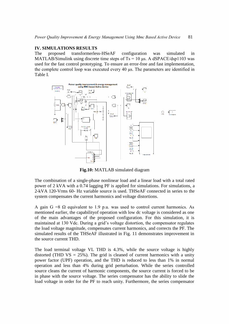
IV. SIMULATIONS RESULTS The proposed transformerless-HSeAF configuration was simulated in
MATLAB/Simulink using discrete time steps of Ts = 10 μs. A dSPACE/dsp1103 was
used for the fast control prototyping. To ensure an error-free and fast implementation,
the complete control loop was executed every 40 μs. The parameters are identified in
Table I.
Fig.10: MATLAB simulated diagram
The combination of a single-phase nonlinear load and a linear load with a total rated
power of 2 kVA with a 0.74 lagging PF is applied for simulations. For simulations, a
2-kVA 120-Vrms 60- Hz variable source is used. THSeAF connected in series to the
system compensates the current harmonics and voltage distortions.
A gain G =8 Ω equivalent to 1.9 p.u. was used to control current harmonics. As
mentioned earlier, the capabilityof operation with low dc voltage is considered as one
of the main advantages of the proposed configuration. For this simulation, it is
maintained at 130 Vdc. During a grid’s voltage distortion, the compensator regulates
the load voltage magnitude, compensates current harmonics, and corrects the PF. The
simulated results of the THSeAF illustrated in Fig. 11 demonstrates improvement in
the source current THD.
The load terminal voltage VL THD is 4.3%, while the source voltage is highly
distorted (THD VS = 25%). The grid is cleaned of current harmonics with a unity
power factor (UPF) operation, and the THD is reduced to less than 1% in normal
operation and less than 4% during grid perturbation. While the series controlled
source cleans the current of harmonic components, the source current is forced to be
in phase with the source voltage. The series compensator has the ability to slide the
load voltage in order for the PF to reach unity. Furthermore, the series compensator
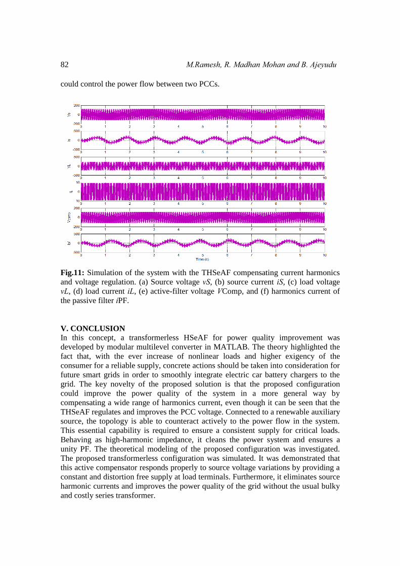
82 M.Ramesh, R. Madhan Mohan and B. Ajeyudu
could control the power flow between two PCCs.
Fig.11: Simulation of the system with the THSeAF compensating current harmonics
and voltage regulation. (a) Source voltage vS, (b) source current iS, (c) load voltage
vL, (d) load current iL, (e) active-filter voltage VComp, and (f) harmonics current of
the passive filter iPF.
V. CONCLUSION In this concept, a transformerless HSeAF for power quality improvement was
developed by modular multilevel converter in MATLAB. The theory highlighted the
fact that, with the ever increase of nonlinear loads and higher exigency of the
consumer for a reliable supply, concrete actions should be taken into consideration for
future smart grids in order to smoothly integrate electric car battery chargers to the
grid. The key novelty of the proposed solution is that the proposed configuration
could improve the power quality of the system in a more general way by
compensating a wide range of harmonics current, even though it can be seen that the
THSeAF regulates and improves the PCC voltage. Connected to a renewable auxiliary
source, the topology is able to counteract actively to the power flow in the system.
This essential capability is required to ensure a consistent supply for critical loads.
Behaving as high-harmonic impedance, it cleans the power system and ensures a
unity PF. The theoretical modeling of the proposed configuration was investigated.
The proposed transformerless configuration was simulated. It was demonstrated that
this active compensator responds properly to source voltage variations by providing a
constant and distortion free supply at load terminals. Furthermore, it eliminates source
harmonic currents and improves the power quality of the grid without the usual bulky
and costly series transformer.
Power Quality Improvement & Energy Management Using Mmc Based Active Device 83
REFERENCES
[1]. L. Jun-Young and C. Hyung-Jun, “6.6-kW onboard charger design using
DCM PFC converter with harmonic modulation technique and two-stage
dc/dc converter,” IEEE Trans. Ind.Electron., vol. 61, no. 3, pp. 1243– 1252,
Mar. 2014.
[2]. R. Seung-Hee, K. Dong-Hee, K. Min-Jung, K. Jong-Soo, and L. Byoung-
Kuk, “Adjustable frequency duty-cycle hybrid control strategy for full- bridge
series resonant converters in electric vehicle chargers,” IEEE Trans. Ind.
Electron., vol. 61, no. 10, pp. 5354–5362, Oct. 2014.
[3]. P. T. Staats, W. M. Grady, A. Arapostathis, and R. S. Thallam, “A statis- tical
analysis of the effect of electric vehicle battery charging on distribu-tion
system harmonic voltages,”IEEE Trans. Power Del., vol. 13, no. 2, pp. 640–
646, Apr. 1998.
[4]. A. Kuperman, U. Levy, J. Goren, A. Zafransky, and A. Savernin, “Battery
charger for electric vehicle traction battery switch station,” IEEE Trans. Ind.
Electron., vol. 60, no. 12, pp.5391– 5399, Dec. 2013.
[5]. Z. Amjadi and S. S. Williamson, “Modeling, simulation, control of an
advanced Luo converter for plug-in hybrid electric vehicle energy-storage
system,” IEEE Trans. Veh. Technol., vol. 60, no. 1, pp. 64–75, Jan. 2011.
[6]. H. Akagi and K. Isozaki, “A hybrid active filter for a three-phase 12-pulse
diode rectifier used as the front end of a medium-voltage motor drive,” IEEE
Trans. Power Del., vol. 27, no. 1, pp. 69–77, Jan. 2012.
[7]. A. F. Zobaa, “Optimal multiobjective design of hybrid active power filters
considering a distorted environment,” IEEETrans. Ind. Electron., vol. 61, no.
1, pp. 107–114, Jan. 2014.
[8]. D. Sixing, L. Jinjun, and L. Jiliang, “Hybrid cascaded H-bridge converter for
harmonic current compensation,” IEEETrans. Power Electron., vol. 28, no. 5,
pp. 2170–2179, May 2013.
[9]. M. S. Hamad, M. I. Masoud, and B. W. Williams,“Medium-voltage 12-
pulse converter: Output voltage harmonic compensation using a series APF,”
IEEE Trans. Ind. Electron., vol. 61, no. 1, pp. 43–52, Jan. 2014.
[10]. J. Liu, S. Dai, Q. Chen, and K. Tao, “Modelling and industrial application of
series hybrid active power filter,” IETPower Electron., vol. 6, no. 8, pp. 1707–
1714, Sep. 2013.
[11]. A. Javadi, H. Fortin Blanchette, and K. Al-Haddad,“An advanced control
algorithm for series hybrid active filter adopting UPQC behavior,” in Proc.
38th Annu. IEEE IECON, Montreal, QC, Canada, 2012, pp. 5318–5323.
[12]. O. S. Senturk and A. M. Hava, “Performance enhancement of the single-
phase series active filter by employing the load voltage waveform re-
construction and line current sampling delay reduction methods,”.

84 M.Ramesh, R. Madhan Mohan and B. Ajeyudu


![[] Transformer or Transformerless Ups[2003]{Koffler}](https://img.pdfslide.net/doc/110x75/577cc6881a28aba7119e864d/-transformer-or-transformerless-ups2003koffler.jpg)