Embed Size (px)
Citation preview
International Journal of Scientific & Engineering Research, Volume 6, Issue 11, November-2015 1041 ISSN 2229-5518
IJSER © 2015 http://www.ijser.org
Power Quality Improvement using STATCOM K. Jayavelu
Assistant Professor, Jeppiaar Institute of Technology [email protected]
Abstract: The paper describes an advanced approach to power quality enhancement, mainly to flicker mitigation. There is described the standard STATCOM device added by an energy storage in its DC circuit. Its function is then discussed and modelled for active power compensation in addition to the classical reactive power compensation. A case study is provided for an industrial plant with 60 MVA electric arc furnace producing power disturbances, namely flicker.
Key words: STATCOM, active power compensation, power quality, flicker, industrial plant.
—————————— —————————— 1. Introduction The concept of power quality includes the quality of the supplying voltage with respect to interruptions, voltage dips, unbalance, harmonics and flicker. Limits of the power quality parameters are determined in international standards and countries transmission and distribution codes. Large loads with non-linear characteristics, consumptions variable in time and high-voltage devices using semiconductor technology are often the source of interferences in the power grid. One of the industrial devices could be an electric arc furnace (EAF) which has a character of chaotically and dynamically variable load and thus affects the power quality negatively usually in a distribution system. Nowadays, power semiconductor devices are already at such both voltage and current levels that they can be utilized MV and HV applications. FACTS devices using power electronics based converters have the task to increase the reliability and quality of electricity supply for consumers [1]. Improving the power quality is usually achieved by means of reactive power control, load symmetrisation and active filtering of nonlinear loads harmonics. The FACTS devices ability to control bus voltage magnitudes and phase angles depends on their rating and applied control strategies. A few studies in the past dealt with the placement and modelling of FACTS devices for voltage sag mitigation purposes. They were mostly focused on the load characteristics and simulations were interested in one individual bus. This approach,
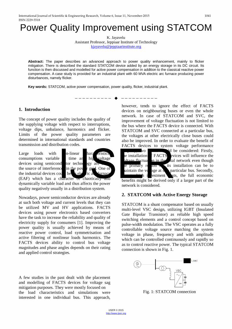
however, tends to ignore the effect of FACTS devices on neighbouring buses or even the whole network. In case of STATCOM and SVC, the improvement of voltage fluctuation is not limited to the bus where the FACTS device is connected. With STATCOM and SVC connected at a particular bus, the voltages at other electrically close buses could also be improved. In order to evaluate the benefit of FACTS devices to system voltage performance properly, two points should be considered: Firstly, the installation of FACTS devices will influence the voltage fluctuation in the total network even though the primary reason for its installation can be to maintain the voltage at one particular bus. Secondly, due to high investment costs, the full economic benefits might be derived only if a larger part of the network is considered. 2. STATCOM with Active Energy Storage STATCOM is a shunt compensator based on usually multi-level VSC design, utilizing IGBT (Insulated Gate Bipolar Transistor) as reliable high speed switching elements and a control concept based on pulse-width modulation. The VSC operates as a fully controllable voltage source matching the system voltage in phase, frequency and with amplitude which can be controlled continuously and rapidly so as to control reactive power. The typical STATCOM connection is shown in Fig. 1.
Fig. 1: STATCOM connection
IJSER
International Journal of Scientific & Engineering Research, Volume 6, Issue 11, November-2015 1042 ISSN 2229-5518
IJSER © 2015 http://www.ijser.org
STATCOM allows voltage stabilization, improvement of power factor and dynamic control at the point of connection to industrial load using reactive power compensation. This is not enough in situations when a variable load is connected to the grid and produces voltage fluctuations. In this case, using additional active power compensation is required because the voltage drop is caused by reactive and active power consumption too (1).
Equation (1) has upper sign “+” in real part for inductive and bottom “-” for capacitive load character. We can see from this formula that voltage drop cannot be eliminated just by compensating reactive power. However, using active power injection can eliminate small fast voltage disturbances during variable load operation. Such disturbances are the main cause of flicker in transmission and distribution grids. STATCOM with active power compensation could be realized by adding an element which can inject and consume active power, i.e. to store the active energy. It can be reached by parallel connection of a battery to the DC capacitor. STATCOM uses VSC technology which enables 4-qudrant operation in case of active power exchange possibility. It makes possible to convert AC to DC and back for active current. Usage of active power compensation has a big potential for many applications, such as:
• voltage and power compensation in distribution and transmission systems
• power compensation during short-circuits and network reconfigurations
• stability increasing during grid reconfigurations or generator failures
• compensation of voltage dip during short time failure
One of the problems which have to be solved is VSC control for active power flow. Classical STATCOM (Q-compensation) control is realized by means of difference between the converter output voltage and the grid voltage magnitudes. Active power compensation control can be realized by phase angle differences. In this case, phasor measurement units (PMU) can be used. Another problem is a dynamic characteristic of battery, fast reaction to power changes in the grid and their compensation. However modern technologies and trends in battery development are promising. A suitable energy storage system for STATCOM depends on its application. In case of the function to compensate active power fluctuations in terms of minutes, e.g. at renewable sources, a huge battery is supposed to be the right solution. This is also presented by some manufacturers as a device capable to accumulate the active power in the range of tens of MW for tens of minutes. In case of power quality tasks, other different technologies seems to be promising like capacitors, ultra-capacitors, flywheels or some new battery types.
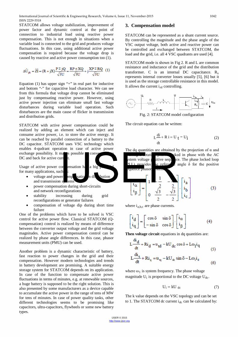
3. Compensation model STATCOM can be represented as a shunt current source. By controlling the magnitude and the phase angle of the VSC output voltage, both active and reactive power can be controlled and exchanged between STATCOM, the load and the grid, i.e. all 4 VSC quadrants are used [4]. STATCOM mode is shown in Fig 2. R and L are common resistance and inductance of the grid and the distribution transformer. C is an internal DC capacitance. Rs represents internal converter losses usually [5], [6] but it is used as the storage controllable resistance in this model. It allows the current ird controlling.
Fig. 2: STATCOM model configuration The circuit equation can be written:
L di + R i = U t − Ui (2)
dt
The dq quantities are obtained by the projection of α and β along a rotating phasor locked in phase with the AC system voltage positive sequence. The phase locked loop (PLL) provides the reference angle δ for the positive sequence phasor system.
where ia,b,c are phase currents.
Then voltage circuit equations in dq quantities are:
where ω1 is system frequency. The phase voltage magnitude Ui is proportional to the DC voltage Udc.
Ui = kU dc (7) The k value depends on the VSC topology and can be set to 1. The STATCOM dc current idc can be calculated by:
IJSER
International Journal of Scientific & Engineering Research, Volume 6, Issue 11, November-2015 1043 ISSN 2229-5518
IJSER © 2015 http://www.ijser.org
The active and reactive power flow at STATCOM bus can be expressed:
Based on the equivalent circuit, STATCOM dynamics can be expressed in dq reference frame:
By setting all the derivatives to zero, the steady state equation can be obtained:
Solving the equation (11):
In situations when reactive power compensation is not enough, voltage control can be achieved by active power control. It can be done by controlling Rs which represents active power storage. Direction of Id depends on if storage is charging or discharging. 4. STATCOM control:
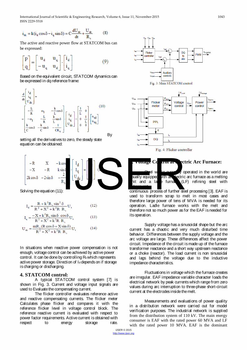
A typical STATCOM control system [7] is shown in Fig. 3. Current and voltage input signals are used to Evaluate the compensating current.
The flicker controller evaluates reference active and reactive compensating currents. The flicker meter Calculates phase flicker and compares it with the reference flicker level in voltage control block. The reference reactive current is evaluated with respect to power factor requirements. Active current is obtained with respect to energy storage rate.
5. Voltage Control at Electric Arc Furnace:
Steel works currently operated in the world are
usually equipped with an electric arc furnace as a melting unit and a ladle furnace (LF) refining steel with subsequent continuous process of further steel processing [3]. EAF is used to transform scrap to melt in most cases and therefore large power of tens of MVA is needed for its operation. Ladle furnace works with the melt and therefore not so much power as for the EAF is needed for its operation.
Supply voltage has a sinusoidal shape but the arc
current has a chaotic and very much disturbed time behavior. Differences between the supply voltage and the arc voltage are large. These differences affect the power circuit. Impedance of the circuit is made up of the furnace transformer reactance and a short way upstream reactance or a choke (reactor). The load current is non sinusoidal and lags behind the voltage due to the inductive impedance characteristics.
Fluctuations in voltage which the furnace creates
are irregular. EAF impedance variable character loads the electrical network by peak currents which range from zero values during arc interruption to three-phase short-circuit current at the electrodes inside the melt.
Measurements and evaluations of power quality
in a distribution network were carried out for model verification purposes. The industrial network is supplied from the distribution system of 110 kV. The main energy consumer is EAF with the rated power 60 MVA and LF with the rated power 10 MVA. EAF is the dominant
IJSER
International Journal of Scientific & Engineering Research, Volume 6, Issue 11, November-2015 1044 ISSN 2229-5518
IJSER © 2015 http://www.ijser.org
electrical energy consumer. Thus it affects the power quality to all connected customers in this area. Further measurements were carried out in the industrial network within the plant 22 kV which is involved in both arc furnaces EAF and LF. During the measurements all electrical quantities were stored as 10-periods (200 ms) values. A compensation device SVC is already connected in parallel which is used to improve power factor, to reduce harmonics and flicker. The connection diagram including the proposed STATCOM is shown in Fig. 5.
Fig. 5: Diagram of connection EAF with compensation using SVC and STATCOM
Calculations are made for the 110/22 kV transformer with parameters 63 MVA, uk = 12 %. EAF has different operating modes. One of the modes is taken to provide a simulation. Fast changes in power caused by load currents fluctuation do not demand high energy storage. Hence a supercapacitor is chosen as active power source. Another important factor is the number of recharges which are almost unlimited. This is important for this application. A 30 minute period is chosen for the simulation with the first part presented in more details marked as red in Fig. 6. This period represents a typical EAF operational cycle. Power factor correction is provided only with SVC in order to compare the results with measurements and show the positive effect of active power compensation. The calculation is made only for single phase system due to the symmetrical loads.
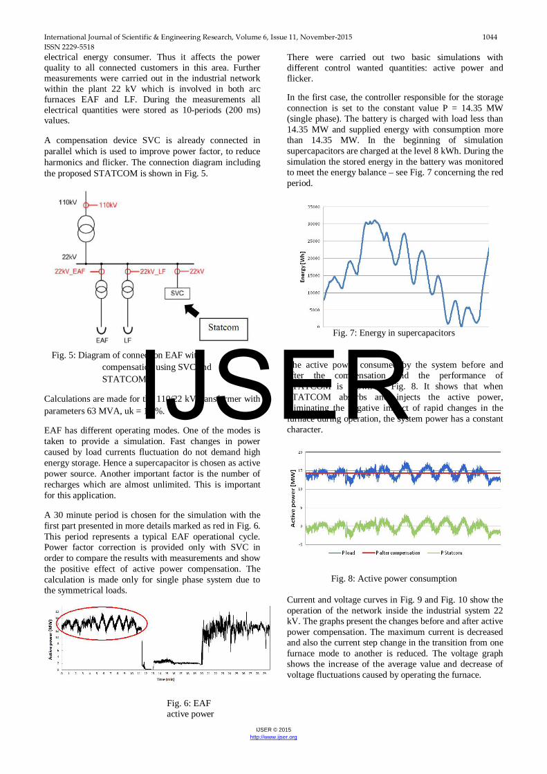
There were carried out two basic simulations with different control wanted quantities: active power and flicker. In the first case, the controller responsible for the storage connection is set to the constant value P = 14.35 MW (single phase). The battery is charged with load less than 14.35 MW and supplied energy with consumption more than 14.35 MW. In the beginning of simulation supercapacitors are charged at the level 8 kWh. During the simulation the stored energy in the battery was monitored to meet the energy balance – see Fig. 7 concerning the red period.
Fig. 7: Energy in supercapacitors The active power consumed by the system before and after the compensation and the performance of STATCOM is shown in Fig. 8. It shows that when STATCOM absorbs and injects the active power, eliminating the negative impact of rapid changes in the furnace during operation, the system power has a constant character.
Fig. 8: Active power consumption
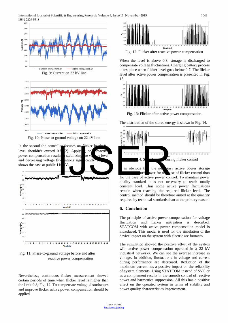
Current and voltage curves in Fig. 9 and Fig. 10 show the operation of the network inside the industrial system 22 kV. The graphs present the changes before and after active power compensation. The maximum current is decreased and also the current step change in the transition from one furnace mode to another is reduced. The voltage graph shows the increase of the average value and decrease of voltage fluctuations caused by operating the furnace.
Fig. 6: EAF active power
IJSER
International Journal of Scientific & Engineering Research, Volume 6, Issue 11, November-2015 1045 ISSN 2229-5518
IJSER © 2015 http://www.ijser.org
consumption
IJSER
International Journal of Scientific & Engineering Research, Volume 6, Issue 11, November-2015 1046 ISSN 2229-5518
IJSER © 2015 http://www.ijser.org
Fig. 9: Current on 22 kV line
Fig. 10: Phase-to-ground voltage on 22 kV line In the second the controller focuses on flicker level, Pst level shouldn’t exceed 0.8 [2]. Applying only reactive power compensation results in stabilizing the voltage level and decreasing voltage fluctuations significantly. Fig. 11 shows the case at public 110 kV. Fig. 11: Phase-to-ground voltage before and after
reactive power compensation Nevertheless, continuous flicker measurement showed certain periods of time when flicker level is higher than the limit 0.8, Fig. 12. To compensate voltage disturbances and improve flicker active power compensation should be applied.
Fig. 12: Flicker after reactive power compensation When the level is above 0.8, storage is discharged to compensate voltage fluctuations. Charging battery process takes place when flicker level goes below 0.7. The flicker level after active power compensation is presented in Fig. 13.
Fig. 13: Flicker after active power compensation The distribution of the stored energy is shown in Fig. 14.
Fig. 14: Stored energy during flicker control It is obvious that the necessary active power storage capacity is much lower for the case of flicker control than for the case of active power control. To maintain power quality standard it is not necessary to reach totally constant load. Thus some active power fluctuations remain when reaching the required flicker level. The control method should be therefore aimed at the quantity required by technical standards than at the primary reason. 6. Conclusion The principle of active power compensation for voltage fluctuation and flicker mitigation is described. STATCOM with active power compensation model is introduced. This model is used for the simulation of the device impact on the system with electric arc furnaces. The simulation showed the positive effect of the system with active power compensation operated in a 22 kV industrial networks. We can see the average increase in voltage. In addition, fluctuations in voltage and current during performance are decreased. Reduction of the maximum current has a positive impact on the reliability of system elements. Using STATCOM instead of SVC or as a complement results in the smooth control of reactive power and harmonics suppression. All this has a positive effect on the operated system in terms of stability and power quality characteristics improvement.
IJSER
International Journal of Scientific & Engineering Research, Volume 6, Issue 11, November-2015 1047 ISSN 2229-5518
IJSER © 2015 http://www.ijser.org
The dimensioning of the active power storage is given by the controlled quantity. From the economical point of view it is suitable to control flicker directly which allows to have a smaller energy storage capacity because of technical standards requirements. To keep a constant load power is a very ideal case but an over dimensioned one. The paper was focused on a particular industrial network case and one bus with the connected EAF. The future work should be aimed at multibus optimization tasks if the a disturbing consumer affects a larger distribution or transmission system part. References [1] Yanushkevich, A.: Using STATCOM for Active Power
Compensation: Power Quality Improvement in Distribution System, Poster 2011, Praha: ČVUT v Praze, FEL, p. 1-4., ISBN 978-80-01-04806-1
[2] IEC 61000-3-7, Assessment of emission limits for the connection of fluctuating installations to MV, HV and EHV power systems.
[3] Statcom for arc furnace and flicker compensation, CIGRE Technical Brochure 237, 2003.
[4] Yanushkevich A, Tlustý J: Active Power Compensation in Industrial Applications Using Statcom with Supercapacitors, 2012 IEEE 12th International Conference on Probabilistic Methods Applied to Power Systems, PMAPS 2012, p. 1-4
[5] Zhiping Yang ; Crow, M.L. ; Chen Shen ; Lingli Zhang: The steady state characteristics of a StatCom with energy storage. Power Engineering Society Summer Meeting, 2000. IEEE. Publication Year: 2000 , Page(s): 669- 674 vol. 2
[6] M. S. Ballal, H. M. Suryawanshi, and T. Venkateswara Reddy, “Mitigation of Voltage Dip and Voltage Flickering by Multilevel D-STATCOM,” Advances in Power Electronics, vol. 2012, Article ID 871652, 11 pages, 2012.
[7] Hailian X., Angquist L., Nee, H.-P. Design and Analysis of a Controller for a Converter Interface Interconnecting an Energy Storage With the Dc Link of a VSC. Power Systems, IEEE Transactions on (Volume:25, Issue: 2 ). Publication Year: 2010 , Page(s): 1007 - 1015
IJSER