Embed Size (px)
Citation preview

Power Quality of DistributedWind Projects in the TurbineVerification Program
September 2001 • NREL/CP-500-30407
J. GreenNational Renewable Energy Laboratory
J. VandenBosche, T. Lettenmaier, and G. RandallGlobal Energy Concepts, LLC
Presented at AWEA's WINDPOWER 2001 ConferenceWashington, D.C.June 4 – June 7, 2001
National Renewable Energy Laboratory1617 Cole BoulevardGolden, Colorado 80401-3393NREL is a U.S. Department of Energy LaboratoryOperated by Midwest Research Institute •••• Battelle •••• Bechtel
Contract No. DE-AC36-99-GO10337

NOTICEThe submitted manuscript has been offered by an employee of the Midwest Research Institute (MRI), acontractor of the US Government under Contract No. DE-AC36-99GO10337. Accordingly, the USGovernment and MRI retain a nonexclusive royalty-free license to publish or reproduce the publishedform of this contribution, or allow others to do so, for US Government purposes.
This report was prepared as an account of work sponsored by an agency of the United Statesgovernment. Neither the United States government nor any agency thereof, nor any of their employees,makes any warranty, express or implied, or assumes any legal liability or responsibility for the accuracy,completeness, or usefulness of any information, apparatus, product, or process disclosed, or representsthat its use would not infringe privately owned rights. Reference herein to any specific commercialproduct, process, or service by trade name, trademark, manufacturer, or otherwise does not necessarilyconstitute or imply its endorsement, recommendation, or favoring by the United States government or anyagency thereof. The views and opinions of authors expressed herein do not necessarily state or reflectthose of the United States government or any agency thereof.
Available electronically at http://www.doe.gov/bridge
Available for a processing fee to U.S. Department of Energyand its contractors, in paper, from:
U.S. Department of EnergyOffice of Scientific and Technical InformationP.O. Box 62Oak Ridge, TN 37831-0062phone: 865.576.8401fax: 865.576.5728email: [email protected]
Available for sale to the public, in paper, from:U.S. Department of CommerceNational Technical Information Service5285 Port Royal RoadSpringfield, VA 22161phone: 800.553.6847fax: 703.605.6900email: [email protected] ordering: http://www.ntis.gov/ordering.htm
Printed on paper containing at least 50% wastepaper, including 20% postconsumer waste
1
POWER QUALITY OF DISTRIBUTED WIND PROJECTS IN THETURBINE VERIFICATION PROGRAM
Jim GreenNational Renewable Energy Laboratory
1617 Cole BoulevardGolden, CO 80401-3393 USA
John VandenBosche, Terry Lettenmaier, and Gordon RandallGlobal Energy Concepts, LLC
5729 Lakeview Dr. NE, Suite 100Kirkland, WA 98033
[email protected]@globalenergyconcepts.com
Tom WindWind Utility Consulting
Jefferson, IA515/386-3405
Abstract
The Electric Power Research Institute/U.S. Department of Energy (EPRI/DOE) Turbine VerificationProgram (TVP) includes four distributed wind generation projects connected to utility distribution feederslocated in Algona, Iowa; Springview, Nebraska; Glenmore, Wisconsin; and Kotzebue, Alaska. The TVPhas undertaken power quality measurements at each project to assess the impact that power quality has onthe local utility grids. The measurements and analysis were guided by the draft IEC 61400-21 standardfor power quality testing of wind turbines. The power quality characteristics measured include maximumpower, distribution feeder voltage regulation, reactive power, and harmonics. This paper describes theapproach to the measurements, the unique electrical system features of the four projects, and anassessment of measured power quality relative to limits prescribed by standards. It also gives anecdotalstories from each project regarding the impact of power quality on the respective distribution feeders.
Introduction
EPRI and DOE initiated the TVP in 1992 to evaluate prototype advanced wind turbines and to provide abridge from development programs to early production models of commercial wind turbines. Central andSouth West Services in Texas and Green Mountain Power Corporation in Vermont were chosen through acompetitive solicitation to host the first two TVP projects. TVP’s involvement in these projects ended in1999 and 2000, respectively.
Two public utility partnerships were also selected to participate in the TVP in 1997 through a Request forProposals, which focused on evaluating distributed wind generation using turbines connected directly tothe electric distribution system. The Iowa Distributed Wind Generation Project in Algona, Iowa, and theNebraska Distributed Wind Generation Project in Springview, Nebraska, were built in the fall of 1998.

2
In addition to the projects chosen through TVP solicitations, four utility wind facilities to date have joinedthe TVP as “associate” projects. These projects receive limited funding from the program but benefitfrom information exchange and technical assistance. The Associate TVP projects include the KotzebueWind Energy Project in Kotzebue, Alaska; the Wisconsin Low-Wind-Speed Turbine Project in Glenmore,Wisconsin; the York Research Corporation Big Spring Wind Farm in Big Spring, Texas; and theTennessee Valley Authority Buffalo Mountain wind project in eastern Tennessee. The wind turbines inboth the Kotzebue and Glenmore projects are interconnected to distribution feeders.
A primary objective for four of the distributed TVP projects is to examine issues related to distributedgeneration. Relative to the large wind farm concept, distributed wind generation using “clusters” of windturbines is seen by some to offer lower risk and a more flexible way for utilities to participate in windenergy projects. Such projects are typically connected directly to a distribution line without a dedicatedsubstation, which reduces costs. They may be operated independently or from a central, remote site. Asan alternative to the traditional U.S. utility approach of expanding centralized generation, the distributeddevelopment model offers opportunities for utilities to address system expansion issues and allowssmaller, modular capacity assets to be located nearer to load centers. For a thorough discussion ofdistributed wind power, refer to Distributed Wind Power Assessment by the National Wind CoordinatingCommittee (NWTC 2001).
Power Quality Characteristics
Power quality is of particular interest for distributed wind applications for two primary reasons. First, thewind turbines are connected to distribution feeders rather than to transmission lines. Distribution feedersare not as electrically “stiff,” and are less able to deal with a fluctuating source like a wind turbine.(Stiffness refers to the ability of a feeder to maintain constant voltage during periods of high current.)Secondly, utility customers are typically located on the same distribution line, sometimes relatively closeto the wind turbine(s). Without intervening substations or transmission lines, these customers will bemore directly exposed to power quality problems should any exist. The variations in output powerinherent with wind turbines caused by changes in wind speed, turbulence, wind turbine switching events(e.g. starting, stopping, and switching speeds), and other phenomena have the potential to degrade thepower quality of a distribution feeder.
A new international standard for wind turbine power quality is under development by the InternationalElectrotechnical Commission (IEC), IEC 61400-21, “Wind Turbine Generator Systems–Part 21:Measurement and Assessment of Power Quality Characteristics of Grid Connected Wind Turbines” (IEC2000). When published, this document will provide a uniform methodology for measuring power qualitycharacteristics of grid-connected wind turbines, including peak power output, reactive power, voltagefluctuations (flicker), and harmonics. These wind turbine electrical characteristics, through interactionwith the electrical grid, exert the most influence on the power quality of a particular wind turbineinstallation.
This study follows the approach of IEC 61400-21 to the extent possible with the data set available to us.The one characteristic we cannot address is voltage fluctuations or flicker. Measurement of flicker usingthe IEC method requires very high sampling rates, up to 3,000 Hz, which are beyond the capabilities ofthe data systems being used to monitor these four projects. In addition to the power quality characteristicsincorporated in IEC 61400-21, we will also address the voltage regulation of the individual distributionfeeders. We will present measurements made on individual wind turbines in the four distributed windgeneration projects and compare the data, where applicable, to recognized power quality limits. It isimportant to note that the pending IEC standard does not provide any criteria for evaluating powerquality. We will use American National Standards Institute (ANSI) C84.1-1995 for limits on distribution
3
feeder voltage (ANSI 1995). Recommended limits on harmonics are taken from the Institute of Electricaland Electronics Engineers (IEEE) Std 519-1992 (IEEE 1992).
Data Acquisition
Phaser® power transducers manufactured by Second Wind and installed at the output terminals ofindividual wind turbines provided the data for this study. These transducers were installed on the low-voltage side of the wind turbine transformers. The data was collected and recorded through AdvancedDistributed Monitoring Systems also from Second Wind. This SCADA (supervisory control and dataacquisition) hardware was standard on each wind turbine at each TVP site which eliminated any need toinstall extra equipment in order to obtain the data for this study. The Phasers each reported 1-secondaverage data, and 10-minute averages, maximums, and minimums were recorded by the SCADA.
The power quality of a single turbine at each project site has been evaluated. The lengths of the data setswere selected to be in compliance with IEC 61400-21, which prescribes a minimum of five 10-minutetime series of data for each 1-meter per second (m/s)-wide wind speed “bin” from cut-in wind speed (3 to4 m/s, depending on turbine type) to 15 m/s wind speed. For this analysis, we selected data only fromperiods when all project turbines were online and producing power. For the Algona and Springviewprojects, a two-week period was sufficient to meet the minimum data requirements. A two-month periodwas needed to accumulate sufficient data while all ten turbines were operating at the Kotzebue project.No meteorological tower was available for the Glenmore project, necessitating the use of the turbinenacelle anemometer for wind-speed measurements. Data from the nacelle anemometer did not indicatewind speeds up to the required upper speed of 15 m/s. However, the nacelle anemometer typically readslow while the turbine is operating, and it is expected that sufficient data is available at high wind speedsbased on the availability of a large amount of data when the turbine was producing rated or higher-than-rated power. Therefore, we used two weeks of data for this project.
Distributed Wind Generation Projects
Each of the four TVP distributed wind projects represents a unique wind turbine and distribution systemcombination, as summarized in Table 1. The distribution feeder lengths, location of the projects on thefeeders, and stiffness of the electrical systems (represented by short-circuit MVA) are different for eachproject. The maximum wind power penetration—the portion of the feeder or substation load served bywind power—varies widely. There is also variation in the wind turbine technologies used.
Both the Algona and Springview projects use Zond Z50, 750-kW turbines, with variable-speed, powerelectronic control of doubly-fed induction generators. These turbines use pitch-controlled blades. Thepower electronic control in each turbine corrects the power factor to a user-adjustable value. Althoughthe same turbines are used in both projects, the distribution feeder characteristics are quite different. TheAlgona project is located near the end of a 6-mile-long, weak distribution feeder. The rated output of thethree wind turbines, 2,250 kW, is much larger than the minimum feeder load, 250 kW. In addition, thesewind turbines may at times exceed 100% penetration on the substation. The Springview project is locatedvery close to its substation at the beginning of a very long distribution feeder (200 total feeder miles).Like Algona, the minimum substation load is less than the rated project output, so reverse power flowthrough the substation will occur when there are high winds and low load (EPRI 1999a).
The Glenmore project uses two 600-kW Tacke turbines with direct-line-connected, two-speed inductiongenerators and stall-controlled blades. Power factor is corrected by sets of four switched capacitors ineach wind turbine. The project is located in the middle of a 12-mile, relatively stiff distribution feeder(EPRI 1998). This project has the lowest penetration on the distribution feeder. The rated output of thetwo turbines is only 70% of the minimum load on the feeder.

4
TABLE 1. SUMMARY OF DISTRIBUTED WIND GENERATION PROJECTS
Project Algona,Iowa
Springview,Nebraska
Glenmore,Wisconsin
Kotzebue,Alaska
Rated power - project 2,250 kW 1,500 kW 1,200 kW 660 kW
Number of turbines 3 2 2 10
Rated power - per turbine 750 kW 750 kW 600 kW 66 kW
Turbine model Zond Z50 Zond Z50 Tacke TW-600e AOC 15/50
Generator Wound rotorinduction
Wound rotorinduction
Squirrel cageinduction (4/6
pole switchable)
Squirrel cageinduction
Frequency converter PWM inverter PWM inverter None None
Control method Variable speed;pitch control
Variable speed;pitch control
Two speeds;stall control
Fixed speed;stall control
Power factor correctionPower electronicWinter: PF=.93
Summer: PF=.90
Power electronicPF = 1.0
Switchedcapacitors Fixed capacitors
Reactive power (rated) User set User set 122 kVAR 15 kVAR
Distribution voltage 13.8 kV 12.5 kV 24.9 kV 12.5 kV
Distance to substation 6 miles 1 mile 6 miles 5 miles
Feeder miles beyondturbines 0 200 miles 6 miles 0
Feeder load
Minimum 250 kW Not available 1,700 kW 100 kW
Average 400 kW Not available 5,600 kW Not available
Maximum 1,000 kW Not available 8,700 kW 300 kW
Substation load
Minimum 2,000 kW 0 2,700 kW 1,800 kW
Average 5,500 kW 900 kW 8,400 kW 2,500 kW
Maximum 8,200 kW 3,500 kW 13,500 kW 3,900 kW
Short circuit MVA 16.2 MVA 25 MVA 35 MVA 12 MVA

5
The Kotzebue project uses ten 66-kW Atlantic Orient 15/50 wind turbines. These are constant-speedwind turbines with direct-line-coupled induction generators and stall-controlled blades. Power factor iscorrected by fixed capacitors installed on each wind turbine. The project is located near the end of a five-mile distribution feeder. The Kotzebue electric system is an isolated grid, powered by a diesel generatingplant with six generators. The minimum load on this grid is about 1,800 kW. The wind powerpenetration into this grid has been as high as 35% for a 10-minute period. Only one or two of the dieselgenerators typically supply power at any time; the rest are necessary for redundancy. The grid voltage ofthe Kotzebue system is not as stable as for the other three TVP projects (EPRI 1999b).
Power Quality Measurements
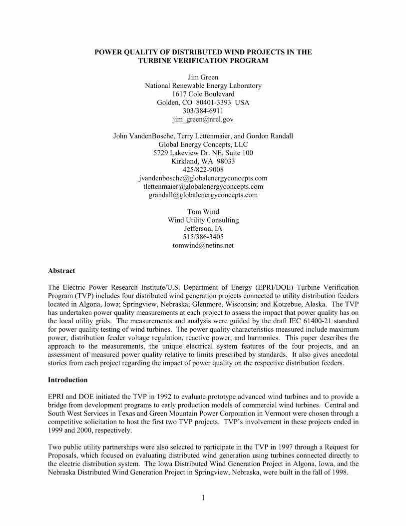
Peak Power—Comparisons of rated nominal power, rated peak power, and measured peak power for thefour sites are shown in Figure 1. The turbine rated power information, both nominal and peak, are takenfrom the manufacturer’s literature. The measured power data are the maximum 1-second and 10-minuteaverages for the selected turbine in each project. In keeping with IEC 61400-21, these values were allnormalized by dividing the value by the rated power of each wind turbine. Note the comparisons of ratedpeak power to the 10-minute measured peak power. This is a measurement of the highest sustainedoutput from the wind turbine, which could affect power system components such as transformers andconductors whose design limits are based on thermal considerations. For the turbines at Algona andSpringview, the measured peak power is essentially the same as the rated peak power. At Glenmore andKotzebue, the rated peak power is exceeded, but by less than 5%. These excursions above rated powerhave not caused problems at any of the sites. However, the interconnection design process shouldconsider both the 10-minute and 1-second power output values.
FIGURE 1. COMPARISON OF PERMITTED AND MEASURED PEAK POWER
90%
100%
110%
120%
130%
140%
150%
160%
Algona Springview Glenmore Kotzebue
Rated Nominal Power
Rated Peak Power
Measured Peak Power,10-min
Measured Peak Power,1-sec

6
Feeder Voltage Regulation—The range of 10-minute average voltages observed at the terminals of eachwind turbine is plotted in Figure 2. These ranges indicate the ability of the particular distribution feederto maintain the desired system voltage during wind power generation. For comparison, the voltage rangespecified in ANSI C84.1 (service voltages, Range A) is also shown. In all four cases, the feeders are ableto maintain voltages well within the ANSI limits. Kotzebue shows the largest voltage range of any of theprojects. This might be expected given that the Kotzebue utility is a relatively small, isolated grid. Thesubstation serving the wind turbine is, in effect, the entire grid. Even in this situation, voltage regulationis acceptable.
FIGURE 2. FEEDER VOLTAGE REGULATION
Reactive Power—Reactive power is presented as power factor plotted against percent of rated power inFigure 3. At Algona, the power factor is nearly constant at 93% for power levels above 20% of rated.This is a result of the Zond Z50 turbines at this site actively controlling their power factor. The powerfactor setpoints are changed seasonally, as noted in Table 1, to minimize voltage changes in the feeder.(The Algona data plotted in Figure 3 are from a winter season.) The power factor for the Springviewwind turbine, another Zond Z50, also has a nearly constant value above 20% of rated power. It hoversjust below the setpoint of 100%.
The wind turbine at Glenmore uses an induction generator, and the power factor is controlled byswitching banks of low-voltage capacitors on and off. This is a less accurate control method and resultsin more variation in the reactive power requirements and the resulting power factor. Nevertheless, thecontrol scheme maintains a relatively constant power factor from 20% output up to full load. The windturbine at Kotzebue also uses an induction generator, but has only one fixed bank of capacitors. Again,the power factor control is quite good.
There are no standards for reactive power or power factor, however good practice dictates that individualdevices on a power system should operate with power factor above 0.9. Three of the four wind turbines
450
500
550
600
650
Volta
ge
Algona, IASustainedOperatingVoltages
Springview, NESustainedOperatingVoltages
Kotzebue, AKSustainedOperatingVoltages
Glenmore, WISustainedOperatingVoltages
ANSI C84.1Service Voltage
Range A for Nominal 480 V
System
ANSI C84.1Service Voltage
Range A for Nominal 600 V
System

7
operate with power factors above 0.96 over most of their operating range. The fourth, at Algona, wasintentionally operated at a lower power factor as noted above.
FIGURE 3. POWER FACTOR VS. POWER LEVEL
Harmonics—Total demand distortion (TDD) of the current measured at the four sites has been plottedagainst percent of rated power in Figure 4, along with the 5% TDD limit recommended in IEEE 519.TDD is the ratio of the root-mean-square value of the total harmonic current to the rated current. TheTDD for the Zond Z50 wind turbines at Algona and Springview are remarkably low for variable-speedwind turbines using electronic power converters. Power electronics can be significant sources ofharmonics depending upon their design. The TDD averages less than 1.5% for Algona and less than 1.0%for Springview. The differences in the ranges and shape of the data are likely due to the differences inpower converter switching frequencies (Springview has a higher frequency) and in the power factor setpoints.
The TDD for the Glenmore wind turbine increases with power level and reaches 5% near peak power. Itis surprising that the TDD for this wind turbine, which uses an induction generator, is actually higher thanfor the wind turbines with power electronics. The Glenmore turbine does use power electronics for soft-starting of its generator. But, this operation lasts for only a few seconds and should not contribute to the10-munute-average distortion values reported here. The TDD for the Kotzebue wind turbine averagesabout 3% over most of its range of operation. In all cases, the TDD has not caused any problems on thedistribution systems to which they were connected.
0.84
0.86
0.88
0.90
0.92
0.94
0.96
0.98
1.00
0 10 20 30 40 50 60 70 80 90 100Output Power, % of Rated
Pow
er F
acto
r
Springview
Glenmore
Kotzebue
Algona

8
FIGURE 4. TOTAL DEMAND DISTORTION OF CURRENT VS. POWER LEVEL
Utility Power Quality Experience
While measurements are the best basis for evaluating power quality, anecdotal stories from the hostutilities are also useful in understanding the impacts of the projects. When the four TVP distributed windprojects were installed, there was little documented experience in the U.S. with utility-scale wind turbinesconnected directly to distribution lines. Therefore, the host utilities each had some concerns that theturbines might have a negative impact. However, none of the host utilities have reported any customercomplaints nor have they observed any power quality problems resulting from the wind turbines.
The wind turbines in Springview created noise on the local telephone lines when they were first installed.This was perplexing because there were no telephone connections to the site and the phone line wasphysically located across a highway from the distribution line. The phone noise issue was solved througha combination of increasing the switching frequency of the turbines’ power electronics converters from1,000 Hz to 2,000 Hz, modifying the turbines’ ground system, connecting a ground tap on the turbines’transformers, and adding additional capacitor filters on the distribution line (EPRI 1999a and EPRI Oct.2000). The engineer planning the Algona project was concerned about possible voltage variations on thedistribution line after the turbines were installed. In response to his concerns, and at his request, Enrondesigned a new power factor controller for their turbines. Measurements taken after the turbines wereinstalled indicated that the turbines were well behaved and did not cause unacceptable flicker levels orvoltage level changes (EPRI 1999a). One particularly sensitive load in Algona is the local hospital, whichis connected to the same feeder as the wind turbines. The host utility, Algona Municipal Utilities (AMU),had some concerns about possible power quality impacts the turbines might have on the hospital, butthere have been no problems or complaints after more than two years of turbine operation (EPRI Oct.
0
1
2
3
4
5
6
0 10 20 30 40 50 60 70 80 90 100Output Power, % of Rated
Tota
l Dem
and
Dis
tort
ion,
%
IEEE 519 Limit
Glenmore
Kotzebue
Algona
Springview

9
2000). AMU reports that the distributed generation aspect of the project resulted in cost savings becausea substation was not required. The only line improvements made were changing several miles of single-phase line to three-phase.
In Kotzebue the airport is a nearby sensitive load. However, there have been no complaints about powerquality impacts at the airport resulting from the turbines. Kotzebue Electric Association (KEA)performed a power quality study after the first three turbines were installed and found that there were nonegative impacts (EPRI Dec. 2000).
Like the other projects, the Glenmore turbines have experienced no problems or complaints due to powerquality (EPRI Nov. 2000). The engineers from Wisconsin Public Service (WPS) were concerned aboutthe possibility that the turbines might continue to generate power during an outage on the distributionline, thereby posing a safety hazard to linemen. However, they were satisfied that the turbines’ safetysystems were adequate after spending time with the Tacke engineers during project construction. Thepositive experience with safety and power quality at the Glenmore project led WPS to install the 9.24-MW Lincoln distributed wind project on their system in 1999.
Substation Power Quality
Another noteworthy study of a TVP distributed wind project’s power quality is the paper presented byMike Hasenkamp at the Windpower 2000 Conference: “Distribution Line Power Quality Experienceswith the Nebraska Distributed Wind Generation Project” (Hasenkamp 2000). This paper reports on datataken at the substation near Springview to which the two Springview wind turbines are connected. Ineffect, this data integrates the power quality impact of the two wind turbines and is a snapshot of powerquality for the entire feeder. The treatment of voltage disturbances and flicker, in particular, arecomplimentary to the data presented in this paper. As in our study, Hasenkamp concludes that powerquality has not been a problem.
Conclusions
The four TVP distributed wind generation projects have each been operating for more than two yearsconnected to utility distribution feeders. These projects share feeders with residential and commercialelectric customers and with sensitive loads including a hospital and an airport. The four host utilitiesconsistently report that they have experienced no power quality problems caused by the wind power ontheir grids. Perhaps more importantly, they all report that no complaints have been received fromcustomers. These good reports are from projects using diverse technologies—variable speed, two-speed,and constant speed wind turbines. The wind turbine sizes ranged from 66 kW to 750 kW. Threeapproaches to power factor control were used: active control with power electronics, switched capacitors,and fixed capacitors. And, the wind power penetration on the host substations at times exceeded 100%.
The measurements reported in this paper provide, for the first time, a quantitative assessment of powerquality that supports the positive experience of these utilities. The measurements of wind turbinesustained peak power confirmed the manufacturer's peak power ratings to within 5%. Wind turbinereactive power was acceptable, with three of the four projects operating at power factors above 0.96 overmost of their operating range. The fourth project was intentionally operated at a lower power factor.Harmonics emitted by the wind turbines were in compliance with the 5% limit given in IEEE 519.Voltage regulation of the distribution feeders complied with the ranges stipulated in ANSI C84.1. Theone important electrical characteristic not covered in this study is voltage fluctuations, or flicker. Flickermeasurements are recommended to round out this power quality assessment. However, based on theexperience to date of the utilities and their customers, we do not anticipate that such measurements willreveal objectionable flicker levels.

10
Acknowledgements
This work was supported by the National Renewable Energy Laboratory, the U.S. DOE, and EPRI. Thispaper is a product of the TVP. The authors wish to gratefully acknowledge the assistance of the hostutilities including KEA, Nebraska Public Power District, KBR Rural Public Power District, AMU, CedarFalls Utilities, and WPS. We also want to acknowledge the contributions and cooperation of themanufacturers: Enron Wind, Tacke Windenergie GmbH, Atlantic Orient Corp., and Second Wind Inc..
References
ANSI (1995). American National Standard For Electrical Power System And Equipment–VoltageRatings (60 Hz). ANSI C84.1-1995. Rosslyn, VA: National Electrical Manufacturers Association.
EPRI (December 1998). Wisconsin Low Wind Speed Turbine Project Development, U.S. Department ofEnergy–EPRI Wind Turbine Certification Program. EPRI TR-111438. Palo Alto, CA: Electric PowerResearch Institute.
EPRI (1999a). Project Development Experience at the Iowa and Nebraska Distributed Wind GenerationProjects, U.S. Department of Energy–EPRI Wind Turbine Certification Program. EPRI TR-112835,December 1999. Palo Alto, CA: Electric Power Research Institute.
EPRI (1999b). Project Development Experience at the Kotzebue Wind Power Project, U.S. Departmentof Energy–EPRI Wind Turbine Certification Program. EPRI TR-113918, December 1999. Palo Alto,CA: Electric Power Research Institute.
EPRI (October 2000). Lessons Learned at the Iowa and Nebraska Public Power Wind Projects, U.S.Department of Energy–EPRI Wind Turbine Certification Program. EPRI 1000962. Palo Alto, CA:Electric Power Research Institute.
EPRI (November 2000). Wisconsin Low Wind Speed Turbine First and Second Year OperatingExperience: 1998-2000, U.S. Department of Energy–EPRI Wind Turbine Certification Program. EPRI1000959. Palo Alto, CA: Electric Power Research Institute.
EPRI (December 2000). Kotzebue Wind Power Project Initial Operating Experience: 1998–2000 , U.S.Department of Energy–EPRI Wind Turbine Certification Program. EPRI 1000957. Palo Alto, CA:Electric Power Research Institute.
Hasenkamp, M. (April 2000). “Distribution Line Power Quality Experiences with the NebraskaDistributed Wind Generation Project.” Prepared for Windpower 2000, April 30–May 4, 2000.
IEC (2000). Wind Turbine Generator Systems–Part 21: Measurement and Assessment of Power QualityCharacteristics of Grid Connected Wind Turbines, Committee Draft for Vote. IEC 61400-21 CDV.Geneva, Switzerland: International Electrotechnical Commission.
IEEE (1992). IEEE Recommended Practices and Requirements for Harmonic Control in ElectricalPower Systems. IEEE Std 519-1992. New York, NY: Institute of Electrical and Electronics Engineers,Inc..
NWCC (2000). Distributed Wind Power Assessment. February, 2001. Washington, DC: National WindCoordinating Committee.

REPORT DOCUMENTATION PAGE Form ApprovedOMB NO. 0704-0188
Public reporting burden for this collection of information is estimated to average 1 hour per response, including the time for reviewing instructions, searching existing data sources,gathering and maintaining the data needed, and completing and reviewing the collection of information. Send comments regarding this burden estimate or any other aspect of thiscollection of information, including suggestions for reducing this burden, to Washington Headquarters Services, Directorate for Information Operations and Reports, 1215 JeffersonDavis Highway, Suite 1204, Arlington, VA 22202-4302, and to the Office of Management and Budget, Paperwork Reduction Project (0704-0188), Washington, DC 20503.
1. AGENCY USE ONLY (Leave blank) 2. REPORT DATESeptember 2001
3. REPORT TYPE AND DATES COVEREDConference paper
4. TITLE AND SUBTITLE
Power Quality of Distributed Wind Projects in the Turbine Verification Program
6. AUTHOR(S)
: J. Green, J. VandenBosche, T. Lettenmaier, G. Randall
5. FUNDING NUMBERS
WER12430
7. PERFORMING ORGANIZATION NAME(S) AND ADDRESS(ES) 8. PERFORMING ORGANIZATIONREPORT NUMBER
9. SPONSORING/MONITORING AGENCY NAME(S) AND ADDRESS(ES)National Renewable Energy Laboratory1617 Cole Blvd.Golden, CO 80401-3393
10. SPONSORING/MONITORINGAGENCY REPORT NUMBER
NREL/CP-500-30407
11. SUPPLEMENTARY NOTES
NREL Technical Monitor:12a. DISTRIBUTION/AVAILABILITY STATEMENT
National Technical Information ServiceU.S. Department of Commerce5285 Port Royal RoadSpringfield, VA 22161
12b. DISTRIBUTION CODE
13. ABSTRACT (Maximum 200 words)The Electric Power Research Institute/U.S. Department of Energy (EPRI/DOE) Turbine Verification Program (TVP) includesfour distributed wind generation projects connected to utility distribution feeders located in Algona, Iowa; Springview,Nebraska; Glenmore, Wisconsin; and Kotzebue, Alaska. The TVP has undertaken power quality measurements at each projectto assess the impact that power quality has on the local utility grids. The measurements and analysis were guided by the draftIEC 61400-21 standard for power quality testing of wind turbines. The power quality characteristics measured includemaximum power, distribution feeder voltage regulation, reactive power, and harmonics. This paper describes the approach tothe measurements, the unique electrical system features of the four projects, and an assessment of measured power qualityrelative to limits prescribed by standards. It also gives anecdotal stories from each project regarding the impact of powerquality on the respective distribution feeders.
15. NUMBER OF PAGES14. SUBJECT TERMS
wind energy; Turbine Verification Program; distributed wind generation 16. PRICE CODE
17. SECURITY CLASSIFICATIONOF REPORTUnclassified
18. SECURITY CLASSIFICATIONOF THIS PAGEUnclassified
19. SECURITY CLASSIFICATIONOF ABSTRACTUnclassified
20. LIMITATION OF ABSTRACT
UL
NSN 7540-01-280-5500 Standard Form 298 (Rev. 2-89)Prescribed by ANSI Std. Z39-18
298-102