Embed Size (px)
Citation preview
PG-1
POWER SUPPLY, GROUND & CIRCUIT ELEMENTS
K ELECTRICAL
CONTENTS
C
D
E
F
G
H
I
J
L
M
SECTION PGA
B
PG
POWER SUPPLY, GROUND & CIRCUIT ELEMENTS
PRECAUTIONS .......................................................... 3Precautions for Battery Service ................................ 3
POWER SUPPLY ROUTING CIRCUIT ...................... 4Schematic ................................................................ 4Wiring Diagram — POWER — ................................. 5
BATTERY POWER SUPPLY — IGNITION SW. IN ANY POSITION ................................................ 5ACCESSORY POWER SUPPLY — IGNITION SW. IN “ACC” OR “ON” ....................................... 10IGNITION POWER SUPPLY — IGNITION SW. IN “ON” AND/OR “START” ...................................11
Fuse ....................................................................... 16Fusible Link ............................................................ 16Circuit Breaker ....................................................... 16
IPDM E/R (INTELLIGENT POWER DISTRIBUTION MODULE ENGINE ROOM) ...................................... 17
System Description ................................................ 17SYSTEMS CONTROLLED BY IPDM E/R ........... 17CAN COMMUNICATION LINE CONTROL ......... 17IPDM E/R STATUS CONTROL ........................... 18
CAN Communication System Description .............. 18CAN Communication Unit ...................................... 18Function of Detecting Ignition Relay Malfunction ... 18CONSULT-II ........................................................... 19
CONSULT-II BASIC OPERATION ....................... 19SELF-DIAG RESULTS ........................................ 20DATA MONITOR ................................................. 21ACTIVE TEST ..................................................... 22
Auto Active Test ..................................................... 23DESCRIPTION .................................................... 23OPERATION PROCEDURE ............................... 23INSPECTION IN AUTO ACTIVE TEST MODE ... 23
Schematic .............................................................. 25IPDM E/R Terminal Arrangement ........................... 26IPDM E/R Power/Ground Circuit Inspection .......... 27Inspection With CONSULT-II (Self-Diagnosis) ....... 28Removal and Installation of IPDM E/R ................... 29
REMOVAL ........................................................... 29INSTALLATION ................................................... 29
GROUND ................................................................... 30Ground Distribution ................................................. 30
MAIN HARNESS ................................................. 30ENGINE ROOM HARNESS ................................ 33ENGINE CONTROL HARNESS .......................... 35BODY HARNESS ................................................ 36BODY NO.2 HARNESS ...................................... 38
HARNESS ................................................................. 40Harness Layout ...................................................... 40
HOW TO READ HARNESS LAYOUT ................. 40OUTLINE ............................................................. 41MAIN HARNESS ................................................. 42ENGINE ROOM HARNESS ................................ 44ENGINE CONTROL HARNESS .......................... 48BODY HARNESS ................................................ 50BODY NO.2 HARNESS ...................................... 53ROOM LAMP HARNESS .................................... 55DOOR HARNESS ............................................... 56
Wiring Diagram Codes (Cell Codes) ...................... 57ELECTRICAL UNITS LOCATION ............................ 60
Electrical Units Location ......................................... 60ENGINE COMPARTMENT .................................. 60PASSENGER COMPARTMENT ......................... 61LUGGAGE COMPARTMENT .............................. 63
HARNESS CONNECTOR ......................................... 64Description .............................................................. 64
HARNESS CONNECTOR (TAB-LOCKING TYPE) .................................................................. 64HARNESS CONNECTOR (SLIDE-LOCKING TYPE) .................................................................. 65
ELECTRICAL UNITS ................................................ 66Terminal Arrangement ............................................ 66
SMJ (SUPER MULTIPLE JUNCTION) ..................... 67Terminal Arrangement ............................................ 67
STANDARDIZED RELAY .......................................... 69Description .............................................................. 69
NORMAL OPEN, NORMAL CLOSED AND MIXED TYPE RELAYS ........................................ 69TYPE OF STANDARDIZED RELAYS ................. 69

PG-2
FUSE BLOCK - JUNCTION BOX (J/B) .................... 71Terminal Arrangement ............................................ 71
FUSE, FUSIBLE LINK AND RELAY BOX ................72Terminal Arrangement .............................................72
PRECAUTIONS
PG-3
C
D
E
F
G
H
I
J
L
M
A
B
PG
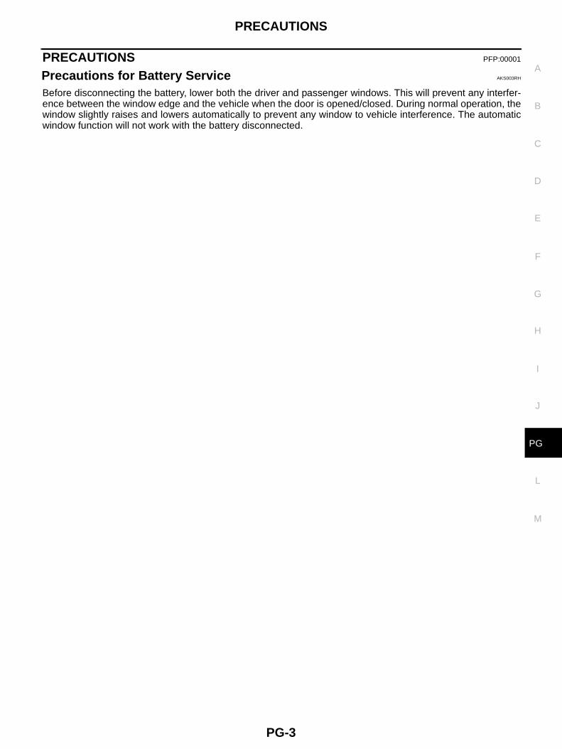
PRECAUTIONS PFP:00001
Precautions for Battery Service AKS003RH
Before disconnecting the battery, lower both the driver and passenger windows. This will prevent any interfer-ence between the window edge and the vehicle when the door is opened/closed. During normal operation, thewindow slightly raises and lowers automatically to prevent any window to vehicle interference. The automaticwindow function will not work with the battery disconnected.
PG-4
POWER SUPPLY ROUTING CIRCUIT
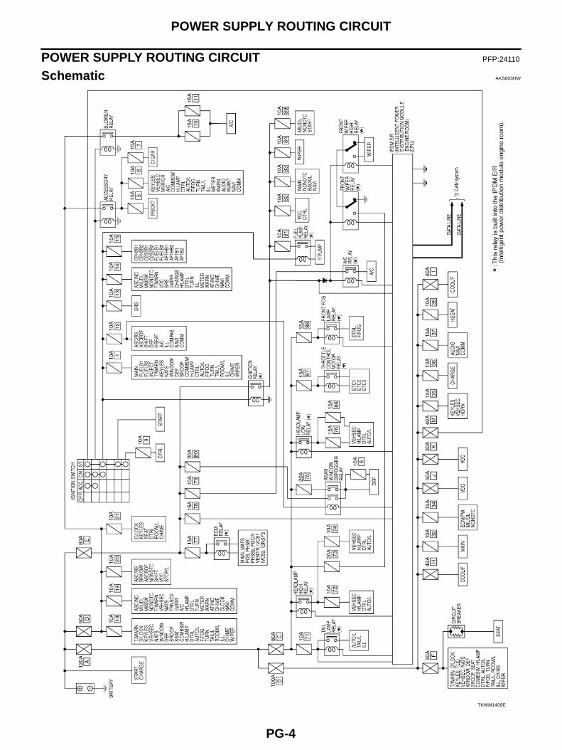
POWER SUPPLY ROUTING CIRCUIT PFP:24110
Schematic AKS003HW
TKWM1409E
POWER SUPPLY ROUTING CIRCUIT
PG-5
C
D
E
F
G
H
I
J
L
M
A
B
PG
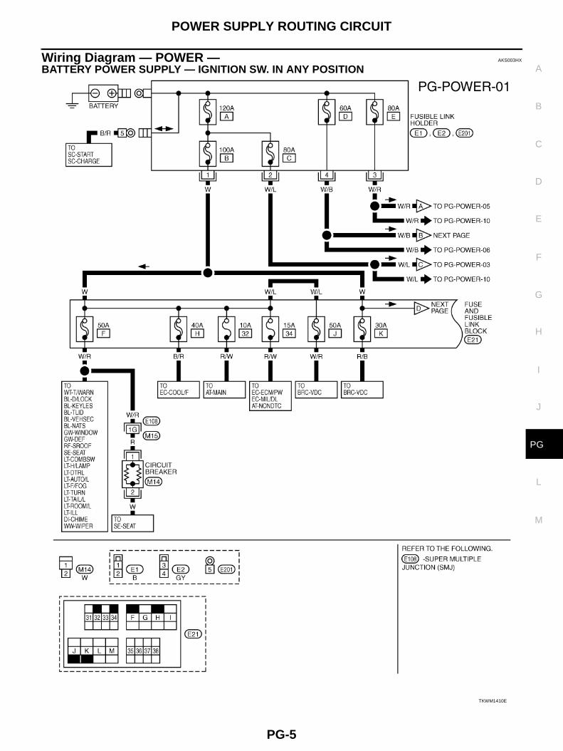
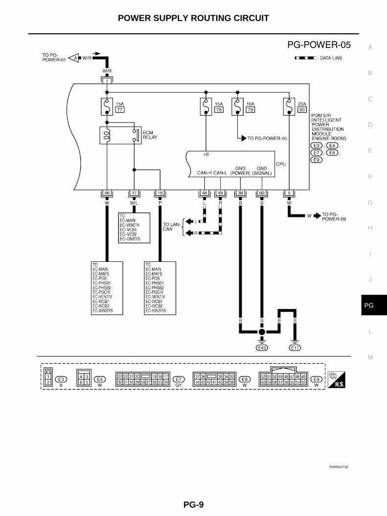
Wiring Diagram — POWER — AKS003HX
BATTERY POWER SUPPLY — IGNITION SW. IN ANY POSITION
TKWM1410E
PG-6
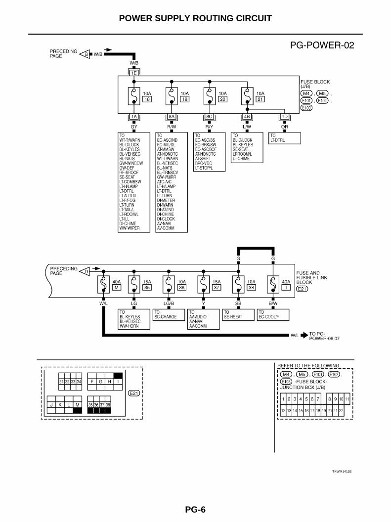
POWER SUPPLY ROUTING CIRCUIT
TKWM1411E
POWER SUPPLY ROUTING CIRCUIT
PG-7
C
D
E
F
G
H
I
J
L
M
A
B
PG
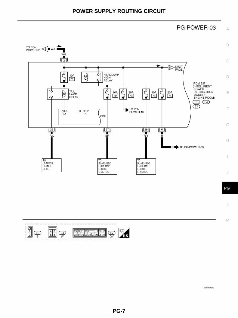
TKWM0937E
PG-8
POWER SUPPLY ROUTING CIRCUIT
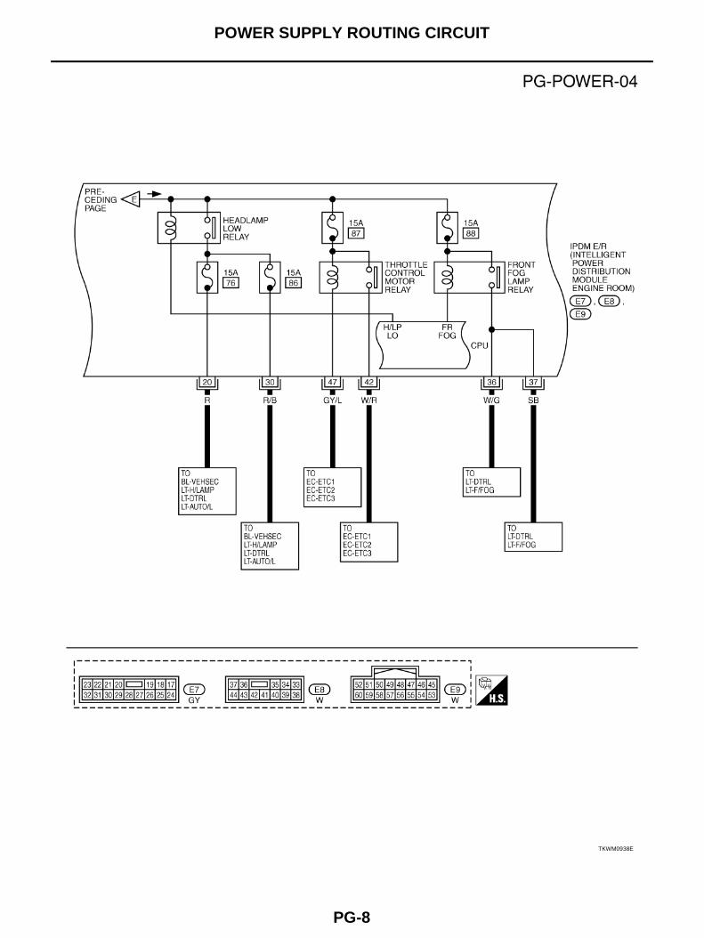
TKWM0938E
POWER SUPPLY ROUTING CIRCUIT
PG-9
C
D
E
F
G
H
I
J
L
M
A
B
PG
TKWM1071E
PG-10
POWER SUPPLY ROUTING CIRCUIT
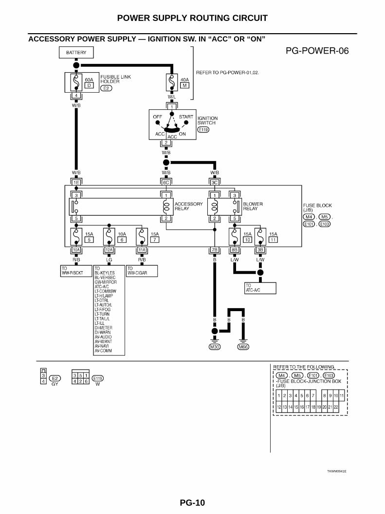
ACCESSORY POWER SUPPLY — IGNITION SW. IN “ACC” OR “ON”
TKWM0941E
POWER SUPPLY ROUTING CIRCUIT
PG-11
C
D
E
F
G
H
I
J
L
M
A
B
PG
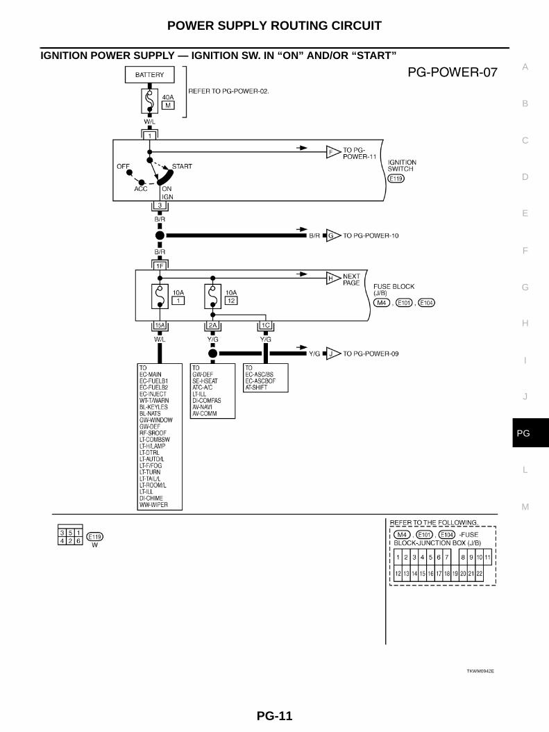
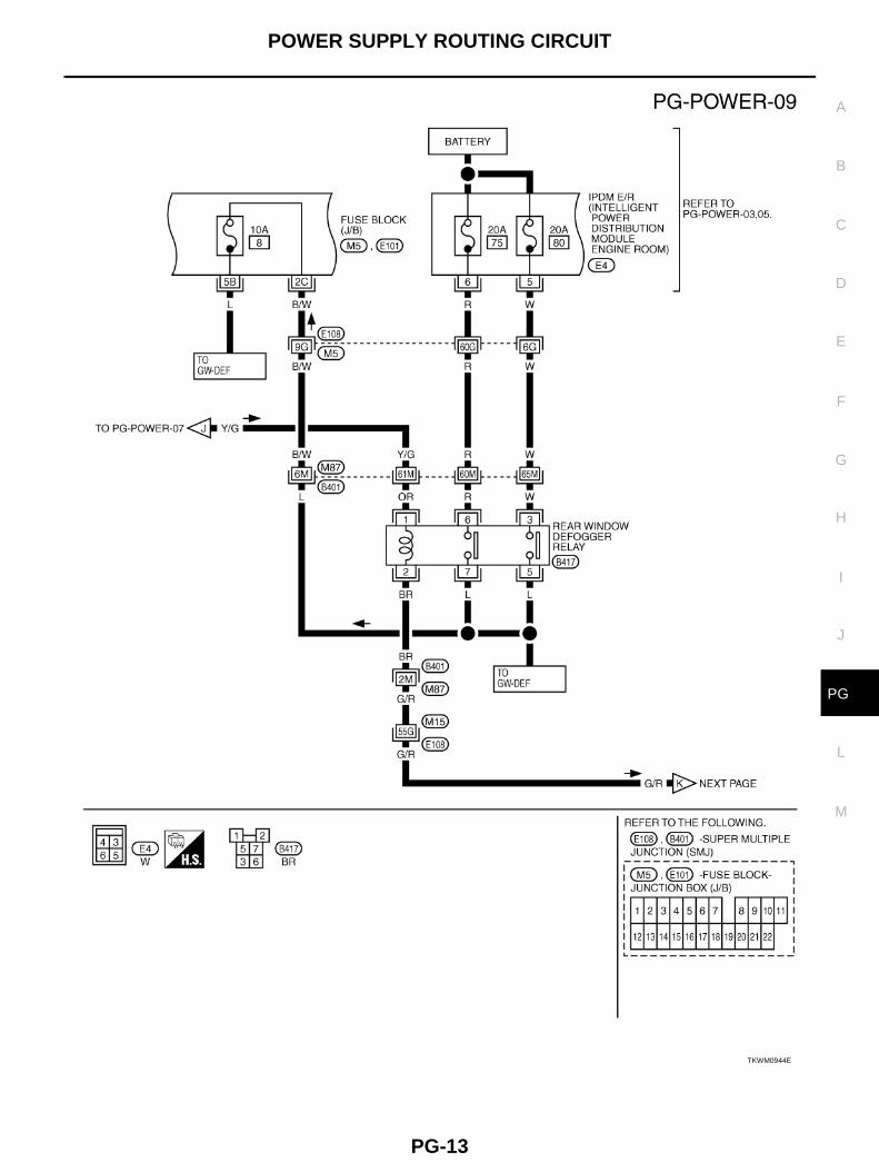
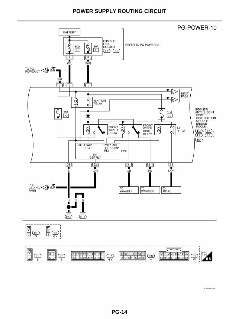
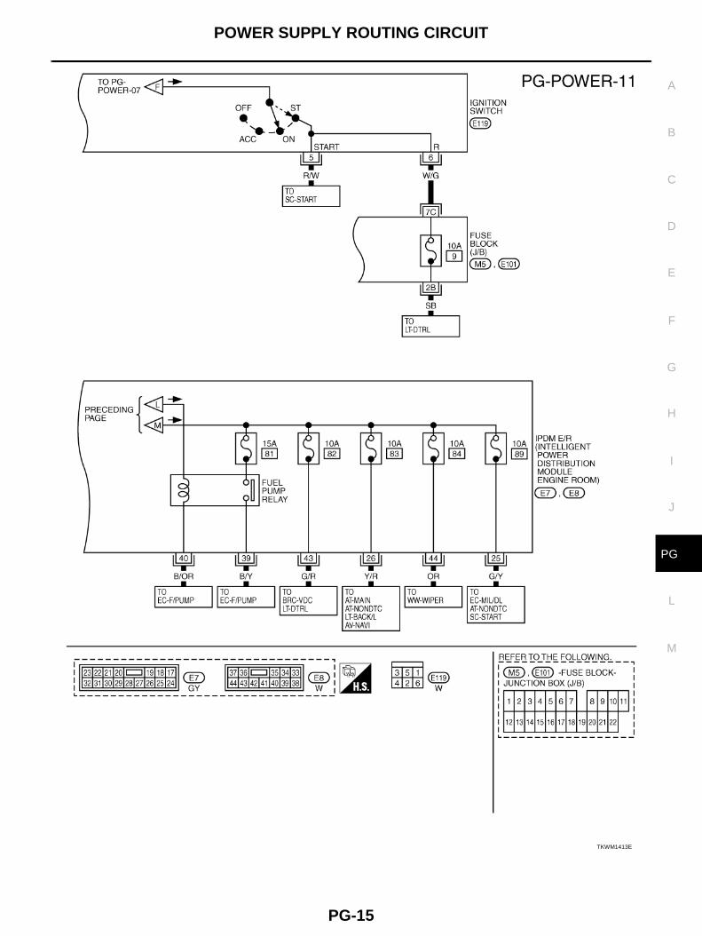
IGNITION POWER SUPPLY — IGNITION SW. IN “ON” AND/OR “START”
TKWM0942E
PG-12
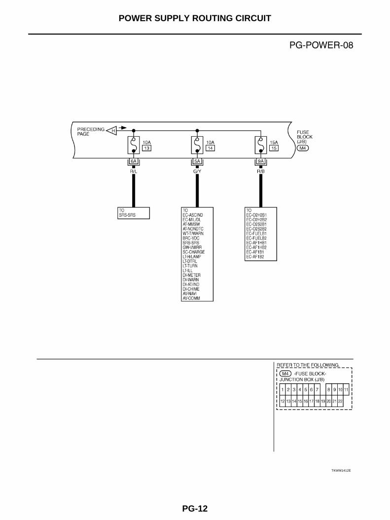
POWER SUPPLY ROUTING CIRCUIT
TKWM1412E
POWER SUPPLY ROUTING CIRCUIT
PG-13
C
D
E
F
G
H
I
J
L
M
A
B
PG
TKWM0944E
PG-14
POWER SUPPLY ROUTING CIRCUIT
TKWM0945E
POWER SUPPLY ROUTING CIRCUIT
PG-15
C
D
E
F
G
H
I
J
L
M
A
B
PG
TKWM1413E
PG-16
POWER SUPPLY ROUTING CIRCUIT
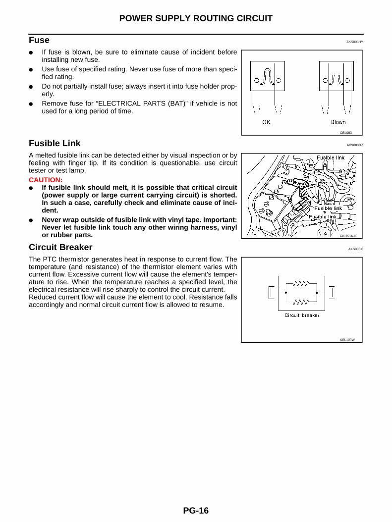
Fuse AKS003HY
● If fuse is blown, be sure to eliminate cause of incident beforeinstalling new fuse.
● Use fuse of specified rating. Never use fuse of more than speci-fied rating.
● Do not partially install fuse; always insert it into fuse holder prop-erly.
● Remove fuse for “ELECTRICAL PARTS (BAT)” if vehicle is notused for a long period of time.
Fusible Link AKS003HZ
A melted fusible link can be detected either by visual inspection or byfeeling with finger tip. If its condition is questionable, use circuittester or test lamp.CAUTION:● If fusible link should melt, it is possible that critical circuit
(power supply or large current carrying circuit) is shorted.In such a case, carefully check and eliminate cause of inci-dent.
● Never wrap outside of fusible link with vinyl tape. Important:Never let fusible link touch any other wiring harness, vinylor rubber parts.
Circuit Breaker AKS003I0
The PTC thermistor generates heat in response to current flow. Thetemperature (and resistance) of the thermistor element varies withcurrent flow. Excessive current flow will cause the element's temper-ature to rise. When the temperature reaches a specified level, theelectrical resistance will rise sharply to control the circuit current.Reduced current flow will cause the element to cool. Resistance fallsaccordingly and normal circuit current flow is allowed to resume.
CEL083
CKIT0163E
SEL109W
IPDM E/R (INTELLIGENT POWER DISTRIBUTION MODULE ENGINE ROOM)
PG-17
C
D
E
F
G
H
I
J
L
M
A
B
PG
IPDM E/R (INTELLIGENT POWER DISTRIBUTION MODULE ENGINE ROOM)PFP:284B7
System Description AKS00A37
● IPDM E/R (Intelligent Power Distribution Module Engine Room) integrates the relay box and fuse blockwhich were originally placed in engine compartment. It controls integrated relay via IPDM E/R control cir-cuit.
● IPDM E/R-integrated control circuit performs ON-OFF operation of relay, CAN communication control, oilpressure switch signal reception, etc.
● It controls operation of each electrical part via ECM, BCM and CAN communication lines.CAUTION:None of the IPDM E/R-integrated relays can be removed.
SYSTEMS CONTROLLED BY IPDM E/R1. Lamp control
Using CAN communication line, it receives signal from BCM and controls the following lamps:– Head lamps (Hi, Lo)– Parking lamps– Tail lamps– Front fog lamps2. Wiper control
Using CAN communication line, it receives signals from BCM and controls the front wipers.3. Rear window defogger relay control
Using CAN communication line, it receives signals from BCM and controls the rear window defoggerrelay.
4. A/C compressor controlUsing CAN communication line, it receives signals from ECM and controls the A/C relay.
5. Cooling fan controlUsing CAN communication line, it receives signals from ECM and controls cooling fan relay.
6. Horn controlUsing CAN communication line, it receives signals from BCM and controls horn relay.
CAN COMMUNICATION LINE CONTROLWith CAN communication, by connecting each control unit using two communication lines (CAN L-line, CANH-line), it is possible to transmit maximum amount of information with minimum wiring. Each control unit cantransmit and receive data, and reads necessary information only.1. Fail-safe control
● When CAN communication with other control units is impossible, IPDM E/R performs fail-safe control.After CAN communication recovers normally, it also returns to normal control.
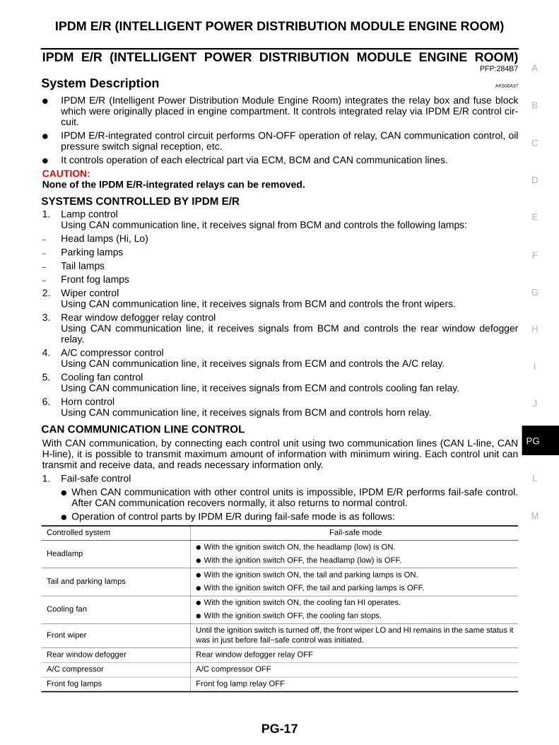
● Operation of control parts by IPDM E/R during fail-safe mode is as follows:
Controlled system Fail-safe mode
Headlamp● With the ignition switch ON, the headlamp (low) is ON.
● With the ignition switch OFF, the headlamp (low) is OFF.
Tail and parking lamps● With the ignition switch ON, the tail and parking lamps is ON.
● With the ignition switch OFF, the tail and parking lamps is OFF.
Cooling fan● With the ignition switch ON, the cooling fan HI operates.
● With the ignition switch OFF, the cooling fan stops.
Front wiperUntil the ignition switch is turned off, the front wiper LO and HI remains in the same status it was in just before fail−safe control was initiated.
Rear window defogger Rear window defogger relay OFF
A/C compressor A/C compressor OFF
Front fog lamps Front fog lamp relay OFF
PG-18
IPDM E/R (INTELLIGENT POWER DISTRIBUTION MODULE ENGINE ROOM)
IPDM E/R STATUS CONTROLIn order to save power, IPDM E/R switches status by itself based on each operating condition.1. CAN communication status
● CAN communication is normally performed with other control units.● Individual unit control by IPDM E/R is normally performed.● When sleep request signal is received from BCM, mode is switched to sleep waiting status.
2. Sleep waiting status● Process to stop CAN communication is activated.● All systems controlled by IPDM E/R are stopped. When 1 seconds have elapsed after CAN communi-
cation with other control units is stopped, mode switches to sleep status.3. Sleep status
● IPDM E/R operates in low current-consumption mode.● CAN communication is stopped.● When a change in CAN communication line is detected, mode switches to CAN communication status.● When a change hood switch or ignition switch signal is detected, mode switches to CAN communica-
tion status.
CAN Communication System Description AKS00A38
CAN (Controller Area Network) is a serial communication line for real time application. It is an on-vehicle mul-tiplex communication line with high data communication speed and excellent error detection ability. Modernvehicles are equipped with many electronic control units and each control unit shares information and linkswith other control units during operation (not independent). In CAN communication, control units are con-nected with 2 communication lines (CAN H line, CAN L line) allowing a high rate of information transmissionwith less wiring. Each control unit transmits/receives data but selectively reads required data only.
CAN Communication Unit AKS00A39
Refer to LAN-4, "CAN Communication Unit" .
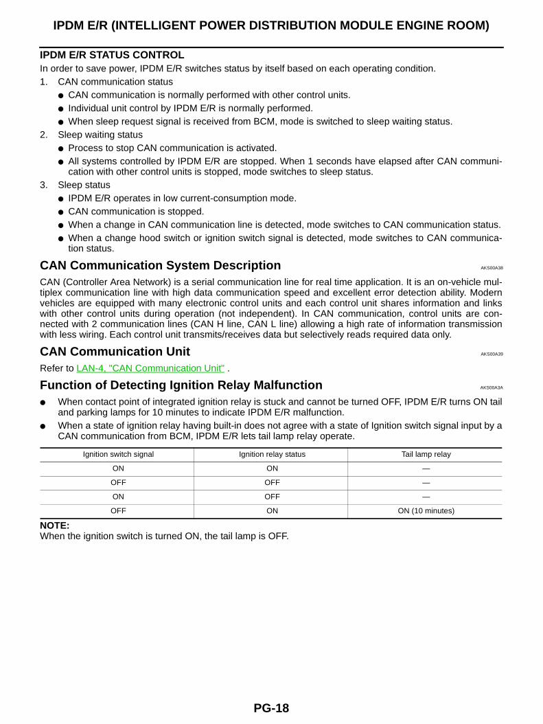
Function of Detecting Ignition Relay Malfunction AKS00A3A
● When contact point of integrated ignition relay is stuck and cannot be turned OFF, IPDM E/R turns ON tailand parking lamps for 10 minutes to indicate IPDM E/R malfunction.
● When a state of ignition relay having built-in does not agree with a state of Ignition switch signal input by aCAN communication from BCM, IPDM E/R lets tail lamp relay operate.
NOTE:When the ignition switch is turned ON, the tail lamp is OFF.
Ignition switch signal Ignition relay status Tail lamp relay
ON ON —
OFF OFF —
ON OFF —
OFF ON ON (10 minutes)
IPDM E/R (INTELLIGENT POWER DISTRIBUTION MODULE ENGINE ROOM)
PG-19
C
D
E
F
G
H
I
J
L
M
A
B
PG
CONSULT-II AKS00A3B
CONSULT-II performs the following functions with combination of data receiving, command and transmissionusing the CAN communication line from the IPDM E/R.
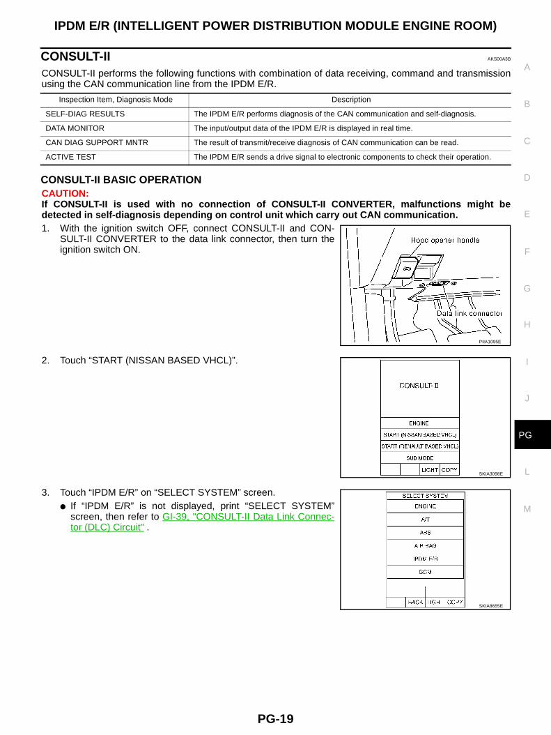
CONSULT-II BASIC OPERATIONCAUTION:If CONSULT-II is used with no connection of CONSULT-II CONVERTER, malfunctions might bedetected in self-diagnosis depending on control unit which carry out CAN communication.1. With the ignition switch OFF, connect CONSULT-II and CON-
SULT-II CONVERTER to the data link connector, then turn theignition switch ON.
2. Touch “START (NISSAN BASED VHCL)”.
3. Touch “IPDM E/R” on “SELECT SYSTEM” screen.● If “IPDM E/R” is not displayed, print “SELECT SYSTEM”
screen, then refer to GI-39, "CONSULT-II Data Link Connec-tor (DLC) Circuit" .
Inspection Item, Diagnosis Mode Description
SELF-DIAG RESULTS The IPDM E/R performs diagnosis of the CAN communication and self-diagnosis.
DATA MONITOR The input/output data of the IPDM E/R is displayed in real time.
CAN DIAG SUPPORT MNTR The result of transmit/receive diagnosis of CAN communication can be read.
ACTIVE TEST The IPDM E/R sends a drive signal to electronic components to check their operation.
PIIA1095E
SKIA3098E
SKIA8655E
PG-20
IPDM E/R (INTELLIGENT POWER DISTRIBUTION MODULE ENGINE ROOM)
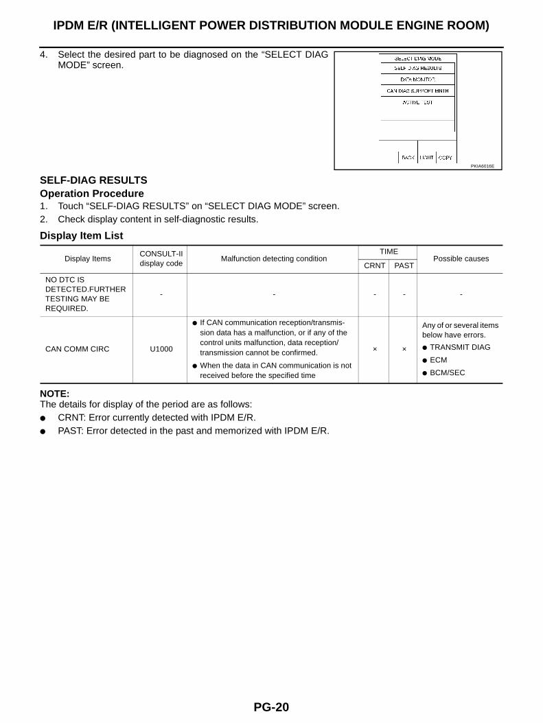
4. Select the desired part to be diagnosed on the “SELECT DIAGMODE” screen.
SELF-DIAG RESULTSOperation Procedure1. Touch “SELF-DIAG RESULTS” on “SELECT DIAG MODE” screen.2. Check display content in self-diagnostic results.
Display Item List
NOTE:The details for display of the period are as follows:● CRNT: Error currently detected with IPDM E/R.● PAST: Error detected in the past and memorized with IPDM E/R.
PKIA6016E
Display ItemsCONSULT-II display code
Malfunction detecting conditionTIME
Possible causesCRNT PAST
NO DTC IS DETECTED.FURTHER TESTING MAY BE REQUIRED.
- - - - -
CAN COMM CIRC U1000
● If CAN communication reception/transmis-sion data has a malfunction, or if any of the control units malfunction, data reception/transmission cannot be confirmed.
● When the data in CAN communication is not received before the specified time
× ×
Any of or several items below have errors.
● TRANSMIT DIAG
● ECM
● BCM/SEC
IPDM E/R (INTELLIGENT POWER DISTRIBUTION MODULE ENGINE ROOM)
PG-21
C
D
E
F
G
H
I
J
L
M
A
B
PG
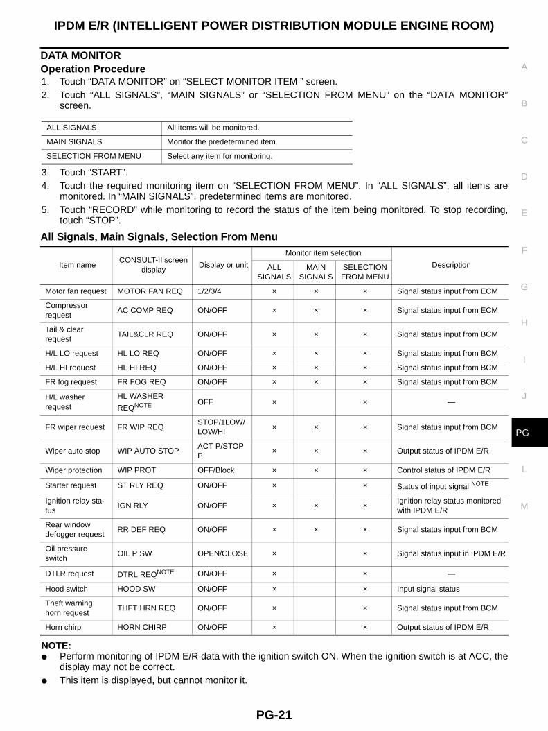
DATA MONITOROperation Procedure1. Touch “DATA MONITOR” on “SELECT MONITOR ITEM ” screen.2. Touch “ALL SIGNALS”, “MAIN SIGNALS” or “SELECTION FROM MENU” on the “DATA MONITOR”
screen.
3. Touch “START”.4. Touch the required monitoring item on “SELECTION FROM MENU”. In “ALL SIGNALS”, all items are
monitored. In “MAIN SIGNALS”, predetermined items are monitored.5. Touch “RECORD” while monitoring to record the status of the item being monitored. To stop recording,
touch “STOP”.
All Signals, Main Signals, Selection From Menu
NOTE:● Perform monitoring of IPDM E/R data with the ignition switch ON. When the ignition switch is at ACC, the
display may not be correct.● This item is displayed, but cannot monitor it.
ALL SIGNALS All items will be monitored.
MAIN SIGNALS Monitor the predetermined item.
SELECTION FROM MENU Select any item for monitoring.
Item nameCONSULT-II screen
displayDisplay or unit
Monitor item selection
DescriptionALLSIGNALS
MAIN SIGNALS
SELECTION FROM MENU
Motor fan request MOTOR FAN REQ 1/2/3/4 × × × Signal status input from ECM
Compressor request
AC COMP REQ ON/OFF × × × Signal status input from ECM
Tail & clear request
TAIL&CLR REQ ON/OFF × × × Signal status input from BCM
H/L LO request HL LO REQ ON/OFF × × × Signal status input from BCM
H/L HI request HL HI REQ ON/OFF × × × Signal status input from BCM
FR fog request FR FOG REQ ON/OFF × × × Signal status input from BCM
H/L washer request
HL WASHER
REQNOTE OFF × × —
FR wiper request FR WIP REQSTOP/1LOW/LOW/HI
× × × Signal status input from BCM
Wiper auto stop WIP AUTO STOPACT P/STOP P
× × × Output status of IPDM E/R
Wiper protection WIP PROT OFF/Block × × × Control status of IPDM E/R
Starter request ST RLY REQ ON/OFF × × Status of input signal NOTE
Ignition relay sta-tus
IGN RLY ON/OFF × × × Ignition relay status monitored with IPDM E/R
Rear window defogger request
RR DEF REQ ON/OFF × × × Signal status input from BCM
Oil pressure switch
OIL P SW OPEN/CLOSE × × Signal status input in IPDM E/R
DTLR request DTRL REQNOTE ON/OFF × × —
Hood switch HOOD SW ON/OFF × × Input signal status
Theft warning horn request
THFT HRN REQ ON/OFF × × Signal status input from BCM
Horn chirp HORN CHIRP ON/OFF × × Output status of IPDM E/R
PG-22
IPDM E/R (INTELLIGENT POWER DISTRIBUTION MODULE ENGINE ROOM)
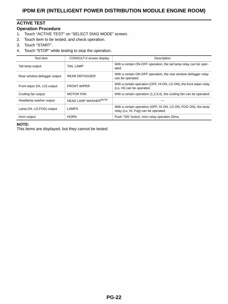
ACTIVE TESTOperation Procedure1. Touch “ACTIVE TEST” on “SELECT DIAG MODE” screen.2. Touch item to be tested, and check operation.3. Touch “START”.4. Touch “STOP” while testing to stop the operation.
NOTE:This items are displayed, but they cannot be tested.
Test item CONSULT-II screen display Description
Tail lamp output TAIL LAMPWith a certain ON-OFF operation, the tail lamp relay can be oper-ated.
Rear window defogger output REAR DEFOGGERWith a certain ON-OFF operation, the rear window defogger relay can be operated.
Front wiper (HI, LO) output FRONT WIPERWith a certain operation (OFF, HI ON, LO ON), the front wiper relay (Lo, Hi) can be operated.
Cooling fan output MOTOR FAN With a certain operation (1,2,3,4), the cooling fan can be operated.
Headlamp washer output HEAD LANP WASHERNOTE —
Lamp (HI, LO,FOG) output LAMPSWith a certain operation (OFF, HI ON, LO ON, FOG ON), the lamp relay (Lo, Hi, Fog) can be operated.
Horn output HORN Push "ON" button, horn relay operates 20ms.
IPDM E/R (INTELLIGENT POWER DISTRIBUTION MODULE ENGINE ROOM)
PG-23
C
D
E
F
G
H
I
J
L
M
A
B
PG
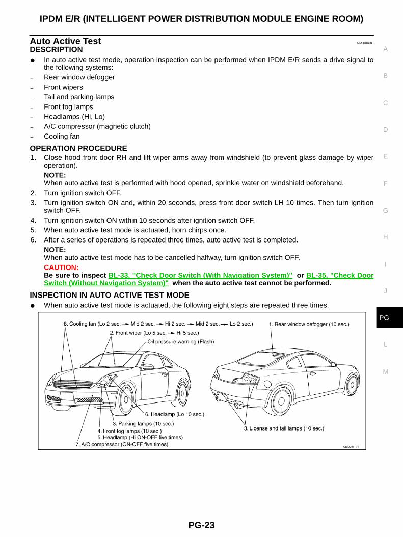
Auto Active Test AKS00A3C
DESCRIPTION● In auto active test mode, operation inspection can be performed when IPDM E/R sends a drive signal to
the following systems:– Rear window defogger– Front wipers– Tail and parking lamps– Front fog lamps– Headlamps (Hi, Lo)– A/C compressor (magnetic clutch)– Cooling fan
OPERATION PROCEDURE1. Close hood front door RH and lift wiper arms away from windshield (to prevent glass damage by wiper
operation).NOTE:When auto active test is performed with hood opened, sprinkle water on windshield beforehand.
2. Turn ignition switch OFF.3. Turn ignition switch ON and, within 20 seconds, press front door switch LH 10 times. Then turn ignition
switch OFF.4. Turn ignition switch ON within 10 seconds after ignition switch OFF. 5. When auto active test mode is actuated, horn chirps once.6. After a series of operations is repeated three times, auto active test is completed.
NOTE:When auto active test mode has to be cancelled halfway, turn ignition switch OFF.CAUTION:Be sure to inspect BL-33, "Check Door Switch (With Navigation System)" or BL-35, "Check DoorSwitch (Without Navigation System)" when the auto active test cannot be performed.
INSPECTION IN AUTO ACTIVE TEST MODE● When auto active test mode is actuated, the following eight steps are repeated three times.
SKIA9133E
PG-24
IPDM E/R (INTELLIGENT POWER DISTRIBUTION MODULE ENGINE ROOM)
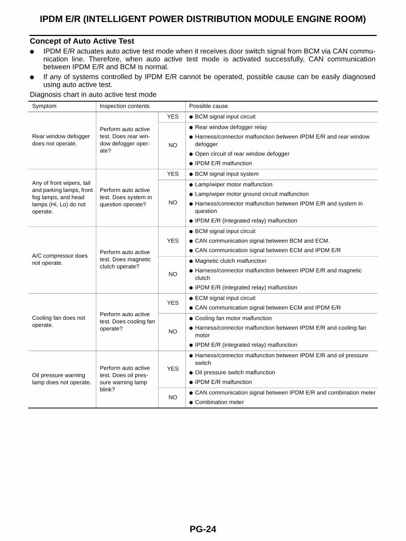
Concept of Auto Active Test● IPDM E/R actuates auto active test mode when it receives door switch signal from BCM via CAN commu-
nication line. Therefore, when auto active test mode is activated successfully, CAN communicationbetween IPDM E/R and BCM is normal.
● If any of systems controlled by IPDM E/R cannot be operated, possible cause can be easily diagnosedusing auto active test.
Diagnosis chart in auto active test mode
Symptom Inspection contents Possible cause
Rear window defogger does not operate.
Perform auto active test. Does rear win-dow defogger oper-ate?
YES ● BCM signal input circuit
NO
● Rear window defogger relay
● Harness/connector malfunction between IPDM E/R and rear window defogger
● Open circuit of rear window defogger
● IPDM E/R malfunction
Any of front wipers, tail and parking lamps, front fog lamps, and head lamps (Hi, Lo) do not operate.
Perform auto active test. Does system in question operate?
YES ● BCM signal input system
NO
● Lamp/wiper motor malfunction
● Lamp/wiper motor ground circuit malfunction
● Harness/connector malfunction between IPDM E/R and system in question
● IPDM E/R (integrated relay) malfunction
A/C compressor does not operate.
Perform auto active test. Does magnetic clutch operate?
YES
● BCM signal input circuit
● CAN communication signal between BCM and ECM.
● CAN communication signal between ECM and IPDM E/R
NO
● Magnetic clutch malfunction
● Harness/connector malfunction between IPDM E/R and magnetic clutch
● IPDM E/R (integrated relay) malfunction
Cooling fan does not operate.
Perform auto active test. Does cooling fan operate?
YES● ECM signal input circuit
● CAN communication signal between ECM and IPDM E/R
NO
● Cooling fan motor malfunction
● Harness/connector malfunction between IPDM E/R and cooling fan motor
● IPDM E/R (integrated relay) malfunction
Oil pressure warning lamp does not operate.
Perform auto active test. Does oil pres-sure warning lamp blink?
YES
● Harness/connector malfunction between IPDM E/R and oil pressure switch
● Oil pressure switch malfunction
● IPDM E/R malfunction
NO● CAN communication signal between IPDM E/R and combination meter
● Combination meter
IPDM E/R (INTELLIGENT POWER DISTRIBUTION MODULE ENGINE ROOM)
PG-25
C
D
E
F
G
H
I
J
L
M
A
B
PG
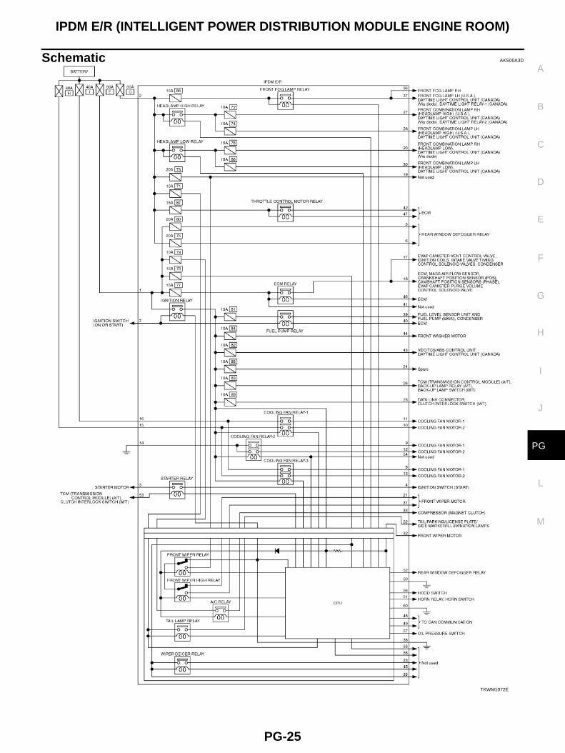
Schematic AKS00A3D
TKWM1072E
PG-26
IPDM E/R (INTELLIGENT POWER DISTRIBUTION MODULE ENGINE ROOM)
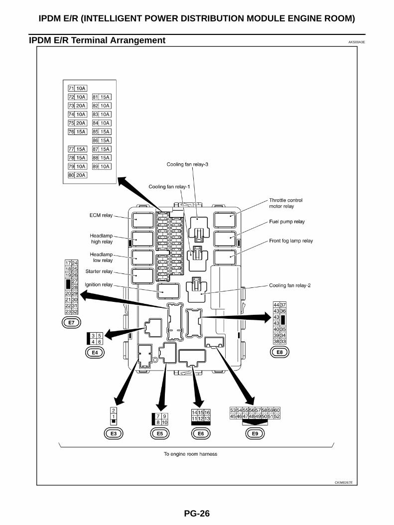
IPDM E/R Terminal Arrangement AKS00A3E
CKIM0267E
IPDM E/R (INTELLIGENT POWER DISTRIBUTION MODULE ENGINE ROOM)
PG-27
C
D
E
F
G
H
I
J
L
M
A
B
PG
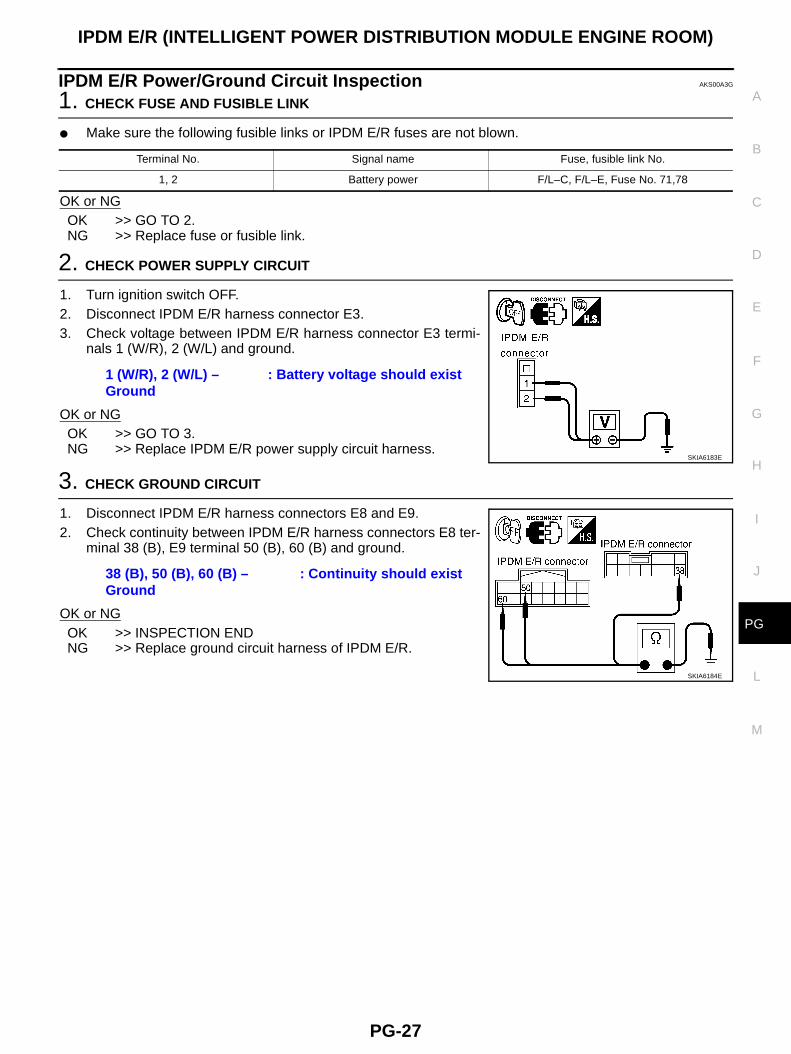
IPDM E/R Power/Ground Circuit Inspection AKS00A3G
1. CHECK FUSE AND FUSIBLE LINK
● Make sure the following fusible links or IPDM E/R fuses are not blown.
OK or NGOK >> GO TO 2.NG >> Replace fuse or fusible link.
2. CHECK POWER SUPPLY CIRCUIT
1. Turn ignition switch OFF.2. Disconnect IPDM E/R harness connector E3.3. Check voltage between IPDM E/R harness connector E3 termi-
nals 1 (W/R), 2 (W/L) and ground.
OK or NGOK >> GO TO 3.NG >> Replace IPDM E/R power supply circuit harness.
3. CHECK GROUND CIRCUIT
1. Disconnect IPDM E/R harness connectors E8 and E9.2. Check continuity between IPDM E/R harness connectors E8 ter-
minal 38 (B), E9 terminal 50 (B), 60 (B) and ground.
OK or NGOK >> INSPECTION ENDNG >> Replace ground circuit harness of IPDM E/R.
Terminal No. Signal name Fuse, fusible link No.
1, 2 Battery power F/L–C, F/L–E, Fuse No. 71,78
1 (W/R), 2 (W/L) – Ground
: Battery voltage should exist
SKIA6183E
38 (B), 50 (B), 60 (B) – Ground
: Continuity should exist
SKIA6184E
PG-28
IPDM E/R (INTELLIGENT POWER DISTRIBUTION MODULE ENGINE ROOM)
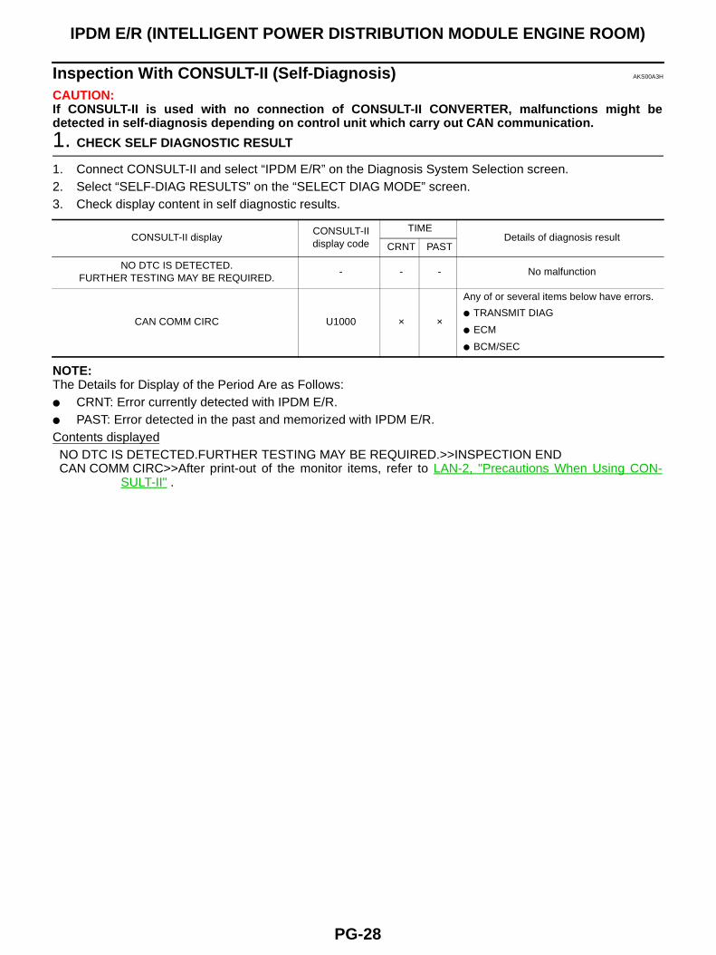
Inspection With CONSULT-II (Self-Diagnosis) AKS00A3H
CAUTION:If CONSULT-II is used with no connection of CONSULT-II CONVERTER, malfunctions might bedetected in self-diagnosis depending on control unit which carry out CAN communication.
1. CHECK SELF DIAGNOSTIC RESULT
1. Connect CONSULT-II and select “IPDM E/R” on the Diagnosis System Selection screen.2. Select “SELF-DIAG RESULTS” on the “SELECT DIAG MODE” screen.3. Check display content in self diagnostic results.
NOTE:The Details for Display of the Period Are as Follows:● CRNT: Error currently detected with IPDM E/R.● PAST: Error detected in the past and memorized with IPDM E/R.Contents displayedNO DTC IS DETECTED.FURTHER TESTING MAY BE REQUIRED.>>INSPECTION ENDCAN COMM CIRC>>After print-out of the monitor items, refer to LAN-2, "Precautions When Using CON-
SULT-II" .
CONSULT-II displayCONSULT-II display code
TIMEDetails of diagnosis result
CRNT PAST
NO DTC IS DETECTED.FURTHER TESTING MAY BE REQUIRED.
- - - No malfunction
CAN COMM CIRC U1000 × ×
Any of or several items below have errors.
● TRANSMIT DIAG
● ECM
● BCM/SEC
IPDM E/R (INTELLIGENT POWER DISTRIBUTION MODULE ENGINE ROOM)
PG-29
C
D
E
F
G
H
I
J
L
M
A
B
PG
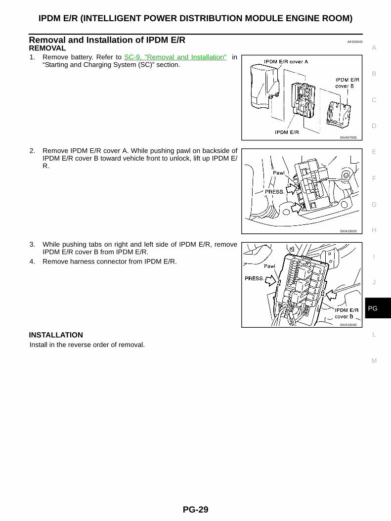
Removal and Installation of IPDM E/R AKS00A3I
REMOVAL1. Remove battery. Refer to SC-9, "Removal and Installation" in
“Starting and Charging System (SC)” section.
2. Remove IPDM E/R cover A. While pushing pawl on backside ofIPDM E/R cover B toward vehicle front to unlock, lift up IPDM E/R.
3. While pushing tabs on right and left side of IPDM E/R, removeIPDM E/R cover B from IPDM E/R.
4. Remove harness connector from IPDM E/R.
INSTALLATIONInstall in the reverse order of removal.
SKIA0793E
SKIA1902E
SKIA1904E
PG-30
GROUND
GROUND PFP:00011
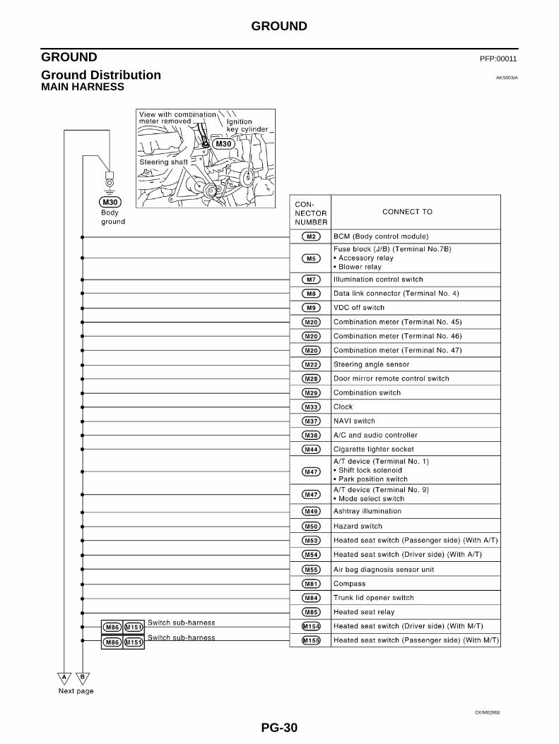
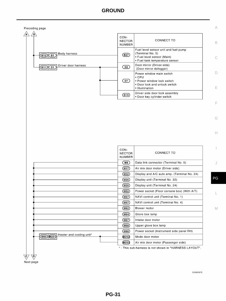
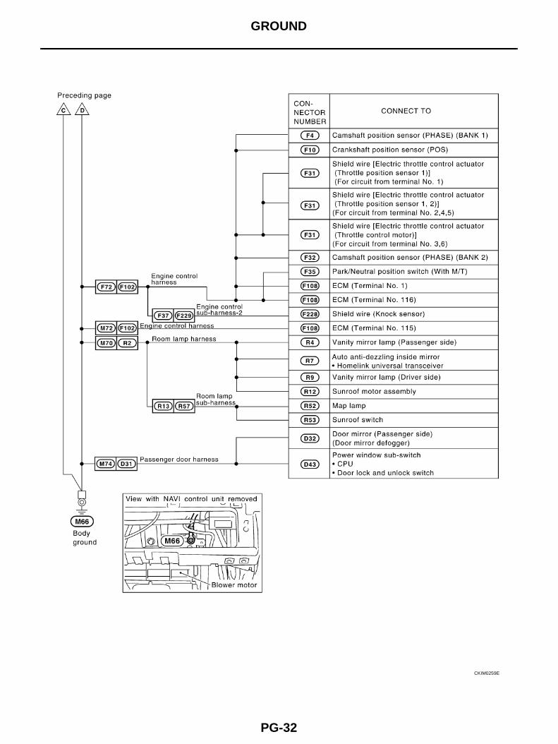
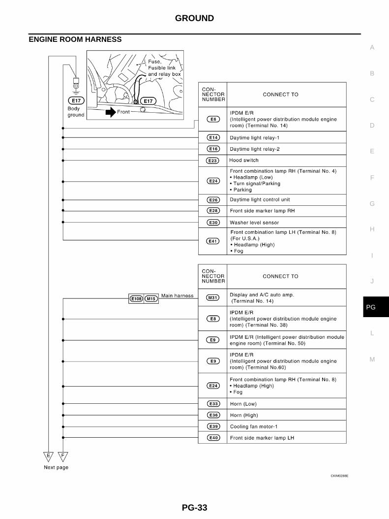
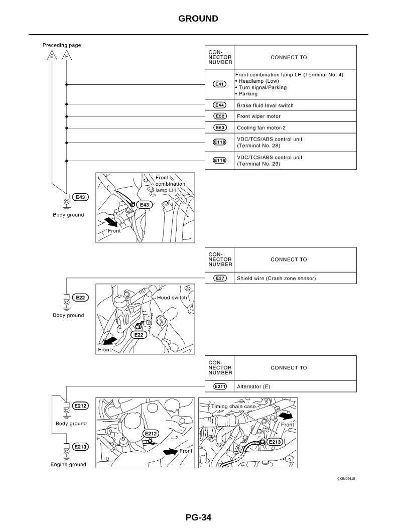
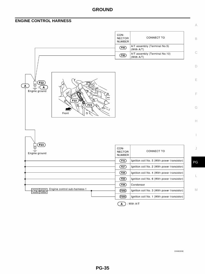
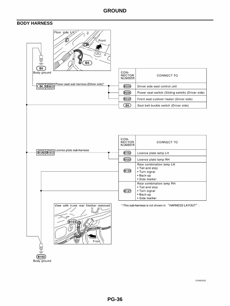
Ground Distribution AKS003IA
MAIN HARNESS
CKIM0286E
GROUND
PG-31
C
D
E
F
G
H
I
J
L
M
A
B
PG
CKIM0287E
PG-32
GROUND
CKIM0259E
GROUND
PG-33
C
D
E
F
G
H
I
J
L
M
A
B
PG
ENGINE ROOM HARNESS
CKIM0288E
PG-34
GROUND
CKIM0261E
GROUND
PG-35
C
D
E
F
G
H
I
J
L
M
A
B
PG
ENGINE CONTROL HARNESS
CKIM0283E
PG-36
GROUND
BODY HARNESS
CKIM0262E
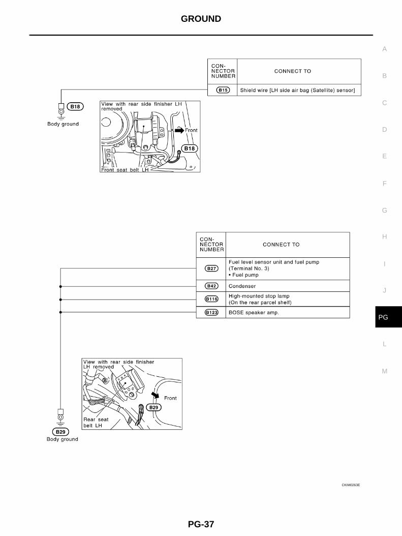
GROUND
PG-37
C
D
E
F
G
H
I
J
L
M
A
B
PG
CKIM0263E
PG-38
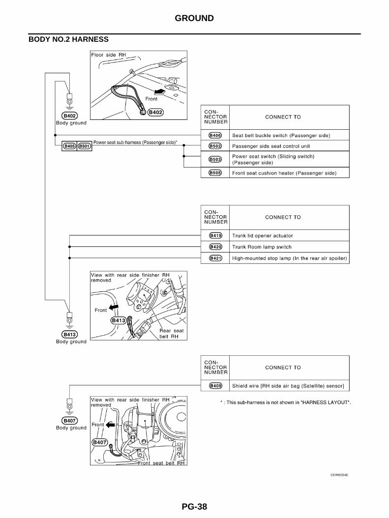
GROUND
BODY NO.2 HARNESS
CKIM0264E
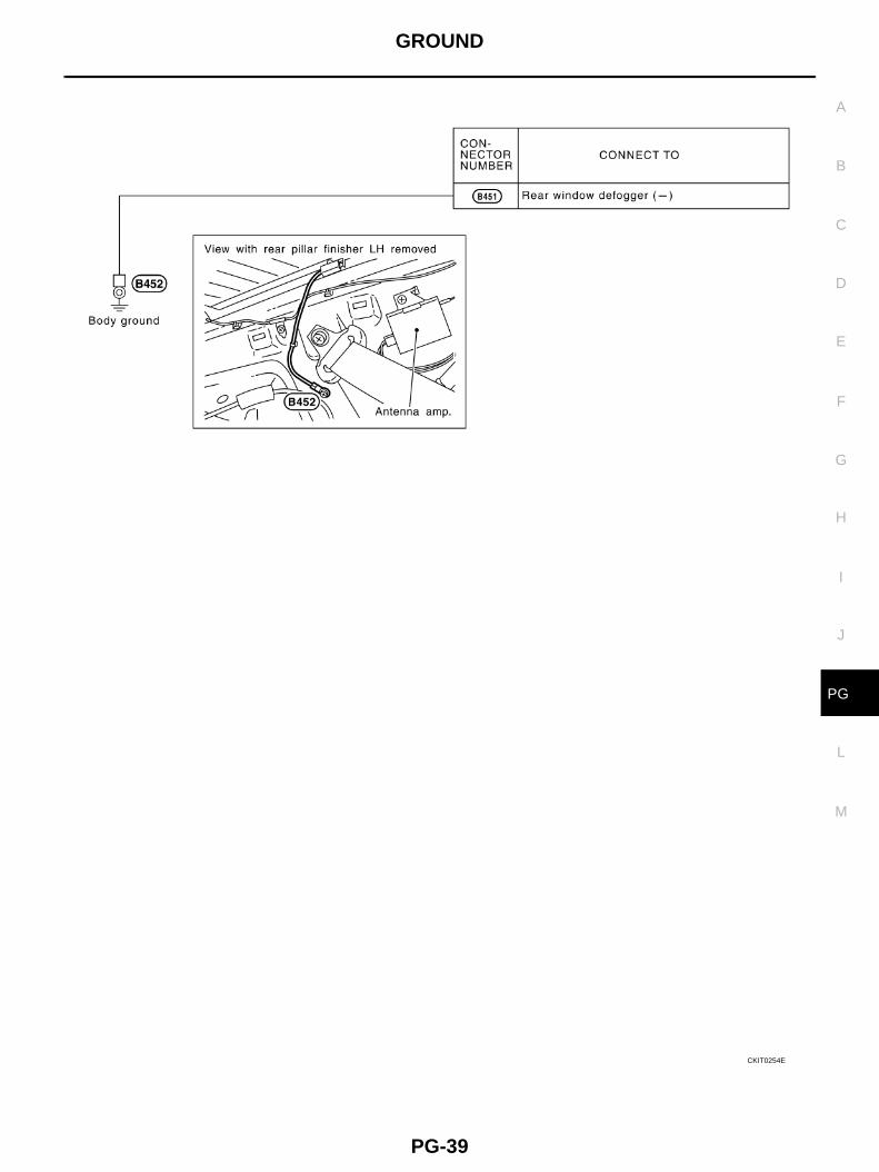
GROUND
PG-39
C
D
E
F
G
H
I
J
L
M
A
B
PG
CKIT0254E
PG-40
HARNESS
HARNESS PFP:00011
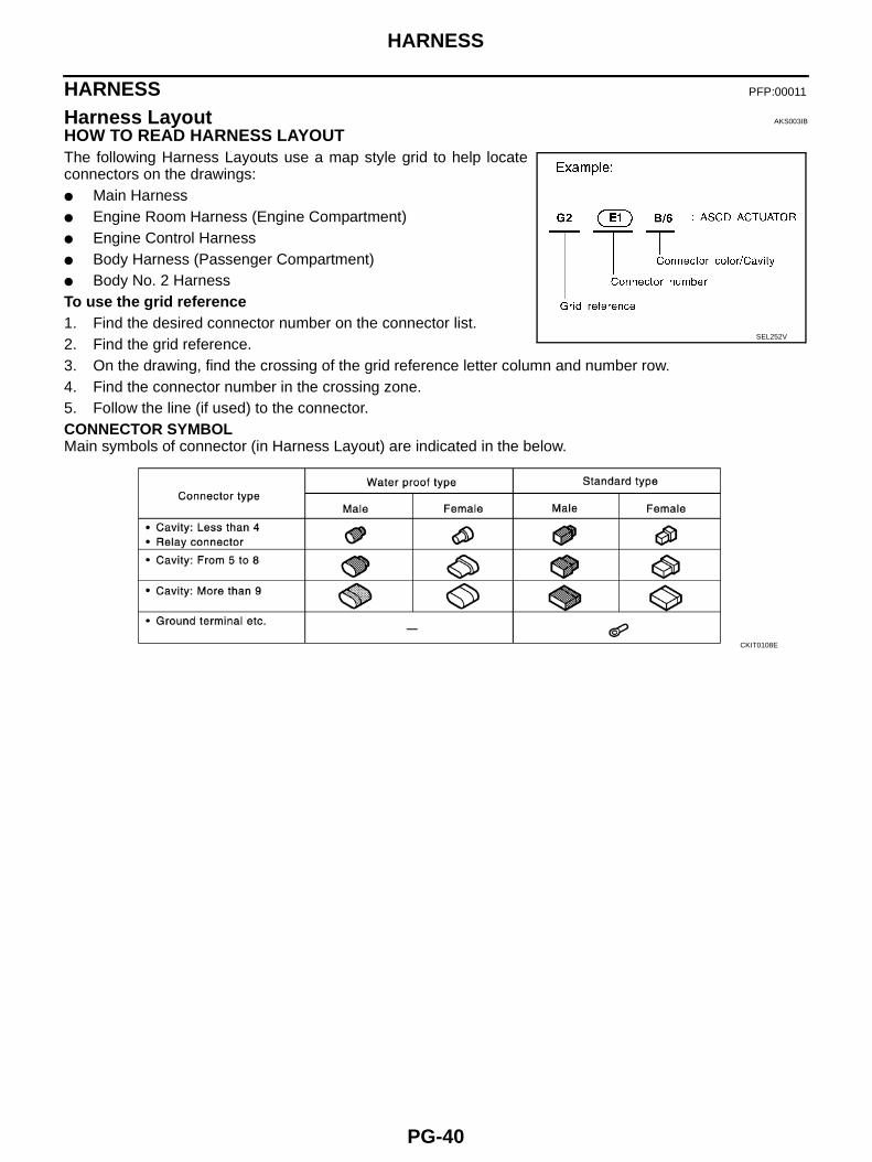
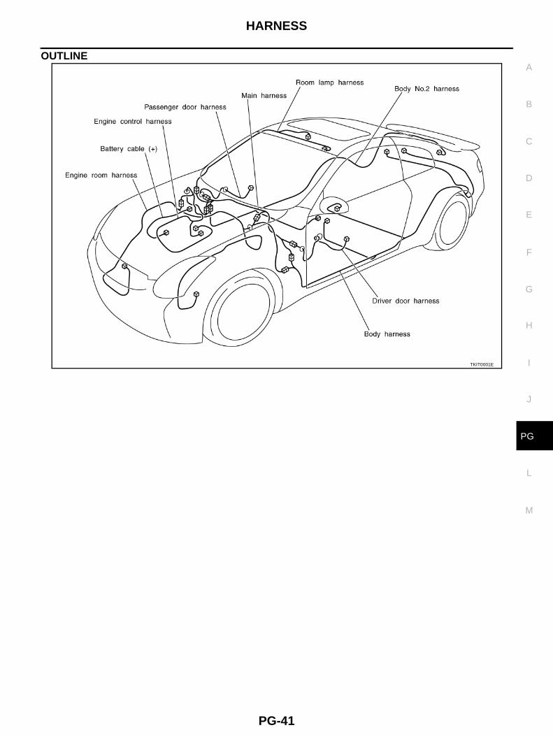
Harness Layout AKS003IB
HOW TO READ HARNESS LAYOUTThe following Harness Layouts use a map style grid to help locateconnectors on the drawings:● Main Harness● Engine Room Harness (Engine Compartment)● Engine Control Harness● Body Harness (Passenger Compartment)● Body No. 2 HarnessTo use the grid reference1. Find the desired connector number on the connector list.2. Find the grid reference.3. On the drawing, find the crossing of the grid reference letter column and number row.4. Find the connector number in the crossing zone.5. Follow the line (if used) to the connector.CONNECTOR SYMBOLMain symbols of connector (in Harness Layout) are indicated in the below.
SEL252V
CKIT0108E
HARNESS
PG-41
C
D
E
F
G
H
I
J
L
M
A
B
PG
OUTLINE
TKIT0001E
PG-42
HARNESS
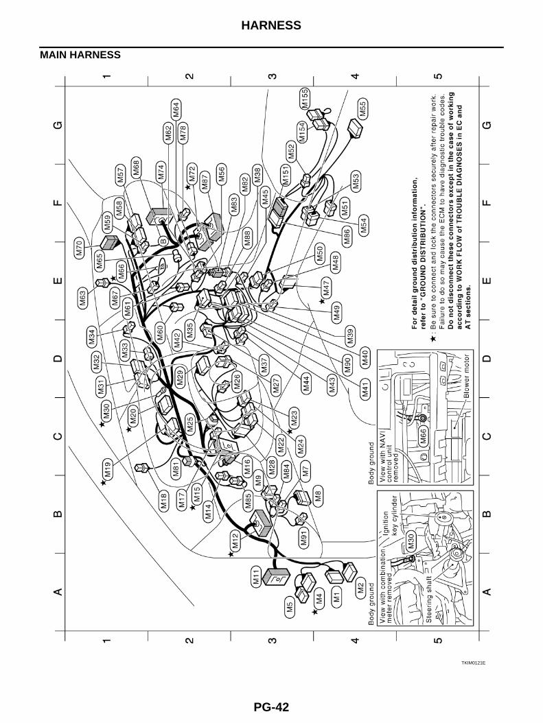
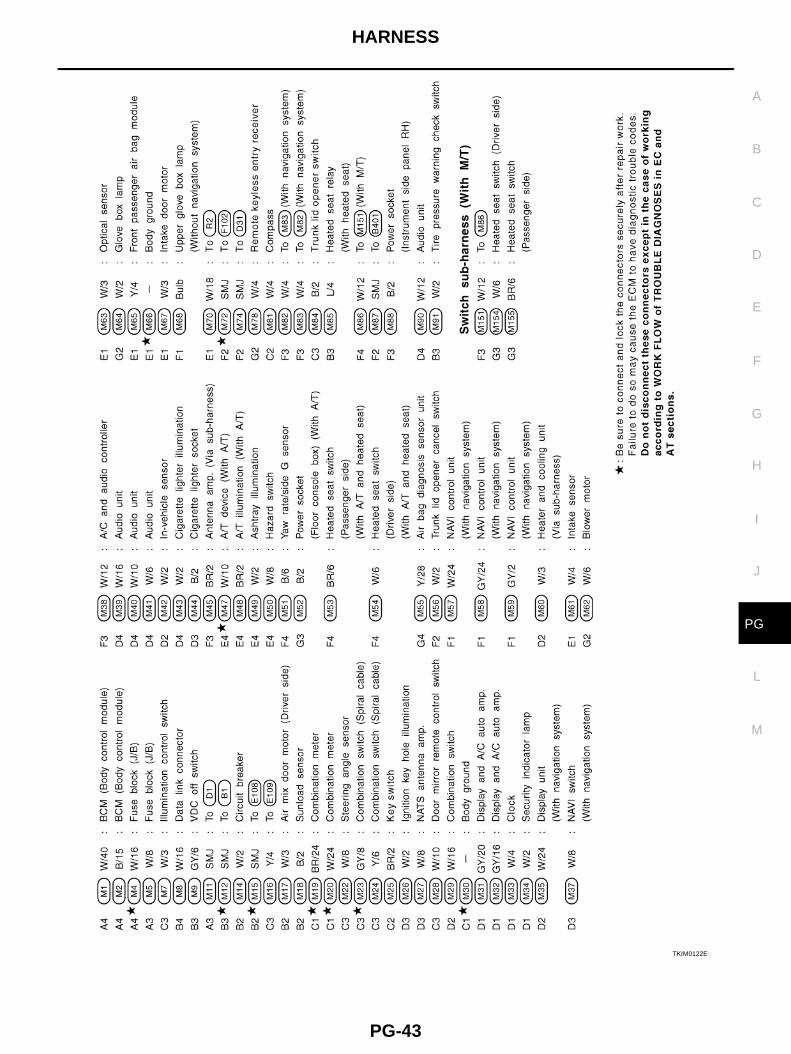
MAIN HARNESS
TKIM0121E
HARNESS
PG-43
C
D
E
F
G
H
I
J
L
M
A
B
PG
TKIM0122E
PG-44
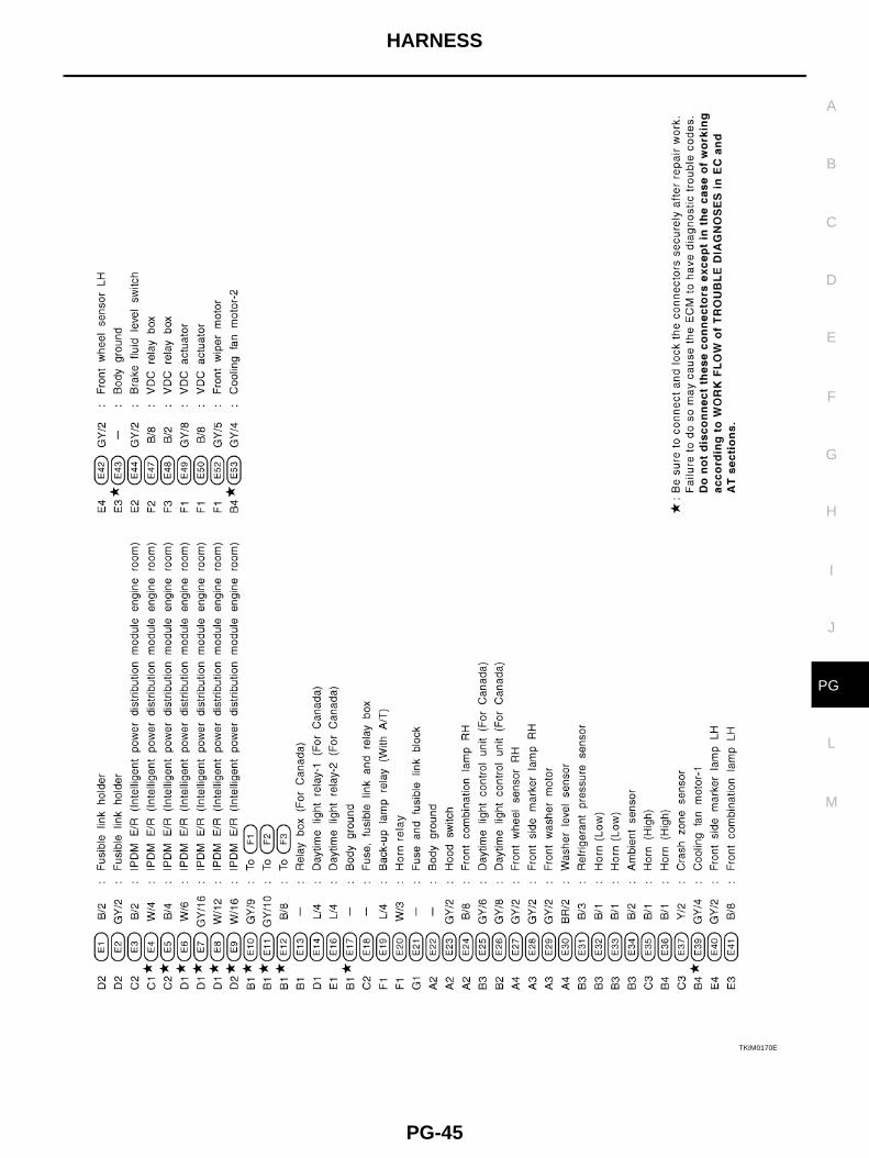
HARNESS
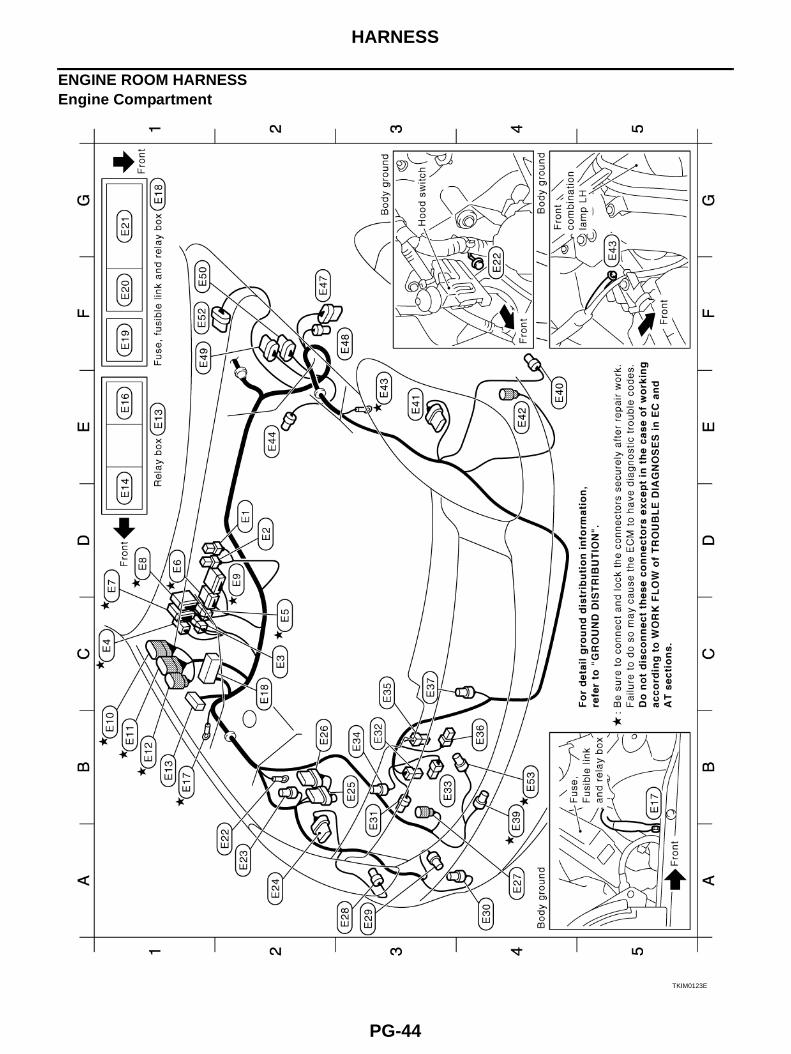
ENGINE ROOM HARNESSEngine Compartment
TKIM0123E
HARNESS
PG-45
C
D
E
F
G
H
I
J
L
M
A
B
PG
TKIM0170E
PG-46
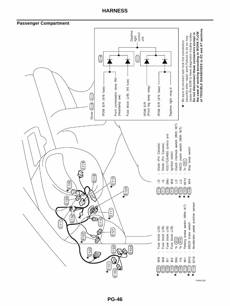
HARNESS
Passenger Compartment
TKIM0125E
HARNESS
PG-47
C
D
E
F
G
H
I
J
L
M
A
B
PG
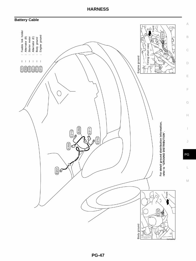
Battery Cable
TKIT0007E
PG-48
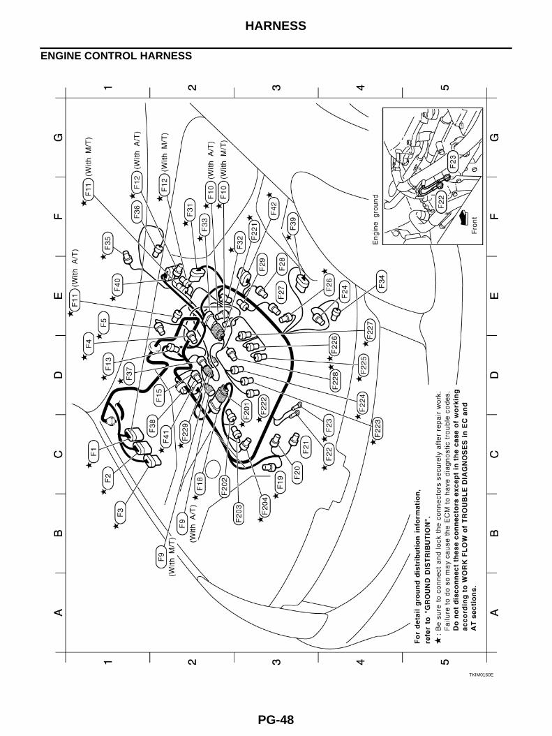
HARNESS
ENGINE CONTROL HARNESS
TKIM0160E
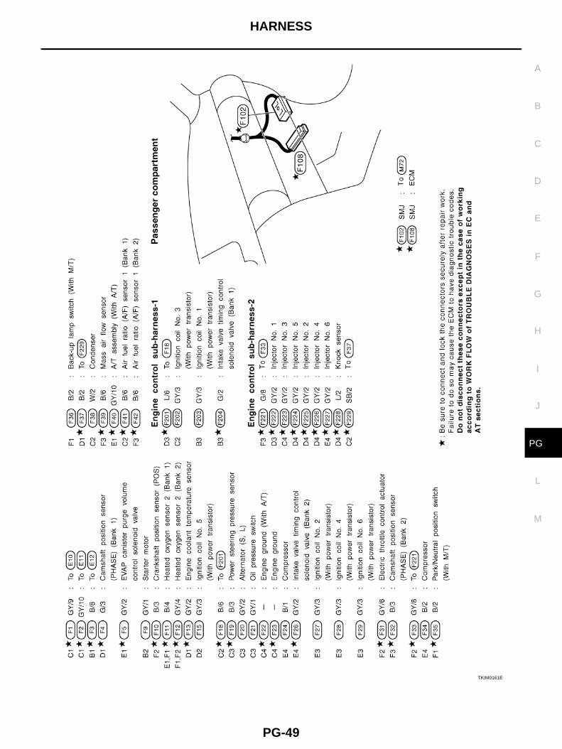
HARNESS
PG-49
C
D
E
F
G
H
I
J
L
M
A
B
PG
TKIM0161E
PG-50
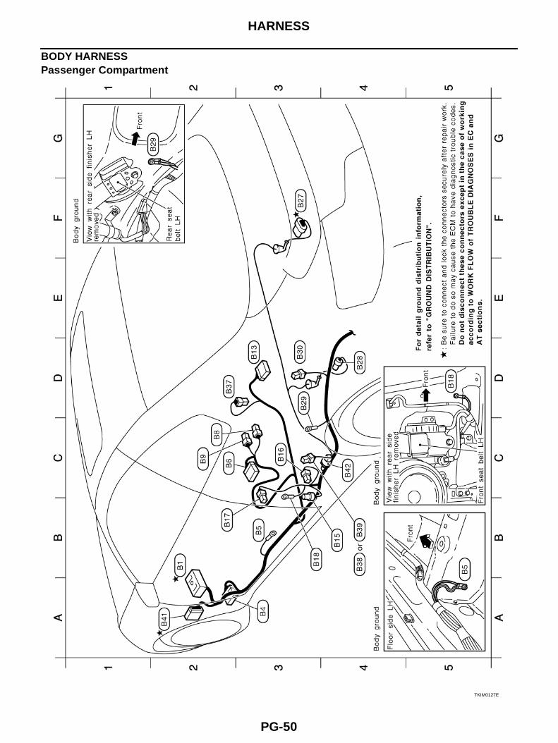
HARNESS
BODY HARNESSPassenger Compartment
TKIM0127E
HARNESS
PG-51
C
D
E
F
G
H
I
J
L
M
A
B
PG
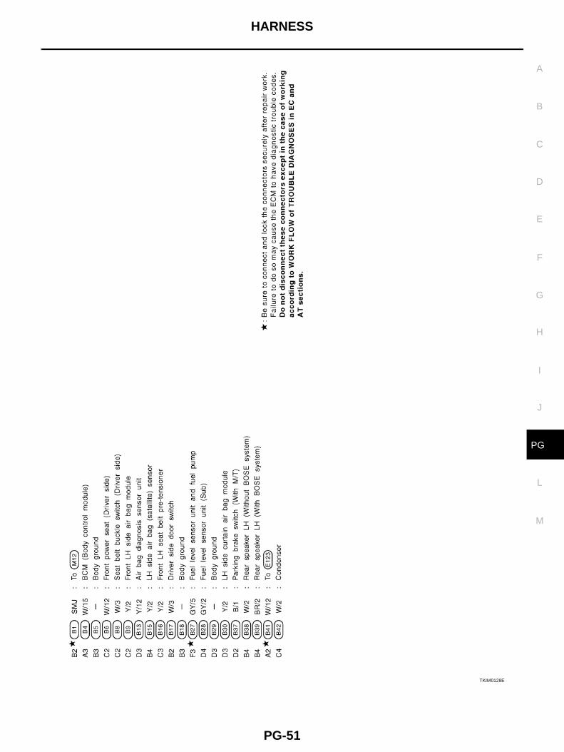
TKIM0128E
PG-52
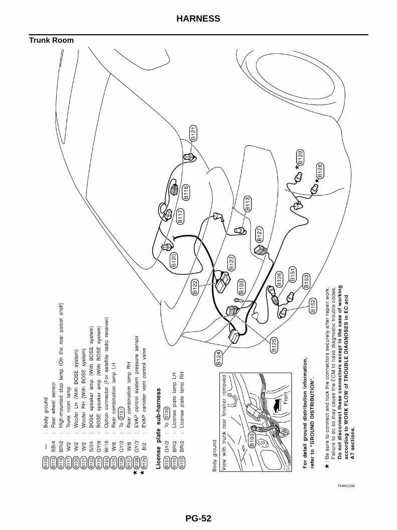
HARNESS
Trunk Room
TKIM0129E
HARNESS
PG-53
C
D
E
F
G
H
I
J
L
M
A
B
PG
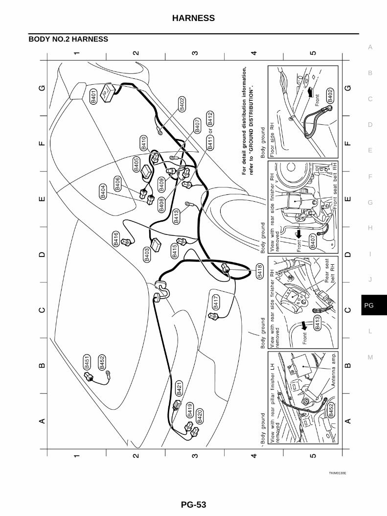
BODY NO.2 HARNESS
TKIM0130E
PG-54
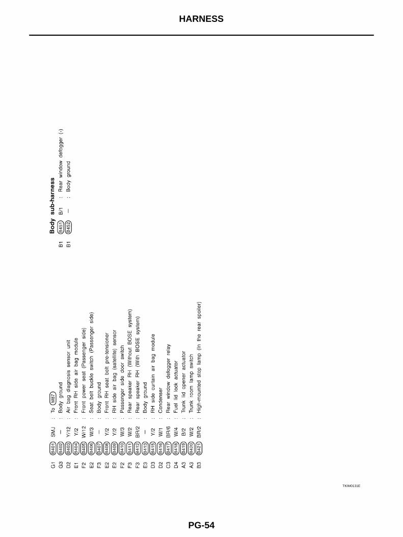
HARNESS
TKIM0131E
HARNESS
PG-55
C
D
E
F
G
H
I
J
L
M
A
B
PG
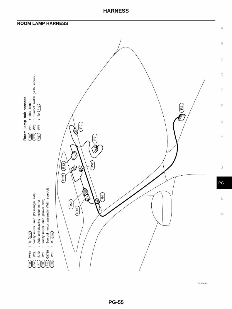
ROOM LAMP HARNESS
TKIT0015E
PG-56
HARNESS
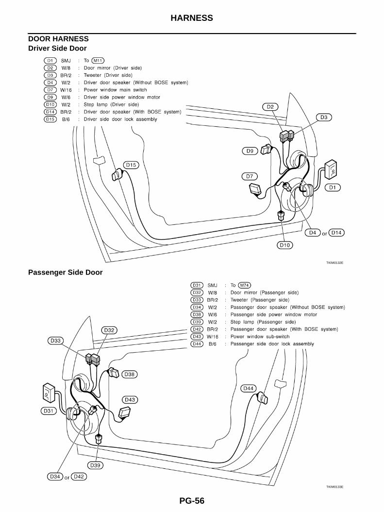
DOOR HARNESS Driver Side Door
Passenger Side DoorTKIM0132E
TKIM0133E
HARNESS
PG-57
C
D
E
F
G
H
I
J
L
M
A
B
PG
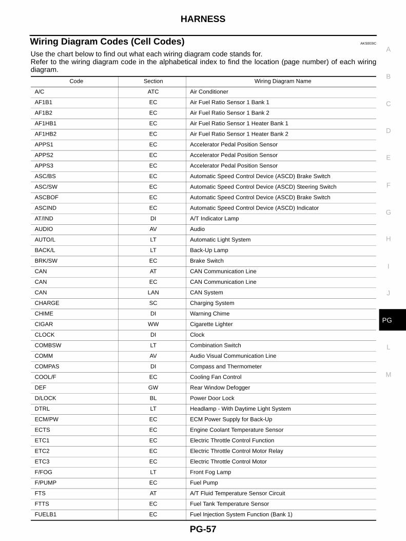
Wiring Diagram Codes (Cell Codes) AKS003IC
Use the chart below to find out what each wiring diagram code stands for.Refer to the wiring diagram code in the alphabetical index to find the location (page number) of each wiringdiagram.
Code Section Wiring Diagram Name
A/C ATC Air Conditioner
AF1B1 EC Air Fuel Ratio Sensor 1 Bank 1
AF1B2 EC Air Fuel Ratio Sensor 1 Bank 2
AF1HB1 EC Air Fuel Ratio Sensor 1 Heater Bank 1
AF1HB2 EC Air Fuel Ratio Sensor 1 Heater Bank 2
APPS1 EC Accelerator Pedal Position Sensor
APPS2 EC Accelerator Pedal Position Sensor
APPS3 EC Accelerator Pedal Position Sensor
ASC/BS EC Automatic Speed Control Device (ASCD) Brake Switch
ASC/SW EC Automatic Speed Control Device (ASCD) Steering Switch
ASCBOF EC Automatic Speed Control Device (ASCD) Brake Switch
ASCIND EC Automatic Speed Control Device (ASCD) Indicator
AT/IND DI A/T Indicator Lamp
AUDIO AV Audio
AUTO/L LT Automatic Light System
BACK/L LT Back-Up Lamp
BRK/SW EC Brake Switch
CAN AT CAN Communication Line
CAN EC CAN Communication Line
CAN LAN CAN System
CHARGE SC Charging System
CHIME DI Warning Chime
CIGAR WW Cigarette Lighter
CLOCK DI Clock
COMBSW LT Combination Switch
COMM AV Audio Visual Communication Line
COMPAS DI Compass and Thermometer
COOL/F EC Cooling Fan Control
DEF GW Rear Window Defogger
D/LOCK BL Power Door Lock
DTRL LT Headlamp - With Daytime Light System
ECM/PW EC ECM Power Supply for Back-Up
ECTS EC Engine Coolant Temperature Sensor
ETC1 EC Electric Throttle Control Function
ETC2 EC Electric Throttle Control Motor Relay
ETC3 EC Electric Throttle Control Motor
F/FOG LT Front Fog Lamp
F/PUMP EC Fuel Pump
FTS AT A/T Fluid Temperature Sensor Circuit
FTTS EC Fuel Tank Temperature Sensor
FUELB1 EC Fuel Injection System Function (Bank 1)
PG-58
HARNESS
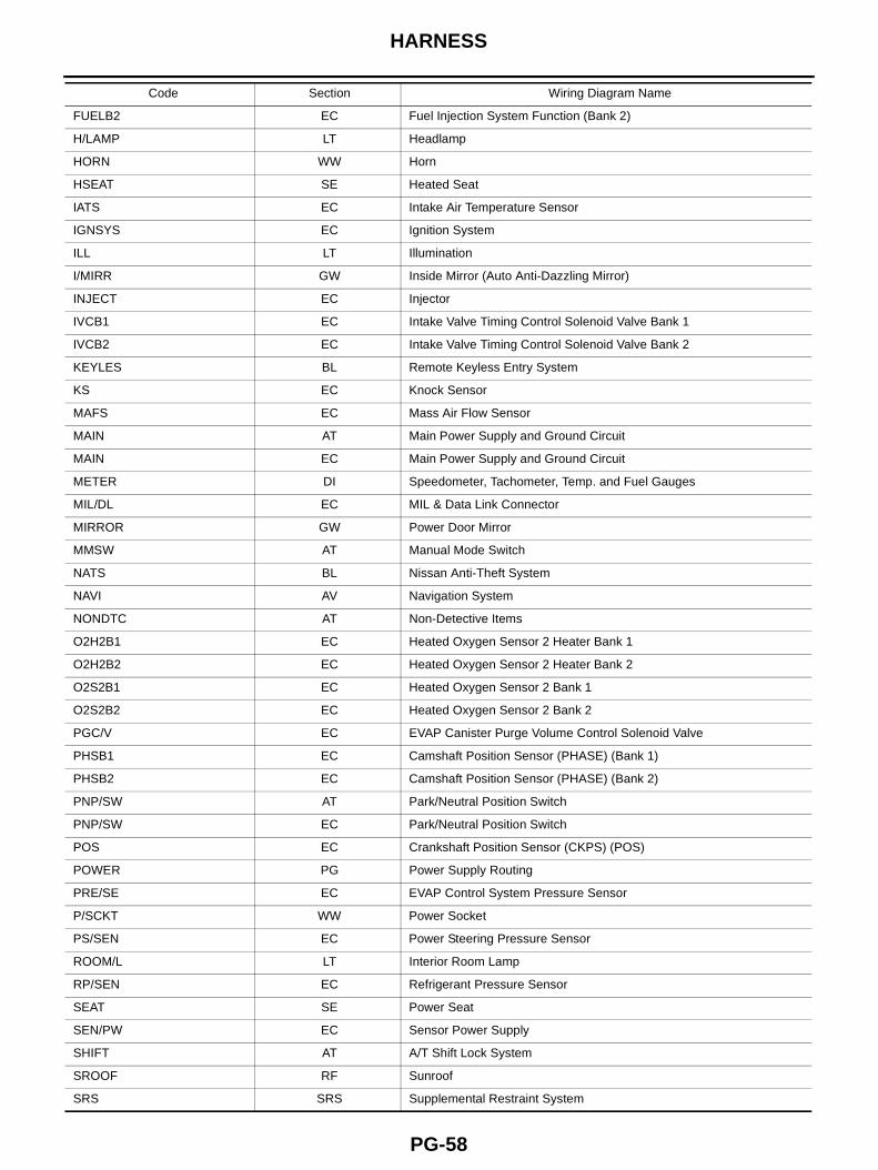
FUELB2 EC Fuel Injection System Function (Bank 2)
H/LAMP LT Headlamp
HORN WW Horn
HSEAT SE Heated Seat
IATS EC Intake Air Temperature Sensor
IGNSYS EC Ignition System
ILL LT Illumination
I/MIRR GW Inside Mirror (Auto Anti-Dazzling Mirror)
INJECT EC Injector
IVCB1 EC Intake Valve Timing Control Solenoid Valve Bank 1
IVCB2 EC Intake Valve Timing Control Solenoid Valve Bank 2
KEYLES BL Remote Keyless Entry System
KS EC Knock Sensor
MAFS EC Mass Air Flow Sensor
MAIN AT Main Power Supply and Ground Circuit
MAIN EC Main Power Supply and Ground Circuit
METER DI Speedometer, Tachometer, Temp. and Fuel Gauges
MIL/DL EC MIL & Data Link Connector
MIRROR GW Power Door Mirror
MMSW AT Manual Mode Switch
NATS BL Nissan Anti-Theft System
NAVI AV Navigation System
NONDTC AT Non-Detective Items
O2H2B1 EC Heated Oxygen Sensor 2 Heater Bank 1
O2H2B2 EC Heated Oxygen Sensor 2 Heater Bank 2
O2S2B1 EC Heated Oxygen Sensor 2 Bank 1
O2S2B2 EC Heated Oxygen Sensor 2 Bank 2
PGC/V EC EVAP Canister Purge Volume Control Solenoid Valve
PHSB1 EC Camshaft Position Sensor (PHASE) (Bank 1)
PHSB2 EC Camshaft Position Sensor (PHASE) (Bank 2)
PNP/SW AT Park/Neutral Position Switch
PNP/SW EC Park/Neutral Position Switch
POS EC Crankshaft Position Sensor (CKPS) (POS)
POWER PG Power Supply Routing
PRE/SE EC EVAP Control System Pressure Sensor
P/SCKT WW Power Socket
PS/SEN EC Power Steering Pressure Sensor
ROOM/L LT Interior Room Lamp
RP/SEN EC Refrigerant Pressure Sensor
SEAT SE Power Seat
SEN/PW EC Sensor Power Supply
SHIFT AT A/T Shift Lock System
SROOF RF Sunroof
SRS SRS Supplemental Restraint System
Code Section Wiring Diagram Name
HARNESS
PG-59
C
D
E
F
G
H
I
J
L
M
A
B
PG
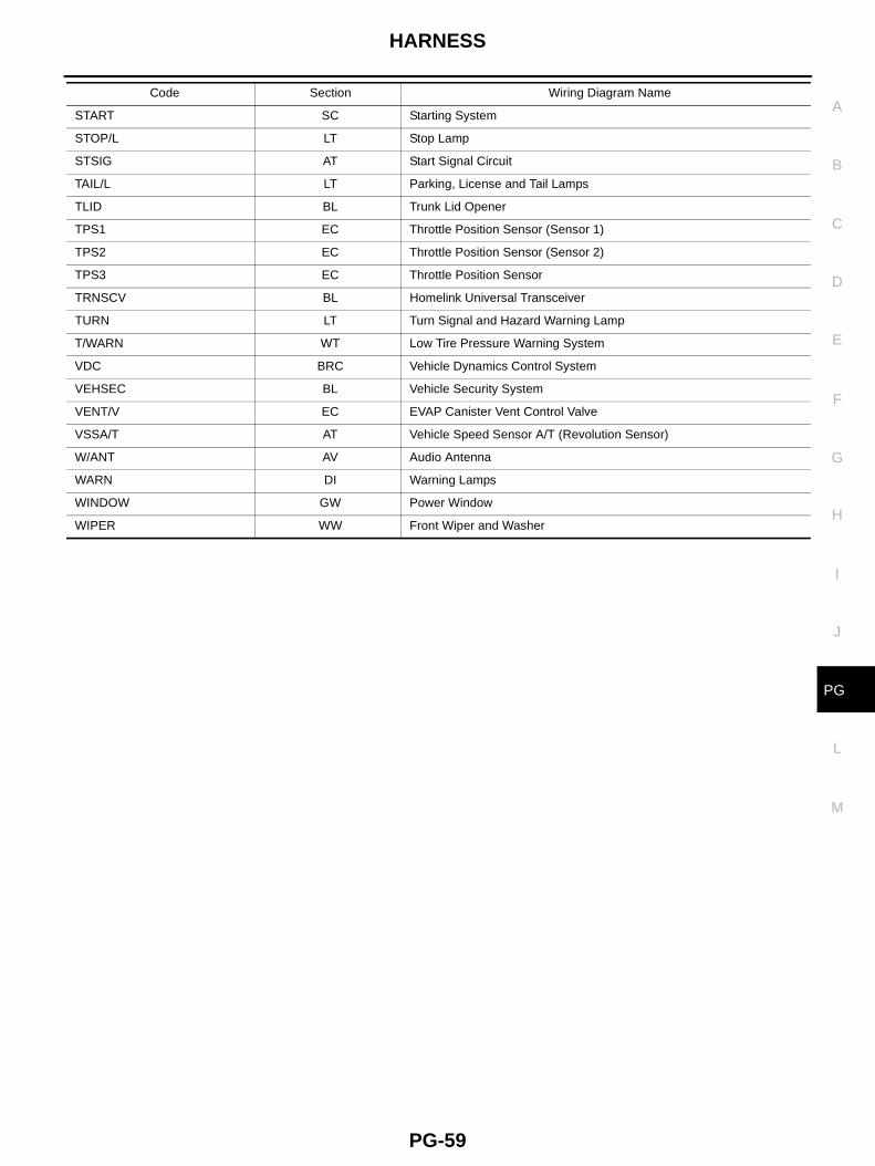
START SC Starting System
STOP/L LT Stop Lamp
STSIG AT Start Signal Circuit
TAIL/L LT Parking, License and Tail Lamps
TLID BL Trunk Lid Opener
TPS1 EC Throttle Position Sensor (Sensor 1)
TPS2 EC Throttle Position Sensor (Sensor 2)
TPS3 EC Throttle Position Sensor
TRNSCV BL Homelink Universal Transceiver
TURN LT Turn Signal and Hazard Warning Lamp
T/WARN WT Low Tire Pressure Warning System
VDC BRC Vehicle Dynamics Control System
VEHSEC BL Vehicle Security System
VENT/V EC EVAP Canister Vent Control Valve
VSSA/T AT Vehicle Speed Sensor A/T (Revolution Sensor)
W/ANT AV Audio Antenna
WARN DI Warning Lamps
WINDOW GW Power Window
WIPER WW Front Wiper and Washer
Code Section Wiring Diagram Name
PG-60
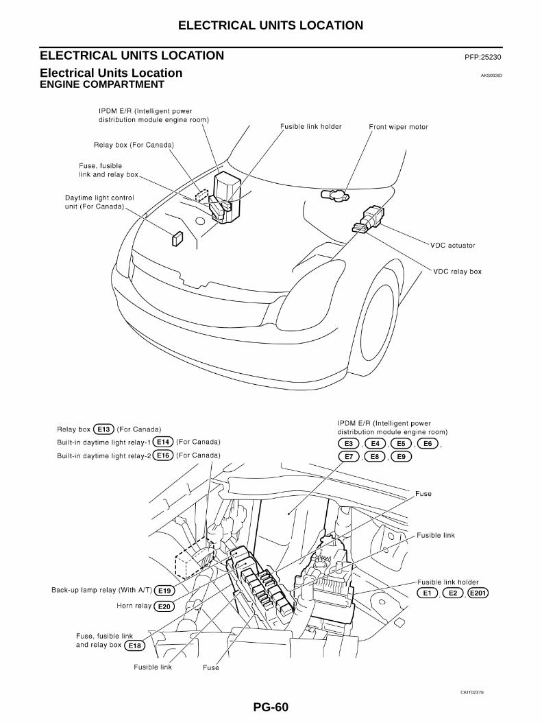
ELECTRICAL UNITS LOCATION
ELECTRICAL UNITS LOCATION PFP:25230
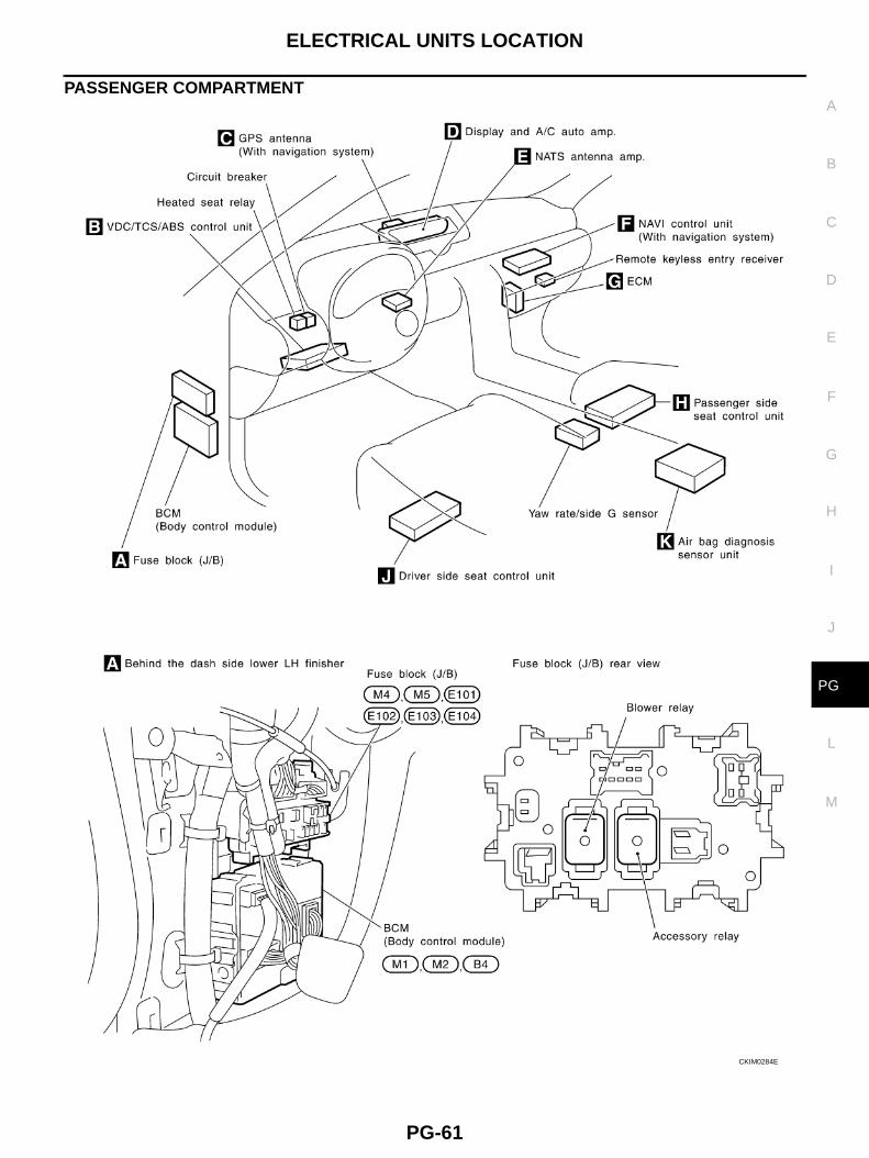
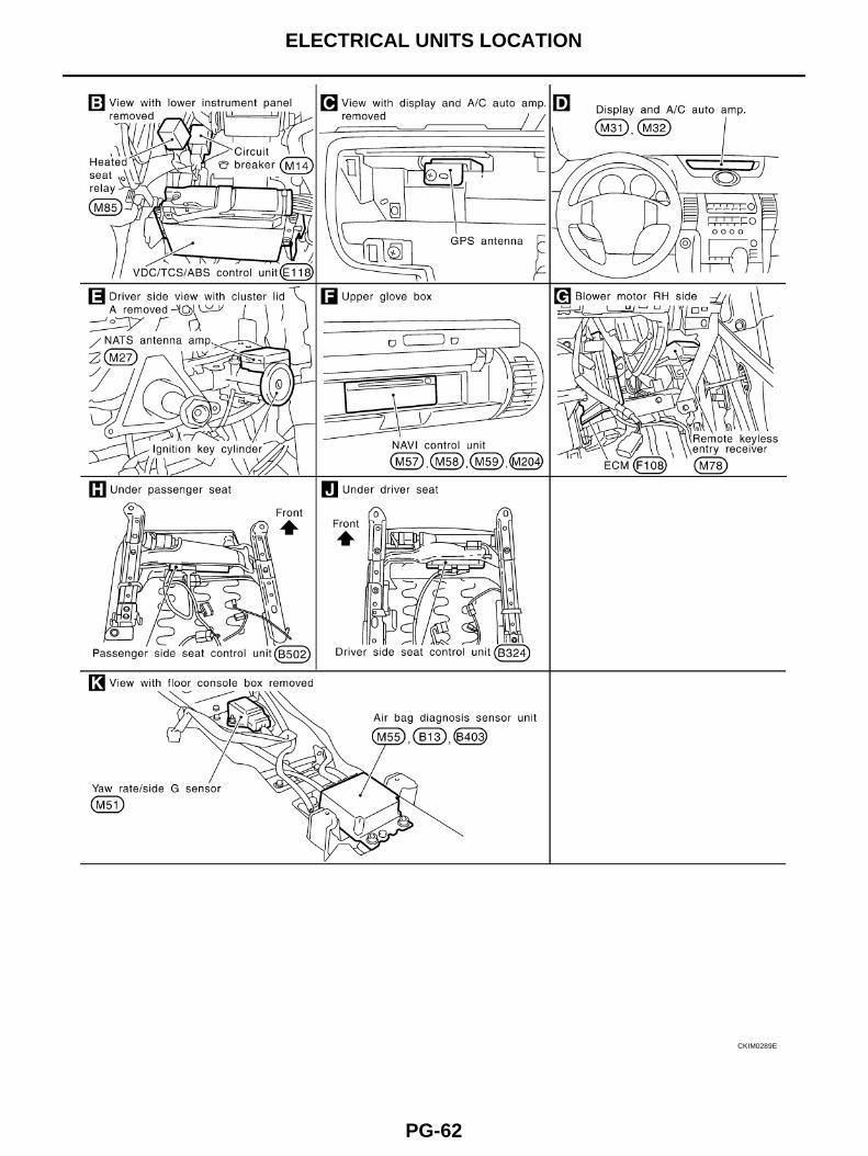
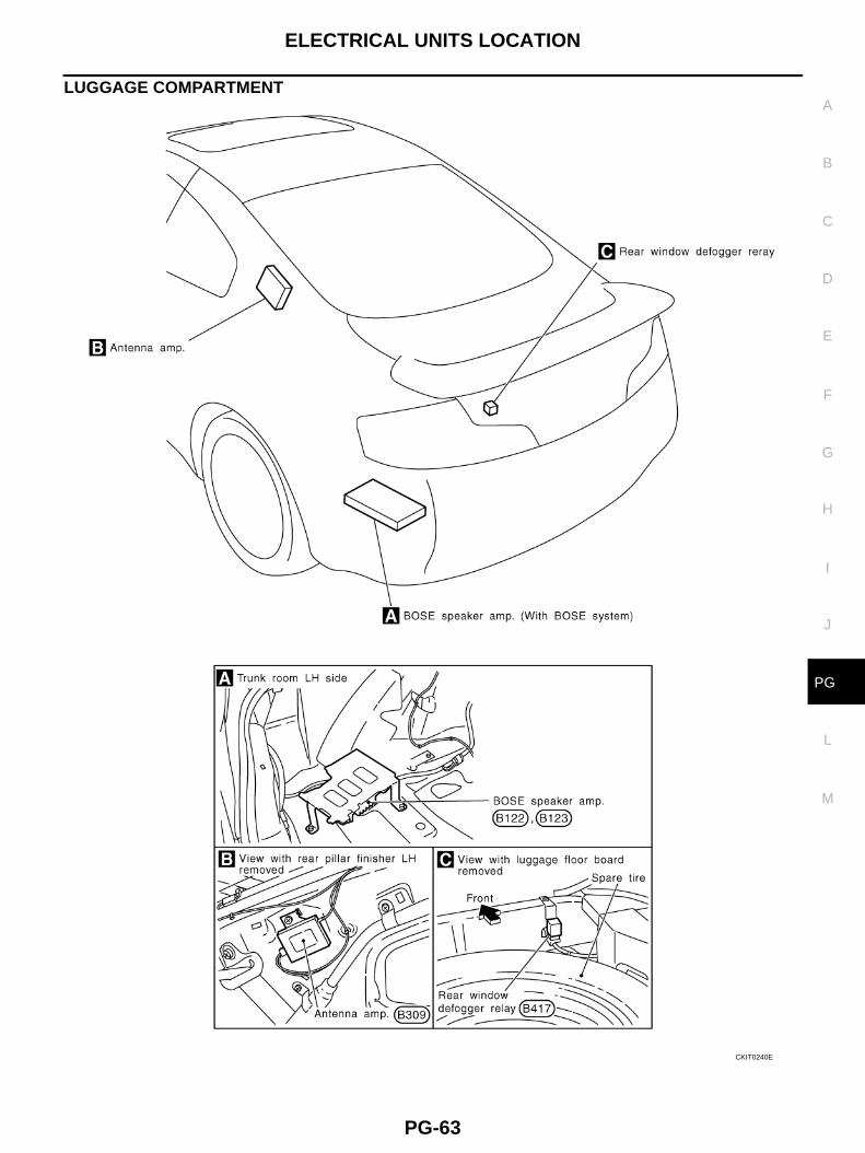
Electrical Units Location AKS003ID
ENGINE COMPARTMENT
CKIT0237E
ELECTRICAL UNITS LOCATION
PG-61
C
D
E
F
G
H
I
J
L
M
A
B
PG
PASSENGER COMPARTMENT
CKIM0284E
PG-62
ELECTRICAL UNITS LOCATION
CKIM0289E
ELECTRICAL UNITS LOCATION
PG-63
C
D
E
F
G
H
I
J
L
M
A
B
PG
LUGGAGE COMPARTMENT
CKIT0240E
PG-64
HARNESS CONNECTOR
HARNESS CONNECTOR PFP:00011
Description AKS003IE
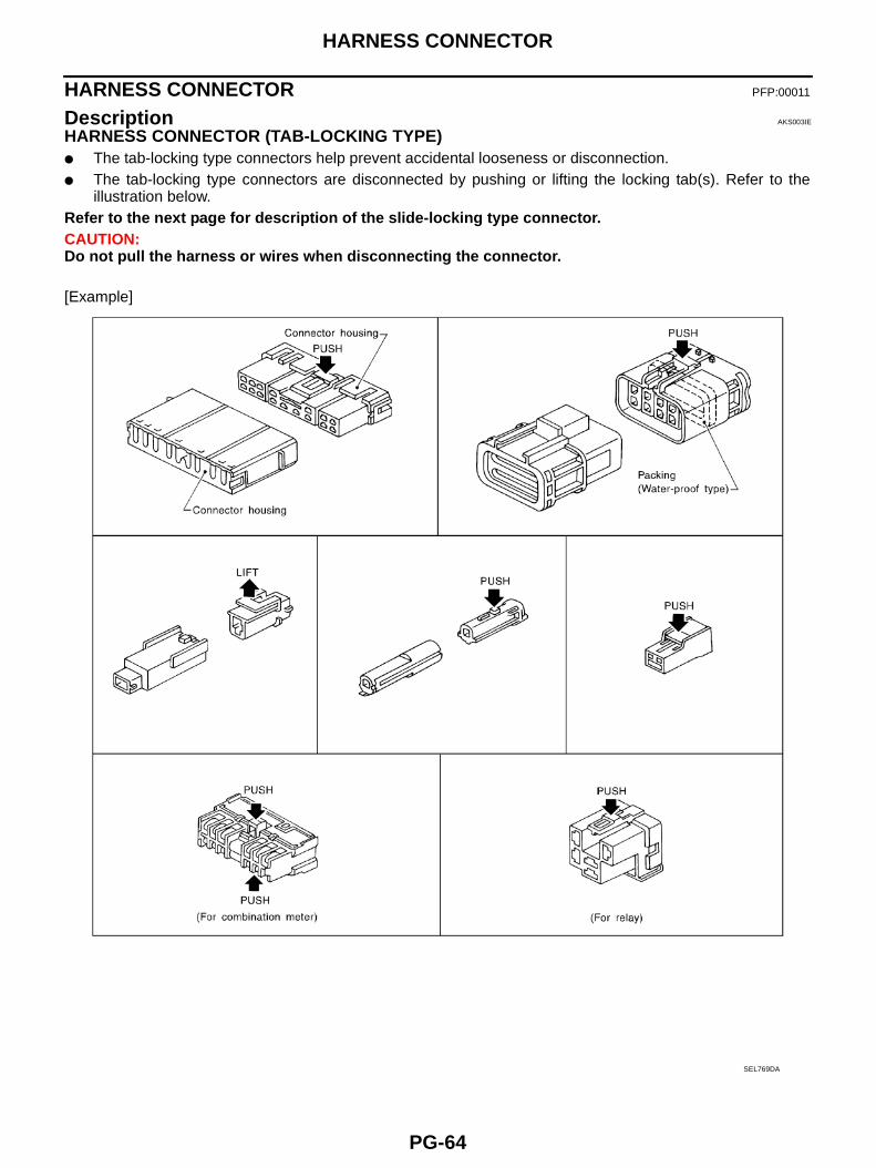
HARNESS CONNECTOR (TAB-LOCKING TYPE)● The tab-locking type connectors help prevent accidental looseness or disconnection.● The tab-locking type connectors are disconnected by pushing or lifting the locking tab(s). Refer to the
illustration below.Refer to the next page for description of the slide-locking type connector.CAUTION:Do not pull the harness or wires when disconnecting the connector.
[Example]
SEL769DA
HARNESS CONNECTOR
PG-65
C
D
E
F
G
H
I
J
L
M
A
B
PG
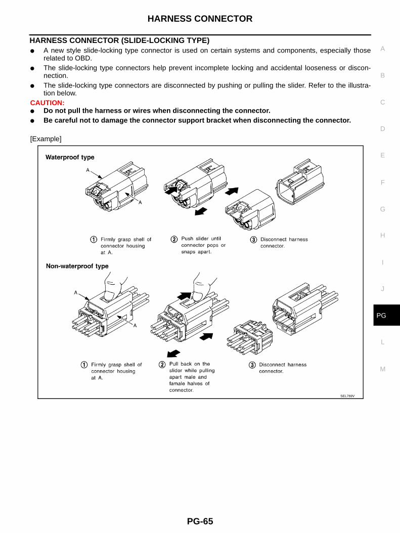
HARNESS CONNECTOR (SLIDE-LOCKING TYPE)● A new style slide-locking type connector is used on certain systems and components, especially those
related to OBD.● The slide-locking type connectors help prevent incomplete locking and accidental looseness or discon-
nection.● The slide-locking type connectors are disconnected by pushing or pulling the slider. Refer to the illustra-
tion below.CAUTION:● Do not pull the harness or wires when disconnecting the connector.● Be careful not to damage the connector support bracket when disconnecting the connector.
[Example]
SEL769V
PG-66
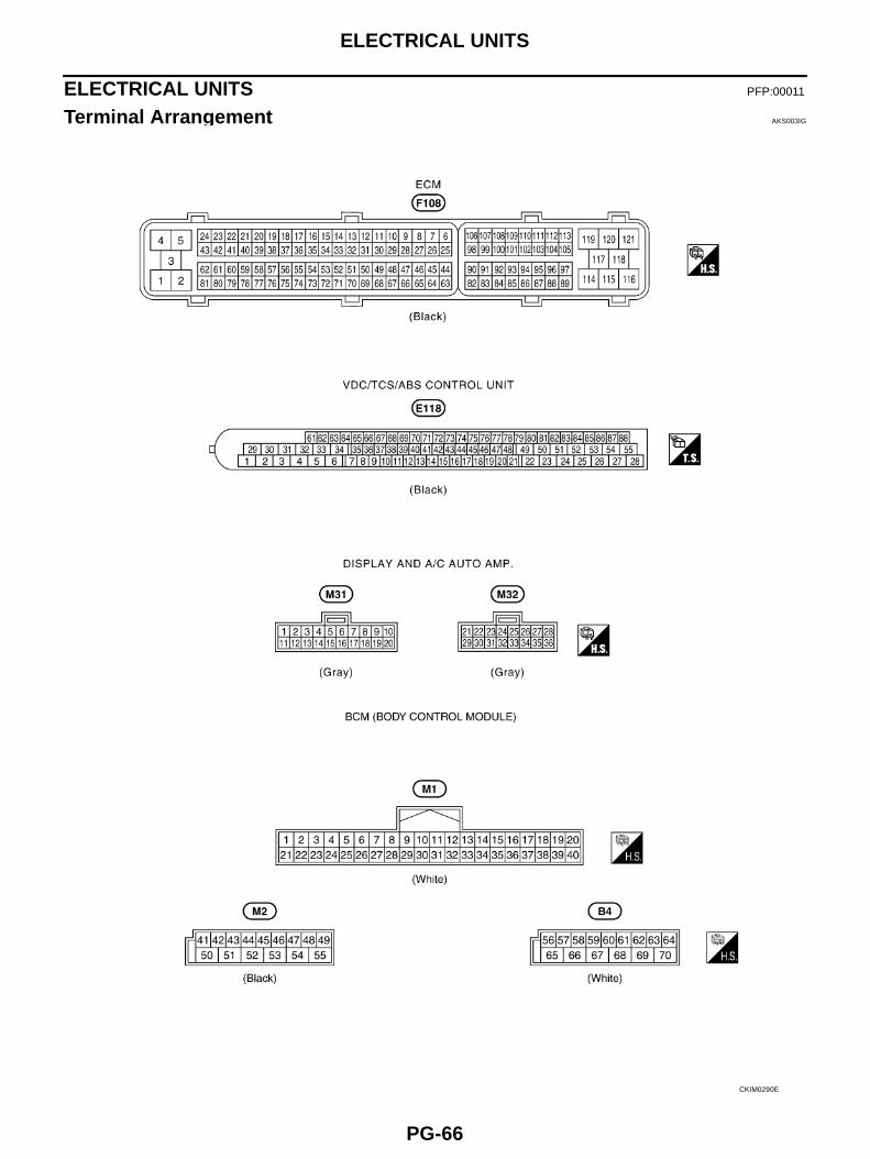
ELECTRICAL UNITS
ELECTRICAL UNITS PFP:00011
Terminal Arrangement AKS003IG
CKIM0290E
SMJ (SUPER MULTIPLE JUNCTION)
PG-67
C
D
E
F
G
H
I
J
L
M
A
B
PG
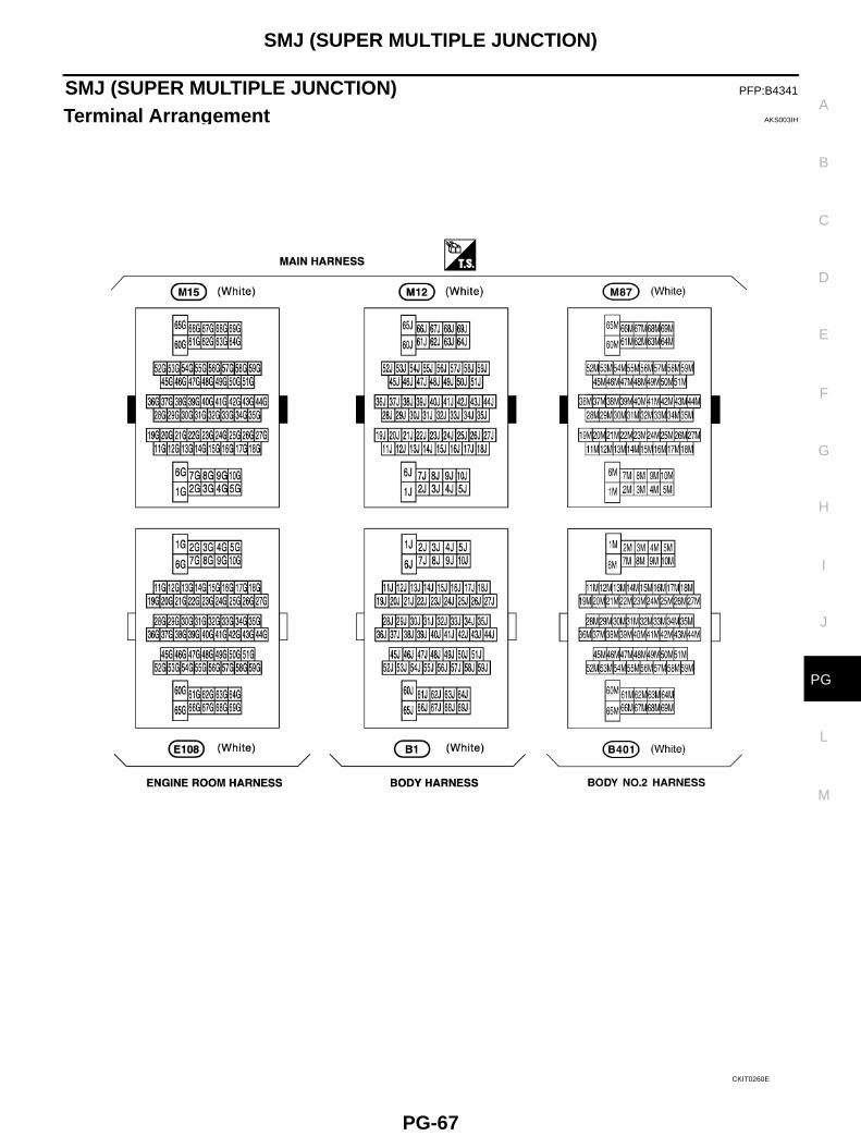
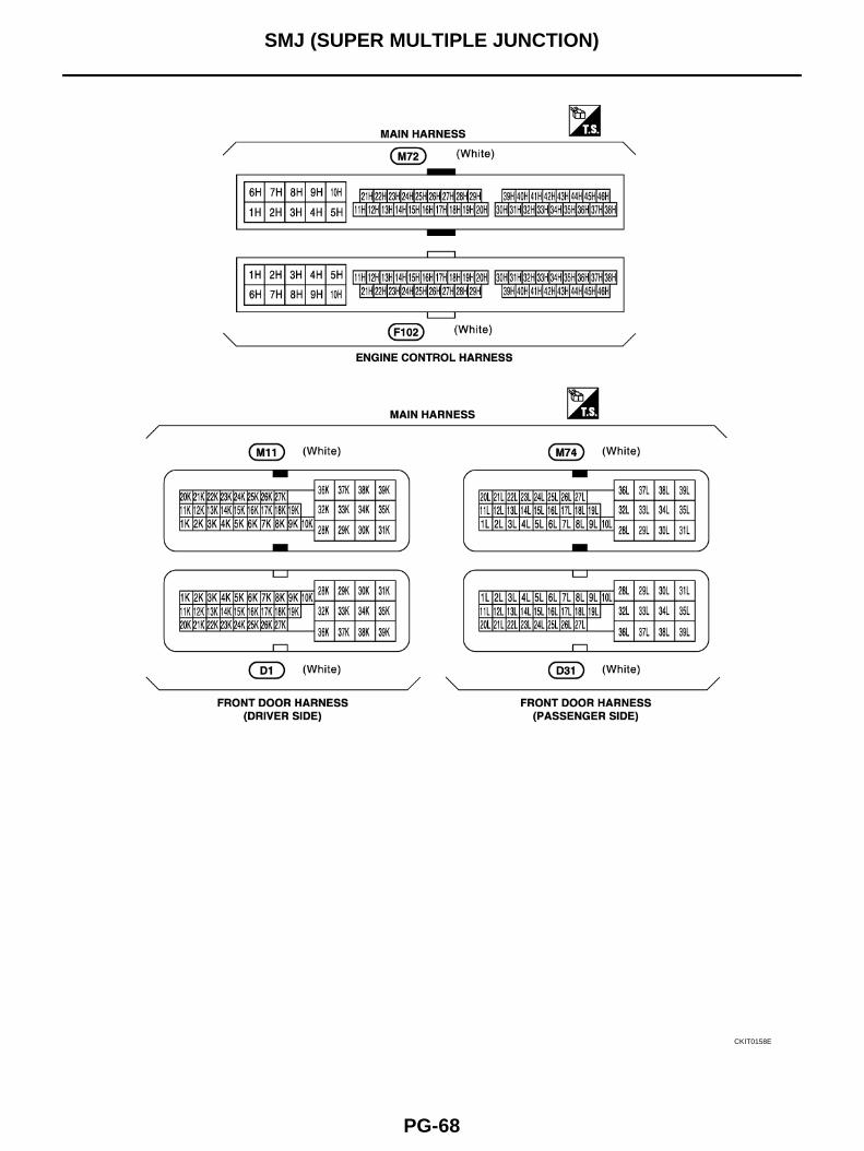
SMJ (SUPER MULTIPLE JUNCTION) PFP:B4341
Terminal Arrangement AKS003IH
CKIT0260E
PG-68
SMJ (SUPER MULTIPLE JUNCTION)
CKIT0158E
STANDARDIZED RELAY
PG-69
C
D
E
F
G
H
I
J
L
M
A
B
PG
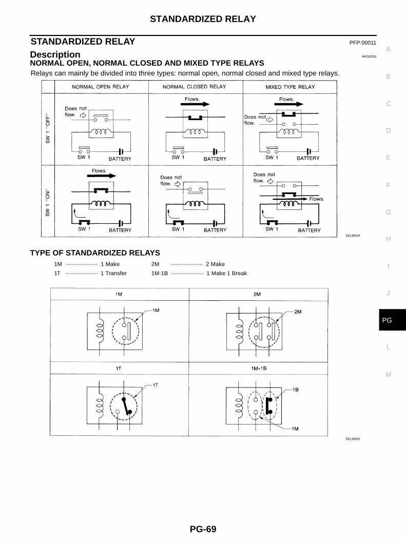
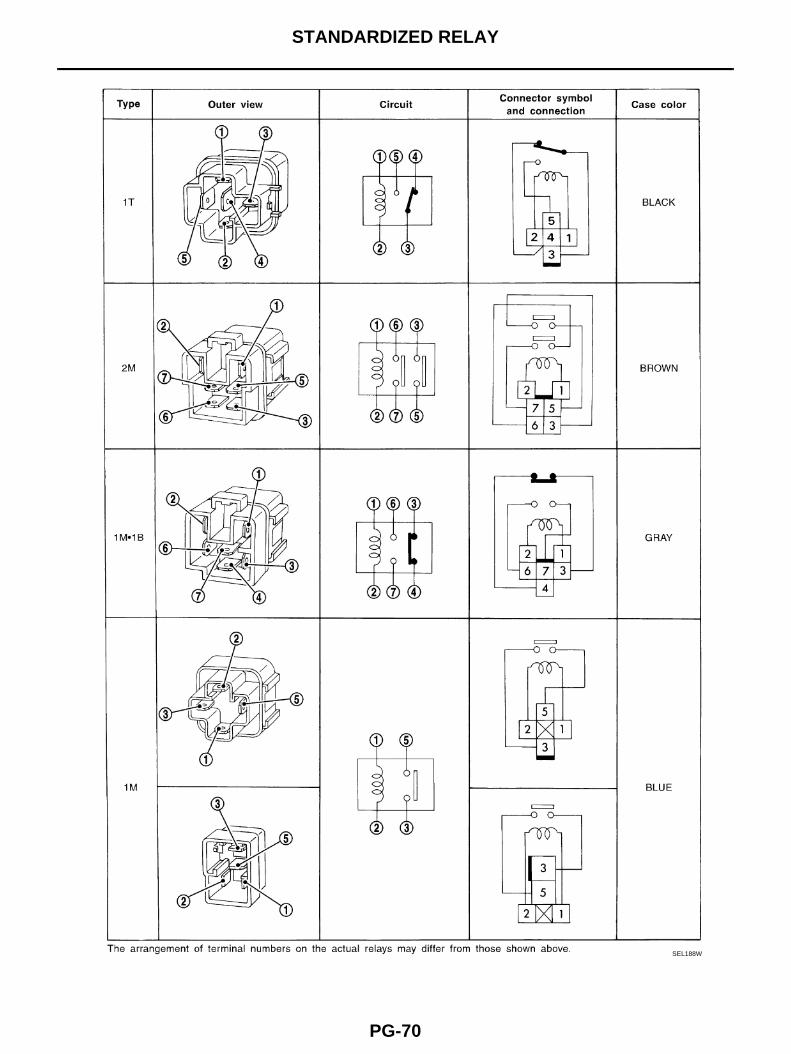
STANDARDIZED RELAY PFP:00011
Description AKS003II
NORMAL OPEN, NORMAL CLOSED AND MIXED TYPE RELAYSRelays can mainly be divided into three types: normal open, normal closed and mixed type relays.
TYPE OF STANDARDIZED RELAYS
SEL881H
1M ···················· 1 Make 2M ···················· 2 Make
1T ···················· 1 Transfer 1M·1B ···················· 1 Make 1 Break
SEL882H
PG-70
STANDARDIZED RELAY
SEL188W
FUSE BLOCK - JUNCTION BOX (J/B)
PG-71
C
D
E
F
G
H
I
J
L
M
A
B
PG
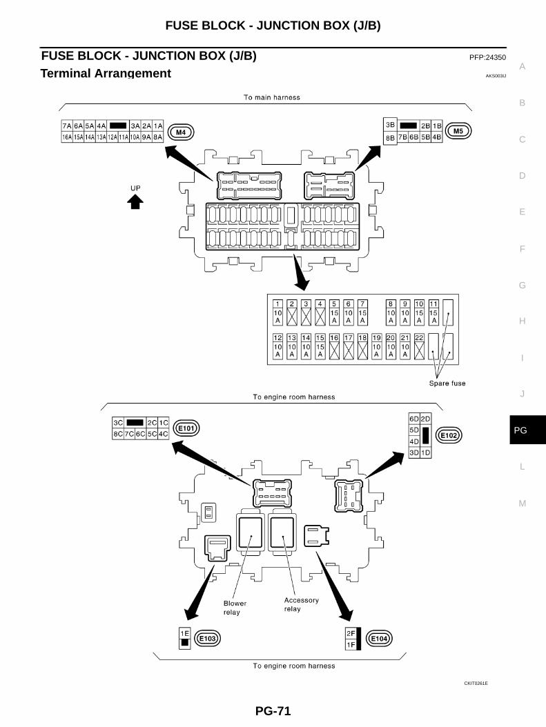
FUSE BLOCK - JUNCTION BOX (J/B) PFP:24350
Terminal Arrangement AKS003IJ
CKIT0261E
PG-72
FUSE, FUSIBLE LINK AND RELAY BOX
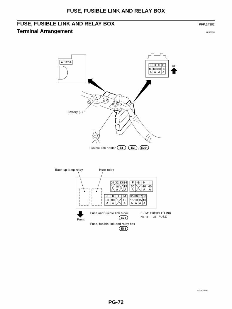
FUSE, FUSIBLE LINK AND RELAY BOX PFP:24382
Terminal Arrangement AKS003IK
CKIM0285E