Embed Size (px)
Citation preview
1
2
3
4
5
6
7
8
Document Number: DSP1015
Date: 2009-08-14
Version: 1.1.0
Power Supply Profile
Document Type: Specification
Document Status: DMTF Standard
Document Language: E
9
Power Supply Profile DSP1015
2 DMTF Standard Version 1.1.0
Copyright Notice 10
Copyright © 2007-2009 Distributed Management Task Force, Inc. (DMTF). All rights reserved. 11
12 13 14 15
16 17 18 19 20 21 22 23 24 25 26 27 28
29 30
DMTF is a not-for-profit association of industry members dedicated to promoting enterprise and systems management and interoperability. Members and non-members may reproduce DMTF specifications and documents, provided that correct attribution is given. As DMTF specifications may be revised from time to time, the particular version and release date should always be noted.
Implementation of certain elements of this standard or proposed standard may be subject to third party patent rights, including provisional patent rights (herein "patent rights"). DMTF makes no representations to users of the standard as to the existence of such rights, and is not responsible to recognize, disclose, or identify any or all such third party patent right, owners or claimants, nor for any incomplete or inaccurate identification or disclosure of such rights, owners or claimants. DMTF shall have no liability to any party, in any manner or circumstance, under any legal theory whatsoever, for failure to recognize, disclose, or identify any such third party patent rights, or for such party’s reliance on the standard or incorporation thereof in its product, protocols or testing procedures. DMTF shall have no liability to any party implementing such standard, whether such implementation is foreseeable or not, nor to any patent owner or claimant, and shall have no liability or responsibility for costs or losses incurred if a standard is withdrawn or modified after publication, and shall be indemnified and held harmless by any party implementing the standard from any and all claims of infringement by a patent owner for such implementations.
For information about patents held by third-parties which have notified the DMTF that, in their opinion, such patent may relate to or impact implementations of DMTF standards, visit http://www.dmtf.org/about/policies/disclosures.php. 31
DSP1015 Power Supply Profile
Version 1.1.0 DMTF Standard 3
CONTENTS 32
33 34 35 36 37 38 39 40 41 42 43 44 45 46 47 48 49 50 51 52 53 54 55 56 57 58 59 60 61 62 63 64 65 66 67 68 69 70 71 72 73 74 75 76 77 78 79 80 81 82 83 84
Foreword ....................................................................................................................................................... 6 Introduction ................................................................................................................................................... 7 1 Scope .................................................................................................................................................... 8 2 Normative References........................................................................................................................... 8
2.1 Approved References ................................................................................................................. 8 2.2 Other References........................................................................................................................ 8
3 Terms and Definitions ........................................................................................................................... 8 4 Symbols and Abbreviated Terms ........................................................................................................ 10 5 Synopsis.............................................................................................................................................. 10 6 Description .......................................................................................................................................... 10
6.1 General Modeling...................................................................................................................... 10 6.2 Power Supply Redundancy Modeling....................................................................................... 11 6.3 Power Measurements Modeling ............................................................................................... 11
7 Implementation Requirements ............................................................................................................ 12 7.1 CIM_PowerSupply .................................................................................................................... 12 7.2 CIM_EnabledLogicalElementCapabilities................................................................................. 12 7.3 Power Supply State Management ............................................................................................ 12 7.4 CIM_PowerSupply.RequestedState ......................................................................................... 13 7.5 CIM_PowerSupply.EnabledState ............................................................................................. 13 7.6 CIM_SystemDevice and CIM_SuppliesPower ......................................................................... 14 7.7 Modeling Power Supply Redundancy....................................................................................... 14 7.8 CIM_PowerSupply.ElementName ............................................................................................ 15 7.9 Modeling Power Measurement Sensor..................................................................................... 15 7.10 Power Metrics ........................................................................................................................... 16
8 Methods............................................................................................................................................... 20 8.1 Method: CIM_PowerSupply.RequestStateChange( ) ............................................................... 20 8.2 Method: CIM_RedundancySet.Failover( ) ................................................................................ 21 8.3 Profile Conventions for Operations........................................................................................... 22 8.4 CIM_ElementCapabilities Operations....................................................................................... 22 8.5 CIM_EnabledLogicalElementCapabilities Operations .............................................................. 22 8.6 CIM_HostedCollection Operations ........................................................................................... 22 8.7 CIM_IsSpare Operations .......................................................................................................... 23 8.8 CIM_MemberOfCollection Operations...................................................................................... 23 8.9 CIM_OwningCollectionElement Operations ............................................................................. 23 8.10 CIM_PowerSupply Operations ................................................................................................. 24 8.11 CIM_RedundancySet Operations ............................................................................................. 24 8.12 CIM_SuppliesPower Operations............................................................................................... 24 8.13 CIM_SystemDevice Operations................................................................................................ 25
9 Use Cases........................................................................................................................................... 25 9.1 Object Diagrams ....................................................................................................................... 25 9.2 Power Sensor Information ........................................................................................................ 28 9.3 Power Metrics ........................................................................................................................... 28 9.4 Retrieve the Power Supply’s Power Output Information .......................................................... 30 9.5 Reset the Power Supply ........................................................................................................... 31 9.6 Retrieve the Power Supply Redundancy Status....................................................................... 31 9.7 Find the Elements to Which the Power Supply Supplies Power .............................................. 31 9.8 Determine Whether the CIM_PowerSupply.ElementName Is Modifiable ................................ 31
10 CIM Elements...................................................................................................................................... 31 10.1 CIM_BaseMetricDefinition ........................................................................................................ 32 10.2 CIM_BaseMetricValue .............................................................................................................. 33 10.3 CIM_ElementCapabilities ......................................................................................................... 33 10.4 CIM_EnabledLogicalElementCapabilities................................................................................. 33
Power Supply Profile DSP1015
4 DMTF Standard Version 1.1.0
10.5 CIM_HostedCollection .............................................................................................................. 34 85 86 87 88 89 90 91 92 93 94 95 96 97 98 99
10.6 CIM_IsSpare ............................................................................................................................. 34 10.7 CIM_MemberOfCollection ........................................................................................................ 34 10.8 CIM_NumericSensor — Input Power Measurement Sensor.................................................... 35 10.9 CIM_NumericSensor — Output Power Measurement Sensor ................................................. 35 10.10 CIM_PowerSupply .................................................................................................................... 35 10.11 CIM_RedundancySet................................................................................................................ 36 10.12 CIM_RegisteredProfile.............................................................................................................. 36 10.13 CIM_Sensor — Input Power Measurement Sensor ................................................................. 36 10.14 CIM_Sensor — Output Power Measurement Sensor............................................................... 36 10.15 CIM_SystemDevice .................................................................................................................. 37 10.16 CIM_OwningCollectionElement ................................................................................................ 37 10.17 CIM_SuppliesPower ................................................................................................................. 37
ANNEX A (informative) Change Log.......................................................................................................... 38
Figures 100
101 102 103 104 105 106 107 108
Figure 1 – Power Supply Profile: Class Diagram........................................................................................ 11 Figure 2 – Power Supply Profile: Object Diagram ...................................................................................... 26 Figure 3 – Power Supply Profile: Redundancy Object Diagram................................................................. 27 Figure 4 – Power Supply Profile: Dedicated Power Supply........................................................................ 27 Figure 5 – Power Supply Profile: Power Sensors....................................................................................... 28 Figure 6 – Power Supply Profile: Power Metrics ........................................................................................ 29 Figure 7 – Power Supply Profile: Power Metrics with Breakdown Dimensions .......................................... 30
Tables 109
110 111 112 113 114 115 116 117 118 119 120 121 122 123 124 125 126 127 128 129 130 131
Table 1 – Related Profiles........................................................................................................................... 10 Table 2 – EnabledState Value Description ................................................................................................. 13 Table 3 – System Power Metrics ................................................................................................................ 17 Table 4 – Power Supply Metrics ................................................................................................................. 18 Table 5 – Power Supply Metric Breakdown Dimensions ............................................................................ 18 Table 6 – Examples of Values for the CIM_BaseMetricValue.BreakdownDimension and
CIM_BaseMetricValue.BreakdownValue Properties ........................................................ 19 Table 7 – Power Supply Profile Metrics ...................................................................................................... 19 Table 8 – CIM_PowerSupply.RequestStateChange( ) Method: Return Code Values................................ 20 Table 9 – CIM_PowerSupply.RequestStateChange( ) Method: Parameters ............................................. 20 Table 10 – CIM_RedundancySet.Failover( ) Method: Return Code Values............................................... 21 Table 11 – CIM_RedundancySet.Failover( ) Method: Parameters............................................................. 22 Table 12 – CIM_ElementCapabilities Operations....................................................................................... 22 Table 13 – CIM_HostedCollection Operations............................................................................................ 23 Table 14 – CIM_IsSpare Operations .......................................................................................................... 23 Table 15 – CIM_MemberOfCollection Operations...................................................................................... 23 Table 16 – CIM_OwningCollectionElement Operations ............................................................................. 24 Table 17 – CIM_PowerSupply Operations.................................................................................................. 24 Table 18 – CIM_SuppliesPower Operations............................................................................................... 25 Table 19 – CIM_SystemDevice Operations................................................................................................ 25 Table 20 – CIM Elements: Power Supply Profile ........................................................................................ 32 Table 21 – Class: CIM_BaseMetricDefinition ............................................................................................. 32
DSP1015 Power Supply Profile
Version 1.1.0 DMTF Standard 5
Table 22 – Class: CIM_BaseMetricDefinition – Histogram......................................................................... 32 132 133 134 135 136 137 138 139 140 141 142 143 144 145 146 147 148
149
Table 23 – Class: CIM_BaseMetricValue ................................................................................................... 33 Table 24 – CIM_ElementCapabilities.......................................................................................................... 33 Table 25 – CIM_EnabledLogicalElementCapabilities................................................................................. 33 Table 26 – Class: CIM_HostedCollection ................................................................................................... 34 Table 27 – Class: CIM_IsSpare .................................................................................................................. 34 Table 28 – Class: CIM_MemberOfCollection.............................................................................................. 34 Table 29 – Class: CIM_NumericSensor...................................................................................................... 35 Table 30 – Class: CIM_NumericSensor...................................................................................................... 35 Table 31 – Class: CIM_PowerSupply ......................................................................................................... 35 Table 32 – Class: CIM_RedundancySet..................................................................................................... 36 Table 33 – Class: CIM_RegisteredProfile................................................................................................... 36 Table 34 – Class: CIM_Sensor ................................................................................................................... 36 Table 35 – Class: CIM_Sensor ................................................................................................................... 36 Table 36 – Class: CIM_SystemDevice ....................................................................................................... 37 Table 37 – Class: CIM_OwningCollectionElement ..................................................................................... 37 Table 38 – Class: CIM_SuppliesPower ...................................................................................................... 37
Power Supply Profile DSP1015
6 DMTF Standard Version 1.1.0
Foreword 150
151 152
153 154
155
156
157
158
159
160
161
162
163
164
165
The Power Supply Profile (DSP1015) was prepared by the Server Management Working Group and the Physical Platform Profiles Working Group of the DMTF.
DMTF is a not-for-profit association of industry members dedicated to promoting enterprise and systems management and interoperability.
Acknowledgments
The authors wish to acknowledge the following people.
Editor:
• Khachatur Papanyan – Dell
Contributors:
• Jon Hass – Dell
• Khachatur Papanyan – Dell
• Aaron Merkin – Dell
• Michael Brundridge – Dell
• Jeff Hilland – HP
• David M. Judkovics – IBM
DSP1015 Power Supply Profile
Version 1.1.0 DMTF Standard 7
Introduction 166
167 168 169 170 171
172 173
The information in this specification and referenced specifications should be sufficient for a provider or consumer of this data to identify unambiguously the classes, properties, methods, and values that shall be instantiated and manipulated to represent and manage power supplies and redundant power supplies of managed systems and subsystems that are modeled using the DMTF CIM core and extended model definitions.
The target audience for this specification is implementers who are writing CIM-based providers or consumers of management interfaces that represent the component described in this document.
Power Supply Profile DSP1015
8 DMTF Standard Version 1.1.0
Power Supply Profile 174
176 177 178 179 180
182 183 184
186
1 Scope 175
The Power Supply Profile extends the management capabilities of referencing profiles by adding the capability to represent power supplies for manageability and describe power supplies in a redundant configuration. The power supply as a logical device is modeled as referencing the power supply physical package for physical asset information and profile versioning for the schema implementation version information.
2 Normative References 181
The following referenced documents are indispensable for the application of this document. For dated references, only the edition cited applies. For undated references, the latest edition of the referenced document (including any amendments) applies.
2.1 Approved References 185
DMTF DSP0004, CIM Infrastructure Specification 2.5, http://www.dmtf.org/standards/published_documents/DSP0004_2.5.pdf 187
188 DMTF DSP0200, CIM Operations over HTTP 1.3, http://www.dmtf.org/standards/published_documents/DSP0200_1.3.pdf 189
190 DMTF DSP0215, SM Managed Element Addressing Specification 1.0 (SM ME Addressing), http://www.dmtf.org/standards/published_documents/DSP0215_1.0.pdf 191
192 DMTF DSP1001, Management Profile Specification Usage Guide 1.0, http://www.dmtf.org/standards/published_documents/DSP1001_1.0.pdf 193
194 DMTF DSP1009, Sensors Profile 1.0, http://www.dmtf.org/standards/published_documents/DSP1009_1.0.pdf 195
196 DMTF DSP1011, Physical Asset Profile 1.0, http://www.dmtf.org/standards/published_documents/DSP1011_1.0.pdf 197
198 DMTF DSP1033, Profile Registration Profile 1.0, http://www.dmtf.org/standards/published_documents/DSP1033_1.0.pdf 199
200 DMTF DSP1053, Base Metrics Profile 1.0, http://www.dmtf.org/standards/published_documents/DSP1053_1.0.pdf 201
203
2.2 Other References 202
ISO/IEC Directives, Part 2, Rules for the structure and drafting of International Standards, http://isotc.iso.org/livelink/livelink.exe?func=ll&objId=4230456&objAction=browse&sort=subtype 204
206
3 Terms and Definitions 205
For the purposes of this document, the following terms and definitions apply.
DSP1015 Power Supply Profile
Version 1.1.0 DMTF Standard 9
3.1 207 can 208
209
211 212
214 215 216
218 219 220
222 223
225 226
228 229
231 232 233
235 236 237
239 240 241
243 244 245
247 248
used for statements of possibility and capability, whether material, physical, or causal
3.2 210 cannot used for statements of possibility and capability, whether material, physical, or causal
3.3 213 conditional indicates requirements to be followed strictly in order to conform to the document when the specified conditions are met
3.4 217 mandatory indicates requirements to be followed strictly in order to conform to the document and from which no deviation is permitted
3.5 221 may indicates a course of action permissible within the limits of the document
3.6 224 need not indicates a course of action permissible within the limits of the document
3.7 227 optional indicates a course of action permissible within the limits of the document
3.8 230 referencing profile indicates a profile that owns the definition of this class and can include a reference to this profile in its “Related Profiles” table
3.9 234 shall indicates requirements to be followed strictly in order to conform to the document and from which no deviation is permitted
3.10 238 shall not indicates requirements to be followed strictly in order to conform to the document and from which no deviation is permitted
3.11 242 should indicates that among several possibilities, one is recommended as particularly suitable, without mentioning or excluding others, or that a certain course of action is preferred but not necessarily required
3.12 246 should not indicates that a certain possibility or course of action is deprecated but not prohibited
Power Supply Profile DSP1015
10 DMTF Standard Version 1.1.0
3.13 249 Spare Power Supply 250
251 252
255 256
258
259
260
261
262
263
264 265
266
267
indicates an instance of CIM_PowerSupply that represents a spare power supply in any condition. Spare power supply is part of redundancy set but is not actively driving the load.
4 Symbols and Abbreviated Terms 253
4.1 254 CIM Common Information Model
5 Synopsis 257
Profile Name: Power Supply
Version: 1.1.0
Organization: DMTF
CIM Schema Version: 2.22
Central Class: CIM_PowerSupply
Scoping Class: CIM_ComputerSystem
The Power Supply Profile extends the management capability of the referencing profiles by adding the capability to describe power supplies and redundant power supplies.
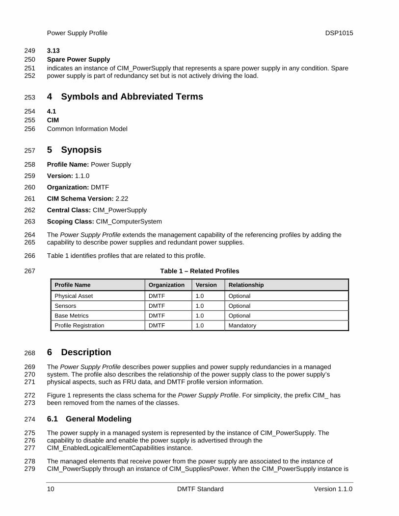
Table 1 identifies profiles that are related to this profile.
Table 1 – Related Profiles
Profile Name Organization Version Relationship
Physical Asset DMTF 1.0 Optional
Sensors DMTF 1.0 Optional
Base Metrics DMTF 1.0 Optional
Profile Registration DMTF 1.0 Mandatory
6 Description 268
The Power Supply Profile describes power supplies and power supply redundancies in a managed system. The profile also describes the relationship of the power supply class to the power supply’s physical aspects, such as FRU data, and DMTF profile version information.
269 270 271
272 273
275 276 277
278 279
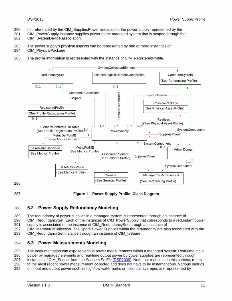
Figure 1 represents the class schema for the Power Supply Profile. For simplicity, the prefix CIM_ has been removed from the names of the classes.
6.1 General Modeling 274
The power supply in a managed system is represented by the instance of CIM_PowerSupply. The capability to disable and enable the power supply is advertised through the CIM_EnabledLogicalElementCapabilities instance.
The managed elements that receive power from the power supply are associated to the instance of CIM_PowerSupply through an instance of CIM_SuppliesPower. When the CIM_PowerSupply instance is
DSP1015 Power Supply Profile
280 281 282
283 284
285
not referenced by the CIM_SuppliesPower association, the power supply represented by the CIM_PowerSupply instance supplies power to the managed system that is scoped through the CIM_SystemDevice association.
The power supply’s physical aspects can be represented by one or more instances of CIM_PhysicalPackage.
The profile information is represented with the instance of CIM_RegisteredProfile.
ComputerSystem
(See Referencing Profile)
PowerSupply
MemberOfCollection
RedundancySet
PhysicalPackage(See Physical Asset Profile)RegisteredProfile
(See Profile Registration Profile)
ElementConformsToProfile(See Profile Registration Profile)
1..*
0..1 1
*
1..*
SystemDeviceIsSpare
1..*
0..1
Version 1.1.0 DMTF Standard 11
ManagedSystemElement
SuppliesPower
*
*
EnabledLogicalElementCapabilities
Ele
men
tCap
abili
ties
0..1
1..*
0..1
1..*
OwningCollectionElement1*
*Sensor
(See Sensors Profile) (See Referencing Profile)
BaseMetricDefinition(See Metrics Profile)
BaseMetricValue(See Metrics Profile)
Associated Sensor(See Sensors Profile)
MetricForME(See Metrics Profile)
MetricDefForME(See Metrics Profile)
1
*
1
1
*
Realizes(See Physical Asset Profile)
*
AdminDomain
SuppliesPower
SystemComponent0..1
*
*
SystemComponent
*
*
1
SystemComponent0..1
*
286
287
289 290 291 292 293
295 296
Figure 1 – Power Supply Profile: Class Diagram
6.2 Power Supply Redundancy Modeling 288
The redundancy of power supplies in a managed system is represented through an instance of CIM_RedundancySet. Each of the instances of CIM_PowerSupply that corresponds to a redundant power supply is associated to the instance of CIM_RedundancySet through an instance of CIM_MemberOfCollection. The Spare Power Supplies within the redundancy are also associated with the CIM_RedundancySet instance through an instance of CIM_IsSpare.
6.3 Power Measurements Modeling 294
The instrumentation can expose various power measurements within a managed system. Real-time input power by managed elements and real-time output power by power supplies are represented through instances of CIM_Sensor from the Sensors Profile (DSP1009). Note that real-time, in this context, refers to the most recent power measurement collected and does not have to be instantaneous. Various metrics on input and output power such as high/low watermarks or historical averages are represented by
297 298 299
Power Supply Profile DSP1015
12 DMTF Standard Version 1.1.0
instances of CIM_BaseMetricDefinition and CIM_BaseMetricValue from the Base Metrics Profile. (
300 DSP1053) 301
303 304
306
308 309 310 311
312 313
315 316 317 318 319 320
322 323
325 326
328 329
331 332 333 334
336 337
7 Implementation Requirements 302
Requirements and guidelines for propagating and formulating certain properties of the classes are discussed in this section. Methods are listed in section 8 and properties are listed in section 10.
7.1 CIM_PowerSupply 305
Zero or more instances of CIM_PowerSupply shall be instantiated.
7.2 CIM_EnabledLogicalElementCapabilities 307
If the CIM_EnabledLogicalElementCapabilities class is instantiated, the instance of CIM_EnabledLogicalElementCapabilities shall be associated with the CIM_PowerSupply instance through an instance of CIM_ElementCapabilities and used for advertising the capabilities of the CIM_PowerSupply instance.
There shall be at most one instance of CIM_EnabledLogicalElementCapabilities associated with a given instance of CIM_PowerSupply.
7.2.1 CIM_EnabledLogicalElementCapabilities.RequestedStatesSupported 314
CIM_EnabledLogicalElementCapabilities.RequestedStatesSupported is an array that contains the supported requested states for the instance of CIM_PowerSupply. This property shall be the complete set of the allowable values to be used as the RequestedState parameter in the RequestStateChange( ) method (see section 8.1). The value of the CIM_EnabledLogicalElementCapabilities.RequestedStatesSupported property shall be an empty array or contain any combination of the following values: 2 (Enabled), 3 (Disabled), 6 (Offline), or 11 (Reset).
7.2.2 CIM_EnabledLogicalElementCapabilities.ElementNameEditSupported 321
This property shall have a value of TRUE if the implementation supports client modification of the CIM_PowerSupply.ElementName property.
7.2.3 CIM_EnabledLogicalElementCapabilities.MaxElementNameLen 324
The MaxElementNameLen property shall be implemented if the ElementNameEditSupported property has a value of TRUE.
7.2.4 CIM_EnabledLogicalElementCapabilities.ElementNameMask 327
The ElementNameMask property shall be implemented if the ElementNameEditSupported property has a value of TRUE.
7.3 Power Supply State Management 330
The power supply state management defines the requirements for changing the enabled state of power supplies utilizing CIM_PowerSupply.RequestStateChange( ) method (see section 8.1). This section describes the detailed requirements for advertising and supporting power state management. If the power state management is supported, the requirements specified in this clause shall be met.
7.3.1 Power Supply State Management Support 335
If no CIM_EnabledLogicalElementCapabilities instance is associated with the CIM_PowerSupply instance, the power supply state management shall not be supported.

DSP1015 Power Supply Profile
Version 1.1.0 DMTF Standard 13
If a CIM_EnabledLogicalElementCapabilities instance is associated with the CIM_PowerSupply instance but the value of the CIM_EnabledLogicalElementCapabilities.RequestedStatesSupported property is an empty array, the power supply state management shall not be supported.
338 339 340
341 342 343
345 346 347 348
349 350 351 352 353 354
356 357
359 360 361
362 363 364
366 367 368 369 370 371
372
If a CIM_EnabledLogicalElementCapabilities instance is associated with the CIM_PowerSupply instance and the value of the CIM_EnabledLogicalElementCapabilities.RequestedStatesSupported property is not an empty array, the power supply state management shall be supported.
7.4 CIM_PowerSupply.RequestedState 344
The CIM_PowerSupply.RequestedState property shall have a value of 12 (Not Applicable), 5 (No Change), or a value contained in the CIM_EnabledLogicalElementCapabilities.RequestedStatesSupported property array of the associated CIM_EnabledLogicalElementCapabilities instance (see section 7.2.1).
If the power supply state management is supported and the RequestStateChange( ) method is successfully executed, the RequestedState property shall be set to the value of the parameter RequestedState of RequestStateChange( ) method. After the RequestStateChange( ) method has successfully executed, RequestedState and EnabledState shall have equal values with the exception of the transitional requested state 11 (Reset). The value of the RequestedState property may also change as a result of a request for change to the power supply’s enabled state by non-CIM implementation.
7.4.1 RequestedState — 12 (Not Applicable) Value 355
If the power supply state management is not supported, the value of the CIM_PowerSupply.RequestedState property shall be 12 (Not Applicable).
7.4.2 RequestedState — 5 (No Change) Value 358
The value 5 (No Change) for the RequestedState property shall only be used if the power supply state management instrumentation has not been invoked and thus the previous requested state cannot be determined.
If the power supply state management is supported, the initial value of the CIM_PowerSupply.RequestedState property shall be 5 (No Change) or shall match the previous requested state.
7.5 CIM_PowerSupply.EnabledState 365
Table 2 describes the mapping between the values of the CIM_PowerSupply.EnabledState property and the corresponding description of the state of the power supply. The CIM_PowerSupply.EnabledState property shall match the values that are specified in Table 2. If the RequestStateChange( ) method executes but does not complete successfully, and the power supply is in an indeterminate state, the CIM_PowerSupply.EnabledState property shall have value of 5 (Unknown). The value of this property may also change as a result of a change to the power supply’s enabled state by non-CIM implementation.
Table 2 – EnabledState Value Description
Value Description Extended Description
2 Enabled Power supply shall be enabled.
3 Disabled Power supply shall be disabled.
5 Not Applicable Power supply state is indeterminate, or the power supply state management is not supported.
6 Enabled but Offline Power supply shall be enabled but shall not actively supply power (used in redundant configuration; see section 7.7).
Power Supply Profile DSP1015
14 DMTF Standard Version 1.1.0
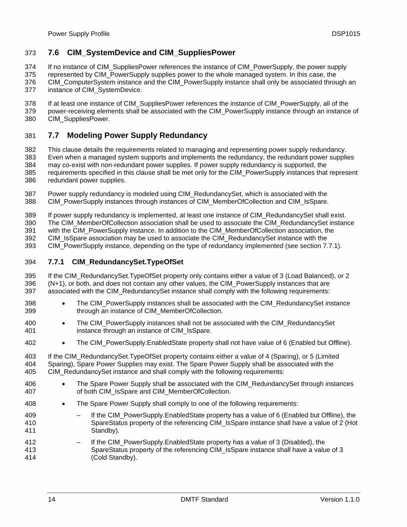
7.6 CIM_SystemDevice and CIM_SuppliesPower 373
If no instance of CIM_SuppliesPower references the instance of CIM_PowerSupply, the power supply represented by CIM_PowerSupply supplies power to the whole managed system. In this case, the CIM_ComputerSystem instance and the CIM_PowerSupply instance shall only be associated through an instance of CIM_SystemDevice.
374 375 376 377
378 379 380
382 383 384 385 386
387 388
389 390 391 392 393
395 396 397
398 399
400 401
402
403 404 405
406 407
408
409 410 411
412 413 414
If at least one instance of CIM_SuppliesPower references the instance of CIM_PowerSupply, all of the power-receiving elements shall be associated with the CIM_PowerSupply instance through an instance of CIM_SuppliesPower.
7.7 Modeling Power Supply Redundancy 381
This clause details the requirements related to managing and representing power supply redundancy. Even when a managed system supports and implements the redundancy, the redundant power supplies may co-exist with non-redundant power supplies. If power supply redundancy is supported, the requirements specified in this clause shall be met only for the CIM_PowerSupply instances that represent redundant power supplies.
Power supply redundancy is modeled using CIM_RedundancySet, which is associated with the CIM_PowerSupply instances through instances of CIM_MemberOfCollection and CIM_IsSpare.
If power supply redundancy is implemented, at least one instance of CIM_RedundancySet shall exist. The CIM_MemberOfCollection association shall be used to associate the CIM_RedundancySet instance with the CIM_PowerSupply instance. In addition to the CIM_MemberOfCollection association, the CIM_IsSpare association may be used to associate the CIM_RedundancySet instance with the CIM_PowerSupply instance, depending on the type of redundancy implemented (see section 7.7.1).
7.7.1 CIM_RedundancySet.TypeOfSet 394
If the CIM_RedundancySet.TypeOfSet property only contains either a value of 3 (Load Balanced), or 2 (N+1), or both, and does not contain any other values, the CIM_PowerSupply instances that are associated with the CIM_RedundancySet instance shall comply with the following requirements:
• The CIM_PowerSupply instances shall be associated with the CIM_RedundancySet instance through an instance of CIM_MemberOfCollection.
• The CIM_PowerSupply instances shall not be associated with the CIM_RedundancySet instance through an instance of CIM_IsSpare.
• The CIM_PowerSupply.EnabledState property shall not have value of 6 (Enabled but Offline).
If the CIM_RedundancySet.TypeOfSet property contains either a value of 4 (Sparing), or 5 (Limited Sparing), Spare Power Supplies may exist. The Spare Power Supply shall be associated with the CIM_RedundancySet instance and shall comply with the following requirements:
• The Spare Power Supply shall be associated with the CIM_RedundancySet through instances of both CIM_IsSpare and CIM_MemberOfCollection.
• The Spare Power Supply shall comply to one of the following requirements:
– If the CIM_PowerSupply.EnabledState property has a value of 6 (Enabled but Offline), the SpareStatus property of the referencing CIM_IsSpare instance shall have a value of 2 (Hot Standby).
– If the CIM_PowerSupply.EnabledState property has a value of 3 (Disabled), the SpareStatus property of the referencing CIM_IsSpare instance shall have a value of 3 (Cold Standby).
DSP1015 Power Supply Profile
Version 1.1.0 DMTF Standard 15
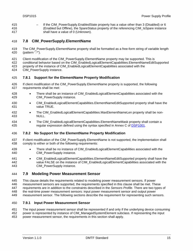
– If the CIM_PowerSupply.EnabledState property has a value other than 3 (Disabled) or 6 (Enabled but Offline), the SpareStatus property of the referencing CIM_IsSpare instance shall have a value of 0 (Unknown).
415 416 417
419 420
421 422 423 424
426 427
428 429
430 431
432 433
434
7.8 CIM_PowerSupply.ElementName 418
The CIM_PowerSupply.ElementName property shall be formatted as a free-form string of variable length (pattern “.*”).
Client modification of the CIM_PowerSupply.ElementName property may be supported. This is conditional behavior based on the CIM_EnabledLogicalElementCapabilities.ElementNameEditSupported property of the instance of CIM_EnabledLogicalElementCapabilities associated with the CIM_PowerSupply instance.
7.8.1 Support for the ElementName Property Modification 425
If client modification of the CIM_PowerSupply.ElementName property is supported, the following requirements shall be met:
• There shall be an instance of CIM_EnabledLogicalElementCapabilities associated with the CIM_PowerSupply instance.
• CIM_EnabledLogicalElementCapabilities.ElementNameEditSupported property shall have the value TRUE.
• The CIM_EnabledLogicalElementCapabilities.MaxElementNameLen property shall be non-NULL.
• The CIM_EnabledLogicalElementCapabilities.ElementNameMask property shall contain a regular expression defined using the syntax specified in Annex C of DSP1001. 435
437 438
439 440
441 442 443
445 446 447 448 449
451 452 453
7.8.2 No Support for the ElementName Property Modification 436
If client modification of the CIM_PowerSupply.ElementName is not supported, the implementation shall comply to either or both of the following requirements:
• There shall be no instance of CIM_EnabledLogicalElementCapabilities associated with the CIM_PowerSupply instance.
• CIM_EnabledLogicalElementCapabilities.ElementNameEditSupported property shall have the value FALSE on the instance of CIM_EnabledLogicalElementCapabilities associated with the CIM_PowerSupply instance.
7.9 Modeling Power Measurement Sensor 444
This clause details the requirements related to modeling power measurement sensors. If power measurement sensors are supported, the requirements specified in this clause shall be met. These requirements are in addition to the constraints described in the Sensors Profile. There are two types of the real-time power measurement sensors: input power measurement sensor and output power measurement sensor. The following sections describe the requirement for representing such sensors.
7.9.1 Input Power Measurement Sensor 450
The input power measurement sensor shall be represented if and only if the underlying device consuming power is represented by instance of CIM_ManagedSystemElement subclass. If representing the input power measurement sensor, the requirements in this section shall apply.
Power Supply Profile DSP1015
16 DMTF Standard Version 1.1.0
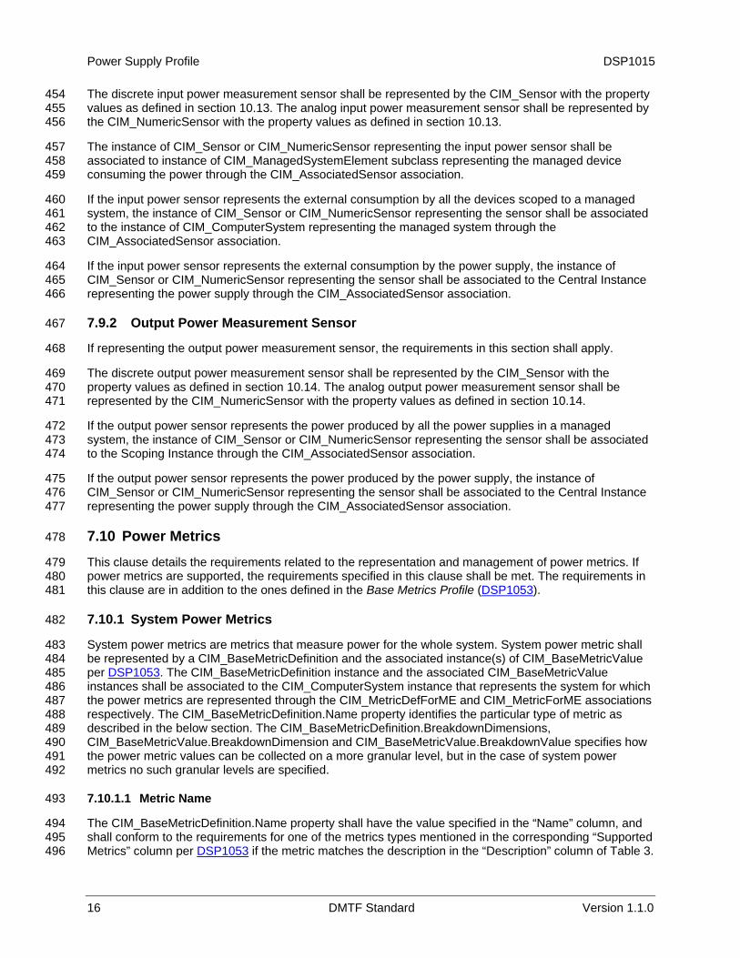
The discrete input power measurement sensor shall be represented by the CIM_Sensor with the property values as defined in section
454 455 456
457 458 459
460 461 462 463
464 465 466
468
469 470 471
472 473 474
475 476 477
479 480
10.13. The analog input power measurement sensor shall be represented by the CIM_NumericSensor with the property values as defined in section 10.13.
The instance of CIM_Sensor or CIM_NumericSensor representing the input power sensor shall be associated to instance of CIM_ManagedSystemElement subclass representing the managed device consuming the power through the CIM_AssociatedSensor association.
If the input power sensor represents the external consumption by all the devices scoped to a managed system, the instance of CIM_Sensor or CIM_NumericSensor representing the sensor shall be associated to the instance of CIM_ComputerSystem representing the managed system through the CIM_AssociatedSensor association.
If the input power sensor represents the external consumption by the power supply, the instance of CIM_Sensor or CIM_NumericSensor representing the sensor shall be associated to the Central Instance representing the power supply through the CIM_AssociatedSensor association.
7.9.2 Output Power Measurement Sensor 467
If representing the output power measurement sensor, the requirements in this section shall apply.
The discrete output power measurement sensor shall be represented by the CIM_Sensor with the property values as defined in section 10.14. The analog output power measurement sensor shall be represented by the CIM_NumericSensor with the property values as defined in section 10.14.
If the output power sensor represents the power produced by all the power supplies in a managed system, the instance of CIM_Sensor or CIM_NumericSensor representing the sensor shall be associated to the Scoping Instance through the CIM_AssociatedSensor association.
If the output power sensor represents the power produced by the power supply, the instance of CIM_Sensor or CIM_NumericSensor representing the sensor shall be associated to the Central Instance representing the power supply through the CIM_AssociatedSensor association.
7.10 Power Metrics 478
This clause details the requirements related to the representation and management of power metrics. If power metrics are supported, the requirements specified in this clause shall be met. The requirements in this clause are in addition to the ones defined in the Base Metrics Profile (DSP1053). 481
483 484
7.10.1 System Power Metrics 482
System power metrics are metrics that measure power for the whole system. System power metric shall be represented by a CIM_BaseMetricDefinition and the associated instance(s) of CIM_BaseMetricValue per DSP1053. The CIM_BaseMetricDefinition instance and the associated CIM_BaseMetricValue instances shall be associated to the CIM_ComputerSystem instance that represents the system for which the power metrics are represented through the CIM_MetricDefForME and CIM_MetricForME associations respectively. The CIM_BaseMetricDefinition.Name property identifies the particular type of metric as described in the below section. The CIM_BaseMetricDefinition.BreakdownDimensions, CIM_BaseMetricValue.BreakdownDimension and CIM_BaseMetricValue.BreakdownValue specifies how the power metric values can be collected on a more granular level, but in the case of system power metrics no such granular levels are specified.
485 486 487 488 489 490 491 492
494 495
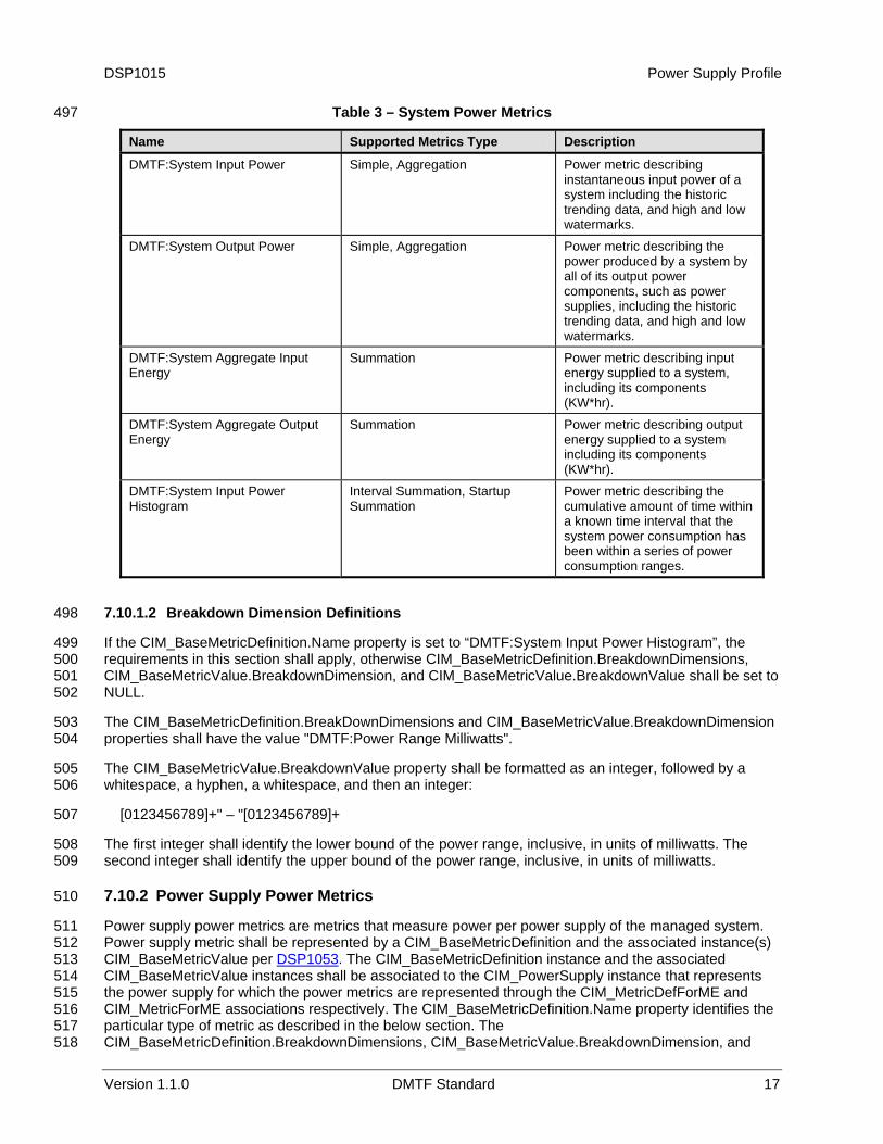
7.10.1.1 Metric Name 493
The CIM_BaseMetricDefinition.Name property shall have the value specified in the “Name” column, and shall conform to the requirements for one of the metrics types mentioned in the corresponding “Supported Metrics” column per DSP1053 if the metric matches the description in the “Description” column of Table 3. 496
DSP1015 Power Supply Profile
Version 1.1.0 DMTF Standard 17
Table 3 – System Power Metrics 497
Name Supported Metrics Type Description
DMTF:System Input Power Simple, Aggregation Power metric describing instantaneous input power of a system including the historic trending data, and high and low watermarks.
DMTF:System Output Power Simple, Aggregation Power metric describing the power produced by a system by all of its output power components, such as power supplies, including the historic trending data, and high and low watermarks.
DMTF:System Aggregate Input Energy
Summation Power metric describing input energy supplied to a system, including its components (KW*hr).
DMTF:System Aggregate Output Energy
Summation Power metric describing output energy supplied to a system including its components (KW*hr).
DMTF:System Input Power Histogram
Interval Summation, Startup Summation
Power metric describing the cumulative amount of time within a known time interval that the system power consumption has been within a series of power consumption ranges.
7.10.1.2 Breakdown Dimension Definitions 498
If the CIM_BaseMetricDefinition.Name property is set to “DMTF:System Input Power Histogram”, the requirements in this section shall apply, otherwise CIM_BaseMetricDefinition.BreakdownDimensions, CIM_BaseMetricValue.BreakdownDimension, and CIM_BaseMetricValue.BreakdownValue shall be set to NULL.
499 500 501 502
503 504
505 506
507
508 509
511 512
The CIM_BaseMetricDefinition.BreakDownDimensions and CIM_BaseMetricValue.BreakdownDimension properties shall have the value "DMTF:Power Range Milliwatts".
The CIM_BaseMetricValue.BreakdownValue property shall be formatted as an integer, followed by a whitespace, a hyphen, a whitespace, and then an integer:
[0123456789]+" – "[0123456789]+
The first integer shall identify the lower bound of the power range, inclusive, in units of milliwatts. The second integer shall identify the upper bound of the power range, inclusive, in units of milliwatts.
7.10.2 Power Supply Power Metrics 510
Power supply power metrics are metrics that measure power per power supply of the managed system. Power supply metric shall be represented by a CIM_BaseMetricDefinition and the associated instance(s) CIM_BaseMetricValue per DSP1053. The CIM_BaseMetricDefinition instance and the associated CIM_BaseMetricValue instances shall be associated to the CIM_PowerSupply instance that represents the power supply for which the power metrics are represented through the CIM_MetricDefForME and CIM_MetricForME associations respectively. The CIM_BaseMetricDefinition.Name property identifies the particular type of metric as described in the below section. The CIM_BaseMetricDefinition.BreakdownDimensions, CIM_BaseMetricValue.BreakdownDimension, and
513 514 515 516 517 518
Power Supply Profile DSP1015
18 DMTF Standard Version 1.1.0
CIM_BaseMetricValue.BreakdownValue properties specify how the power metric values can be collected on a more granular level, as described in
519 520
522 523
7.10.2.2.
7.10.2.1 CIM_BaseMetricDefinition.Name 521
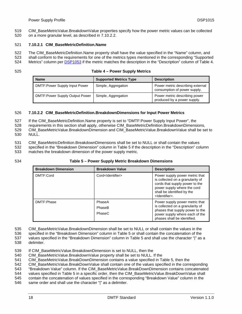
The CIM_BaseMetricDefinition.Name property shall have the value specified in the “Name” column, and shall conform to the requirements for one of the metrics types mentioned in the corresponding “Supported Metrics” column per DSP1053 if the metric matches the description in the “Description” column of Table 4. 524
525 Table 4 – Power Supply Metrics
Name Supported Metrics Type Description
DMTF:Power Supply Input Power Simple, Aggregation Power metric describing external consumption of power supply.
DMTF:Power Supply Output Power Simple, Aggregation Power metric describing power produced by a power supply.
7.10.2.2 CIM_BaseMetricDefinition.BreakdownDimensions for Input Power Metrics 526
If the CIM_BaseMetricDefinition.Name property is set to “DMTF:Power Supply Input Power”, the requirements in this section shall apply, otherwise CIM_BaseMetricDefinition.BreakdownDimensions, CIM_BaseMetricValue.BreakdownDimension and CIM_BaseMetricValue.BreakdownValue shall be set to NULL.
527 528 529 530
531 532 533
534
CIM_BaseMetricDefinition.BreakdownDimensions shall be set to NULL or shall contain the values specified in the “Breakdown Dimension” column in Table 5 if the description in the “Description” column matches the breakdown dimension of the power supply metric.
Table 5 – Power Supply Metric Breakdown Dimensions
Breakdown Dimension Breakdown Value Description
DMTF:Cord Cord<Identifier> Power supply power metric that is collected on a granularity of cords that supply power to the power supply where the cord shall be identified by the <Identifier>.
DMTF:Phase PhaseA PhaseB PhaseC
Power supply power metric that is collected on a granularity of phases that supply power to the power supply where each of the phases shall be identified.
CIM_BaseMetricValue.BreakdownDimension shall be set to NULL or shall contain the values in the specified in the “Breakdown Dimension” column in
535 536 537 538
539 540 541 542 543 544 545 546
Table 5 or shall contain the concatenation of the values specified in the “Breakdown Dimension” column in Table 5 and shall use the character “|” as a delimiter.
If CIM_BaseMetricValue.BreakdownDimension is set to NULL, then the CIM_BaseMetricValue.BreakdownValue property shall be set to NULL. If the CIM_BaseMetricValue.BreakDownDimension contains a value specified in Table 5, then the CIM_BaseMetricValue.BreakDownValue shall contain one of the values specified in the corresponding “Breakdown Value” column. If the CIM_BaseMetricValue.BreakDownDimension contains concatenated values specified in Table 5 in a specific order, then the CIM_BaseMetricValue.BreakDownValue shall contain the concatenation of values specified in the corresponding “Breakdown Value” column in the same order and shall use the character “|” as a delimiter.
DSP1015 Power Supply Profile
Version 1.1.0 DMTF Standard 19
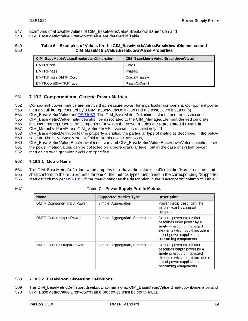
Examples of allowable values of CIM_BaseMetricValue.BreakdownDimension and CIM_BaseMetricValue.BreakdownValue are detailed in
547 548
549 550
Table 6.
Table 6 – Examples of Values for the CIM_BaseMetricValue.BreakdownDimension and CIM_BaseMetricValue.BreakdownValue Properties
CIM_BaseMetricValue.BreakdownDimension CIM_BaseMetricValue.BreakdownValue
DMTF:Cord Cord1
DMTF:Phase PhaseB
DMTF:Phase|DMTF:Cord Cord2|PhaseA
DMTF:Cord|DMTF:Phase PhaseC|Cord1
7.10.3 Component and Generic Power Metrics 551
Component power metrics are metrics that measure power for a particular component. Component power metric shall be represented by a CIM_BaseMetricDefinition and the associated instance(s) CIM_BaseMetricValue per
552 553
DSP1053. The CIM_BaseMetricDefinition instance and the associated CIM_BaseMetricValue instances shall be associated to the CIM_ManagedElement derived concrete instance that represents the component for which the power metrics are represented through the CIM_MetricDefForME and CIM_MetricForME associations respectively. The CIM_BaseMetricDefinition.Name property identifies the particular type of metric as described in the below section. The CIM_BaseMetricDefinition.BreakdownDimensions, CIM_BaseMetricValue.BreakdownDimension and CIM_BaseMetricValue.BreakdownValue specifies how the power metric values can be collected on a more granular level, but in the case of system power metrics no such granular levels are specified.
554 555 556 557 558 559 560 561 562
564 565
7.10.3.1 Metric Name 563
The CIM_BaseMetricDefinition.Name property shall have the value specified in the “Name” column, and shall conform to the requirements for one of the metrics types mentioned in the corresponding “Supported Metrics” column per DSP1053 if the metric matches the description in the “Description” column of Table 7. 566
567 Table 7 – Power Supply Profile Metrics
Name Supported Metrics Type Description
DMTF:Component Input Power Simple, Aggregation Power metric describing the input power by a specific component.
DMTF:Generic Input Power Simple, Aggregation, Summation Generic power metric that describes input power by a single or group of managed elements which could include a mix of power supplies and consuming components.
DMTF:Generic Output Power Simple, Aggregation, Summation Generic power metric that describes output power by a single or group of managed elements which could include a mix of power supplies and consuming components.
7.10.3.2 Breakdown Dimension Definitions 568
The CIM_BaseMetricDefinition.BreakdownDimensions, CIM_BaseMetricValue.BreakdownDimension and CIM_BaseMetricValue.BreakdownValue properties shall be set to NULL.
569 570

Power Supply Profile DSP1015
20 DMTF Standard Version 1.1.0
8 Methods 571
This section details the requirements for supporting intrinsic operations and extrinsic methods for the CIM elements defined by this profile.
572 573
575 576
577 578 579
580 581
582 583
584 585
586
587
8.1 Method: CIM_PowerSupply.RequestStateChange( ) 574
Invocation of the CIM_PowerSupply.RequestStateChange( ) method will change the element’s state to the value that is specified in the RequestedState parameter.
Return values for RequestStateChange( ) shall be as specified in Table 8 where the method-execution behavior matches the return-code description. RequestStateChange( ) method’s parameters are specified in Table 9.
If the power supply state management is supported, the RequestStateChange( ) method shall be implemented and shall not return a value of 1 (Not Supported) (see section 7.3.1).
If the value of the RequestedState parameter is 6 (Offline) and the power supply is not a Spare Power Supply, the RequestStateChange( ) method shall return a value of 2 (Error Occurred).
Invoking the CIM_PowerSupply.RequestStateChange( ) method multiple times could result in earlier requests being overwritten or lost.
No standard messages are defined for this method.
Table 8 – CIM_PowerSupply.RequestStateChange( ) Method: Return Code Values
Value Description
0 Request was successfully executed.
1 Method is not supported in the implementation.
2 Error occurred
4096 Job started
Table 9 – CIM_PowerSupply.RequestStateChange( ) Method: Parameters 588
Qualifiers Name Type Description/Values
IN, REQ RequestedState uint16 Valid state values: 2 (Enabled) 3 (Disabled) (see section 8.1.1) 6 (Offline) (see section 8.1.1) 11 (Reset)
OUT Job CIM_ConcreteJob REF Returned if job started
IN, REQ TimeoutPeriod Datetime Client specified maximum amount of time the transition to a new state is supposed to take: 0 or NULL – No time requirements <interval> – Maximum time allowed
8.1.1 RequestStateChange( ) for a Spare Power Supply 589
After the successful execution of the RequestStateChange( ) method on a Spare Power Supply with the RequestedState parameter set to 6 (Offline), the SpareStatus of the referenced CIM_IsSpare association shall have value of 2 (Hot Standby).
590 591 592
DSP1015 Power Supply Profile
Version 1.1.0 DMTF Standard 21
After the successful execution of the RequestStateChange( ) method on a Spare Power Supply with the RequestedState parameter set to 3 (Disabled), the SpareStatus of the referenced CIM_IsSpare association shall have value of 3 (Cold Standby).
593 594 595
597 598 599 600 601
602 603 604
605 606
607 608
609 610
611 612 613
614
615 616 617 618
619 620
621 622 623
624 625
626
627
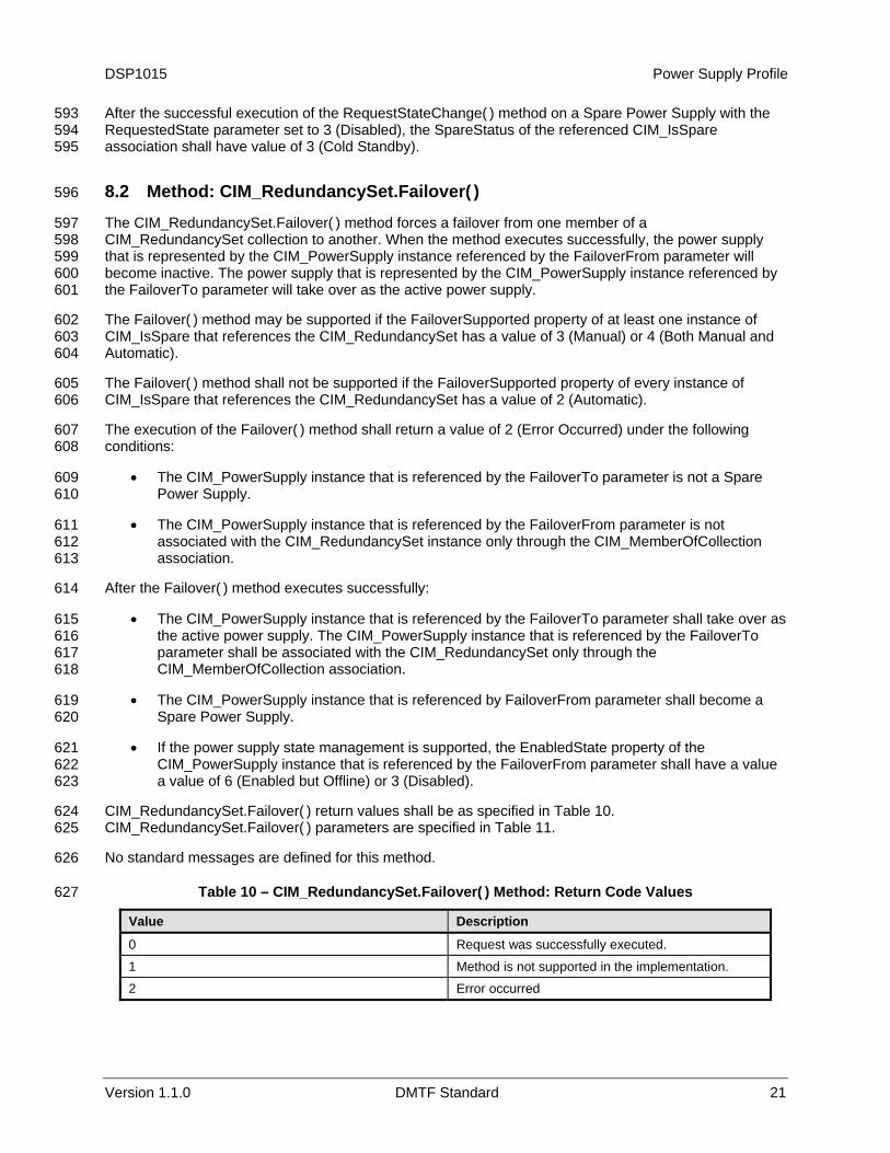
8.2 Method: CIM_RedundancySet.Failover( ) 596
The CIM_RedundancySet.Failover( ) method forces a failover from one member of a CIM_RedundancySet collection to another. When the method executes successfully, the power supply that is represented by the CIM_PowerSupply instance referenced by the FailoverFrom parameter will become inactive. The power supply that is represented by the CIM_PowerSupply instance referenced by the FailoverTo parameter will take over as the active power supply.
The Failover( ) method may be supported if the FailoverSupported property of at least one instance of CIM_IsSpare that references the CIM_RedundancySet has a value of 3 (Manual) or 4 (Both Manual and Automatic).
The Failover( ) method shall not be supported if the FailoverSupported property of every instance of CIM_IsSpare that references the CIM_RedundancySet has a value of 2 (Automatic).
The execution of the Failover( ) method shall return a value of 2 (Error Occurred) under the following conditions:
• The CIM_PowerSupply instance that is referenced by the FailoverTo parameter is not a Spare Power Supply.
• The CIM_PowerSupply instance that is referenced by the FailoverFrom parameter is not associated with the CIM_RedundancySet instance only through the CIM_MemberOfCollection association.
After the Failover( ) method executes successfully:
• The CIM_PowerSupply instance that is referenced by the FailoverTo parameter shall take over as the active power supply. The CIM_PowerSupply instance that is referenced by the FailoverTo parameter shall be associated with the CIM_RedundancySet only through the CIM_MemberOfCollection association.
• The CIM_PowerSupply instance that is referenced by FailoverFrom parameter shall become a Spare Power Supply.
• If the power supply state management is supported, the EnabledState property of the CIM_PowerSupply instance that is referenced by the FailoverFrom parameter shall have a value a value of 6 (Enabled but Offline) or 3 (Disabled).
CIM_RedundancySet.Failover( ) return values shall be as specified in Table 10. CIM_RedundancySet.Failover( ) parameters are specified in Table 11.
No standard messages are defined for this method.
Table 10 – CIM_RedundancySet.Failover( ) Method: Return Code Values
Value Description
0 Request was successfully executed.
1 Method is not supported in the implementation.
2 Error occurred
Power Supply Profile DSP1015
22 DMTF Standard Version 1.1.0
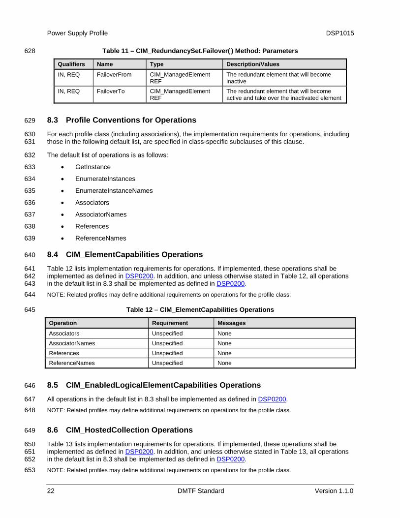
Table 11 – CIM_RedundancySet.Failover( ) Method: Parameters 628
Qualifiers Name Type Description/Values
IN, REQ FailoverFrom CIM_ManagedElement REF
The redundant element that will become inactive
IN, REQ FailoverTo CIM_ManagedElement REF
The redundant element that will become active and take over the inactivated element
8.3 Profile Conventions for Operations 629
For each profile class (including associations), the implementation requirements for operations, including those in the following default list, are specified in class-specific subclauses of this clause.
630 631
632
633
634
635
636
637
638
639
641
The default list of operations is as follows:
• GetInstance
• EnumerateInstances
• EnumerateInstanceNames
• Associators
• AssociatorNames
• References
• ReferenceNames
8.4 CIM_ElementCapabilities Operations 640
Table 12 lists implementation requirements for operations. If implemented, these operations shall be implemented as defined in DSP0200. In addition, and unless otherwise stated in Table 12, all operations in the default list in
642 8.3 shall be implemented as defined in DSP0200. 643
644
645
NOTE: Related profiles may define additional requirements on operations for the profile class.
Table 12 – CIM_ElementCapabilities Operations
Operation Requirement Messages
Associators Unspecified None
AssociatorNames Unspecified None
References Unspecified None
ReferenceNames Unspecified None
8.5 CIM_EnabledLogicalElementCapabilities Operations 646
All operations in the default list in 8.3 shall be implemented as defined in DSP0200. 647 648
650
NOTE: Related profiles may define additional requirements on operations for the profile class.
8.6 CIM_HostedCollection Operations 649
Table 13 lists implementation requirements for operations. If implemented, these operations shall be implemented as defined in DSP0200. In addition, and unless otherwise stated in Table 13, all operations in the default list in
651 8.3 shall be implemented as defined in DSP0200. 652
653 NOTE: Related profiles may define additional requirements on operations for the profile class.
DSP1015 Power Supply Profile
Version 1.1.0 DMTF Standard 23
Table 13 – CIM_HostedCollection Operations 654
Operation Requirement Messages
Associators Unspecified None
AssociatorNames Unspecified None
References Unspecified None
ReferenceNames Unspecified None
8.7 CIM_IsSpare Operations 655
Table 14 lists implementation requirements for operations. If implemented, these operations shall be implemented as defined in
656 DSP0200. In addition, and unless otherwise stated in Table 14, all operations
in the default list in 657
8.3 shall be implemented as defined in DSP0200. 658 659
660
NOTE: Related profiles may define additional requirements on operations for the profile class.
Table 14 – CIM_IsSpare Operations
Operation Requirement Messages
Associators Unspecified None
AssociatorNames Unspecified None
References Unspecified None
ReferenceNames Unspecified None
8.8 CIM_MemberOfCollection Operations 661
Table 15 lists implementation requirements for operations. If implemented, these operations shall be implemented as defined in
662 DSP0200. In addition, and unless otherwise stated in Table 15, all operations
in the default list in 663
8.3 shall be implemented as defined in DSP0200. 664 665
666
NOTE: Related profiles may define additional requirements on operations for the profile class.
Table 15 – CIM_MemberOfCollection Operations
Operation Requirement Messages
Associators Unspecified None
AssociatorNames Unspecified None
References Unspecified None
ReferenceNames Unspecified None
8.9 CIM_OwningCollectionElement Operations 667
Table 16 lists implementation requirements for operations. If implemented, these operations shall be implemented as defined in
668 DSP0200. In addition, and unless otherwise stated in Table 16, all operations
in the default list in 669
8.3 shall be implemented as defined in DSP0200. 670 671 NOTE: Related profiles may define additional requirements on operations for the profile class.
Power Supply Profile DSP1015
24 DMTF Standard Version 1.1.0
Table 16 – CIM_OwningCollectionElement Operations 672
Operation Requirement Messages
Associators Unspecified None
AssociatorNames Unspecified None
References Unspecified None
ReferenceNames Unspecified None
8.10 CIM_PowerSupply Operations 673
Table 17 lists implementation requirements for operations. If implemented, these operations shall be implemented as defined in
674 DSP0200. In addition, and unless otherwise stated in Table 17, all operations
in the default list in 675
8.3 shall be implemented as defined in DSP0200. 676 677
678
NOTE: Related profiles may define additional requirements on operations for the profile class.
Table 17 – CIM_PowerSupply Operations
Operation Requirement Messages
ModifyInstance Optional. See section 8.10.1. None
8.10.1 CIM_PowerSupply — ModifyInstance 679
This section details the requirements for the ModifyInstance operation applied to an instance of CIM_PowerSupply. The ModifyInstance operation may be supported.
680 681
682 683 684 685
687 688 689 690 691
692 693 694
The ModifyInstance operation shall be supported and CIM_PowerSupply.ElementName shall be modifiable if the ElementNameEditSupported property of the CIM_EnabledLogicalElementCapabilities instance that is associated with the CIM_PowerSupply instance has a value of TRUE. See section 8.10.1.1.
8.10.1.1 CIM_PowerSupply.ElementName 686
If the ElementNameEditSupported property of the CIM_EnabledLogicalElementCapabilities instance that is associated with the CIM_PowerSupply instance has a value of TRUE, the implementation shall allow the ModifyInstance operation to change the value of the ElementName property of the CIM_PowerSupply instance. The ModifyInstance operation shall enforce the length restriction specified in the MaxElementNameLen property of the CIM_EnabledLogicalElementCapabilities instance.
If the ElementNameEditSupported property of the CIM_EnabledLogicalElementCapabilities instance has a value of FALSE, the implementation shall not allow the ModifyInstance operation to change the value of the ElementName property of the CIM_PowerSupply instance.
8.11 CIM_RedundancySet Operations 695
All operations in the default list in 8.3 shall be implemented as defined in DSP0200. 696 697
699
NOTE: Related profiles may define additional requirements on operations for the profile class.
8.12 CIM_SuppliesPower Operations 698
Table 18 lists implementation requirements for operations. If implemented, these operations shall be implemented as defined in DSP0200. In addition, and unless otherwise stated in Table 18, all operations in the default list in
700 8.3 shall be implemented as defined in DSP0200. 701
702 NOTE: Related profiles may define additional requirements on operations for the profile class.
DSP1015 Power Supply Profile
Version 1.1.0 DMTF Standard 25
Table 18 – CIM_SuppliesPower Operations 703
Operation Requirement Messages
Associators Unspecified None
AssociatorNames Unspecified None
References Unspecified None
ReferenceNames Unspecified None
8.13 CIM_SystemDevice Operations 704
Table 19 lists implementation requirements for operations. If implemented, these operations shall be implemented as defined in
705 DSP0200. In addition, and unless otherwise stated in Table 19, all operations
in the default list in 706
8.3 shall be implemented as defined in DSP0200. 707 708
709
NOTE: Related profiles may define additional requirements on operations for the profile class.
Table 19 – CIM_SystemDevice Operations
Operation Requirement Messages
Associators Unspecified None
AssociatorNames Unspecified None
References Unspecified None
ReferenceNames Unspecified None
9 Use Cases 710
This section contains object diagrams and use cases for the Power Supply Profile. 711
713 714 715 716
717 718 719 720 721 722
723
9.1 Object Diagrams 712
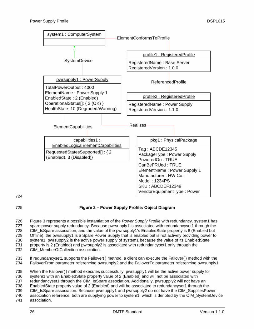
Figure 2 represents a possible instantiation of the Power Supply Profile. In this instantiation, the managed system, system1, has a power supply, pwrsupply1. The power supply is operating but in a degraded state. pwrsupply1 produces 4000 milliwatts of power. pwrsupply1’s physical package information is represented as well.
Because pwrsupply1 does not have the CIM_SuppliesPower association reference, pwrsupply1 is supplying power to system1, which is denoted by the CIM_SystemDevice association. system1 is also the scoping instance for pwrsupply1. Thus, following the CIM_ElementConformsToProfile association to profile1 and then the referenced CIM_ReferencedProfile association to a CIM_RegisteredProfile instance with the RegisteredName property set to “Power Supply”, the client can retrieve profile2. profile2 will show the version of the current Power Supply Profile implementation.
For simplicity, the prefix CIM_ has been removed from the names of the classes in the figure.
Power Supply Profile DSP1015
system1 : ComputerSystem
pwrsupply1 : PowerSupply
TotalPowerOutput : 4000ElementName : Power Supply 1EnabledState : 2 (Enabled)OperationalStatus[]: { 2 (OK) }HealthState: 10 (Degraded/Warning)
Realizes
pkg1 : PhysicalPackage
Tag : ABCDE12345PackageType : Power SupplyPoweredOn : TRUECanBeFRUed : TRUEElementName : Power Supply 1Manufacturer : HW Co.Model : 1234PSSKU : ABCDEF12349VendorEquipmentType : Power
profile1 : RegisteredProfile
RegisteredName : Base Server RegisteredVersion : 1.0.0
profile2 : RegisteredProfile
RegisteredName : Power Supply RegisteredVersion : 1.1.0
ReferencedProfile
ElementConformsToProfile
SystemDevice
capabilities1 : EnabledLogicalElementCapabilities
RequestedStatesSupported[] : { 2 (Enabled), 3 (Disabled)}
ElementCapabilities
724
725
726 727 728 729 730 731 732
733 734
735 736 737 738 739 740 741
Figure 2 – Power Supply Profile: Object Diagram
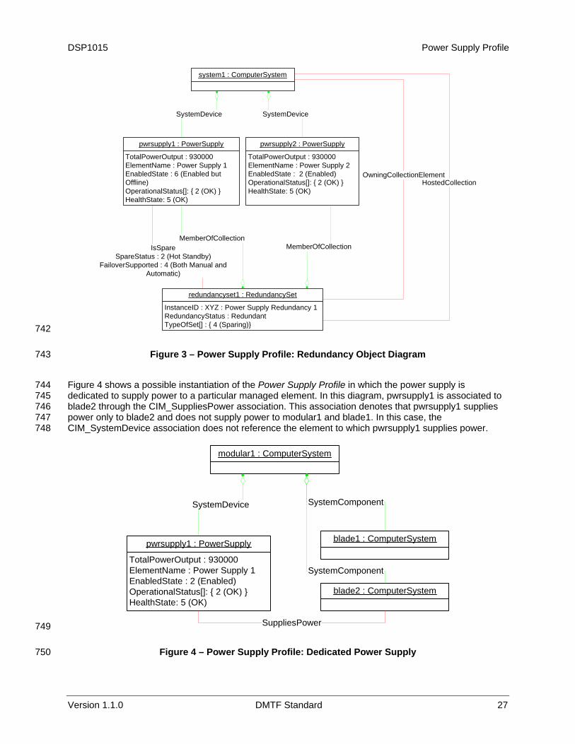
Figure 3 represents a possible instantiation of the Power Supply Profile with redundancy. system1 has spare power supply redundancy. Because pwrsupply1 is associated with redundancyset1 through the CIM_IsSpare association, and the value of the pwrsupply1’s EnabledState property is 6 (Enabled but Offline), the pwrsupply1 is a Spare Power Supply that is enabled but is not actively providing power to system1. pwrsupply2 is the active power supply of system1 because the value of its EnabledState property is 2 (Enabled) and pwrsupply2 is associated with redundancyset1 only through the CIM_MemberOfCollection association.
If redundancyset1 supports the Failover( ) method, a client can execute the Failover( ) method with the FailoverFrom parameter referencing pwrsupply2 and the FailoverTo parameter referencing pwrsupply1.
When the Failover( ) method executes successfully, pwrsupply1 will be the active power supply for system1 with an EnabledState property value of 2 (Enabled) and will not be associated with redundancyset1 through the CIM_IsSpare association. Additionally, pwrsupply2 will not have an EnabledState property value of 2 (Enabled) and will be associated to redundancyset1 through the CIM_IsSpare association. Because pwrsupply1 and pwrsupply2 do not have the CIM_SuppliesPower association reference, both are supplying power to system1, which is denoted by the CIM_SystemDevice association.
26 DMTF Standard Version 1.1.0
DSP1015 Power Supply Profile
system1 : ComputerSystem
pwrsupply2 : PowerSupply
TotalPowerOutput : 930000ElementName : Power Supply 2EnabledState : 2 (Enabled)OperationalStatus[]: { 2 (OK) }HealthState: 5 (OK)
redundancyset1 : RedundancySet
InstanceID : XYZ : Power Supply Redundancy 1RedundancyStatus : RedundantTypeOfSet[] : { 4 (Sparing)}
SystemDevice
pwrsupply1 : PowerSupply
TotalPowerOutput : 930000ElementName : Power Supply 1EnabledState : 6 (Enabled but Offline)OperationalStatus[]: { 2 (OK) }HealthState: 5 (OK)
MemberOfCollectionMemberOfCollectionIsSpare
SpareStatus : 2 (Hot Standby)FailoverSupported : 4 (Both Manual and
Automatic)
SystemDevice
OwningCollectionElementHostedCollection
742
743
744 745 746 747 748
Figure 3 – Power Supply Profile: Redundancy Object Diagram
Figure 4 shows a possible instantiation of the Power Supply Profile in which the power supply is dedicated to supply power to a particular managed element. In this diagram, pwrsupply1 is associated to blade2 through the CIM_SuppliesPower association. This association denotes that pwrsupply1 supplies power only to blade2 and does not supply power to modular1 and blade1. In this case, the CIM_SystemDevice association does not reference the element to which pwrsupply1 supplies power.
modular1 : ComputerSystem
pwrsupply1 : PowerSupply
TotalPowerOutput : 930000ElementName : Power Supply 1EnabledState : 2 (Enabled)OperationalStatus[]: { 2 (OK) }HealthState: 5 (OK)
SystemDevice
blade1 : ComputerSystem
SystemComponent
blade2 : ComputerSystem
SystemComponent
SuppliesPower749
750
Figure 4 – Power Supply Profile: Dedicated Power Supply
Version 1.1.0 DMTF Standard 27

Power Supply Profile DSP1015
9.2 Power Sensor Information 751
752 753 754 755 756
Figure 5 shows a possible instantiation of the Power Supply Profile including the power measuring sensors. Numsensor1, represents the numeric reading of Watts for the total power produced by all the power supplies of system1, pwrsupply1, and pwrsupply2. Each individual power supply’s supplied power is represented by sensors numsensor3 and numsensor4. Numsensor2 represents the total power consumed by all the power consuming devices of system1.
pwrsupply2 : PowerSupply
TotalOutputPower : 900000
pwrsupply1 : PowerSupply
TotalOutputPower : 900000
numsensor3 : NumericSensor
SensorType: 14(Power Production)CurrentReading : 600BaseUnits: 7 (Watts)
numsensor4 : NumericSensor
SensorType: 14(Power Production)CurrentReading : 600BaseUnits: 7 (Watts)
SystemDevice
system1 : ComputerSystem
AssociatedSensor
AssociatedSensor
numsensor2 : NumericSensor
SensorType: 13(Power Consumption)CurrentReading : 1260BaseUnits: 7 (Watts)
AssociatedSensor
numsensor1 : NumericSensor
SensorType: 14(Power Production)CurrentReading : 1200BaseUnits: 7 (Watts)
AssociatedSensor
757
758
760 761 762 763 764
Figure 5 – Power Supply Profile: Power Sensors
9.3 Power Metrics 759
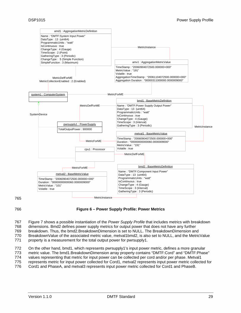
Figure 6 shows a possible instantiation of the Power Supply Profile including the power metrics. The metval1 through metval200 are values collected for interval metrics, bmd1, that represents the external input power of system1. Amd1 represents the high watermark for the bmd1 metrics, the high watermark of the system1 external input power. Psbmd1 is the interval metrics measuring the output power by pwrsupply1.
28 DMTF Standard Version 1.1.0
DSP1015 Power Supply Profile
pwrsupply1 : PowerSupply
TotalOutputPower : 900000
system1 : ComputerSystem
Name : “DMTF:System Input Power”DataType : 13 (uint64)ProgrammaticUnits : “watt”IsContinuous : trueChangeType : 4 (Gauge)TimeScope : 2 (Point)GatheringType : 3 (Periodic)ChangeType : 5 (Simple Function)SimpleFunction : 3 (Maximum)
amd1 : AggregationMetricDefinition
MetricDefForMEMetricCollectionEnabled : 2 (Enabled)
TimeStamp : “20060904072500.000000+000”MetricValue : “191”Volatile : trueAggregationTimeStamp : “20061104072500.000000+000”Aggregation Duration : “00000311000000.0000009000”
amv1 : AggregationMetricValue
MetricForME
MetricInstance
cpu1 : Processor
Name : “DMTF:Component Input Power”DataType : 13 (uint64)ProgrammaticUnits : “watt”IsContinuous : trueChangeType : 4 (Gauge)TimeScope : 3 (Interval)GatheringType : 3 (Periodic)
bmd2 : BaseMetricDefinition
TimeStamp : “20060904072500.000000+000”Duration : “00000000000060.0000009000”MetricValue : “101”Volatile : true
metval2 : BaseMetricValue
MetricDefForME
MetricInstance
MetricForME
Name : “DMTF:Power Supply Output Power”DataType : 13 (uint64)ProgrammaticUnits : “watt”IsContinuous : trueChangeType : 4 (Gauge)TimeScope : 3 (Interval)GatheringType : 3 (Periodic)
bmd1 : BaseMetricDefinition
TimeStamp : “20060904072500.000000+000”Duration : “00000000000060.0000009000”MetricValue : “191”Volatile : true
metval1 : BaseMetricValue
MetricDefForME
MetricInstance
MetricForME
SystemDevice
765
766
767 768 769 770 771
772 773 774 775 776
Figure 6 – Power Supply Profile: Power Metrics
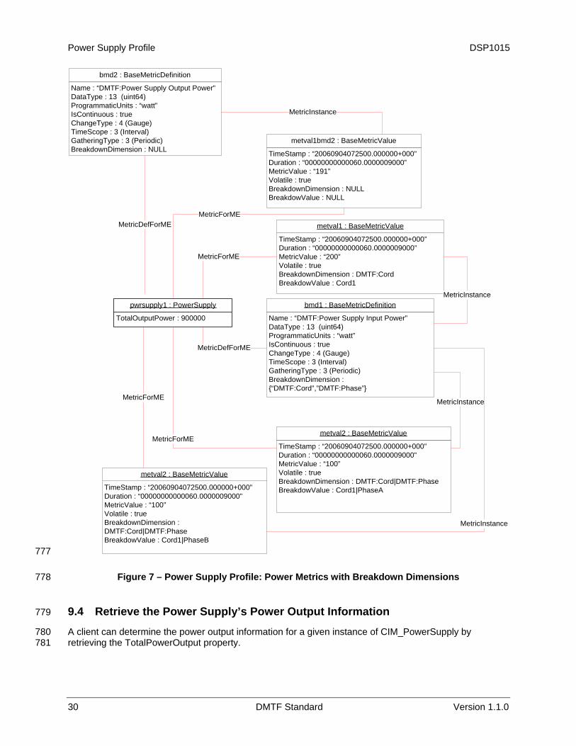
Figure 7 shows a possible instantiation of the Power Supply Profile that includes metrics with breakdown dimensions. Bmd2 defines power supply metrics for output power that does not have any further breakdown. Thus, the bmd2.BreakdownDimension is set to NULL. The BreakdownDimension and BreakdownValue of the associated metric value, metval1bmd2, is also set to NULL, and the MetricValue property is a measurement for the total output power for pwrsupply1.
On the other hand, bmd1, which represents pwrsupply1’s input power metric, defines a more granular metric value. The bmd1.BreakdownDimension array property contains “DMTF:Cord” and “DMTF:Phase” values representing that metric for input power can be collected per cord and/or per phase. Metval1 represents metric for input power collected for Cord1, metval2 represents input power metric collected for Cord1 and PhaseA, and metval3 represents input power metric collected for Cord1 and PhaseB.
Version 1.1.0 DMTF Standard 29
Power Supply Profile DSP1015
pwrsupply1 : PowerSupply
TotalOutputPower : 900000
Name : “DMTF:Power Supply Output Power”DataType : 13 (uint64)ProgrammaticUnits : “watt”IsContinuous : trueChangeType : 4 (Gauge)TimeScope : 3 (Interval)GatheringType : 3 (Periodic)BreakdownDimension : NULL
bmd2 : BaseMetricDefinition
MetricDefForME
TimeStamp : “20060904072500.000000+000”Duration : “00000000000060.0000009000”MetricValue : “191”Volatile : trueBreakdownDimension : NULLBreakdowValue : NULL
metval1bmd2 : BaseMetricValue
MetricForME
MetricInstance
TimeStamp : “20060904072500.000000+000”Duration : “00000000000060.0000009000”MetricValue : “100”Volatile : trueBreakdownDimension : DMTF:Cord|DMTF:PhaseBreakdowValue : Cord1|PhaseA
metval2 : BaseMetricValue
MetricInstance
MetricForME
Name : “DMTF:Power Supply Input Power”DataType : 13 (uint64)ProgrammaticUnits : “watt”IsContinuous : trueChangeType : 4 (Gauge)TimeScope : 3 (Interval)GatheringType : 3 (Periodic)BreakdownDimension : {“DMTF:Cord”,”DMTF:Phase”}
bmd1 : BaseMetricDefinition
TimeStamp : “20060904072500.000000+000”Duration : “00000000000060.0000009000”MetricValue : “200”Volatile : trueBreakdownDimension : DMTF:CordBreakdowValue : Cord1
metval1 : BaseMetricValue
MetricDefForME
MetricInstance
MetricForME
TimeStamp : “20060904072500.000000+000”Duration : “00000000000060.0000009000”MetricValue : “100”Volatile : trueBreakdownDimension : DMTF:Cord|DMTF:PhaseBreakdowValue : Cord1|PhaseB
metval2 : BaseMetricValue
MetricInstance
MetricForME
777
778
780 781
Figure 7 – Power Supply Profile: Power Metrics with Breakdown Dimensions
9.4 Retrieve the Power Supply’s Power Output Information 779
A client can determine the power output information for a given instance of CIM_PowerSupply by retrieving the TotalPowerOutput property.
30 DMTF Standard Version 1.1.0
DSP1015 Power Supply Profile
Version 1.1.0 DMTF Standard 31
9.5 Reset the Power Supply 782
A client can reset the power supply as follows: 783
784 785
786 787 788 789
791
792 793
794
796 797
798 799
800 801 802
803 804 805
807
808 809
810 811
813 814 815
1) For the given instance of CIM_PowerSupply, find the associated instance of CIM_EnabledLogicalElementCapabilities.
2) If the CIM_EnabledLogicalElementCapabilities.RequestedStatesSupported property is a non-empty array that contains the value 11 (Reset), execute the RequestStateChange( ) method with the value of the RequestedState parameter set to 11 (Reset), which will disable and then enable the power supply represented by this instance.
9.6 Retrieve the Power Supply Redundancy Status 790
A client can determine the redundancy status for a given instance of CIM_PowerSupply as follows:
1) Find the instance of CIM_RedundancySet that is associated with the instance of CIM_PowerSupply through an instance of CIM_MemberOfCollection.
2) Retrieve the value of the CIM_RedundancySet.RedundancyStatus property.
9.7 Find the Elements to Which the Power Supply Supplies Power 795
A client can determine the elements to which a given instance of CIM_PowerSupply supplies power as follows:
1) Find all of the CIM_SuppliesPower association instances that reference the given instance of CIM_PowerSupply.
2) If the CIM_SuppliesPower association instances exist, the CIM_SuppliesPower.Dependent properties will reference all the instances of the subclass of CIM_ManagedSystemElement that receive power from the power supply.
3) If no CIM_SuppliesPower association instances exist, select the CIM_ComputerSystem instance associated with the given instance of the CIM_PowerSupply instance through the CIM_SystemDevice association.
9.8 Determine Whether the CIM_PowerSupply.ElementName Is Modifiable 806
A client can determine whether it can modify the CIM_PowerSupply.ElementName property as follows:
1) Find the CIM_EnabledLogicalElementCapabilities instance that is associated with the CIM_PowerSupply instance.
2) Query the value of the ElementNameEditSupported property of the instance. If the value is TRUE, the client can modify the CIM_PowerSupply.ElementName property.
10 CIM Elements 812
Table 20 shows the instances of CIM Elements for this profile. Instances of the CIM Elements shall be implemented as described in Table 20. Sections 7 (“Implementation Requirements”) and section 8 (“Methods”) may impose additional requirements on these elements.

Power Supply Profile DSP1015
32 DMTF Standard Version 1.1.0
Table 20 – CIM Elements: Power Supply Profile 816
Element Name Requirement Description
Classes CIM_BaseMetricDefinition Optional See section 10.1.
CIM_BaseMetricValue Optional See section 10.2.
CIM_ElementCapabilities Conditional See section 10.3.
CIM_EnabledLogicalElementCapabilities Optional See sections 7.2 and 10.4.
CIM_HostedCollection Conditional See section 10.5.
CIM_IsSpare Optional See section 10.6.
CIM_MemberOfCollection Conditional See section 10.7.
CIM_NumericSensor Optional See sections 10.8 and 10.9.
CIM_OwningCollectionElement Conditional See section 10.16.
CIM_PowerSupply Mandatory See sections 7.1 and 10.10.
CIM_RedundancySet Optional See sections 7.7 and 10.11.
CIM_RegisteredProfile Mandatory See section 10.12.
CIM_Sensor Optional See sections 7.9 and 10.14.
CIM_SuppliesPower Optional See sections 7.6 and 10.17.
CIM_SystemDevice Mandatory See sections 7.6 and 10.15.
Indications None defined in this profile
10.1 CIM_BaseMetricDefinition 817
The CIM_BaseMetricDefinition class is defined by the Base Metrics Profile (DSP1053). The requirements denoted in
818 Table 21 are in addition to those mandated by the DSP1053. 819
820 Table 21 – Class: CIM_BaseMetricDefinition
Properties Requirement Description
Name Mandatory See section 7.10.
IsContinuous Mandatory Matches TRUE
BreakdownDimension Mandatory See section 7.10.
Table 22 describes the requirements for using CIM_BaseMetricDefinition to define a "DMTF:System Input Power Histogram" metric. These constraints are in addition to those specified in
821 DSP1053. 822
823 Table 22 – Class: CIM_BaseMetricDefinition – Histogram
Properties Requirement Notes
Name Mandatory "DMTF:System Input Power Histogram"
DataType Mandatory Matches 3 (datetime)
ProgramaticUnits Mandatory Matches NULL
ChangeType Mandatory Matches 3 (counter)
Timescope Mandatory Matches 3 (Interval) or 4 (StartupInterval)
BreakdownDimensions Mandatory Matches "DMTF:Power Range Milliwatts"
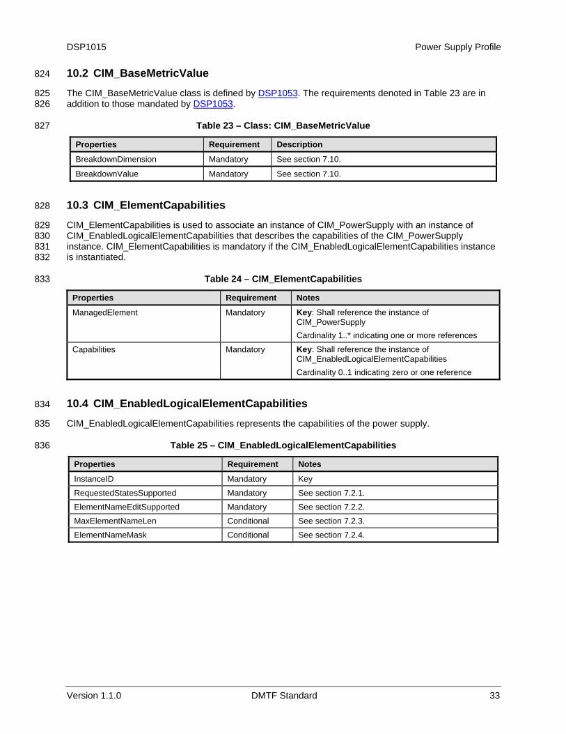
DSP1015 Power Supply Profile
Version 1.1.0 DMTF Standard 33
10.2 CIM_BaseMetricValue 824
The CIM_BaseMetricValue class is defined by DSP1053. The requirements denoted in Table 23 are in addition to those mandated by
825 DSP1053. 826
827 Table 23 – Class: CIM_BaseMetricValue
Properties Requirement Description
BreakdownDimension Mandatory See section 7.10.
BreakdownValue Mandatory See section 7.10.
10.3 CIM_ElementCapabilities 828
CIM_ElementCapabilities is used to associate an instance of CIM_PowerSupply with an instance of CIM_EnabledLogicalElementCapabilities that describes the capabilities of the CIM_PowerSupply instance. CIM_ElementCapabilities is mandatory if the CIM_EnabledLogicalElementCapabilities instance is instantiated.
829 830 831 832
833 Table 24 – CIM_ElementCapabilities
Properties Requirement Notes
ManagedElement Mandatory Key: Shall reference the instance of CIM_PowerSupply Cardinality 1..* indicating one or more references
Capabilities Mandatory Key: Shall reference the instance of CIM_EnabledLogicalElementCapabilities Cardinality 0..1 indicating zero or one reference
10.4 CIM_EnabledLogicalElementCapabilities 834
CIM_EnabledLogicalElementCapabilities represents the capabilities of the power supply. 835
836 Table 25 – CIM_EnabledLogicalElementCapabilities
Properties Requirement Notes
InstanceID Mandatory Key
RequestedStatesSupported Mandatory See section 7.2.1.
ElementNameEditSupported Mandatory See section 7.2.2.
MaxElementNameLen Conditional See section 7.2.3.
ElementNameMask Conditional See section 7.2.4.
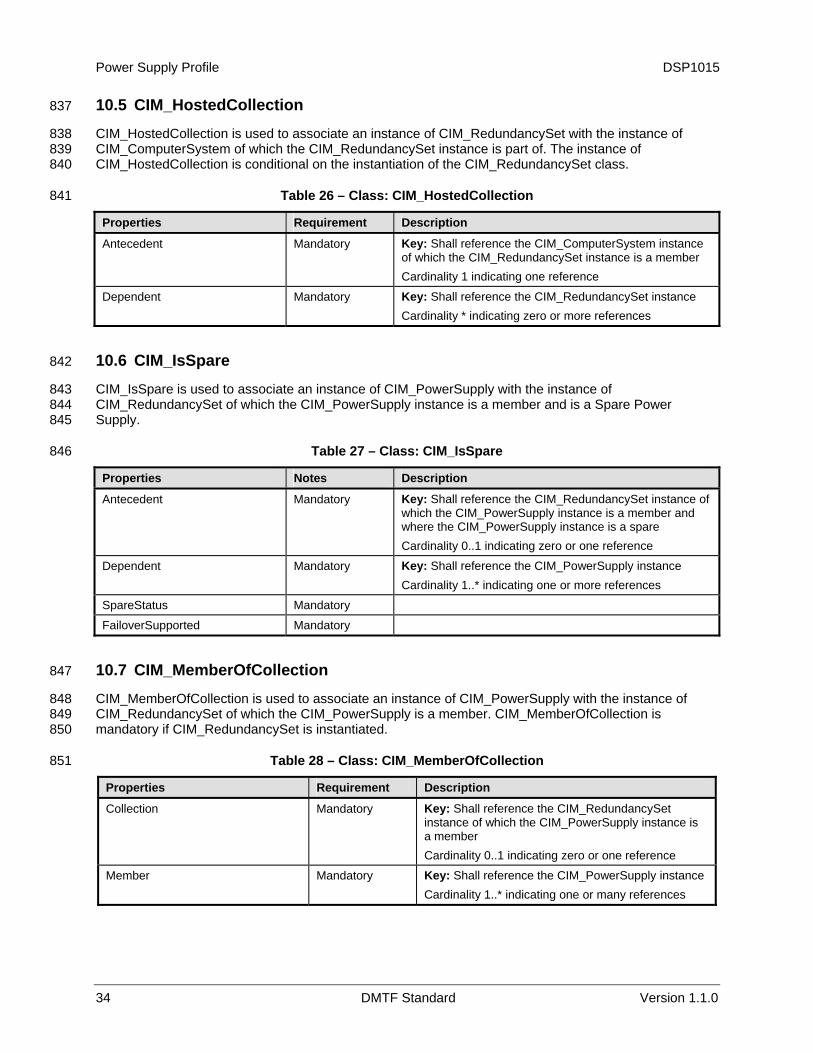
Power Supply Profile DSP1015
34 DMTF Standard Version 1.1.0
10.5 CIM_HostedCollection 837
CIM_HostedCollection is used to associate an instance of CIM_RedundancySet with the instance of CIM_ComputerSystem of which the CIM_RedundancySet instance is part of. The instance of CIM_HostedCollection is conditional on the instantiation of the CIM_RedundancySet class.
838 839 840
841 Table 26 – Class: CIM_HostedCollection
Properties Requirement Description
Antecedent Mandatory Key: Shall reference the CIM_ComputerSystem instance of which the CIM_RedundancySet instance is a member Cardinality 1 indicating one reference
Dependent Mandatory Key: Shall reference the CIM_RedundancySet instance Cardinality * indicating zero or more references
10.6 CIM_IsSpare 842
CIM_IsSpare is used to associate an instance of CIM_PowerSupply with the instance of CIM_RedundancySet of which the CIM_PowerSupply instance is a member and is a Spare Power Supply.
843 844 845
846 Table 27 – Class: CIM_IsSpare
Properties Notes Description
Antecedent Mandatory Key: Shall reference the CIM_RedundancySet instance of which the CIM_PowerSupply instance is a member and where the CIM_PowerSupply instance is a spare Cardinality 0..1 indicating zero or one reference
Dependent Mandatory Key: Shall reference the CIM_PowerSupply instance Cardinality 1..* indicating one or more references
SpareStatus Mandatory
FailoverSupported Mandatory
10.7 CIM_MemberOfCollection 847
CIM_MemberOfCollection is used to associate an instance of CIM_PowerSupply with the instance of CIM_RedundancySet of which the CIM_PowerSupply is a member. CIM_MemberOfCollection is mandatory if CIM_RedundancySet is instantiated.
848 849 850
851 Table 28 – Class: CIM_MemberOfCollection
Properties Requirement Description
Collection Mandatory Key: Shall reference the CIM_RedundancySet instance of which the CIM_PowerSupply instance is a member Cardinality 0..1 indicating zero or one reference
Member Mandatory Key: Shall reference the CIM_PowerSupply instance Cardinality 1..* indicating one or many references
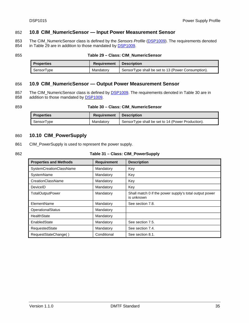
DSP1015 Power Supply Profile
Version 1.1.0 DMTF Standard 35
10.8 CIM_NumericSensor — Input Power Measurement Sensor 852
The CIM_NumericSensor class is defined by the Sensors Profile (DSP1009). The requirements denoted in
853 Table 29 are in addition to those mandated by DSP1009. 854
855 Table 29 – Class: CIM_NumericSensor
Properties Requirement Description
SensorType Mandatory SensorType shall be set to 13 (Power Consumption).
10.9 CIM_NumericSensor — Output Power Measurement Sensor 856
The CIM_NumericSensor class is defined by DSP1009. The requirements denoted in Table 30 are in addition to those mandated by
857 DSP1009. 858
859 Table 30 – Class: CIM_NumericSensor
Properties Requirement Description
SensorType Mandatory SensorType shall be set to 14 (Power Production).
10.10 CIM_PowerSupply 860
CIM_PowerSupply is used to represent the power supply. 861
862 Table 31 – Class: CIM_PowerSupply
Properties and Methods Requirement Description
SystemCreationClassName Mandatory Key
SystemName Mandatory Key
CreationClassName Mandatory Key
DeviceID Mandatory Key
TotalOutputPower Mandatory Shall match 0 if the power supply’s total output power is unknown
ElementName Mandatory See section 7.8.
OperationalStatus Mandatory
HealthState Mandatory
EnabledState Mandatory See section 7.5.
RequestedState Mandatory See section 7.4.
RequestStateChange( ) Conditional See section 8.1.
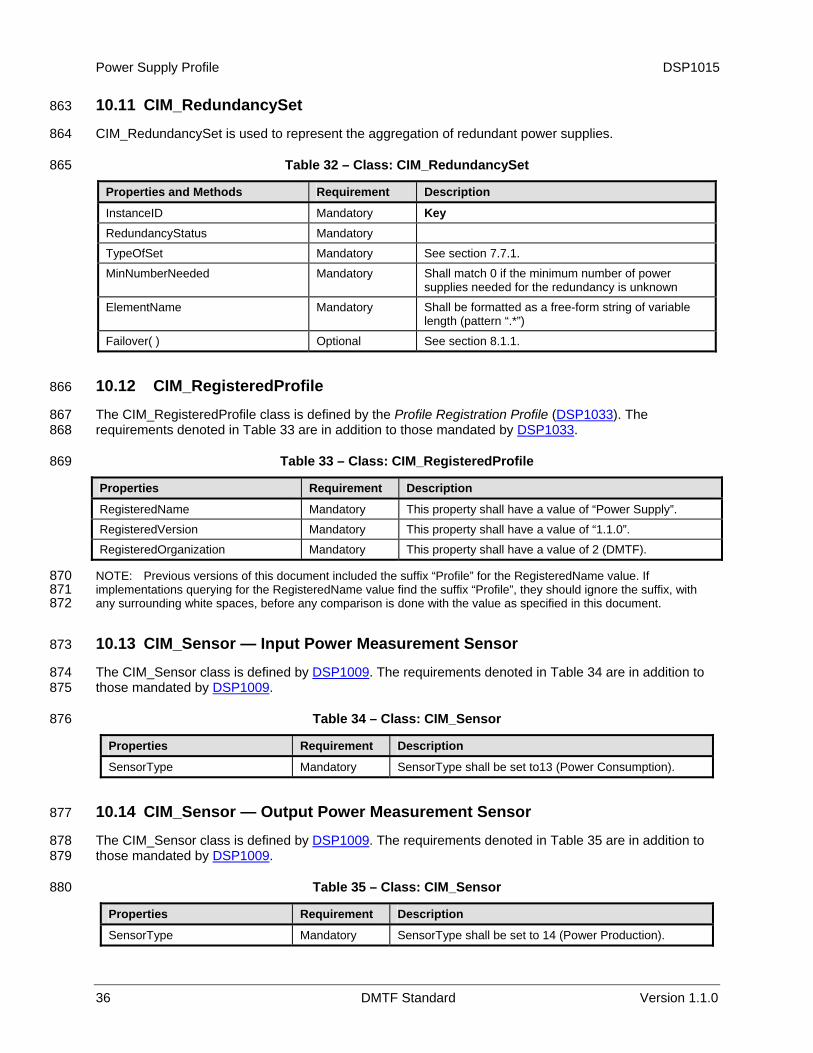
Power Supply Profile DSP1015
36 DMTF Standard Version 1.1.0
10.11 CIM_RedundancySet 863
CIM_RedundancySet is used to represent the aggregation of redundant power supplies. 864
865 Table 32 – Class: CIM_RedundancySet
Properties and Methods Requirement Description
InstanceID Mandatory Key RedundancyStatus Mandatory
TypeOfSet Mandatory See section 7.7.1.
MinNumberNeeded Mandatory Shall match 0 if the minimum number of power supplies needed for the redundancy is unknown
ElementName Mandatory Shall be formatted as a free-form string of variable length (pattern “.*”)
Failover( ) Optional See section 8.1.1.
10.12 CIM_RegisteredProfile 866
The CIM_RegisteredProfile class is defined by the Profile Registration Profile (DSP1033). The requirements denoted in
867 Table 33 are in addition to those mandated by DSP1033. 868
869 Table 33 – Class: CIM_RegisteredProfile
Properties Requirement Description
RegisteredName Mandatory This property shall have a value of “Power Supply”. RegisteredVersion Mandatory This property shall have a value of “1.1.0”.
RegisteredOrganization Mandatory This property shall have a value of 2 (DMTF).
NOTE: Previous versions of this document included the suffix “Profile” for the RegisteredName value. If implementations querying for the RegisteredName value find the suffix “Profile”, they should ignore the suffix, with any surrounding white spaces, before any comparison is done with the value as specified in this document.
870 871 872
10.13 CIM_Sensor — Input Power Measurement Sensor 873
The CIM_Sensor class is defined by DSP1009. The requirements denoted in Table 34 are in addition to those mandated by
874 DSP1009. 875
876 Table 34 – Class: CIM_Sensor
Properties Requirement Description
SensorType Mandatory SensorType shall be set to13 (Power Consumption).
10.14 CIM_Sensor — Output Power Measurement Sensor 877
The CIM_Sensor class is defined by DSP1009. The requirements denoted in Table 35 are in addition to those mandated by
878 DSP1009. 879
880 Table 35 – Class: CIM_Sensor
Properties Requirement Description
SensorType Mandatory SensorType shall be set to 14 (Power Production).
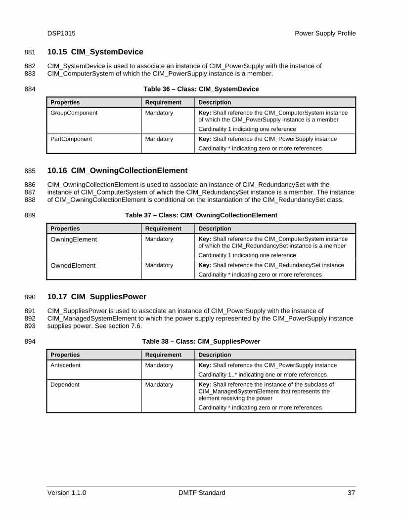
DSP1015 Power Supply Profile
Version 1.1.0 DMTF Standard 37
10.15 CIM_SystemDevice 881
CIM_SystemDevice is used to associate an instance of CIM_PowerSupply with the instance of CIM_ComputerSystem of which the CIM_PowerSupply instance is a member.
882 883
884 Table 36 – Class: CIM_SystemDevice
Properties Requirement Description
GroupComponent Mandatory Key: Shall reference the CIM_ComputerSystem instance of which the CIM_PowerSupply instance is a member Cardinality 1 indicating one reference
PartComponent Mandatory Key: Shall reference the CIM_PowerSupply instance Cardinality * indicating zero or more references
10.16 CIM_OwningCollectionElement 885
CIM_OwningCollectionElement is used to associate an instance of CIM_RedundancySet with the instance of CIM_ComputerSystem of which the CIM_RedundancySet instance is a member. The instance of CIM_OwningCollectionElement is conditional on the instantiation of the CIM_RedundancySet class.
886 887 888
889 Table 37 – Class: CIM_OwningCollectionElement
Properties Requirement Description
OwningElement Mandatory Key: Shall reference the CIM_ComputerSystem instance of which the CIM_RedundancySet instance is a member Cardinality 1 indicating one reference
OwnedElement Mandatory Key: Shall reference the CIM_RedundancySet instance Cardinality * indicating zero or more references
10.17 CIM_SuppliesPower 890
CIM_SuppliesPower is used to associate an instance of CIM_PowerSupply with the instance of CIM_ManagedSystemElement to which the power supply represented by the CIM_PowerSupply instance supplies power. See section
891 892 893
894
7.6.
Table 38 – Class: CIM_SuppliesPower
Properties Requirement Description
Antecedent Mandatory Key: Shall reference the CIM_PowerSupply instance Cardinality 1..* indicating one or more references
Dependent Mandatory Key: Shall reference the instance of the subclass of CIM_ManagedSystemElement that represents the element receiving the power Cardinality * indicating zero or more references
Power Supply Profile DSP1015
38 DMTF Standard Version 1.1.0
ANNEX A895 896 897 898
(informative)
Change Log
Version Date Description
1.0.0a 05/07/2007 Preliminary 1.0.0 version.
1.1.0a 5/22/08 Preliminary 1.1.0 version.
1.1.0 8/14/09 DMTF Standard Release
899 900