Embed Size (px)
Citation preview

J. Cent. South Univ. (2013) 20: 988−1000 DOI: 10.1007/s11771-013-1575-y
Power swing and voltage collapse identification schemes for correct distance
relay operation in power system
Ahmad F. Abidin, Azah Mohamed, Hussain Shareef
Department of Electrical, Electronic and Systems Engineering
Universiti Kebangsaan Malaysia, Bangi 43600, Malaysia
© Central South University Press and Springer-Verlag Berlin Heidelberg 2013 Abstract: The new techniques were presented for preventing undesirable distance relay maloperation during voltage collapse and power swings in transmission grids. Initially, the work focused on the development of a fast detection of voltage collapse and a three-phase fault at transmission lines by using under impedance fault detector (UIFD) and support vector machine (SVM). Likewise, an intelligent approach was developed to discriminate a fault, stable swing and unstable swing, for correct distance relay operation by using the S-transform and the probabilistic neural network (PNN). To illustrate the effectiveness of the proposed techniques, simulations were carried out on the IEEE 39-bus test system using the PSS/E and MATLAB software. Key words: under impedance fault detector; distance relay; fault; voltage collapse
Received date: 20120502; Accepted date: 20120702 Corresponding author: Azah Mohamed, Professor; Tel: +60389216103; E-mail: [email protected]
1 Introduction
Distance relay operates on the basis of impedance at the point of measurement and it is designed to initiate tripping signals of associated breakers during a fault from the measured impedance[12]. However, the relay may send trip signals during voltage instability and power swing if the measured impedance enters the tripping zone during such circumstances [34]. The cause of relay misoperation is due to the inadequate real-time diagnostic support for verifying the correctness of relay operation. For present power system, there are no real-time monitoring tools available to verify if the relay has responded to the disturbances correctly. A real-time relay monitoring tool equipped with new adaptive distance protection algorithms can prevent relay misoperation so as to mitigate the cascading blackout.
Currently, distance protection with respect to transient and voltage instabilities is one of the critical issues in transmission systems. The conventional zone 3 distance protection relays on transmission lines may not be able to distinguish between voltage instability and short circuit faults [56]. This situation can lead to the undesired operation of relays and as a consequence, the system can be exposed to voltage collapse. Thus, proper protection scheme using adaptive algorithm as an additional relay criterion needs to be deployed to provide a rigorous defence against possible voltage collapse.
Transient instability and power swings may also lead to undesirable distance relay operation. Power swings or oscillations occur following a system disturbance such as load change or fault clearance. When a power swing occurs, a change appears in the power angle which causes changes in the measurable electrical quantities at the relay location. However, the conventional power swing detectors have difficulty to detect very fast swings, distinguish faults with high grounding resistance from power swings, and clear the blocking of distance relay for symmetrical faults that occur during power swings [6]. To overcome the power swing problem, a more accurate and fast power swing blocking scheme needs to be developed for the proper operation of distance relays by using artificial intelligent (AI) techniques.
The application of AI techniques for distance relay during voltage instability and power swing is relatively new and the previous developed techniques are still not able to prevent false tripping of relays. EL-ARROUDI et al [8] presented a comprehensive distance relay settings at transmission lines based on intelligent analyses of power swing, voltage instability, load increase and load shedding has been proposed to overcome such limitation. This method is based on the expert system approach in which it gives outputs in terms of the zone reach settings, zone time delays, optimal impedance operating characteristics, fault detection settings, and minimum relay sensitivities in terms of voltage and current. To

J. Cent. South Univ. (2013) 20: 988−1000
989
validate the effectiveness of the method so as to prevent false tripping signals, experimental work needs to be done during unstable power swing and voltage collapse.
The application of wavelet transform and a self-organizing neural network to determine the accurate distance relay setting and segregate a fault against other events has been developed in order to improve the reliability and selectivity of the protection scheme [8]. This approach has the potential to be used as a scheme to prevent false tripping signals during power swing and voltage collapse. The approach is straightforward but it still has a drawback in which a relay may send unwanted tripping signal to an associated relay if a circuit breaker operates to clear a fault at the adjacent line. The unstable swing has not been considered in this technique and hence, it may not be reliable to detect such swing.
From the literature on the application of AI techniques to distance relay operation during voltage instability and power swing, further improvements are required for distance protection of transmission lines especially on dictating the correct relay operation during voltage collapse and unstable swing. In this work, two intelligent techniques have been applied to provide a fast and high reliability distance relay protection scheme. The first scheme is to prevent false relay tripping by using support vector machine which is a relatively new intelligent technique that has been applied to solve various problems encountered in power systems. The support vector machine is used to identify between a fault and a voltage collapse for distance relay operation using an under impedance fault detector which eventually enables to facilitate the correct relay action. The second distance protection scheme presents an intelligent approach for detecting unstable swings for correct distance relay operation using the S-transform and the probabilistic neural network (PNN). 2 Under impedance fault detector
Under impedance fault detector (UIFD) is mainly
utilized in distance relays produced by Siemens™ for detecting the fault at the power system. It senses the faults which are located beyond zone 3 relay boundary setting [9]. The UIFD are commonly drawn in currentvoltage (IV) plane. The X axis corresponds to the measured current, while Y axis corresponds to measured voltage. The characteristics of UIFD are based on the expressions given as
a N0.5I I (1)
b N2.5I I (2)
a r( ) 0.7V I V (3)
b r( ) 0.9V I V (4)
where IN is the nominal current and Vr is the rated bus voltage.
During normal conditions, the measured IV trajectory is located outside of the relay operating zone. Once fault occurs at one of the points covered by the relay operating zone, the IV trajectory will enter the relay tripping region. In this situation, the relay will send a trip signal to the breaker to clear the fault. Figure 1 illustrates the UIFD characteristics of distance relay and IV trajectory before and during fault. The UIFD is the fastest detector of any fault situation as it is able to sense faults which are located beyond the zone 3 relay boundary setting.
Fig. 1 UIFD characteristics of distance relay and IV trajectory
before and during fault
3 Application of intelligent techniques for
preventing distance relay operation during voltage collapse and power swing
The application of AI techniques which consists of
SMV and PNN in distance relay operation was presented. The SVM was applied for discriminating a voltage collapse and a three phase fault in the UIFD which is normally installed at transfer lines and generator buses. The S-transform which is an advanced signal processing technique and the PNN were applied for detecting stable swing, unstable swing and fault in distance relay operation. 3.1 Support vector machine
Support vector machine (SVM) is a set of supervised learning technique used for classification [10] by constructing an optimal hyperplane which separates two classes, as shown in Fig. 2.
In order to classify the data set, a maximum-margin hyper plane is required to divide the points having Yi=1 from those having Yi=1. A linear hyperplane classifier

J. Cent. South Univ. (2013) 20: 988−1000
990
Fig. 2 Optimal hyper plane separating two classes
consists of points Xi such that
T( )i if b X w X (5) where f(Xi) is the discriminant function, w is the vector perpendicular to the hyperplane, b is scalar which is used to increase the margin.
The hyperplane utilizes the following constraints to prevent the data points falling into the margin:
T( ) 1 0i iY b w X (6)
The above equations can be reformulated in the following optimization problem.
2
T
1min( )
2
s.t. ( ) 1 0i iY b
w
w X (7)
The minimization problem can be solved by using
the Lagrange multipliers as
2 T
1
1( , , ) ( ) 1
2
n
i i ii
L b Y b
w w w X (8)
For solving classification problems, SVM needs to
be solved by using a differentiating process of L(w, b, )
with respect to w and b. Thus, Eq. (8) can be expressed
as
1 , 1
1( , , )
2
n n
i i j i j i ji i j
L b Y Y
w X X (9)
For optimization purposes, Eq. (9) needs to be
maximized as
1 , 1
1max
2
n n
i i j i j i ji i j
Y Y X X
1
s.t. 0, 0n
i i ii
Y
(10)
This dual problem for i can now be solved by the standard quadratic equations. Once the dual problem is solved, the optimal weight vector w can be calculated by
1
n
i i ii
Y
w X (11)
From Eq. (11), the input vectors Xi can be defined as
support vectors, under the condition of i>0 which lies on
the margin and satisfies T( ) 1 1i iY b w X . From this
condition, the offset b can be given as
T T1( )i i i i
i
b Y b YY
w X w X (12)
Finally, the discriminant function is described by
T
T
1
( ) sgnn
i i i i ii
f Y Y
X X X w X (13)
3.2 Probabilistic neural network
The probabilistic neural network (PNN) is a radial basis network which consists of kernel-based approximation to form an estimate of the probability density functions of classes in a classification task [11]. The topological structure of PNN which comprises of four layers with one input layer, two hidden layers and one output layer is shown in Fig. 3.
Fig. 3 Topological structure of PNN
The output vector of the first hidden layer, Xwi is formed as a product of the input vector, xi and the weight vector wki, which is given by
wi i kiX x w (14) where Xwi is the output vector of first hidden layer, xi is the input vector, wki is the weight vector.

J. Cent. South Univ. (2013) 20: 988−1000
991
The product is passed through an activation function which is defined as
2wi
2
1
wi 2( 1 ) e i
X
X (15) where i=g
avg
ijD . Each summation node receives the
output from an activation function which can be formulated as
wi 21
( ) 1 , =2,3,4k
ki
R x k
X (16)
The output of PNN, yk, is determined through the
decision layer as
( ) arg(max ( )k ky x R x (17)
3.3 Classification of three phase fault and voltage
collapse using SVM for correct distance relay operation The conventional techniques used in distance relay
operation are not fast enough in distinguishing between a three-phase fault and voltage collapse and this may lead to unintended tripping of protection devices. Therefore, there is a need for fast detection of voltage collapse so as to improve the reliability of distance relay operation. To achieve faster relay response, intelligent techniques based on SVM are applied in the operation of UIFD to classify a fault and a voltage collapse for correct relay operations. The UIFD is considered because it is capable of sensing faults which are located beyond the zone 3 relay boundary setting. To demonstrate the effectiveness of the SVM, a comparison is made with the results obtained from the application of the PNN. The selection of PNN is due to the fact that it is faster and flexible in training process compared to other neural network models [12]. Figure 4 shows the proposed relay algorithm for UIFD incorporating either SVM or PNN.
Initially, the relay continuously monitors the IV trajectory at a measured bus. Once the IV trajectory enters the tripping zone setting at UIFD, the relay shall distinguish between a fault and voltage instability by using the dV/dt. The change of voltage during a fault is usually very substantial and it may produce a very large negative value of dV/dt compared to the other events except voltage collapse. The threshold value for dV/dt, (TdV/dt) is based on the following two conditions [13]:
1) d dd
,d V tV
Tt A fault or voltage collapse (18)
2) d dd
,d V tV
Tt Voltage instability (19)
For this work, the threshold value is set based on the
undervoltage triggering setting function from the
Fig. 4 Proposed relay algorithm using SVM or PNN for
detecting fault and voltage collapse
Siemens Siprotec4-7SA522 type relay. For this type of relay, the undervoltage triggering function for fault detector will be activated once the voltage is below the 5% or 0.05 p.u. of the rated voltage [14]. From this criterion, the TdV/dt is set on the basis of the formula below;
s
d 0.05
d
V
t t (20)
where ts is the sampling rate.
Since the sampling rate of the simulation is 0.01 s, the TdV/dt can be set as 5 p.u./s.
During a voltage collapse, the use of dV/dt alone is not viable to ensure the correct relay operation because the negative value of dV/dt in this situation exceeds the TdV/dt as stated in Eq. (18). Hence, SVM is deployed to classify and discriminate between a fault and a voltage collapse. If SVM classifies the event as a fault, the tripping command is triggered. The input features of SVM are selected by considering the derivative functions of bus active power, bus reactive power and bus apparent power which are given as
bus1
PX
t
(21)

J. Cent. South Univ. (2013) 20: 988−1000
992
bus
2Q
Xt
(22)
bus
3S
Xt
(23)
where Xi are input features, i{1, 2, 3}; Pbus is the active power at a selected bus; Qbus is the reactive power at a selected bus; Sbus is the apparent power at a selected bus and t is the sampling time.
The output feature of the proposed classification scheme using SVM is either “1” for three-phase fault or “1” for voltage collapse and for PNN it is defined as either “1” for three-phase fault or “2” for voltage collapse.
3.4 Classification of three-phase fault, stable and
unstable swings using the S-transform, PNN in distance relay operation To address the need for fast detection of unstable
swings so as to improve the reliability of distance relay operation, a new scheme for detecting a fault, stable swing and unstable swing at transmission lines is proposed by using the S-transform and PNN. The S-transform is used to extract features of signals obtained during a fault, stable swing and unstable swing whereas artificial neural networks based on PNN are used to classify either a fault, stable swing or unstable swing for correct distance relay operation. The selection of S-transform is due to the fact that it is able to perform multiresolution analysis on a time varying frequency which is the common feature for power swing signals. However, unlike the fast Fourier transform, the S-transform technique produces very poor frequency resolution at the high frequencies signals.
The input data comprising of bus voltage, active power and reactive power are processed to determine the derivative of bus voltage, dV/dt and the S-transform features of the voltage and active power recorded during the fault, stable swing and unstable swing conditions. The proposed relay algorithm is shown in Fig. 5. Once the apparent impedance, Za enters the tripping zone setting, the classification scheme is activated to distinguish between stable swing, unstable swing, stable swing, fault clearance and post fault conditions. During stable swing, fault clearance and post fault conditions, the relay tripping signals will not be activated in order to prevent cascading tripping situation in a power system. The classification scheme should classify an event as a fault, and a zone selection scheme is activated before the tripping command is triggered. As for the detection of an unstable swing, a fast tripping action needs to be triggered at transfer line of the associated breaker for isolation purposes.
Fig. 5 Proposed relay algorithm for detecting fault, stable
swing and unstable swing
3.4.1 S-transform theory
S-transform is a time-frequency representation known for spectral phase properties by employing a localizing Gaussian window [15]. The S-transform of a signal h(t) is defined by
2π( , ) ( , )e dftS t f g f t
(24) where g(, f) is the window function, f is the frequency
and t is the time.
The window function is a modulated Gaussian
function which can be expressed as
2
2( , ) e2π
t ff
g f (25)
Substituting Eq. (25) into Eq. (24), we get
2( ( ) )2π2( , ) ( ) e e d
2π
f tftf
S t f h t t
(26)
The S-transform can also be written as operations
on the Fourier spectrum H(f) of h(t) as
2 2
2
2π
2( , ) ( ) e e d2π
ftffS f H f t
(27)

J. Cent. South Univ. (2013) 20: 988−1000
993
The S-transform of a discrete time series is given by
letting tkT, fn/NT and assuming that 22πe and
j2πe , then Eq. (27) can be written as
2
1
0
, , 0
m mkm Nn n
m
n m nS kT H n
NT NT
(28)
where k, m, n=0, 1, ···, N1, T is the sampling interval; N is the total of sampling point.
In this work, the S-transform is used as a feature extraction tool for characterizing the features of fault, stable swing and unstable swing for distance relay operation. The extracted features are then used as inputs for the PNN. 3.4.2 Feature extraction using S-transform
The input features of the PNN are selected by considering the derivative of bus voltage,
the bus voltage
and bus active power processed by the S-transform. The formulation of the input features is described accordingly. The first feature F1 is given by
bus1 1, if 0,
VF
T
where {1, 2, 3, ···} (29)
bus
1 0, if 0V
FT
(30)
The second feature F2 is derived from the
S-transform given by
2
1500
2 bus0
500m mkN
N
m
mV
NT
2
1250
bus0
250
m mkNN
m
mV
NT
(31)
2 21, if 0F (32)
2 20, if 0F (33)
The third feature F3 which is also derived from the
S-transform is given by
2
1500
3 bus0
500m mkN
N
m
mF V
NT
(34)
where Vbus is the bus voltage.
The fourth feature F4 is given by
2
1500
4 bus0
500m mkN
N
m
mF P
NT
2
1100
bus0
100
m mkNN
m
mP
NT
(35)
where Pbus is the active power at a selected bus.
As for the output features, the developed PNN classifies fault, stable swing, unstable swing, fault clearance and post fault by representing the events as “1” for fault, “2” for stable swing, “3” for unstable swing, “4” for fault clearance and “5” for post fault. As for MPLNN, the output feature consists of [1 0 0 0 0] which denotes a fault, [0 1 0 0 0] as unstable swing, [0 0 1 0 0] as stable swing, [0 0 0 1 0] as fault clearance and [0 0 0 0 1] as post fault.
4 Results of SVM for classifying three-phase
fault and voltage collapse To improve the distance relay operation during
abnormal condition, SVM has been applied to classify three-phase fault and voltage collapse. Initially, fault and voltage collapse simulations were carried out with the IEEE 39-bus test system (Fig. 6) to generate training and testing data for the SVM and PNN. The three-phase faults with duration of 50 ms are triggered at 200% and 300% of the relay locations to generate the fault data. To simulate a voltage collapse condition, load increases from 5.5 p.u to 7.0 p.u. Figure 7 shows an example of the time domain simulations illustrating cases of fault and voltage collapse.
In Fig. 7, a sharp voltage dip between 5 s and 5.05 s is due to a three-phase fault at bus 7. This event is followed by a load increase of 7 p.u at bus 4 which starts at 10 s. As seen from Fig. 7, the voltage collapse occurs approximately at 44 s after the load increase. The IV trajectory has been monitored by using the UIFD characteristics, as shown in Fig. 8. It can be observed that the IV trajectory enters the tripping region during the three-phase fault, sudden load increase, voltage instability and voltage collapse. For a sudden load increase, the conventional relay blocks the tripping operation through load encroachment blocking method by measuring the short circuit angle [16].
As for voltage instability, the measured dV/dt is greater than its threshold, TdV/dt, and therefore does not activate the tripping function during voltage instability. However, dV/dt is not suitable for use as a discriminator for three-phase fault and voltage collapse because for both cases, the dV/dt are negative and the TdV/dt values are reached. In the proposed algorithm, dV/dt is used to fulfill the condition such that if dV/dt<TdV/dt, a fault or voltage collapse is said to occur. Once the condition is fulfilled, then only the SVM can be utilized in order to discriminate between a fault and voltage collapse.
For the SVM, 38 training data sets consisting of three-phase fault and voltage collapse events have been generated, while 105 different data sets have been used for testing purpose. Performance of the developed

J. Cent. South Univ. (2013) 20: 988−1000
994
Fig. 6 One line diagram of test system
Fig. 7 Time domain simulations illustrating cases of fault and
voltage collapse
SVM and PNN can be gauged by calculating the percentage accuracy (PACC) with respect to the actual classification output which can be defined as
correctACC 100%
NP
N (36)
where Ncorrect is the number of correct classification and N is the number of testing data.
Fig. 8 Monitored IV trajectory
4.1 Comparison of SVM and PNN results
The sample testing results of SVM with and PNN are listed in Tables 1 and 2, respectively. The numbers indicated by asterisk (“*”) in the tables denote the misclassification of testing data. The SVM produces one misclassification, as listed in Table 1. The misclassification of data has been recorded for 35 samples where SVM falsely classified three-phase fault as voltage collapse. For the PNN implementation, two

J. Cent. South Univ. (2013) 20: 988−1000
995
misclassifications have been recorded for data samples 35 and 37. For both cases, PNN has falsely classified three phase fault as voltage collapse. In terms of percentage accuracy, the SVM and PNN give accuracies of 99.05% and 98.1%, respectively. Comparing the testing results, it can be concluded that the performance of the SVM is superior to the PNN in detecting and classifying the three phase fault and voltage collapse. 4.2 Results of PNN for classifying three-phase fault,
stable and unstable swings Power swing simulations were carried out to
generate training data. A fault with duration 350 ms is triggered at different locations of the test systems in order to create different cases of stable and unstable swings. Figures 9 and 10 show examples of the time
domain simulations illustrating cases of stable and unstable swings, respectively. In the time domain simulations, a three-phase fault is created in the middle of lines 4 and 5 at 5 s. In Fig. 9, the fault clearance operation takes place at 5.1 s while in Fig. 10, the fault clearance operation take place at 5.35 s. Figure 9 shows that the oscillation of real power is damped after a few second and the oscillation is said to be a stable swing. Meanwhile, Fig. 10 shows that frequency and the magnitude of real power oscillation increase with respect to the time after a fault is cleared. This type of oscillation is known as unstable swing.
For the PNN and MLPNN implementation, 60 training data sets consisting of five particular events have been generated, while 75 different data sets have been used for testing purpose. The results obtained from
Table 1 Results of SVM
Data SVM Actual Data SVM Actual Data SVM Actual
1 1 1 36 1 1 71 1 1
2 1 1 37 1 1 72 1 1
3 1 1 38 1 1 73 1 1
4 1 1 39 1 1 74 1 1
5 1 1 40 1 1 75 1 1
6 1 1 41 1 1 76 1 1
7 1 1 42 1 1 77 1 1
8 1 1 43 1 1 78 1 1
9 1 1 44 1 1 79 1 1
10 1 1 45 1 1 80 1 1
11 1 1 46 1 1 81 1 1
12 1 1 47 1 1 82 1 1
13 1 1 48 1 1 83 1 1
14 1 1 49 1 1 84 1 1
15 1 1 50 1 1 85 1 1
16 1 1 51 1 1 86 1 1
17 1 1 52 1 1 87 1 1
18 1 1 53 1 1 88 1 1
19 1 1 54 1 1 89 1 1
20 1 1 55 1 1 90 1 1
21 1 1 56 1 1 91 1 1
22 1 1 57 1 1 92 1 1
23 1 1 58 1 1 93 1 1
24 1 1 59 1 1 94 1 1
25 1 1 60 1 1 95 1 1
26 1 1 61 1 1 96 1 1
27 1 1 62 1 1 97 1 1
28 1 1 63 1 1 98 1 1
29 1 1 64 1 1 99 1 1
30 1 1 65 1 1 100 1 1
31 1 1 66 1 1 101 1 1
32 1 1 67 1 1 102 1 1
33 1 1 68 1 1 103 1 1
34 1 1 69 1 1 104 1 1
35 1* 1* 70 1 1 105 1 1

J. Cent. South Univ. (2013) 20: 988−1000
996
Table 2 Results of PNN
Data PNN Actual Data PNN Actual Data PNN Actual
1 1 1 36 1 1 71 2 2
2 1 1 37 2* 1* 72 2 2
3 1 1 38 1 1 73 2 2
4 1 1 39 1 1 74 2 2
5 1 1 40 1 1 75 2 2
6 1 1 41 1 1 76 2 2
7 1 1 42 1 1 77 2 2
8 1 1 43 1 1 78 2 2
9 1 1 44 1 1 79 2 2
10 1 1 45 1 1 80 2 2
11 1 1 46 1 1 81 2 2
12 1 1 47 1 1 82 2 2
13 1 1 48 1 1 83 2 2
14 1 1 49 1 1 84 2 2
15 1 1 50 1 1 85 2 2
16 1 1 51 2 2 86 2 2
17 1 1 52 2 2 87 2 2
18 1 1 53 2 2 88 2 2
19 1 1 54 2 2 89 2 2
20 1 1 55 2 2 90 2 2
21 1 1 56 2 2 91 2 2
22 1 1 57 2 2 92 2 2
23 1 1 58 2 2 93 2 2
24 1 1 59 2 2 94 2 2
25 1 1 60 2 2 95 2 2
26 1 1 61 2 2 96 2 2
27 1 1 62 2 2 97 2 2
28 1 1 63 2 2 98 2 2
29 1 1 64 2 2 99 2 2
30 1 1 65 2 2 100 2 2
31 1 1 66 2 2 101 2 2
32 1 1 67 2 2 102 2 2
33 1 1 68 2 2 103 2 2
34 1 1 69 2 2 104 2 2
35 2* 1* 70 2 2 105 2 2
Fig. 9 Time domain simulation illustrating stable swing after
fault clearance
Fig. 10 Time domain simulation illustrating unstable swing
after fault clearance

J. Cent. South Univ. (2013) 20: 988−1000
997
the PNN and MLPNN for detecting and classifying stable swing, unstable swing, fault, fault clearance and post fault for distance relay operation are presented. The fault clearance and post fault have to be considered as the PNN and MLPNN outputs because the features in both situations can be misclassified as a fault or unstable swing if no specific outputs are assigned. The performance of both MLPNN and PNN in predicting the detection time of unstable swing have been evaluated by comparing it with the detection times obtained from simulations.
The architecture of the MLPNN is such that it has 4 input neurons representing the 4 input features, two hidden layers with 20 neurons and 80 neurons, respectively, and 5 output neurons representing stable swing, unstable swing, stable swing, fault clearance and post fault conditions. It uses the hyperbolic tangent transfer function and the back-propagation algorithm in
the neural network training. The mean squared error which is used as a goal for training the neural network is set at 0.000 1. The performance goal was met at 156 epochs with a training time of 10 s.
The MLPNN was tested with the 75 sets of testing data and it was found to give an overall accuracy of 93.33% with five misclassifications, in which, three misclassifications are recorded as fault clearance event while the remaining misclassifications are recorded as post fault event. The MLPNN testing results are shown as in Table 3 in which the bold number in the table denote the misclassification of events. As shown in Table 3, the MLPNN outputs are not in crisp value of 0 or 1, but rather in the range of 0 to 1. Hence, for classification purpose, a decision rule is used such that if the MLPNN output is less than 0.9 or greater than 0.1, it is considered as a misclassified output.
Table 3 MLPNN testing results
Data Actual MLPNN
SS1 0 0 1 0 0 0.008 02 0.007 68 0.986 93 0.008 55 0.011 9
SS2 0 0 1 0 0 0.001 01 0.001 00 0.998 6 0.000 03 0.001 3
SS3 0 0 1 0 0 0.000 29 0.001 44 0.992 36 0.000 03 0.005 2
SS4 0 0 1 0 0 0.000 29 0.001 44 0.992 36 0.000 03 0.005 2
SS5 0 0 1 0 0 0.001 01 0.001 00 0.998 60 0.000 03 0.001 3
SS6 0 0 1 0 0 0.000 11 0.001 06 0.998 41 0.000 68 0.001 3
SS7 0 0 1 0 0 0.000 87 0.000 93 0.998 25 0.000 11 0.001 3
SS8 0 0 1 0 0 0.000 84 0.000 95 0.998 36 0.00011 0.001 3
SS9 0 0 1 0 0 0.000 91 0.000 91 0.998 04 0.000 12 0.001 4
SS10 0 0 1 0 0 0.001 01 0.000 62 0.992 70 0.000 14 0.008 5
SS11 0 0 1 0 0 0.000 94 0.001 02 0.998 50 0.000 03 0.001 3
SS12 0 0 1 0 0 0.000 11 0.001 10 0.998 30 0.000 68 0.001 4
SS13 0 0 1 0 0 0.000 10 0.002 27 0.984 90 0.000 52 0.013 6
SS14 0 0 1 0 0 0.000 11 0.001 21 0.997 91 0.000 66 0.001 7
SS15 0 0 1 0 0 0.000 11 0.001 06 0.998 41 0.000 68 0.001 3
PF1 0 0 0 0 1 0.002 12 0.001 23 0.000 61 0.000 77 0.998 6
PF2 0 0 0 0 1 0.004 17 0.002 33 0.000 70 0.002 11 0.989 5
PF3 0 0 0 0 1 0.001 55 0.002 16 0.000 50 0.001 49 0.997 8
PF4* 0 0 0 0 1 0.994 09 0.004 287 0.090 97 0.817 18 0.001 67
PF5 0 0 0 0 1 0.000 73 0.001 77 0.000 46 0.001 08 0.999 4
PF6 0 0 0 0 1 0.000 40 0.000 01 0.001 60 0.001 43 0.994 5
PF7 0 0 0 0 1 0.001 05 0.000 53 0.000 16 0.000 83 0.999 0
PF8 0 0 0 0 1 0.001 87 0.001 47 0.000 56 0.000 66 0.997 0
PF9 0 0 0 0 1 0.002 17 0.000 34 0.000 11 0.002 50 0.996 8
PF10 0 0 0 0 1 0.001 88 0.001 67 0.000 55 0.000 44 0.997 8
PF11 0 0 0 0 1 0.000 86 0.000 29 0.001 08 0.000 69 0.998 8
PF12 0 0 0 0 1 0.000 73 0.000 17 0.000 99 0.000 77 0.998 7
PF13 0 0 0 0 1 0.000 60 0.000 07 0.000 94 0.001 13 0.998 4
PF14* 0 0 0 0 1 0.988 13 0.002 62 0.000 33 0.007 07 0.000 4 (To be continued)

J. Cent. South Univ. (2013) 20: 988−1000
998
(Continued)
Data Actual MLPNN
PF15 0 0 0 0 1 0.001 33 0.000 05 0.002 03 0.003 55 0.989 8
FC1 0 0 0 1 0 0.004 61 0.004 84 0.005 68 0.990 63 0.005 1
FC2 0 0 0 1 0 0.001 04 0.001 05 0.000 07 0.998 78 0.000 2
FC3 0 0 0 1 0 0.001 04 0.001 05 0.000 07 0.998 78 0.000 2
FC4 0 0 0 1 0 0.001 04 0.001 05 0.000 07 0.998 78 0.000 2
FC5 0 0 0 1 0 0.000 83 0.001 20 0.000 10 0.999 08 0.000 1
FC6 0 0 0 1 0 0.000 45 0.000 75 0.000 10 0.999 56 0.000 4
FC7 0 0 0 1 0 0.000 92 0.000 23 0.000 06 0.999 16 0.000 6
FC8 0 0 0 1 0 0.000 35 0.000 47 0.000 30 0.999 67 0.000 9
FC9* 0 0 0 1 0 0.030 46 0.102 89 0.232 32 0.077 34 0.350 80
FC10* 0 0 0 1 0 0.853 67 0.109 15 0.008 55 0.41258 0.253 28
FC11* 0 0 0 1 0 0.002 837 5 0.129 81 0.282 21 0.493 46 0.030 006
FC12 0 0 0 1 0 0.000 87 0.000 53 0.000 11 0.999 66 0.000 7
FC13 0 0 0 1 0 0.000 60 0.000 58 0.000 15 0.999 68 0.000 5
FC14 0 0 0 1 0 0.001 43 0.001 55 0.000 15 0.99761 0.000 5
FC15 0 0 0 1 0 0.000 67 0.000 60 0.000 13 0.999 61 0.000 3
F1 1 0 0 0 0 0.999 04 0.000 15 0.000 35 0.000 26 0.000 4
F2 1 0 0 0 0 0.999 61 0.000 14 0.000 30 0.000 29 0.001 1
F3 1 0 0 0 0 0.999 67 0.000 18 0.000 36 0.000 28 0.001 1
F4 1 0 0 0 0 0.999 51 0.000 54 0.000 50 0.000 69 0.001 2
F5 1 0 0 0 0 0.999 38 0.000 14 0.000 37 0.000 34 0.000 9
F6 1 0 0 0 0 0.999 68 0.000 15 0.000 11 0.000 44 0.000 6
F7 1 0 0 0 0 0.999 67 0.000 19 0.000 24 0.000 37 0.000 8
F8 1 0 0 0 0 0.998 67 0.000 81 0.001 04 0.000 21 0.001 1
F9 1 0 0 0 0 0.999 65 0.000 27 0.000 34 0.000 56 0.000 6
F10 1 0 0 0 0 0.998 60 0.000 87 0.000 80 0.000 52 0.001 0
F11 1 0 0 0 0 0.994 04 0.000 35 0.000 74 0.001 41 0.000 1
F12 1 0 0 0 0 0.999 38 0.000 14 0.000 29 0.000 24 0.000 5
F13 1 0 0 0 0 0.999 52 0.000 17 0.000 12 0.000 16 0.000 6
F14 1 0 0 0 0 0.999 49 0.000 27 0.000 04 0.000 06 0.001 5
F15 1 0 0 0 0 0.999 44 0.000 27 0.000 07 0.000 79 0.001 0
US1 0 1 0 0 0 0.000 32 0.998 49 0.000 83 0.000 93 0.000 7
US2 0 1 0 0 0 0.000 45 0.998 94 0.000 66 0.000 83 0.000 8
US3 0 1 0 0 0 0.000 45 0.998 94 0.000 66 0.000 83 0.000 8
US4 0 1 0 0 0 0.000 45 0.998 94 0.000 66 0.000 83 0.000 8
US5 0 1 0 0 0 0.000 45 0.998 94 0.000 66 0.000 83 0.000 8
US6 0 1 0 0 0 0.000 53 0.998 82 0.000 89 0.000 64 0.000 7
US7 0 1 0 0 0 0.000 33 0.999 02 0.000 77 0.000 81 0.000 5
US8 0 1 0 0 0 0.000 33 0.999 02 0.000 77 0.000 81 0.000 5
US9 0 1 0 0 0 0.000 31 0.993 71 0.011 42 0.000 85 8E-05
US10 0 1 0 0 0 0.000 35 0.998 70 0.000 50 0.000 92 0.001 0
US11 0 1 0 0 0 0.000 32 0.998 48 0.000 85 0.000 94 0.000 6
US12 0 1 0 0 0 0.000 50 0.998 84 0.006 64 0.000 64 0.000 3
US13 0 1 0 0 0 0.000 53 0.998 82 0.000 89 0.000 64 0.000 7
US14 0 1 0 0 0 0.000 51 0.998 84 0.006 66 0.000 64 0.000 3
US15 0 1 0 0 0 0.000 53 0.998 82 0.000 89 0.000 64 0.000 7
SS: Stable swing; US: Unstable swing; PF: Post fault; F: Fault and FC—Fault clearance; *—Misclassification
J. Cent. South Univ. (2013) 20: 988−1000
999
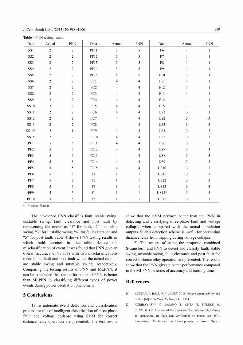
Table 4 PNN testing results
Data Actual PNN Data Actual PNN Data Actual PNN
SS1 2 2 PF11 5 5 F6 1 1
SS2 2 2 PF12 5 5 F7 1 1
SS3 2 2 PF13 5 5 F8 1 1
SS4 2 2 PF14 5 5 F9 1 1
SS5 2 2 PF15 5 5 F10 1 1
SS6 2 2 FC1 4 4 F11 1 1
SS7 2 2 FC2 4 4 F12 1 1
SS8 2 2 FC3 4 4 F13 1 1
SS9 2 2 FC4 4 4 F14 1 1
SS10 2 2 FC5 4 4 F15 1 1
SS11 2 2 FC6 4 4 US1 3 3
SS12 2 2 FC7 4 4 US2 3 3
SS13 2 2 FC8 4 4 US3 3 3
SS14* 2 1 FC9 4 4 US4 3 3
SS15 2 2 FC10 4 4 US5 3 3
PF1 5 5 FC11 4 4 US6 3 3
PF2 5 5 FC12 4 4 US7 3 3
PF3 5 5 FC13 4 4 US8 3 3
PF4 5 5 FC14 4 4 US9 3 3
PF5 5 5 FC15 4 4 US10 3 3
PF6 5 5 F1 1 1 US11 3 3
PF7 5 5 F2 1 1 US12 3 3
PF8 5 5 F3 1 1 US13 3 3
PF9 5 5 F4 1 1 US14* 3 5
PF10 5 5 F5 1 1 US15 3 3
*—Misclassification The developed PNN classifies fault, stable swing,
unstable swing, fault clearance and post fault by representing the events as “1” for fault, “2” for stable swing, “3” for unstable swing, “4” for fault clearance and “5” for post fault. Table 4 shows PNN testing results in which bold number in the table denote the misclassification of event. It was found that PNN give an overall accuracy of 97.33% with two misclassifications recorded as fault and post fault where the actual outputs are stable swing and unstable swing, respectively. Comparing the testing results of PNN and MLPNN, it can be concluded that the performance of PNN is better than MLPPN in classifying different types of power events during power oscillation phenomena. 5 Conclusions
1) To automate event detection and classification process, results of intelligent classification of three-phase fault and voltage collapse using SVM for correct distance relay operation are presented. The test results
show that the SVM perform better than the PNN in detecting and classifying three-phase fault and voltage collapse when compared with the actual simulation outputs. Such a detection scheme is useful for preventing distance relay from tripping during voltage collapse.
2) The results of using the proposed combined S-transform and PNN to detect and classify fault, stable swing, unstable swing, fault clearance and post fault for correct distance relay operation are presented. The results show that the PNN gives a better performance compared to the MLPNN in terms of accuracy and training time.
References [1] KUNDUR P, BALU N J, LAUBY M G. Power system stability and
control [M]. New York. McGraw-Hill, 1994
[2] KURIBAYASHI H, SASANO T, OHTA T, FURUSE M,
FUJIMOTO T. Analysis of the operation of a distance relay during
an unbalanced arc fault and verification by model tests [C]//
International Conference on Developments in Power System

J. Cent. South Univ. (2013) 20: 988−1000
1000
Protection, Amsterdam: IEEE Press, 2001: 7881.
[3] MECHRAOUI A, THOMAS D W P. A new blocking principle with
phase and earth fault detection during fast power swings for distance
protection [J]. IEEE Transactions on Power Deliver, 1995, 10(3):
12421248.
[4] JONSSON M, DAALDER J. Distance protection and voltage
stability [C]// International Conference on Power System Technology,
2000: 971976.
[5] JIN M, SIDHU T S. Adaptive load encroachment prevention scheme
for distance protection [J]. Electric Power Systems Research, 2008,
78(10): 16931700.
[6] AHMAD F B A, AZAH M. On the use of voltage stability index to
prevent undesirable distance relay operation during voltage
instability [C]// International Conference on Environment and
Electrical Engineering (EEEIC), Prague: IEEE Press, 2010: 384387
[7] ZADEH H K, LI Z. A novel power swing blocking scheme using
adaptive neuro-fuzzy inference system [J]. Electric Power Systems
Research, 2008, 78(7): 11381146.
[8] EL-ARROUDI K, JOÓS G, MCGILLIS D, BREARLEY R.
Comprehensive transmission distance protection settings using an
intelligent-based analysis of events and consequences [J]. IEEE
Transactions on Power Delivery, 2005, 20(3): 18171824.
[9] ZHANG N, KEZUNOVIC M. Transmission line boundary
protection using wavelet transform and neural network [J]. IEEE
Transaction on Power Delivery, 2007, 22(2): 859869. [10] ZIEGLER G. Numerical distance protection: Principles and
applications [M]. Wiley-VCH, 2011.
[11] BURGES C J C. Advances in kernel methods: Support vector
learning [M]. The MIT Press, 1999.
[12] ZAKNICH A. Neural networks for intelligent signal processing [M].
World Scientific Pub Co Inc, 2003.
[13] EL EMARY I M M, RAMAKRISHNAN S. On the application of
various probabilistic neural networks in solving different pattern
classification problems [J]. World Applied Sciences Journal, 2008,
4(6): 772780.
[14] JONSSON M, DAALDER J E. An adaptive scheme to prevent
undesirable distance protection operation during voltage instability
[J]. IEEE Transactions on Power Delivery, 2003, 18(4): 11741180.
[15] S. 7SA522. Distance Protection Relay for Transmission Lines
[EB/OL]. [20090612]: http://www.energy.siemens.com
[16] STOCKWELL R G, MANSINHA L, LOWE R P. Localization of the
complex spectrum: The S transform [J]. IEEE Transactions on Signal
Processing, 1996, 44(4): 9981001.
(Edited by DENG Lü-xiang)