Embed Size (px)
Citation preview
POWER SYSTEM ANALYSIS
KINGS COLLEGE OF ENGINEERING
Punalkulam – 613 303
DEPARTMENT OF ELECTRICAL AND ELECTRONICS ENGINEERING
POWER SYSTEM ANALYSIS
QUESTION BANK
UNIT – I THE POWER SYSTEM – AN OVERVIEW AND MODELLING
PART – A
(TWO MARK QUESTIONS)
1. What is a single line diagram? 2. A generator rated at 30 MVA, 11 kV has a reactance of 20%. Calculate it’s per unit
reactance for a base of 50 MVA and 10 kV 3. Define per unit value. 4. Draw equivalent π circuit of a transformer. 5. Write the equation for per unit impedance. 6. Represent a short transmission line of 3 phase into its equivalent single phase circuit. 7. Write any two advantages of per-unit representation. 8. What is the need for system analysis in planning and operation of power system? 9. How is generator in transient analysis represented? 10. What are the advantages of per unit system? 11. List the different components of power system. 12. What is a bus? 13. What are the approximations made in reactance diagram? 14. How are the base values chosen in per unit representation of a power system? 15. Write the equation converting the p.u. impedance expressed in one base to another base. 16. What is bus impedance matrix? 17. Define primitive matrix.
PART – B
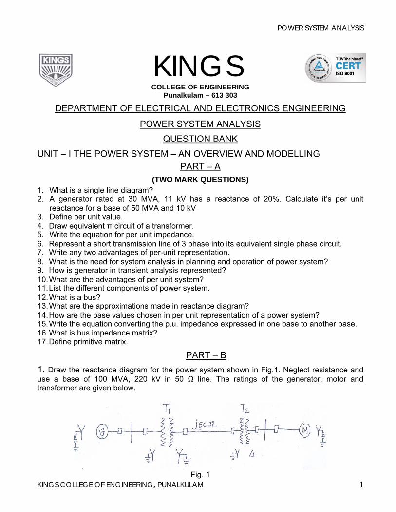
1. Draw the reactance diagram for the power system shown in Fig.1. Neglect resistance and use a base of 100 MVA, 220 kV in 50 Ω line. The ratings of the generator, motor and transformer are given below.
KINGS COLLEGE OF ENGINEERING, PUNALKULAM 1Fig. 1
POWER SYSTEM ANALYSIS
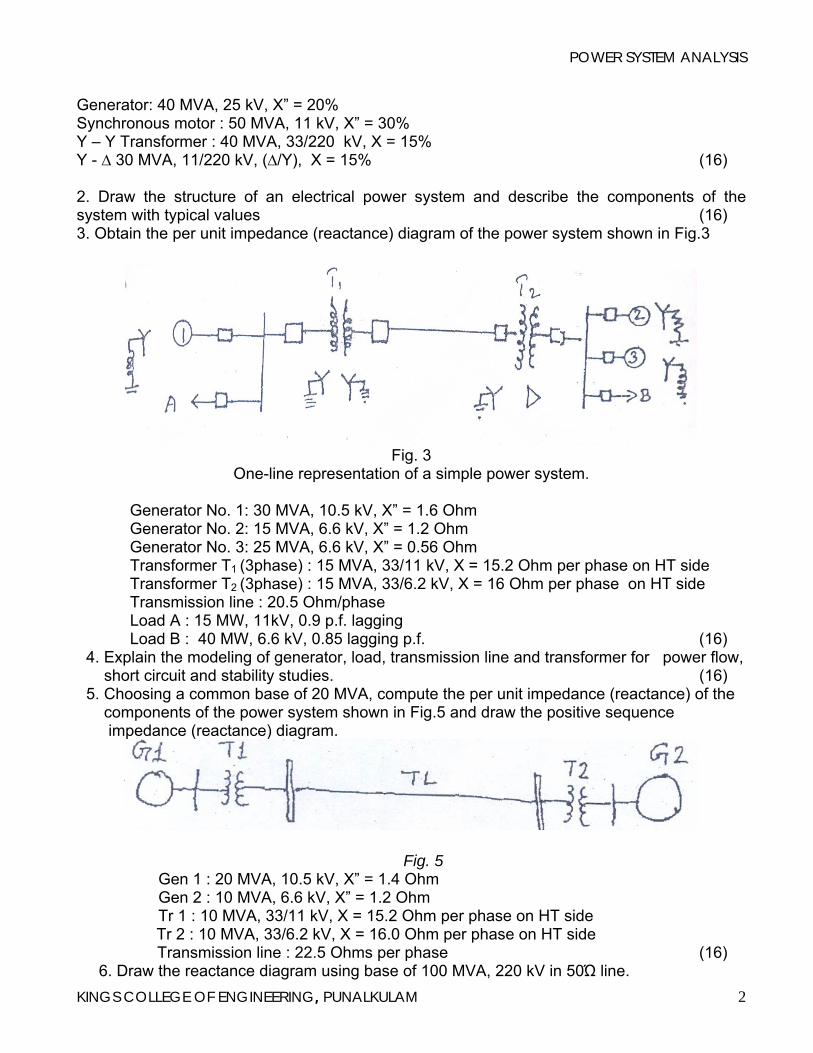
Generator: 40 MVA, 25 kV, X” = 20% Synchronous motor : 50 MVA, 11 kV, X” = 30% Y – Y Transformer : 40 MVA, 33/220 kV, X = 15% Y - ∆ 30 MVA, 11/220 kV, (∆/Y), X = 15% (16) 2. Draw the structure of an electrical power system and describe the components of the system with typical values (16) 3. Obtain the per unit impedance (reactance) diagram of the power system shown in Fig.3
Fig. 3
One-line representation of a simple power system.
Generator No. 1: 30 MVA, 10.5 kV, X” = 1.6 Ohm Generator No. 2: 15 MVA, 6.6 kV, X” = 1.2 Ohm Generator No. 3: 25 MVA, 6.6 kV, X” = 0.56 Ohm Transformer T1 (3phase) : 15 MVA, 33/11 kV, X = 15.2 Ohm per phase on HT side Transformer T2 (3phase) : 15 MVA, 33/6.2 kV, X = 16 Ohm per phase on HT side Transmission line : 20.5 Ohm/phase Load A : 15 MW, 11kV, 0.9 p.f. lagging Load B : 40 MW, 6.6 kV, 0.85 lagging p.f. (16)
4. Explain the modeling of generator, load, transmission line and transformer for power flow, short circuit and stability studies. (16) 5. Choosing a common base of 20 MVA, compute the per unit impedance (reactance) of the components of the power system shown in Fig.5 and draw the positive sequence impedance (reactance) diagram.
Fig. 5 Gen 1 : 20 MVA, 10.5 kV, X” = 1.4 Ohm Gen 2 : 10 MVA, 6.6 kV, X” = 1.2 Ohm Tr 1 : 10 MVA, 33/11 kV, X = 15.2 Ohm per phase on HT side
Tr 2 : 10 MVA, 33/6.2 kV, X = 16.0 Ohm per phase on HT side Transmission line : 22.5 Ohms per phase (16)
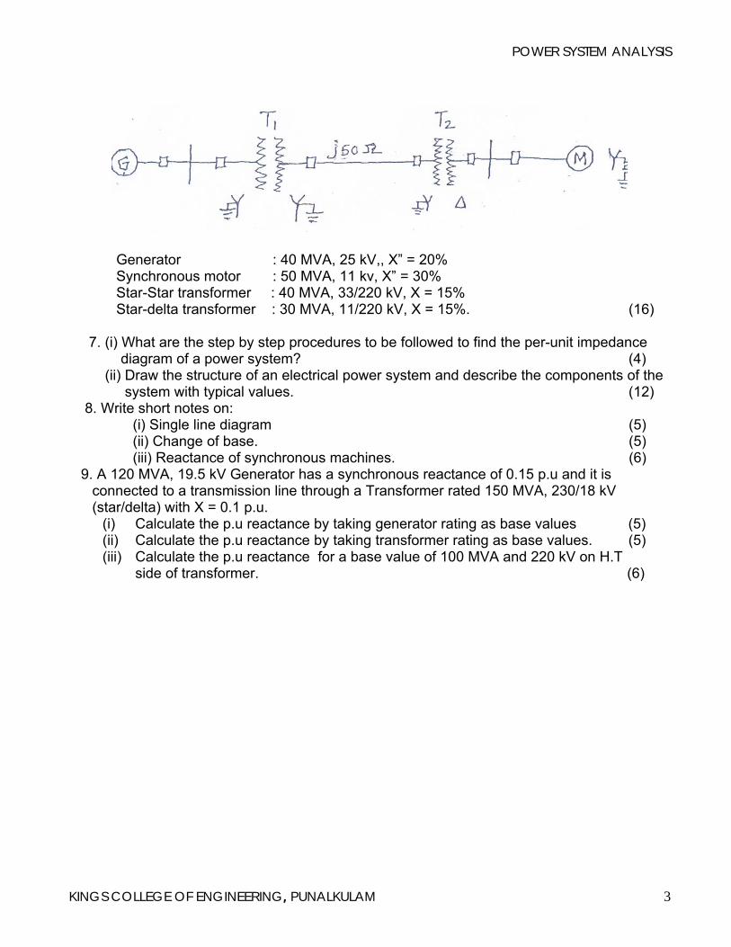
6. Draw the reactance diagram using base of 100 MVA, 220 kV in 50Ώ line.
KINGS COLLEGE OF ENGINEERING, PUNALKULAM 2
POWER SYSTEM ANALYSIS
Generator : 40 MVA, 25 kV,, X” = 20% Synchronous motor : 50 MVA, 11 kv, X” = 30% Star-Star transformer : 40 MVA, 33/220 kV, X = 15% Star-delta transformer : 30 MVA, 11/220 kV, X = 15%. (16)
7. (i) What are the step by step procedures to be followed to find the per-unit impedance diagram of a power system? (4) (ii) Draw the structure of an electrical power system and describe the components of the system with typical values. (12) 8. Write short notes on: (i) Single line diagram (5) (ii) Change of base. (5) (iii) Reactance of synchronous machines. (6) 9. A 120 MVA, 19.5 kV Generator has a synchronous reactance of 0.15 p.u and it is
connected to a transmission line through a Transformer rated 150 MVA, 230/18 kV (star/delta) with X = 0.1 p.u.
(i) Calculate the p.u reactance by taking generator rating as base values (5) (ii) Calculate the p.u reactance by taking transformer rating as base values. (5) (iii) Calculate the p.u reactance for a base value of 100 MVA and 220 kV on H.T
side of transformer. (6)
KINGS COLLEGE OF ENGINEERING, PUNALKULAM 3
POWER SYSTEM ANALYSIS
UNIT – II - POWER FLOW ANALYSIS PART- A
1. What is the information that is obtained from load flow study? 2. Write the need for slack bus/swing bus. 3. What are the three classes of buses of a power system used in power flow analysis? What
are the quantities to be specified and to be computed for each class during power flow solution?
4. What is a slack bus? 5. What is meant by acceleration factor in Gauss-Seidel load flow solution and its best value? 6. What is P-Q bus in power flow analysis? 7. What do you mean by flat voltage start? 8. What do you mean by an Infinite bus? 9. What are the constraints to be satisfied to solve load flow equation for a given bus load
configuration? 10. What technique is used to solve load flow problems using Zbus (Bus impedance matrix)? 11. Define load bus. 12. What are the disadvantages in reactive power compensation by shunt capacitors and how
it can be overcome? 13. What is off-nominal transformer ratio? 14. What is regulating Transformer and boosting Transformer? 15. How a load flow study is performed? 16. Compare Gauss-Seidel method, Newton-Raphson method and FDPF method with respect to number of iteration taken for convergence and memory requirements.
PART – B
1. Derive load flow algorithm using Gauss – Seidel method with flow chart and discuss the advantages of the method. (16)
2. Derive load flow algorithm using Newton-Raphson method with flow chart and state the importance of the method. (16) 3. Explain clearly the algorithmic steps for solving load flow equation using Newton – Raphson
method (polar form) when the system contains all types of buses. Assume that the generators at the P-V buses have adequate Q Limits. (16)
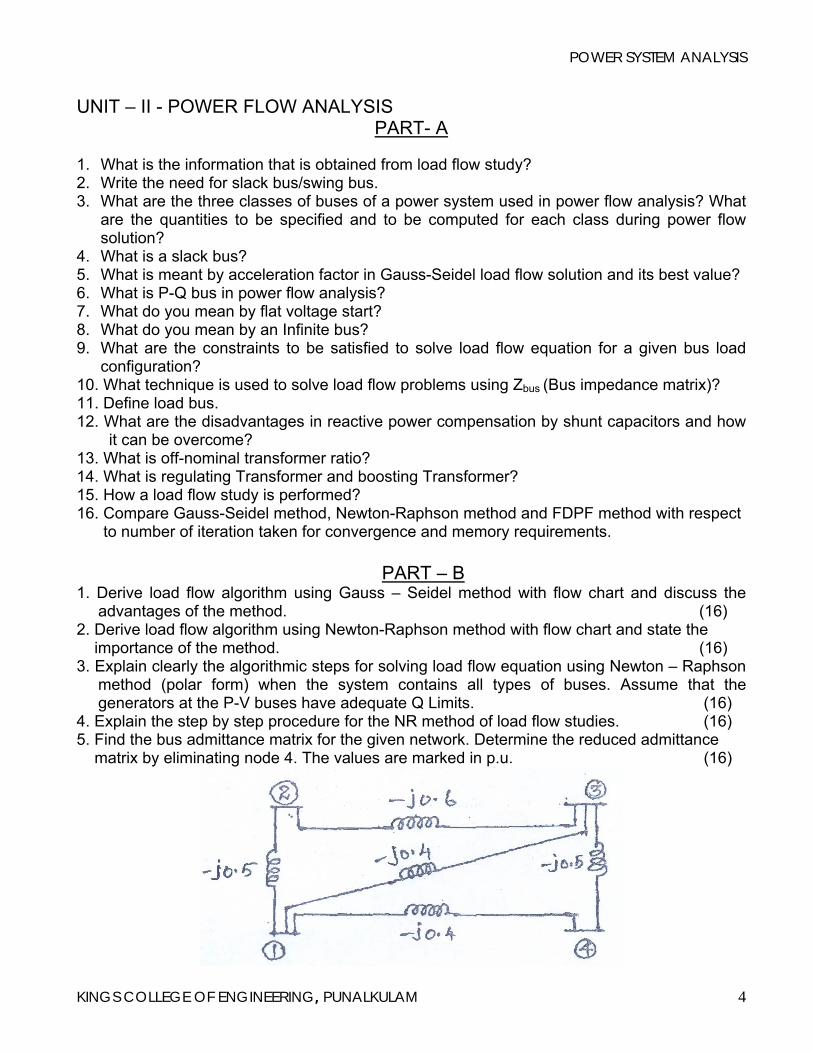
4. Explain the step by step procedure for the NR method of load flow studies. (16) 5. Find the bus admittance matrix for the given network. Determine the reduced admittance matrix by eliminating node 4. The values are marked in p.u. (16)
KINGS COLLEGE OF ENGINEERING, PUNALKULAM 4
POWER SYSTEM ANALYSIS
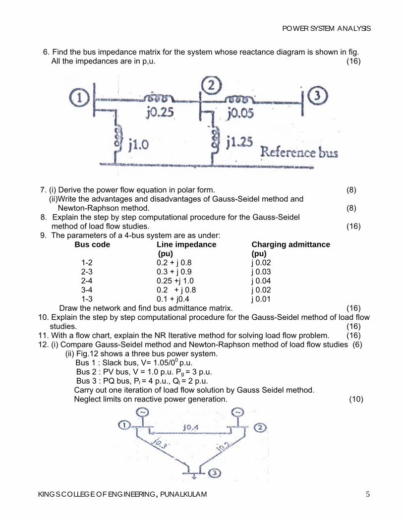
6. Find the bus impedance matrix for the system whose reactance diagram is shown in fig. All the impedances are in p,u. (16)
7. (i) Derive the power flow equation in polar form. (8) (ii)Write the advantages and disadvantages of Gauss-Seidel method and Newton-Raphson method. (8) 8. Explain the step by step computational procedure for the Gauss-Seidel method of load flow studies. (16)
9. The parameters of a 4-bus system are as under: Bus code Line impedance Charging admittance (pu) (pu) 1-2 0.2 + j 0.8 j 0.02 2-3 0.3 + j 0.9 j 0.03 2-4 0.25 +j 1.0 j 0.04 3-4 0.2 + j 0.8 j 0.02 1-3 0.1 + j0.4 j 0.01 Draw the network and find bus admittance matrix. (16)
10. Explain the step by step computational procedure for the Gauss-Seidel method of load flow studies. (16)
11. With a flow chart, explain the NR Iterative method for solving load flow problem. (16) 12. (i) Compare Gauss-Seidel method and Newton-Raphson method of load flow studies (6)
(ii) Fig.12 shows a three bus power system. Bus 1 : Slack bus, V= 1.05/00 p.u. Bus 2 : PV bus, V = 1.0 p.u. Pg = 3 p.u. Bus 3 : PQ bus, Pl = 4 p.u., Ql = 2 p.u. Carry out one iteration of load flow solution by Gauss Seidel method. Neglect limits on reactive power generation. (10)
KINGS COLLEGE OF ENGINEERING, PUNALKULAM 5
POWER SYSTEM ANALYSIS
UNIT – III - SYMMETRICAL FAULT ANALYSIS
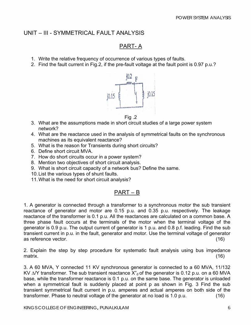
PART- A 1. Write the relative frequency of occurrence of various types of faults. 2. Find the fault current in Fig.2, if the pre-fault voltage at the fault point is 0.97 p.u.?
Fig .2
3. What are the assumptions made in short circuit studies of a large power system network?
4. What are the reactance used in the analysis of symmetrical faults on the synchronous machines as its equivalent reactance?
5. What is the reason for Transients during short circuits? 6. Define short circuit MVA. 7. How do short circuits occur in a power system? 8. Mention two objectives of short circuit analysis. 9. What is short circuit capacity of a network bus? Define the same. 10. List the various types of shunt faults. 11. What is the need for short circuit analysis?
PART – B
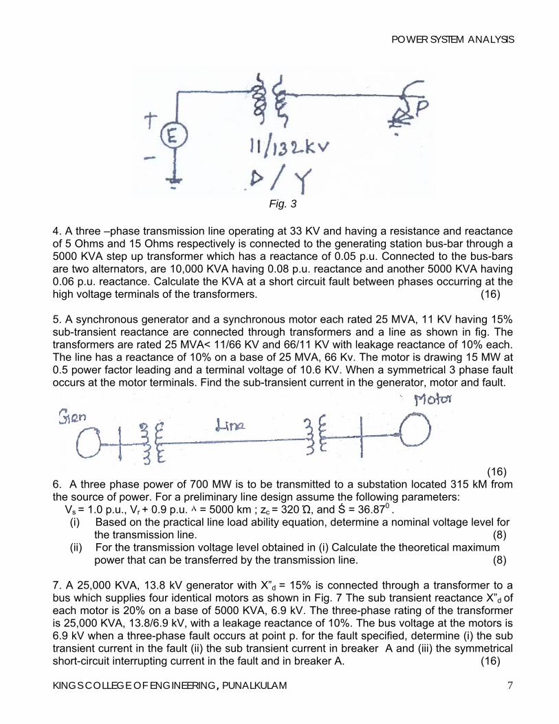
1. A generator is connected through a transformer to a synchronous motor the sub transient reactance of generator and motor are 0.15 p.u. and 0.35 p.u. respectively. The leakage reactance of the transformer is 0.1 p.u. All the reactances are calculated on a common base. A three phase fault occurs at the terminals of the motor when the terminal voltage of the generator is 0.9 p.u. The output current of generator is 1 p.u. and 0.8 p.f. leading. Find the sub transient current in p.u. in the fault, generator and motor. Use the terminal voltage of generator as reference vector. (16) 2. Explain the step by step procedure for systematic fault analysis using bus impedance matrix. (16) 3. A 60 MVA, Y connected 11 KV synchronous generator is connected to a 60 MVA, 11/132 KV ∆/Y transformer. The sub transient reactance X”d of the generator is 0.12 p.u. on a 60 MVA base, while the transformer reactance is 0.1 p.u. on the same base. The generator is unloaded when a symmetrical fault is suddenly placed at point p as shown in Fig. 3 Find the sub transient symmetrical fault current in p.u. amperes and actual amperes on both side of the transformer. Phase to neutral voltage of the generator at no load is 1.0 p.u. (16)
KINGS COLLEGE OF ENGINEERING, PUNALKULAM 6
POWER SYSTEM ANALYSIS
Fig. 3
4. A three –phase transmission line operating at 33 KV and having a resistance and reactance of 5 Ohms and 15 Ohms respectively is connected to the generating station bus-bar through a 5000 KVA step up transformer which has a reactance of 0.05 p.u. Connected to the bus-bars are two alternators, are 10,000 KVA having 0.08 p.u. reactance and another 5000 KVA having 0.06 p.u. reactance. Calculate the KVA at a short circuit fault between phases occurring at the high voltage terminals of the transformers. (16) 5. A synchronous generator and a synchronous motor each rated 25 MVA, 11 KV having 15% sub-transient reactance are connected through transformers and a line as shown in fig. The transformers are rated 25 MVA< 11/66 KV and 66/11 KV with leakage reactance of 10% each. The line has a reactance of 10% on a base of 25 MVA, 66 Kv. The motor is drawing 15 MW at 0.5 power factor leading and a terminal voltage of 10.6 KV. When a symmetrical 3 phase fault occurs at the motor terminals. Find the sub-transient current in the generator, motor and fault.
(16) 6. A three phase power of 700 MW is to be transmitted to a substation located 315 kM from the source of power. For a preliminary line design assume the following parameters: Vs = 1.0 p.u., Vr + 0.9 p.u. ٨ = 5000 km ; zc = 320 Ώ, and Ś = 36.870 .
(i) Based on the practical line load ability equation, determine a nominal voltage level for the transmission line. (8) (ii) For the transmission voltage level obtained in (i) Calculate the theoretical maximum power that can be transferred by the transmission line. (8)
7. A 25,000 KVA, 13.8 kV generator with X”d = 15% is connected through a transformer to a bus which supplies four identical motors as shown in Fig. 7 The sub transient reactance X”d of each motor is 20% on a base of 5000 KVA, 6.9 kV. The three-phase rating of the transformer is 25,000 KVA, 13.8/6.9 kV, with a leakage reactance of 10%. The bus voltage at the motors is 6.9 kV when a three-phase fault occurs at point p. for the fault specified, determine (i) the sub transient current in the fault (ii) the sub transient current in breaker A and (iii) the symmetrical short-circuit interrupting current in the fault and in breaker A. (16)
KINGS COLLEGE OF ENGINEERING, PUNALKULAM 7
POWER SYSTEM ANALYSIS
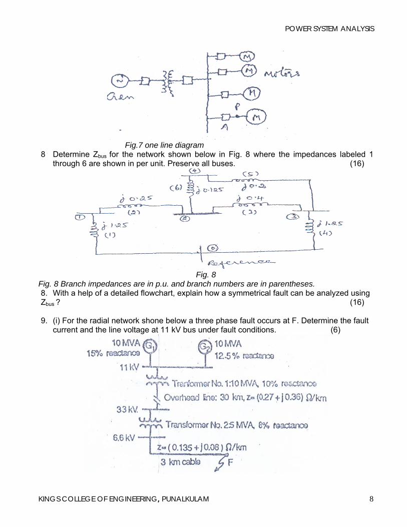
Fig.7 one line diagram 8 Determine Zbus for the network shown below in Fig. 8 where the impedances labeled 1
through 6 are shown in per unit. Preserve all buses. (16)
Fig. 8
Fig. 8 Branch impedances are in p.u. and branch numbers are in parentheses. 8. With a help of a detailed flowchart, explain how a symmetrical fault can be analyzed using Zbus ? (16)
9. (i) For the radial network shone below a three phase fault occurs at F. Determine the fault
current and the line voltage at 11 kV bus under fault conditions. (6)
KINGS COLLEGE OF ENGINEERING, PUNALKULAM 8
POWER SYSTEM ANALYSIS
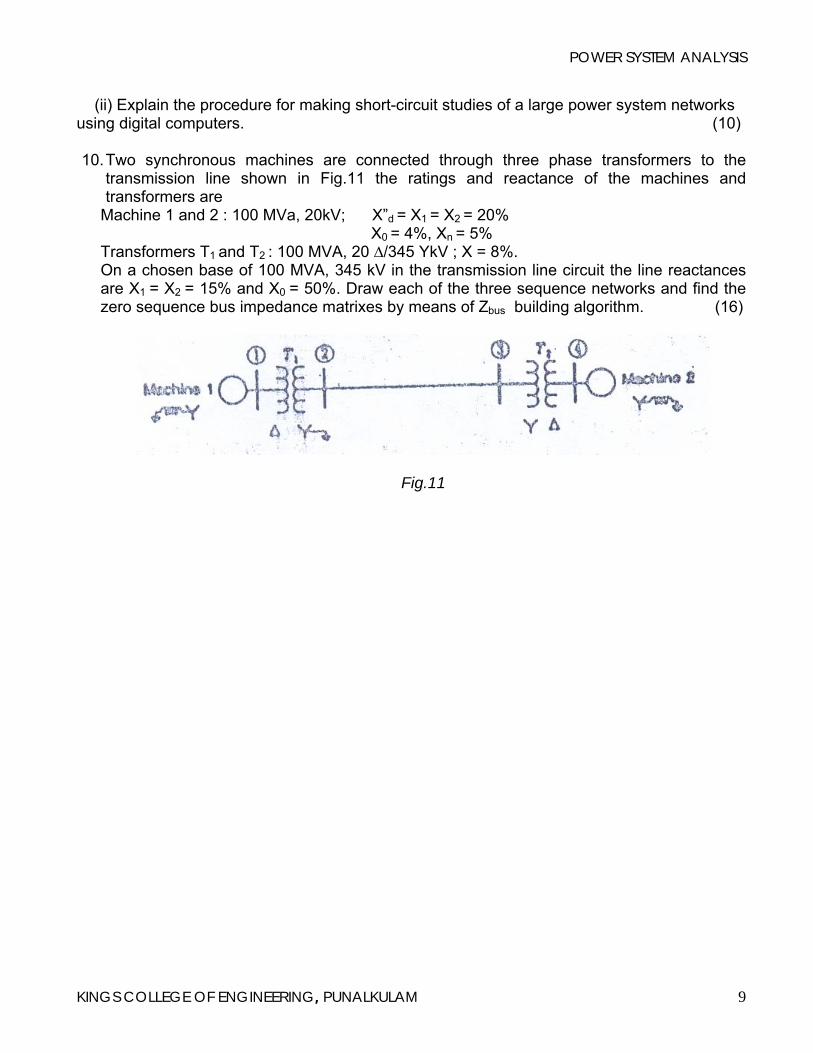
(ii) Explain the procedure for making short-circuit studies of a large power system networks using digital computers. (10) 10. Two synchronous machines are connected through three phase transformers to the
transmission line shown in Fig.11 the ratings and reactance of the machines and transformers are
Machine 1 and 2 : 100 MVa, 20kV; X”d = X1 = X2 = 20% X0 = 4%, Xn = 5% Transformers T1 and T2 : 100 MVA, 20 ∆/345 YkV ; X = 8%. On a chosen base of 100 MVA, 345 kV in the transmission line circuit the line reactances are X1 = X2 = 15% and X0 = 50%. Draw each of the three sequence networks and find the zero sequence bus impedance matrixes by means of Zbus building algorithm. (16)
Fig.11
KINGS COLLEGE OF ENGINEERING, PUNALKULAM 9
POWER SYSTEM ANALYSIS
UNIT – IV - SYMMETRICAL COMPONENTS AND UNBALANCED FAULT ANALYSIS
PART- A
1. Draw the equivalent sequence network diagram for a single phase to ground fault in a
power system. 2. Draw the zero sequence equivalent network diagram for a 3 phase star connected
alternator with reactance earthing. 3. Write the symmetrical components of three phase system. 4. Draw the equivalent sequence network for a Line-Line bolted fault in a power system. 5. What is a sequence network? 6. What are unsymmetrical faults? 7. Draw the zero sequence network of a star-connected alternator with zero sequence
impedance zgo when the neutral is grounded through an impedance zn . 8. Draw the equivalent sequence network diagram for a single phase to ground fault in a
power system. 9. Compute the following in polar form
0120 1a
i. ja ii. 21 aa
10. Draw the zero sequence diagram of a synchronous generator with neutral grounded 11. Draw the negative sequence diagram of a synchronous machine
PART- B
1. Derive the expression for fault current in Line-to-Line fault on an unloaded generator in terms of symmetrical components. (16)
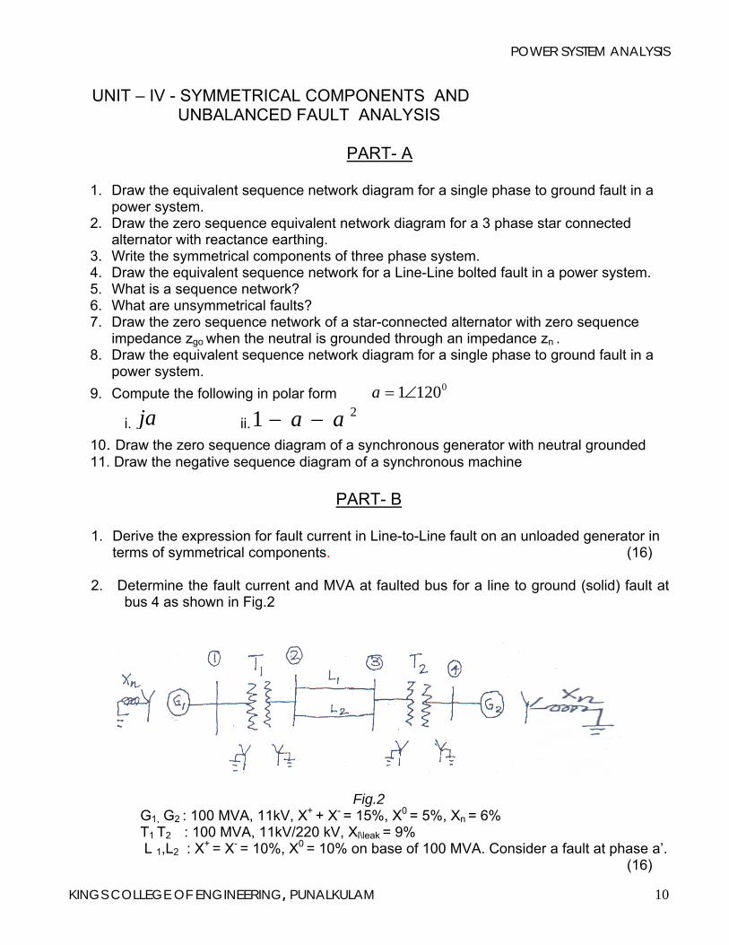
2. Determine the fault current and MVA at faulted bus for a line to ground (solid) fault at
bus 4 as shown in Fig.2
Fig.2 G1, G2 : 100 MVA, 11kV, X+ + X- = 15%, X0 = 5%, Xn = 6% T1 T2 : 100 MVA, 11kV/220 kV, Xl\leak = 9% L 1,L2 : X
+ = X- = 10%, X0 = 10% on base of 100 MVA. Consider a fault at phase a’. (16)
KINGS COLLEGE OF ENGINEERING, PUNALKULAM 10
POWER SYSTEM ANALYSIS
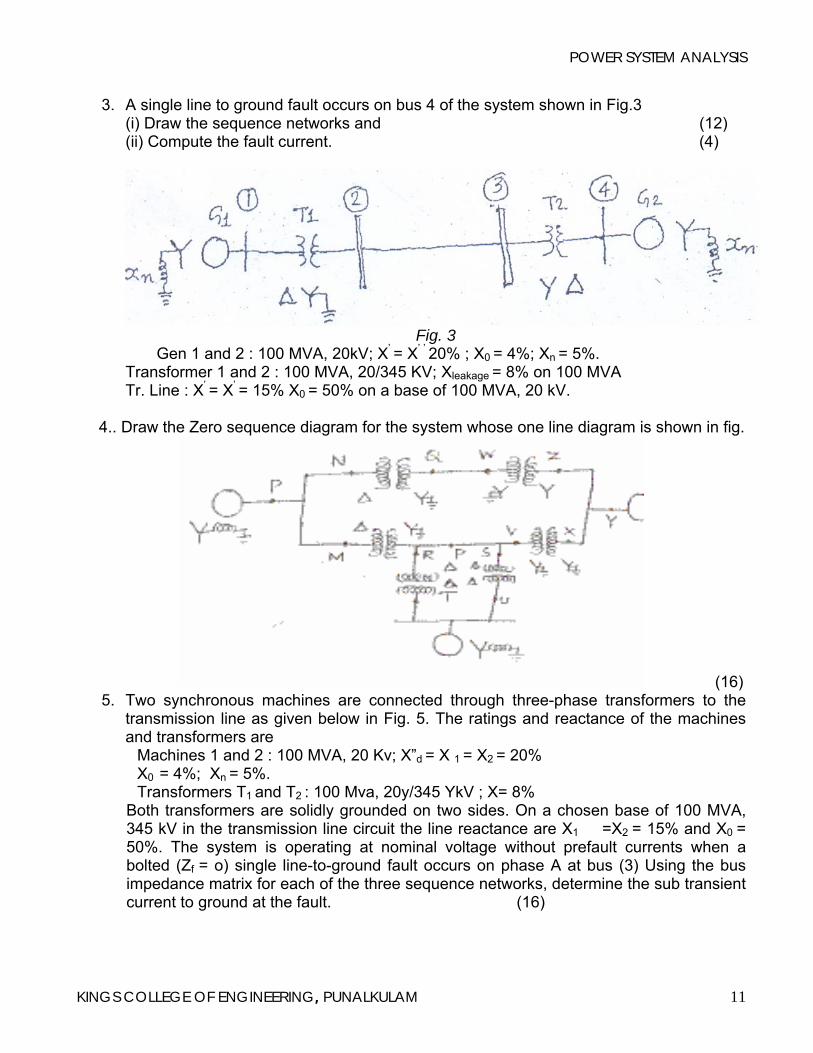
3. A single line to ground fault occurs on bus 4 of the system shown in Fig.3 (i) Draw the sequence networks and (12) (ii) Compute the fault current. (4)
Fig. 3
Gen 1 and 2 : 100 MVA, 20kV; X’ = X’ ’ 20% ; X0 = 4%; Xn = 5%. Transformer 1 and 2 : 100 MVA, 20/345 KV; Xleakage = 8% on 100 MVA Tr. Line : X’ = X’ = 15% X0 = 50% on a base of 100 MVA, 20 kV.
4.. Draw the Zero sequence diagram for the system whose one line diagram is shown in fig.
(16) 5. Two synchronous machines are connected through three-phase transformers to the
transmission line as given below in Fig. 5. The ratings and reactance of the machines and transformers are
Machines 1 and 2 : 100 MVA, 20 Kv; X”d = X 1 = X2 = 20% X0 = 4%; Xn = 5%. Transformers T1 and T2 : 100 Mva, 20y/345 YkV ; X= 8%
Both transformers are solidly grounded on two sides. On a chosen base of 100 MVA, 345 kV in the transmission line circuit the line reactance are X1 =X2 = 15% and X0 = 50%. The system is operating at nominal voltage without prefault currents when a bolted (Zf = o) single line-to-ground fault occurs on phase A at bus (3) Using the bus impedance matrix for each of the three sequence networks, determine the sub transient current to ground at the fault. (16)
KINGS COLLEGE OF ENGINEERING, PUNALKULAM 11
POWER SYSTEM ANALYSIS
Fig.5
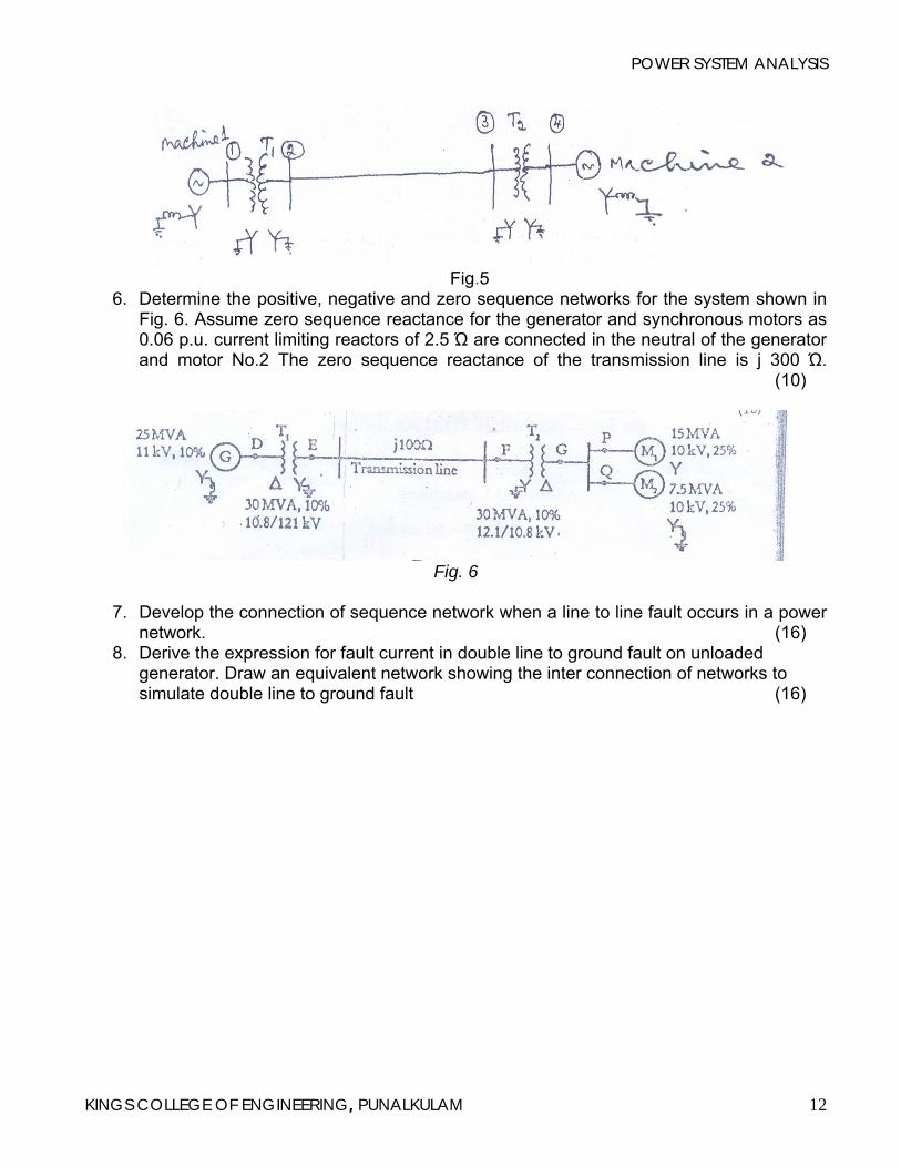
6. Determine the positive, negative and zero sequence networks for the system shown in Fig. 6. Assume zero sequence reactance for the generator and synchronous motors as 0.06 p.u. current limiting reactors of 2.5 Ώ are connected in the neutral of the generator and motor No.2 The zero sequence reactance of the transmission line is j 300 Ώ. (10)
Fig. 6
7. Develop the connection of sequence network when a line to line fault occurs in a power
network. (16) 8. Derive the expression for fault current in double line to ground fault on unloaded
generator. Draw an equivalent network showing the inter connection of networks to simulate double line to ground fault (16)
KINGS COLLEGE OF ENGINEERING, PUNALKULAM 12
POWER SYSTEM ANALYSIS
UNIT- V - POWER SYSTEM STABILITY
PART - A
1. On what basis do you conclude that a given synchronous machine has lost stability 2. Define infinite bus in a power system. 3. What is power system stability? 4. State equal area criterion. 5. Write the swing equation used for stability analysis of power system. 6. Write any two assumptions made to simplify the transient Stability problems. 7. Write the swing-equation for a single synchronous machine connected to an infinite bus 8. Write the concept of critical clearing angle. 9. Define steady state stability limit. 10. State equal area criterion. 11. In a 3-machine system having ratings S1 S2 and S3 and inertia constants M1 M2 and M3,
what is inertia constant M and H of the equivalent system? 12. List any two methods of improving the transient stability limit of power system. 13. Define swing curve. What is the use of swing curve? 14. Write the power-angle equation of a synchronous machine connected to an Infinite bys
and also the expression for maximum power transferable to the bus. 15. Define critical clearing time.
PART- B
1. Derive swing equation used for stability studies in power system. (16) 2. Explain the modified Euler method of analyzing multi machine power system for stability
with a neat flow chart. (16) 3. (i) Derive swing equation for a synchronous machine. (8)
(ii) A 50 Hz generator is delivering 50% of the power that it is capable of delivering through a transmission line to an infinite bus. A fault occurs that increases the reactance between the generator and the infinite bus to 500% of the value before the fault. When the fault is isolated, the maximum power that can be delivered is 75% of the original maximum value. Determine the critical clearing angle for the condition described. (8)
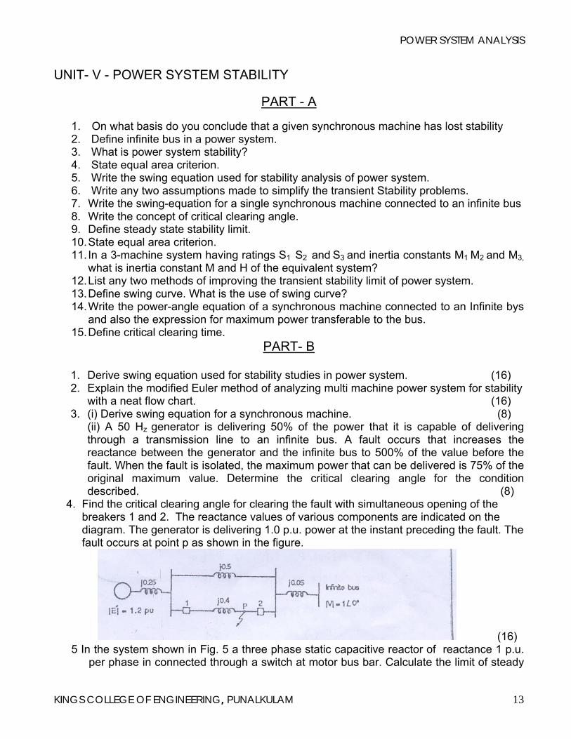
4. Find the critical clearing angle for clearing the fault with simultaneous opening of the breakers 1 and 2. The reactance values of various components are indicated on the diagram. The generator is delivering 1.0 p.u. power at the instant preceding the fault. The fault occurs at point p as shown in the figure.
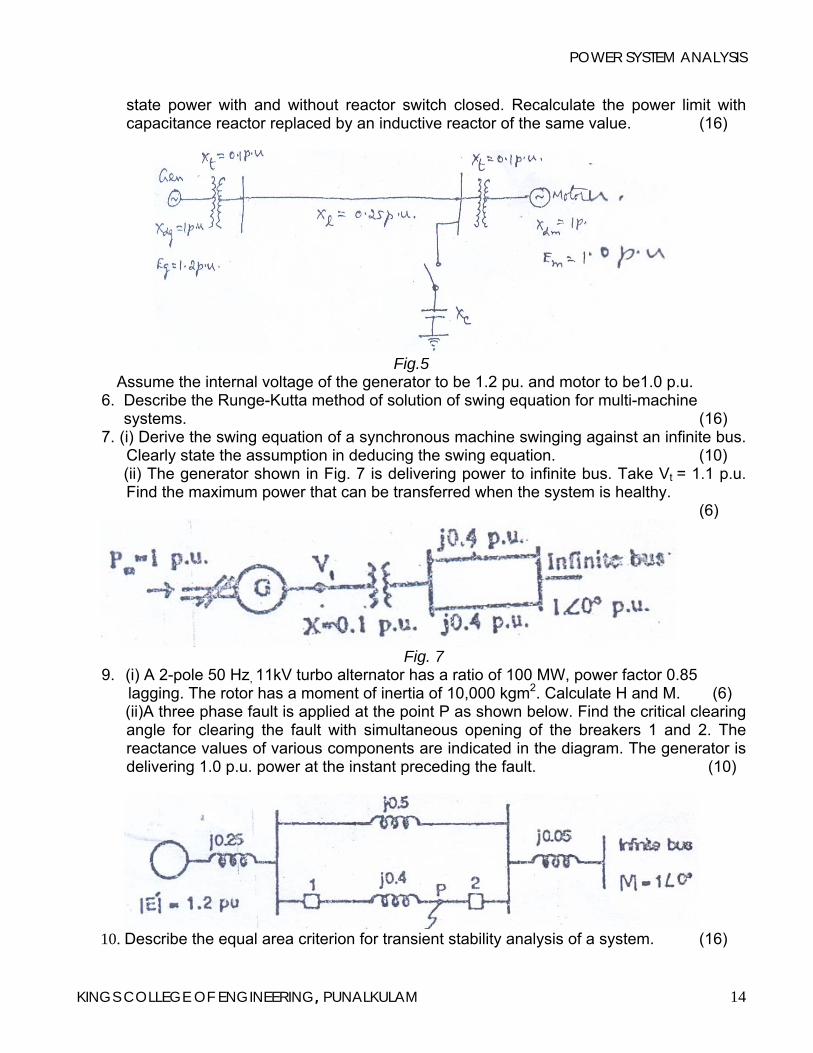
(16) 5 In the system shown in Fig. 5 a three phase static capacitive reactor of reactance 1 p.u.
per phase in connected through a switch at motor bus bar. Calculate the limit of steady
KINGS COLLEGE OF ENGINEERING, PUNALKULAM 13
POWER SYSTEM ANALYSIS
KINGS COLLEGE OF ENGINEERING, PUNALKULAM 14
state power with and without reactor switch closed. Recalculate the power limit with capacitance reactor replaced by an inductive reactor of the same value. (16)
Fig.5
Assume the internal voltage of the generator to be 1.2 pu. and motor to be1.0 p.u. 6. Describe the Runge-Kutta method of solution of swing equation for multi-machine systems. (16) 7. (i) Derive the swing equation of a synchronous machine swinging against an infinite bus.
Clearly state the assumption in deducing the swing equation. (10) (ii) The generator shown in Fig. 7 is delivering power to infinite bus. Take Vt = 1.1 p.u.
Find the maximum power that can be transferred when the system is healthy. (6)
Fig. 7
9. (i) A 2-pole 50 Hz, 11kV turbo alternator has a ratio of 100 MW, power factor 0.85 lagging. The rotor has a moment of inertia of 10,000 kgm2. Calculate H and M. (6)
(ii)A three phase fault is applied at the point P as shown below. Find the critical clearing angle for clearing the fault with simultaneous opening of the breakers 1 and 2. The reactance values of various components are indicated in the diagram. The generator is delivering 1.0 p.u. power at the instant preceding the fault. (10)
10. Describe the equal area criterion for transient stability analysis of a system. (16)


![OT Survey I Kings. English Location of Kings in Canon Hebrew [Historical Books] Joshua Joshua Judges Judges Ruth Ruth Samuel Samuel Kings Kings Chronicles](https://img.pdfslide.net/doc/110x75/56649e155503460f94affa26/ot-survey-i-kings-english-location-of-kings-in-canon-hebrew-historical-books.jpg)