Embed Size (px)
Citation preview
Topologies of Electrical Power Systems
45
Power System Engineering. Juergen Schlabbach and Karl-Heinz RofalskiCopyright © 2008 WILEY-VCH Verlag GmbH & Co. KGaA, WeinheimISBN: 978-3-527-40759-0
5
5.1 Development of Power Systems
The fi rst three - phase alternating current transmission system was built in the year 1891 in Germany on the occasion of the International Electrotechnical Fair. The electrical energy of a hydro power plant with rated power of 140 kW, located in Lauffen on the river Neckar, was transmitted over 175 km by a single - circuit three - phase overhead transmission line, voltage around 14 kV, 40 cycles per second, to the Electrotechnical Fair exhibition in Frankfurt/Main.
Starting from small isolated systems in urban areas, the three - phase AC system became generally accepted throughout the world. Different voltage levels are coupled by transformers from the low - voltage system to an extra - high - voltage level up to 1500 kV. Electrical power systems spread across continents and through DC links also connect different continents or power systems with different frequencies.
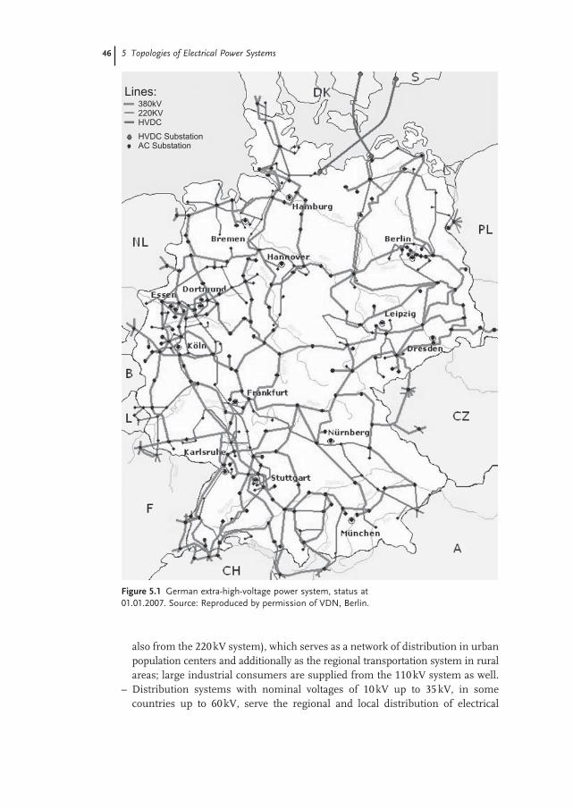
The power system of the Federal Republic of Germany, as represented in Figure 5.1 , included the following at the end of the year 2006 [9] :
– 1 671 300 km electric circuit length, comprising – 1 067 100 km with U n = 0.4 kV – 493 000 km with U n = 6 kV – 60 kV – 111 200 km with U n > 60 kV
– 566 300 transformers with total apparent power 839 200 MVA.
The power system in Germany can be characterized into three different sub-systems according to its tasks.
– The high - voltage transmission grid, the UCTE grid, in the whole of Europe connects the large power stations and the main consumer centers. Its major task is the transportation of electrical energy over long distances under normal and emergency conditions, for example, in case of major outages of power stations. The nominal system voltage is 400 kV (also referred to as 380 kV); some 220 kV lines still exist.
– The sub - transmission systems or regional distribution systems are formed in Germany by the 110 kV network (supplied from the 380 kV system and partly
46 5 Topologies of Electrical Power Systems
Figure 5.1 German extra - high - voltage power system, status at 01.01.2007. Source: Reproduced by permission of VDN, Berlin.
Lines:380kV220KVHVDC
HVDC SubstationAC Substation
also from the 220 kV system), which serves as a network of distribution in urban population centers and additionally as the regional transportation system in rural areas; large industrial consumers are supplied from the 110 kV system as well.
– Distribution systems with nominal voltages of 10 kV up to 35 kV, in some countries up to 60 kV, serve the regional and local distribution of electrical
energy at different voltage levels depending upon load density and type of consumer. Special customers such as industrial installations are supplied at higher voltage levels, for example, 10 kV, than standard tariff customers who are supplied uniformly with the rated voltage of 400 V.
Due to the increasing utilization of “ green - energy, ” power stations are connected to different voltage levels from 0.4 kV (small photovoltaic installations) up to high voltages (wind power farms), the tasks of the different voltage levels cannot be defi ned so clearly in the future.
5.2 Recommended Voltage Levels
Nominal voltages in power systems are recommended in IEC 60038. Table 5.1 outlines the appropriate voltage levels as applicable in Germany. In addition to the nominal voltage, typical application and supply tasks are mentioned as well.
Table 5.1 Recommended system voltages according to IEC 60038 as applicable in German power systems.
Common name
Nominal system voltage
Supply task Remarks
Low - voltage (LV)
400 V/230 V Household customers Small industrial consumers
IEC 60038 Table I
500 V Supply of motors in industry Not mentioned in IEC 60038
Medium - voltage (MV)
6 kV HV - motors in industry and power stations IEC 60038 Table III
10 kV Urban supply, industrial power systems
20 kV Rural supply, industrial power systems
30 kV Industrial supply (electrolysis, thermal processes) Rural power supply
Not mentioned in IEC 60038
High - voltage (HV)
110 kV Urban transport and sub - transmission systems
IEC 60038 Table IV
220 kV Transmission systems (decreasing importance)
380 kV (400 kV) UCTE transmission system IEC 60038 Table V Defi nition of highest voltage of equipment U bmax = 420 kV
5.2 Recommended Voltage Levels 47
48 5 Topologies of Electrical Power Systems
It should be mentioned in this respect that the existence of the different voltage levels is due partially to historical development. Economic studies indicate that a suitable grading of the individual voltage levels in MV and HV systems should be in the order of 1 : 3 to 1 : 7, that is, 10 kV or 20 kV in MV systems, 110 kV and 400 kV in HV systems and 1200 kV in EHV systems, as far as applicable.
5.3 Topology of Power Systems
Power systems are constructed and operated as
– Radial systems or – Ring - main systems or – Meshed systems.
Additional criteria for distinction can be defi ned, such as the number and kind of feeders from supplying system level, the number and arrangement of lines and the reserve capability of the system to cover loss of load. The three system topolo-gies are constructed and operated at all voltage levels. In the context of the sections below, the following defi nitions are used:
Feeder Outgoing connection of any overhead line or cable from a MV or LV substation
Gridstation Switchyard including busbars, transformers and outgoing feeders to the EHV level
Substation Switchyard including busbars, transformers and outgoing feeders to the HV level
Station Switchyard including busbars, transformers and outgoing feeders to the MV level
Primary Switchyard including busbars, transformers and outgoing feeders to the LV level
Line Any overhead line or cable of any voltage level .
5.3.1 Radial Systems
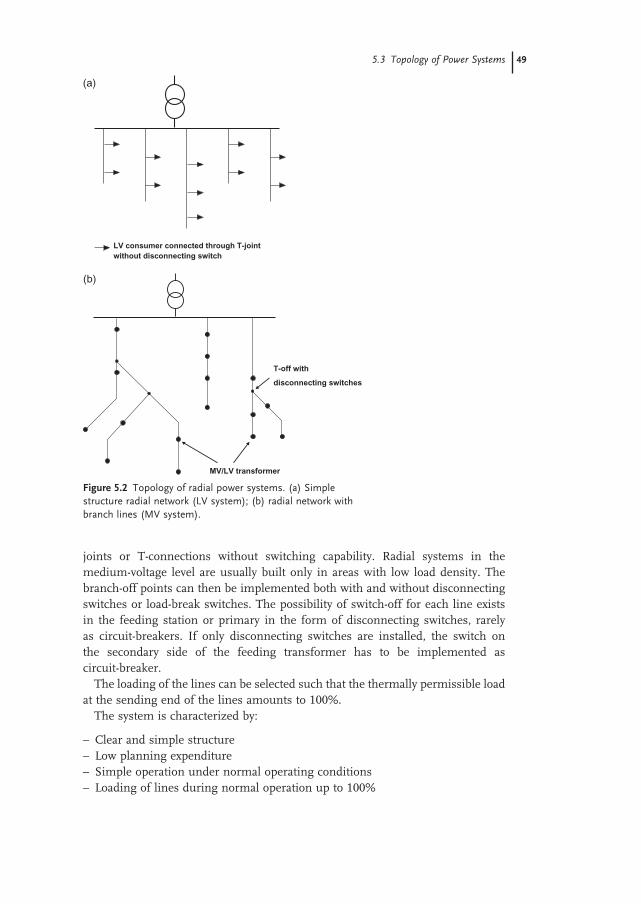
The simplest system confi guration, the radial system, can be found particularly at the low - voltage and the medium - voltage levels. The individual feeders or lines, connected to the primary or station, connect the primaries by radial feeders, as represented in Figure 5.2 a. Branching of the lines is possible and in fact usual (Figure 5.2 b). This network confi guration is suitable for areas with low load density and is also used for the connection of bulk loads. In this case the system is called a connection system. The advantages of the simple topology and low capital invest-ment cost have to be compared with the disadvantage that, in case of failure of lines, the load of the faulted lines cannot be supplied. The branch - off points in the low - voltage system are sometimes implemented in the form of branch - off
5.3 Topology of Power Systems 49
joints or T - connections without switching capability. Radial systems in the medium - voltage level are usually built only in areas with low load density. The branch - off points can then be implemented both with and without disconnecting switches or load - break switches. The possibility of switch - off for each line exists in the feeding station or primary in the form of disconnecting switches, rarely as circuit - breakers. If only disconnecting switches are installed, the switch on the secondary side of the feeding transformer has to be implemented as circuit - breaker.
The loading of the lines can be selected such that the thermally permissible load at the sending end of the lines amounts to 100%.
The system is characterized by:
– Clear and simple structure – Low planning expenditure – Simple operation under normal operating conditions – Loading of lines during normal operation up to 100%
Figure 5.2 Topology of radial power systems. (a) Simple structure radial network (LV system); (b) radial network with branch lines (MV system).
(a)
LV consumer connected through T-jointwithout disconnecting switch
(b)
MV/LV transformer
T-off with
disconnecting switches
50 5 Topologies of Electrical Power Systems
– No reserve for loss of lines – Low investment cost – Maintenance cost rather small – System losses comparatively high; losses cannot be minimized – Voltage profi le not very good; distinct voltage drop between the feeding and the
receiving end of the lines – Flexibility for changed load conditions is comparatively small – Reserve for losses of the feeding MV transformer usually missing – Standardization of cross - sections of lines possible, but not advisable – Protection usually only with overcurrent relays at the feeder, in MV systems,
sometimes also with circuit - breakers, in LV systems with fuses – Typical application in MV systems up to 60 kV with small load densities up to
approximately 1 MW km − 2 , typically in low - voltage systems.
The reliability and/or the reserve capability of radial systems can only be improved in principle if another concept is used: the pure radial system is con-verted into a ring - main system or even a meshed system.
5.3.2 Ring - Main Systems
Ring - main systems are common in the medium - voltage range. A large variety of ring - main systems are in operation with respect to permissible loading of the lines, reserve capability against outages, different arrangement of the feeding station and supply reliability.
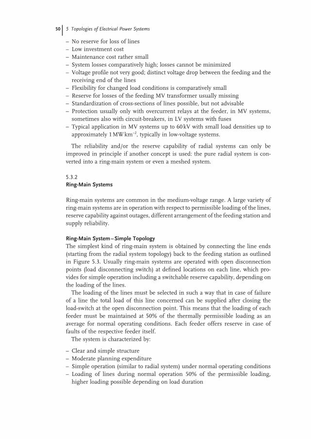
Ring - Main System – Simple Topology The simplest kind of ring - main system is obtained by connecting the line ends (starting from the radial system topology) back to the feeding station as outlined in Figure 5.3 . Usually ring - main systems are operated with open disconnection points (load disconnecting switch) at defi ned locations on each line, which pro-vides for simple operation including a switchable reserve capability, depending on the loading of the lines.
The loading of the lines must be selected in such a way that in case of failure of a line the total load of this line concerned can be supplied after closing the load - switch at the open disconnection point. This means that the loading of each feeder must be maintained at 50% of the thermally permissible loading as an average for normal operating conditions. Each feeder offers reserve in case of faults of the respective feeder itself.
The system is characterized by:
– Clear and simple structure – Moderate planning expenditure – Simple operation (similar to radial system) under normal operating conditions – Loading of lines during normal operation 50% of the permissible loading,
higher loading possible depending on load duration
5.3 Topology of Power Systems 51
– Reserve for outage of each line section given by the line itself – Investment cost not very high; reduction possible, if circuit - breakers are omitted;
in this case one circuit - breaker has to be installed on the secondary side of the feeding transformer
– Maintenance cost rather low – System losses can be minimized by changing the location of the open
disconnection point
Figure 5.3 Ring - main system simple topology. (a) Arrangement with limited reserve in feeding station; (b) arrangement with reserve to cover outages in the feeding station.
(a)
// Disconnection point (n.o.)
• MV/LV transformer connected through fuse or disconnecting switch
• MV/LV transformer connected through fuse or disconnecting switch
(b)
// Disconnection point (n.o.)
52 5 Topologies of Electrical Power Systems
– Voltage profi le can be optimized, differences between feeding and receiving end of the lines depend on the location of the open disconnection point
– Flexibility to respond to changing load conditions – Reserve for outage of feeding transformer or bus section usually available if an
arrangement is selected as in Figure 5.3 b – Standardization of cross - sections of the lines is given (usually only one cross -
section shall be used) – Feeder protection can be realized with overcurrent protection – Application in medium - voltage systems up to 35 kV, in case of high load density,
in principle also in low - voltage systems.
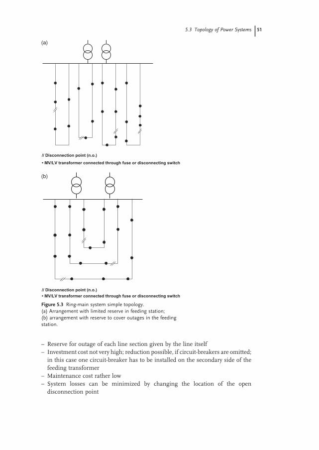
Ring - Main System with Remote Station (Without Supply) Connecting the individual lines of the system at the receiving end to a station without infeed from a higher voltage supply level forms a ring - main system as outlined in Figure 5.4 . Normal operation condition is with open disconnection point, thus forming a radial system. Load - switches are also installed to select suit-able disconnection point locations similarly to the ring - main system shown in Figure 5.3 . The remote station should always be kept energized, so as to guarantee a quick switchover of line sections in case of outages.
The permissible loading of individual lines can be above 50% of the thermally permissible load of a line, depending on the loading of all lines. In case of outage of any feeder, the load will be supplied by separation of the faulted line section through the remote station by one or more lines connected to it. This type of ring - main system with remote station can be seen as an intermediate step of system development between a pure radial system and a ring - main system with a feeding remote station (see below).
Figure 5.4 Ring - main system with remote station (without supply).
// Disconnection point (n.o.)
• MV/LV transformer connected through fuse or disconnecting switch
5.3 Topology of Power Systems 53
The system is characterized by:
– Clear and simple structure – Moderate expenditure for planning – Simple operation under normal operating conditions – Loading of lines under normal operating conditions more than 50% of
permissible thermal loading – Reserve for outages available depending on the preloading of the remaining
lines – Investment cost in the medium range; reduction possible if a topology without
circuit - breakers for the feeders is selected. In this case one circuit - breaker has to be installed on the secondary side of the feeding transformer
– Maintenance cost rather low – Power system losses cannot be minimized – Voltage profi le in the system not optimal, differences between feeding station
and remote station are signifi cant – Flexibility to respond to changed load conditions – Reserve for outage of the feeding MV transformer usually available – Standardization of cross - sections of all lines given (usually one cross - section
used) – Feeder protection can be realized with overcurrent protection – Application in medium - voltage systems up to 35 kV, also in case of medium
load density, in principle also in low - voltage systems.
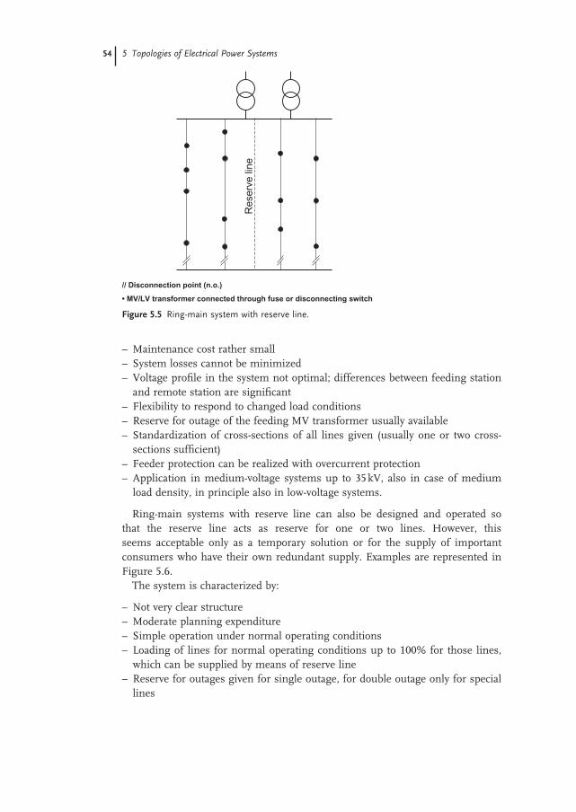
Ring - Main System with Reserve Line If a separate line between the feeding station and the remote station is constructed, without supplying load through this line under normal operating conditions, the system performance is signifi cantly improved by this reserve line. The general topology is indicated in Figure 5.5 . If the cross - section of the reserve line is chosen identical to the other lines, the loading of the lines can be increased to as much as 100%. The outage of one line is covered under the system topology. The second line outage is no longer covered, however; to achieve this, the reserve line must have a larger cross - section.
The system is characterized by:
– Clear and simple structure – Moderate planning expenditure – Simple operation under normal operating conditions – Loading of lines under normal operating conditions up to 100%, resulting in
outage reserve for one line – Reserve for outages of more than one line depending on preloading conditions
of the feeders or on the cross - section of the reserve line – Investment cost within the medium range but extra cost for reserve line;
reduction possible if circuit - breakers for the feeders are omitted. In this case one circuit - breaker has to be installed on the secondary side of the feeding transformer
54 5 Topologies of Electrical Power Systems
– Maintenance cost rather small – System losses cannot be minimized – Voltage profi le in the system not optimal; differences between feeding station
and remote station are signifi cant – Flexibility to respond to changed load conditions – Reserve for outage of the feeding MV transformer usually available – Standardization of cross - sections of all lines given (usually one or two cross -
sections suffi cient) – Feeder protection can be realized with overcurrent protection – Application in medium - voltage systems up to 35 kV, also in case of medium
load density, in principle also in low - voltage systems.
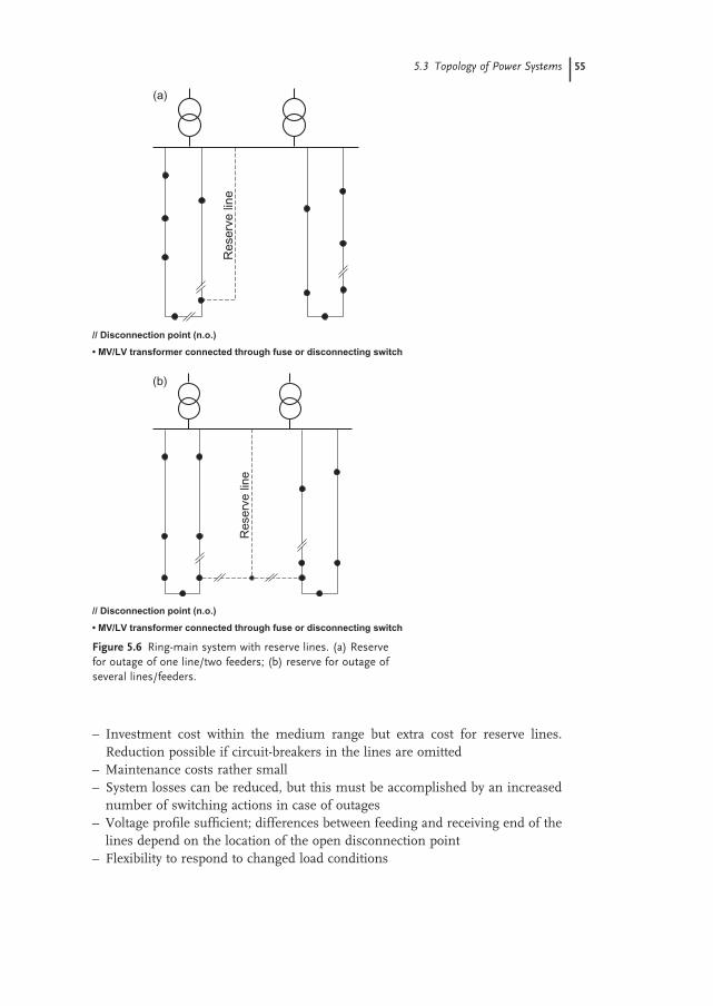
Ring - main systems with reserve line can also be designed and operated so that the reserve line acts as reserve for one or two lines. However, this seems acceptable only as a temporary solution or for the supply of important consumers who have their own redundant supply. Examples are represented in Figure 5.6 .
The system is characterized by:
– Not very clear structure – Moderate planning expenditure – Simple operation under normal operating conditions – Loading of lines for normal operating conditions up to 100% for those lines,
which can be supplied by means of reserve line – Reserve for outages given for single outage, for double outage only for special
lines
Figure 5.5 Ring - main system with reserve line.
Res
erve
line
// Disconnection point (n.o.)
• MV/LV transformer connected through fuse or disconnecting switch
5.3 Topology of Power Systems 55
– Investment cost within the medium range but extra cost for reserve lines. Reduction possible if circuit - breakers in the lines are omitted
– Maintenance costs rather small – System losses can be reduced, but this must be accomplished by an increased
number of switching actions in case of outages – Voltage profi le suffi cient; differences between feeding and receiving end of the
lines depend on the location of the open disconnection point – Flexibility to respond to changed load conditions
Figure 5.6 Ring - main system with reserve lines. (a) Reserve for outage of one line/two feeders; (b) reserve for outage of several lines/feeders.
Res
erve
line
(a)
// Disconnection point (n.o.)
• MV/LV transformer connected through fuse or disconnecting switch
Res
erve
line
(b)
// Disconnection point (n.o.)
• MV/LV transformer connected through fuse or disconnecting switch
56 5 Topologies of Electrical Power Systems
– Reserve for loss of the feeding MV transformer usually available – Standardization of cross - sections given (usually one or two cross - sections are
suffi cient) – Feeder protection can be realized with overcurrent protection – Application in medium - voltage systems up to 35 kV, also in case of medium
load density, in principle also in low - voltage systems.
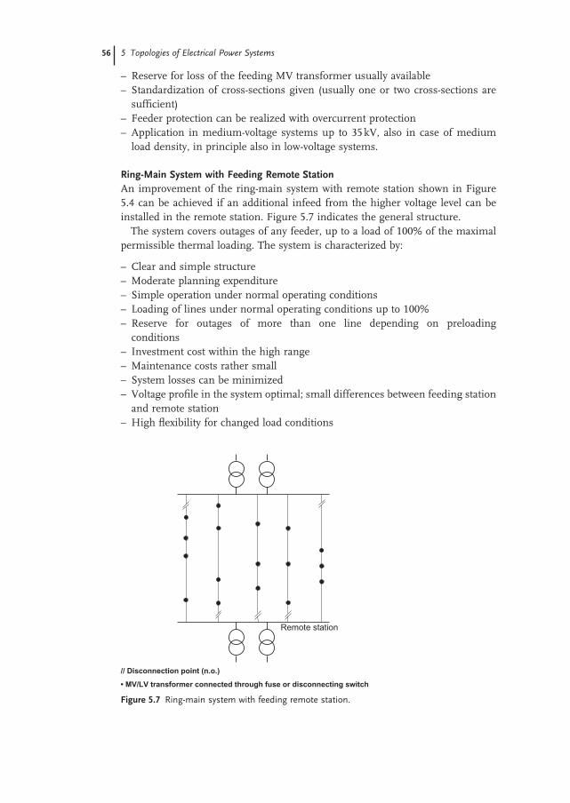
Ring - Main System with Feeding Remote Station An improvement of the ring - main system with remote station shown in Figure 5.4 can be achieved if an additional infeed from the higher voltage level can be installed in the remote station. Figure 5.7 indicates the general structure.
The system covers outages of any feeder, up to a load of 100% of the maximal permissible thermal loading. The system is characterized by:
– Clear and simple structure – Moderate planning expenditure – Simple operation under normal operating conditions – Loading of lines under normal operating conditions up to 100% – Reserve for outages of more than one line depending on preloading
conditions – Investment cost within the high range – Maintenance costs rather small – System losses can be minimized – Voltage profi le in the system optimal; small differences between feeding station
and remote station – High fl exibility for changed load conditions
Figure 5.7 Ring - main system with feeding remote station.
Remote station
// Disconnection point (n.o.)
• MV/LV transformer connected through fuse or disconnecting switch
5.3 Topology of Power Systems 57
– Reserve for outage of the feeding MV transformer and station is available – Standardization of cross - sections of all lines given (usually one cross - section is
suffi cient) – Feeder protection can be realized with overcurrent protection – Application in medium - voltage systems up to 35 kV, also in case of high load
density, in principle also in low - voltage systems.
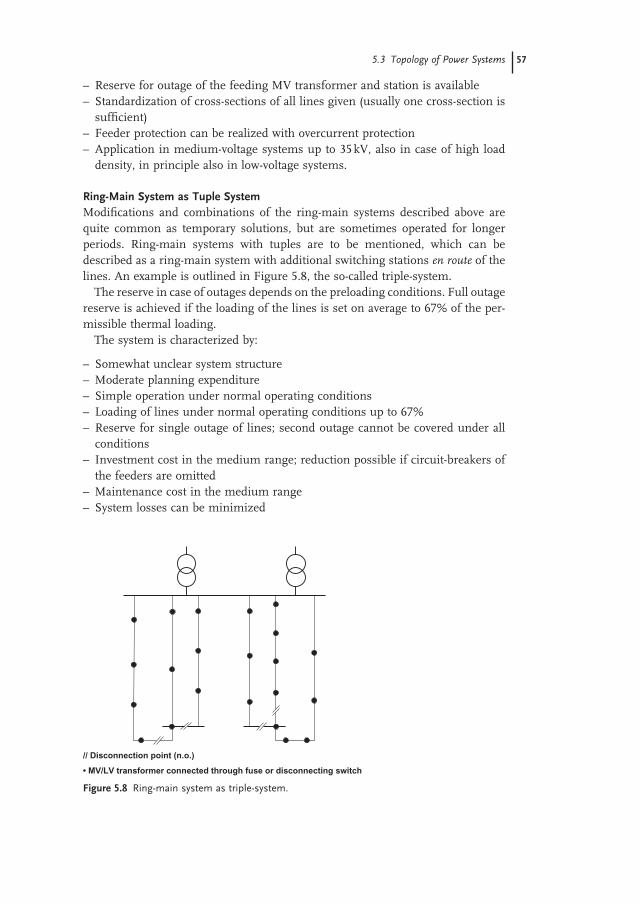
Ring - Main System as Tuple System Modifi cations and combinations of the ring - main systems described above are quite common as temporary solutions, but are sometimes operated for longer periods. Ring - main systems with tuples are to be mentioned, which can be described as a ring - main system with additional switching stations en route of the lines. An example is outlined in Figure 5.8 , the so - called triple - system.
The reserve in case of outages depends on the preloading conditions. Full outage reserve is achieved if the loading of the lines is set on average to 67% of the per-missible thermal loading.
The system is characterized by:
– Somewhat unclear system structure – Moderate planning expenditure – Simple operation under normal operating conditions – Loading of lines under normal operating conditions up to 67% – Reserve for single outage of lines; second outage cannot be covered under all
conditions – Investment cost in the medium range; reduction possible if circuit - breakers of
the feeders are omitted – Maintenance cost in the medium range – System losses can be minimized
Figure 5.8 Ring - main system as triple - system.
// Disconnection point (n.o.)
• MV/LV transformer connected through fuse or disconnecting switch
58 5 Topologies of Electrical Power Systems
– Voltage profi le suffi cient; differences between feeding and receiving end of the lines depend on the location of the open disconnection point
– Flexibility for changed load conditions – Reserve for outage of the feeding MV transformer usually available – Standardization of cross - sections of all lines given (usually one or two
cross - sections) – Feeder protection can be realized with overcurrent protection – Application in medium - voltage systems up to 35 kV with medium load
density.
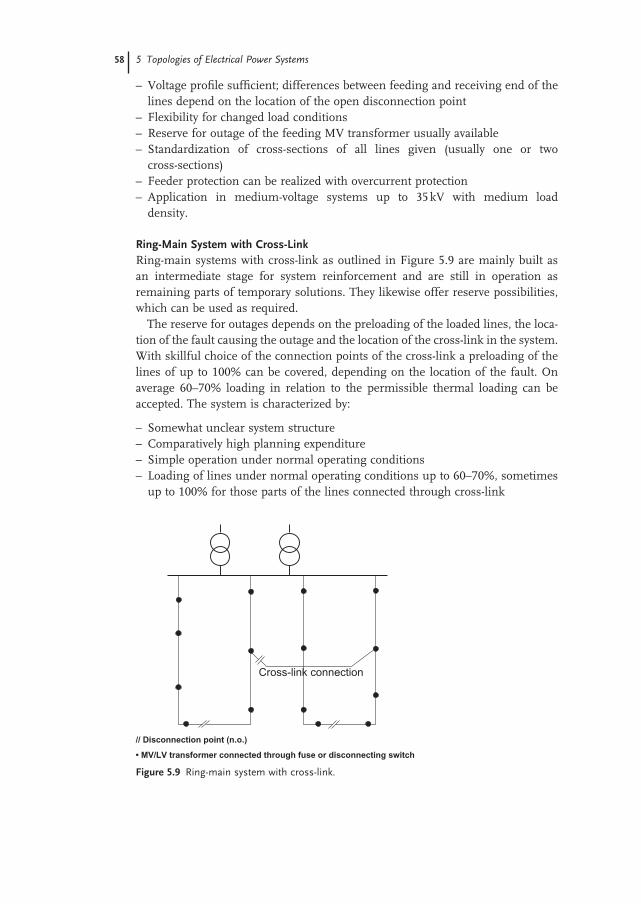
Ring - Main System with Cross - Link Ring - main systems with cross - link as outlined in Figure 5.9 are mainly built as an intermediate stage for system reinforcement and are still in operation as remaining parts of temporary solutions. They likewise offer reserve possibilities, which can be used as required .
The reserve for outages depends on the preloading of the loaded lines, the loca-tion of the fault causing the outage and the location of the cross - link in the system. With skillful choice of the connection points of the cross - link a preloading of the lines of up to 100% can be covered, depending on the location of the fault. On average 60 – 70% loading in relation to the permissible thermal loading can be accepted. The system is characterized by:
– Somewhat unclear system structure – Comparatively high planning expenditure – Simple operation under normal operating conditions – Loading of lines under normal operating conditions up to 60 – 70%, sometimes
up to 100% for those parts of the lines connected through cross - link
Figure 5.9 Ring - main system with cross - link.
Cross-link connection
// Disconnection point (n.o.)
• MV/LV transformer connected through fuse or disconnecting switch
5.3 Topology of Power Systems 59
– Reserve for single outage of lines given, depending on the preload; second outage cannot be covered under all conditions
– Investment cost within the medium range, but extra cost for the cross - link; reduction possible if circuit - breakers in the feeders are omitted
– Maintenance cost in the medium range – System losses can be minimized – Voltage profi le suffi cient; differences between feeding and receiving end of the
lines depend on the location of the open disconnection point – Flexibility for changed load conditions not very high – Reserve for outage of the feeding MV transformer usually available – Standardization of cross - sections of all lines given (usually one or two
cross - sections) – Feeder protection can be realized with overcurrent protection – Application in medium - voltage systems up to 35 kV with medium load density.
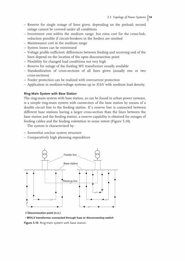
Ring - Main System with Base Station The ring - main system with base station, as can be found in urban power systems, is a simple ring - main system with connection of the base station by means of a double circuit line to the feeding station. If a reserve line is connected between different base stations having a larger cross - section than the lines between the base station and the feeding station, a reserve capability is obtained for outages of feeding cables and the feeding substation to some extent (Figure 5.10 ) .
The system is characterized by:
– Somewhat unclear system structure – Comparatively high planning expenditure
Figure 5.10 Ring - main system with base station.
Reserve line
Feeder line
Base station
// Disconnection point (n.o.)
• MV/LV transformer connected through fuse or disconnecting switch
60 5 Topologies of Electrical Power Systems
– Simple operation under normal operating conditions – Loading of lines under normal operating conditions up to 67%, sometimes up
to 100% – Reserve for single outage of lines given by each line itself; reserve for the feeding
line given by parallel line – Investment cost in the high range due to the additional base station – Maintenance cost high – System losses can be minimized – Voltage profi le suffi cient; differences between feeding and receiving end of the
lines depend on the location of the open disconnection point – Flexibility for changed load conditions – Reserve for outage of the feeding MV transformer is available – Standardization of cross - sections of lines (usually two cross - sections are suffi cient) – Feeder protection can be realized with overcurrent protection – Application in medium - voltage systems up to 35 kV with high load density.
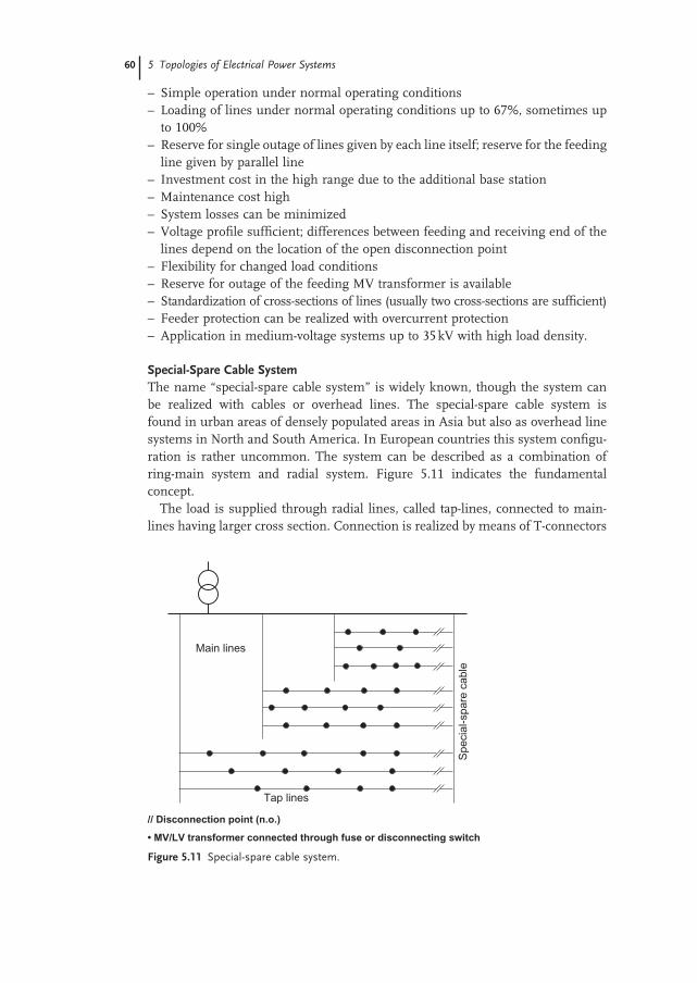
Special - Spare Cable System The name “ special - spare cable system ” is widely known, though the system can be realized with cables or overhead lines. The special - spare cable system is found in urban areas of densely populated areas in Asia but also as overhead line systems in North and South America. In European countries this system confi gu-ration is rather uncommon. The system can be described as a combination of ring - main system and radial system. Figure 5.11 indicates the fundamental concept.
The load is supplied through radial lines, called tap - lines, connected to main - lines having larger cross section. Connection is realized by means of T - connectors
Figure 5.11 Special - spare cable system.
Tap lines
Main lines
Spe
cial
-spa
re c
able
// Disconnection point (n.o.)
• MV/LV transformer connected through fuse or disconnecting switch
5.3 Topology of Power Systems 61
in overhead line systems and special T - joints in cable systems. A spare cable, called the special - spare cable, with the same cross - section as the main cable is connected to the other end of the tap lines by T - connectors or T - joints. The special - spare cable does not supply load under normal operating conditions but is kept energized. Reserve for outages by the special - spare cable is only given for outages of the tap lines and only to a minor extent for outage of a main line. Generally one can assume the loading of the tap lines as up to 100% of the thermal permissible loading.
The system is characterized by:
– Simple and clear structure – Moderate planning expenditure – Easy operation under normal operating conditions – Loading of the lines under normal operating conditions 100% for tap lines and
up to 70% for the main lines, dependent on the preload conditions and the cross - section of main lines and special - spare cable
– Reserve for line outage depends on cable layout (cross - section) and loading conditions
– Investment cost comparatively low if disconnecting load - switches are omitted – Maintenance cost rather small – System losses comparatively high and cannot be minimized – Voltage profi le only moderate, partially large differences between feeding and
receiving end of the tap - lines – Flexibility for changed load conditions is small – Reserve for losses of the feeding MV transformer usually available – Standardization of cross - sections of line possible (at least two or three different
cross - sections are needed) – Protection usually only with overcurrent protection for the main lines – Advisable application in medium - voltage systems up to 35 kV with small load
densities; however, the system is widely used in urban power systems.
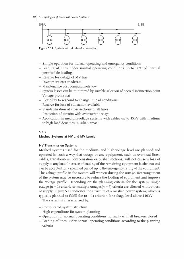
Double - T Connection The double - T connection concept in MV systems is found especially in centers of large cities with high load density. The primaries, feeding the LV systems, are connected to two independent lines which are connected to different substations. High reliability is achieved by this scheme compared with the ring - main systems described so far (Figures 5.4 and 5.5 ). The system can cover any outage of a MV line. A line fault leads to the outage of the complete feeder. If the primaries are connected to the line by three load - switches, the outage of one line results only in the outage of a section of the line. The system can be operated either in open - circuit mode or fed from both primaries, in this case it is more a meshed system than a ring - main system. Figure 5.12 indicates the system structure.
The system is characterized by:
– Simple and clear system structure – Moderate planning expenditure
62 5 Topologies of Electrical Power Systems
– Simple operation for normal operating and emergency conditions – Loading of lines under normal operating conditions up to 60% of thermal
permissible loading – Reserve for outage of MV line – Investment cost moderate – Maintenance cost comparatively low – System losses can be minimized by suitable selection of open disconnection point – Voltage profi le fl at – Flexibility to respond to change in load conditions – Reserve for loss of substation available – Standardization of cross - sections of all lines – Protection of circuits with overcurrent relays – Application in medium - voltage systems with cables up to 35 kV with medium
to high load densities in urban areas.
5.3.3 Meshed Systems at HV and MV Levels
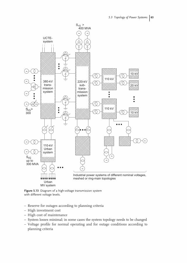
HV Transmission Systems Meshed systems used for the medium - and high - voltage level are planned and operated in such a way that outage of any equipment, such as overhead lines, cables, transformers, compensation or busbar sections, will not cause a loss of supply to any load. Increase of loading of the remaining equipment is obvious and can be accepted for a specifi ed period up to the emergency rating of the equipment. The voltage profi le in the system will worsen during the outage. Rearrangement of the system may be necessary to reduce the loading of equipment and improve the voltage profi le. Depending on the planning criteria for the system, single outage ( n − 1) - criteria or multiple outages( n − k ) - criteria are allowed without loss of supply. Figure 5.13 indicates the structure of a meshed power system, which is typically planned to fulfi ll the ( n − 1) - criterion for voltage level above 110 kV.
The system is characterized by:
– Complicated system structure – High expenditure for system planning – Operation for normal operating conditions normally with all breakers closed – Loading of lines under normal operating conditions according to the planning
criteria
Figure 5.12 System with double - T connection.
S/SA S/SB
5.3 Topology of Power Systems 63
– Reserve for outages according to planning criteria – High investment cost – High cost of maintenance – System losses minimal; in some cases the system topology needs to be changed – Voltage profi le for normal operating and for outage conditions according to
planning criteria
Figure 5.13 Diagram of a high - voltage transmission system with different voltage levels.
SrGup to300 MVA
UrbanMV system
110-kVUrbansystem
~
~
380-kVtrans-
missionsystem
~
~
~
~
rG
220-kVsub-
trans-missionsystem
~~
110 kV
110 kV10 kV
20 kV
10 kV
~~
~
300S >
~
Industrial power systems of different nominal voltages,meshed or ring-main topologies
S >400 MVA
rG
UCTE-system
64 5 Topologies of Electrical Power Systems
– High fl exibility for changed load conditions – No interruption of supply according to planning criteria – Standardization of cross - section and rating of equipment is possible – Protection with distance protection relays or with differential protection – Applicable for HV and EHV systems for high load density.
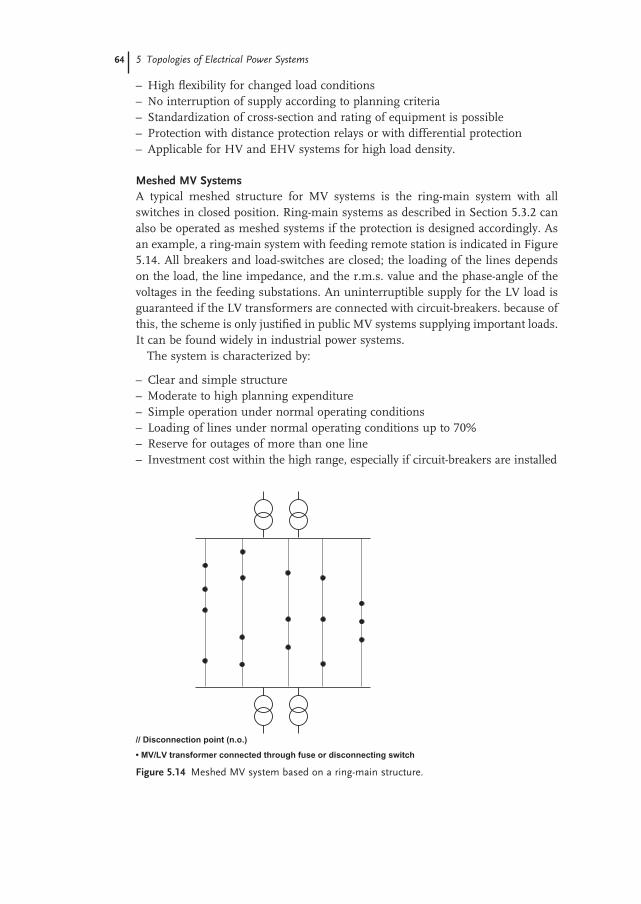
Meshed MV Systems A typical meshed structure for MV systems is the ring - main system with all switches in closed position. Ring - main systems as described in Section 5.3.2 can also be operated as meshed systems if the protection is designed accordingly. As an example, a ring - main system with feeding remote station is indicated in Figure 5.14 . All breakers and load - switches are closed; the loading of the lines depends on the load, the line impedance, and the r.m.s. value and the phase - angle of the voltages in the feeding substations. An uninterruptible supply for the LV load is guaranteed if the LV transformers are connected with circuit - breakers. because of this, the scheme is only justifi ed in public MV systems supplying important loads. It can be found widely in industrial power systems.
The system is characterized by:
– Clear and simple structure – Moderate to high planning expenditure – Simple operation under normal operating conditions – Loading of lines under normal operating conditions up to 70% – Reserve for outages of more than one line – Investment cost within the high range, especially if circuit - breakers are installed
Figure 5.14 Meshed MV system based on a ring - main structure.
// Disconnection point (n.o.)
• MV/LV transformer connected through fuse or disconnecting switch
5.3 Topology of Power Systems 65
– Maintenance costs high – System losses minimal – Voltage profi le in the system optimal; small differences between feeding station
and remote station – High fl exibility for changed load conditions – Reserve for outage of the feeding MV transformer and station available – Standardization of cross - sections of all lines (usually one cross - section is
suffi cient) – Feeder protection usually with distance or differential protection relays – Application in medium - voltage systems up to 35 kV, also in case of high load
density, for the supply of important consumers and in industrial power systems.
5.3.4 Meshed Systems at the LV Level
Meshed systems at the LV level are still found in older installations and in indus-trial power supply. The reliability is very high and multiple outage of equipment is covered with this scheme. The voltage profi le is fl at and the system losses are minimal. Depending on the connection of the feeding primaries, three different types of systems can be distinguished:
– Supply station - by - station – Single - line supply – Multiple - line supply.
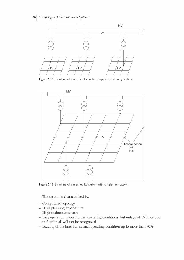
Meshed System Supplied Station - by - Station Figure 5.15 indicates the general structure of such a LV system. Each individual LV system is supplied by one LV transformer. The MV system can be designed as a ring - main system in urban areas as indicated or in rural areas as radial system. The system is safe against outages only at the LV level; outages of LV transformers and of the MV line will lead to a loss of supply.
Single - Line Supply The single - line supply of a LV system is outlined in Figure 5.16 . The meshed LV system is supplied by more than one LV transformer; however, the transformers are connected at MV level to one line only. The system covers outages in the LV system and of the LV transformers. Outages of the MV line will result in a loss of supply.
Multiple - Line Supply A LV system with multiple - line supply is fed by several LV transformers which are connected on the MV side to different lines. The system is safe against outages in the LV system, outages of LV transformers and also outages in the MV system as well if the MV system is designed accordingly. Figure 5.17 indicates the general structure.
66 5 Topologies of Electrical Power Systems
The system is characterized by:
– Complicated topology – High planning expenditure – High maintenance cost – Easy operation under normal operating conditions, but outage of LV lines due
to fuse - break will not be recognized – Loading of the lines for normal operating condition up to more than 70%
Figure 5.15 Structure of a meshed LV system supplied station - by - station.
MV
LV LV LV
Figure 5.16 Structure of a meshed LV system with single - line supply.
MV
LV
Disconnectionpointn.o.
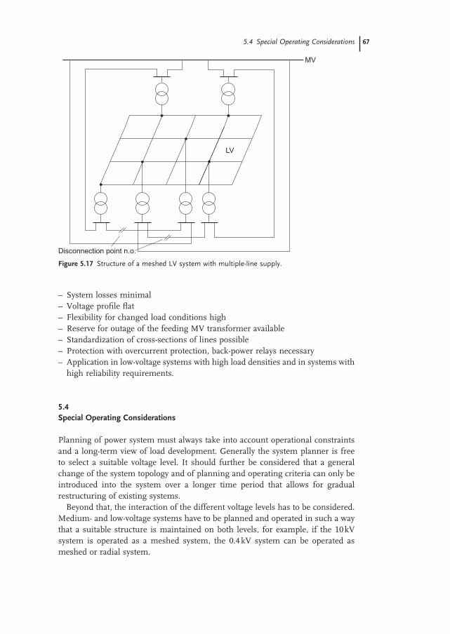
– System losses minimal – Voltage profi le fl at – Flexibility for changed load conditions high – Reserve for outage of the feeding MV transformer available – Standardization of cross - sections of lines possible – Protection with overcurrent protection, back - power relays necessary – Application in low - voltage systems with high load densities and in systems with
high reliability requirements.
5.4 Special Operating Considerations
Planning of power system must always take into account operational constraints and a long - term view of load development. Generally the system planner is free to select a suitable voltage level. It should further be considered that a general change of the system topology and of planning and operating criteria can only be introduced into the system over a longer time period that allows for gradual restructuring of existing systems.
Beyond that, the interaction of the different voltage levels has to be considered. Medium - and low - voltage systems have to be planned and operated in such a way that a suitable structure is maintained on both levels, for example, if the 10 kV system is operated as a meshed system, the 0.4 kV system can be operated as meshed or radial system.
Figure 5.17 Structure of a meshed LV system with multiple - line supply.
MV
LV
Disconnection point n.o.
5.4 Special Operating Considerations 67
68 5 Topologies of Electrical Power Systems
High - voltage transmission systems are operated with few exceptions as meshed systems. The loading of equipment for normal and emergency conditions as well as the losses and the voltage profi le for normal operating and for emergency condi-tions must be determined by load - fl ow calculations. Regarding MV and LV systems that both are operated as meshed systems, the impedances of MV and LV systems normally do not allow any load - fl ow through the LV system. Loading of the LV transformers is determined only by the LV load, and cannot be changed except by changing the system topology. An exact determination of the loading of the LV transformers is diffi cult, as knowledge of the LV load in most cases is based on the energy correlated with typical load curves (see Section 2.6 ).
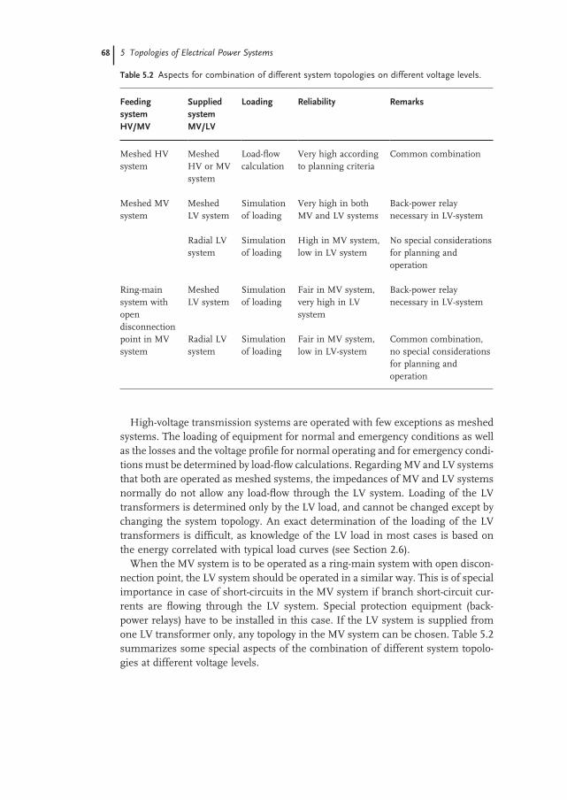
When the MV system is to be operated as a ring - main system with open discon-nection point, the LV system should be operated in a similar way. This is of special importance in case of short - circuits in the MV system if branch short - circuit cur-rents are fl owing through the LV system. Special protection equipment (back - power relays) have to be installed in this case. If the LV system is supplied from one LV transformer only, any topology in the MV system can be chosen. Table 5.2 summarizes some special aspects of the combination of different system topolo-gies at different voltage levels.
Table 5.2 Aspects for combination of different system topologies on different voltage levels.
Feeding system HV/MV
Supplied system MV/LV
Loading Reliability Remarks
Meshed HV system
Meshed HV or MV system
Load - fl ow calculation
Very high according to planning criteria
Common combination
Meshed MV system
Meshed LV system
Simulation of loading
Very high in both MV and LV systems
Back - power relay necessary in LV - system
Radial LV system
Simulation of loading
High in MV system, low in LV system
No special considerations for planning and operation
Ring - main system with open disconnection point in MV system
Meshed LV system
Simulation of loading
Fair in MV system, very high in LV system
Back - power relay necessary in LV - system
Radial LV system
Simulation of loading
Fair in MV system, low in LV - system
Common combination, no special considerations for planning and operation


![[] Topologies for Uninterruptible Power Supplies[1993]{Krishnan}](https://img.pdfslide.net/doc/110x75/577cc6881a28aba7119e8654/-topologies-for-uninterruptible-power-supplies1993krishnan.jpg)