Embed Size (px)
Citation preview

Power System Frequency Support of Wind Turbineswith Virtual Synchronous Machine Control
Liang LuPhD student
Centrale Nantes, Nantes, France29-10-2019

Power System Frequency Stability
/ 222
Three-phase Alternating Current (AC) Power System
Synchronous Generator
Power System Frequency Stability
/ 223
WT
Three-phase Alternating Current (AC) Power System
Synchronous Generator

Power System Frequency Stability
/ 224
𝑃𝑃𝑚𝑚
𝑃𝑃𝑚𝑚
𝜔𝜔
𝜔𝜔
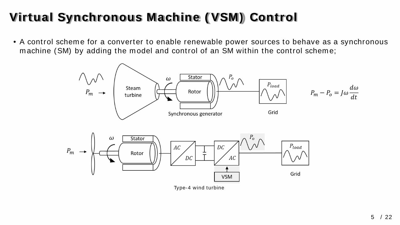
𝑃𝑃𝑚𝑚 − 𝑃𝑃𝑜𝑜 = 𝐽𝐽𝜔𝜔𝑑𝑑𝜔𝜔𝑑𝑑𝑑𝑑
Type-4 wind turbine
Power System Frequency StabilityVirtual Synchronous Machine (VSM) Control
/ 225
• A control scheme for a converter to enable renewable power sources to behave as a synchronous machine (SM) by adding the model and control of an SM within the control scheme;
𝑃𝑃𝑚𝑚
𝑃𝑃𝑚𝑚
𝜔𝜔
𝜔𝜔
𝑃𝑃𝑚𝑚 − 𝑃𝑃𝑜𝑜 = 𝐽𝐽𝜔𝜔𝑑𝑑𝜔𝜔𝑑𝑑𝑑𝑑
Type-4 wind turbine

Prabha Kundur, Neal J. Balu and Mark G. Lauby. Power system stability and control. Vol. 7. New York: McGraw-Hill, 1994.
Synchronous Generator (SG) Model and Control
/ 226
∆�̇�𝜔∆�̇�𝛿∆Ψ̇𝑓𝑓𝑓𝑓∆Ψ̇1𝑓𝑓∆Ψ̇1𝑞𝑞∆Ψ̇2𝑞𝑞
=
𝑎𝑎11𝑎𝑎21
0000
𝑎𝑎120𝑎𝑎32𝑎𝑎42𝑎𝑎52𝑎𝑎62
𝑎𝑎130𝑎𝑎33𝑎𝑎43𝑎𝑎53𝑎𝑎63
𝑎𝑎140𝑎𝑎34𝑎𝑎44𝑎𝑎54𝑎𝑎64
𝑎𝑎150𝑎𝑎35𝑎𝑎45𝑎𝑎55𝑎𝑎65
𝑎𝑎160𝑎𝑎36𝑎𝑎46𝑎𝑎56𝑎𝑎66
∆𝜔𝜔∆𝛿𝛿∆Ψ𝑓𝑓𝑓𝑓∆Ψ1𝑓𝑓∆Ψ1𝑞𝑞∆Ψ2𝑞𝑞
+
𝑏𝑏1100000
00𝑏𝑏32000
∆𝑇𝑇𝑚𝑚∆𝐸𝐸𝑓𝑓𝑓𝑓
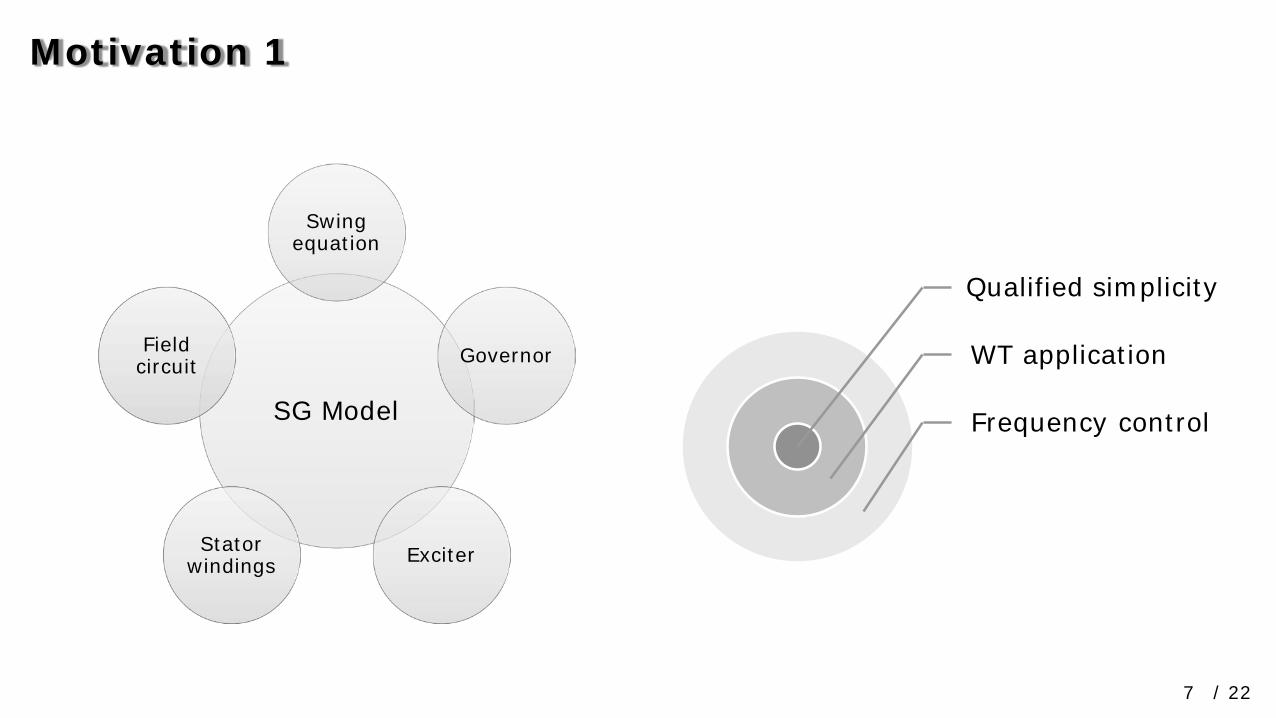
Motivation 1
/ 227
Qualified simplicity
WT application
Frequency controlSG Model
Swing equation
Governor
ExciterStator windings
Field circuit
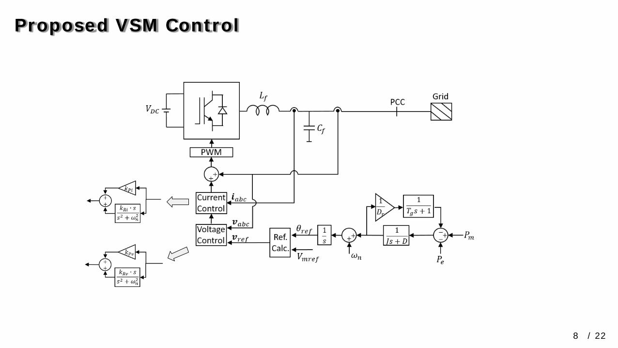
Proposed VSM Control
/ 228

Yong Chen et al. Comparison of methods for implementing virtual synchronous machine on inverters. International conference on renewable energies and power quality. 2012.
Salvatore D’Arco et al. Small-signal modeling and parametric sensitivity of a virtual synchronous machine. Power Systems Computation Conference. IEEE, 2014.
More Complex VSM Control
/ 229

Modelling & Simulation
/ 2210
25%, 50%, 75%, 100%
10 𝑘𝑘𝑘𝑘
1 𝑃𝑃,𝑄𝑄,𝑉𝑉, 𝑓𝑓
2 Simulation time
Grid-side converter
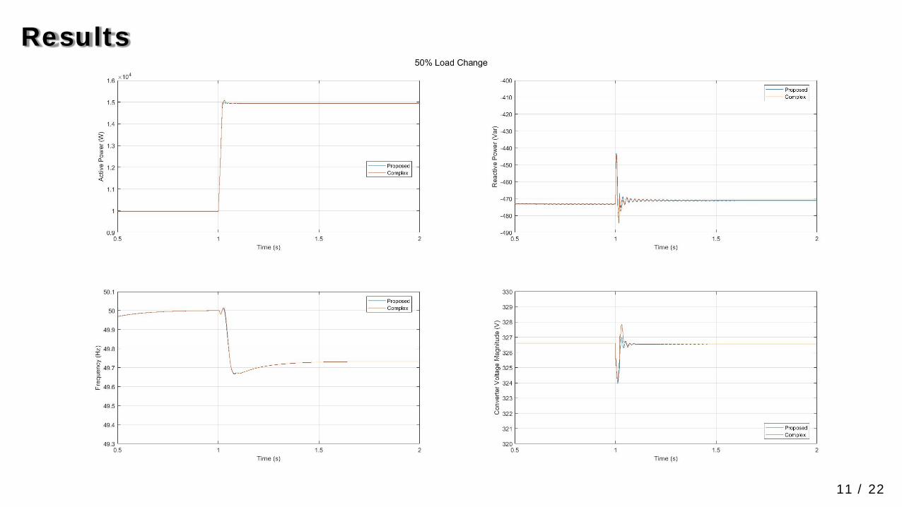
Results
/ 2211
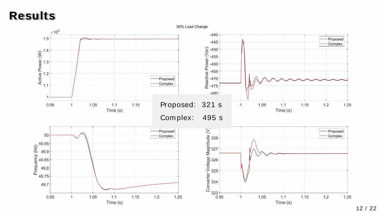
Results
/ 2212
Proposed: 321 s
Complex: 495 s

Conclusions 1
/ 2213
• A simpler but qualified VSM control scheme is proposed for frequency control;
• The proposed VSM control scheme is adapted for WT application;
• To achieve VSM control for frequency control capability of WTs, to emulate the swing equation and governor is enough;
• Including the modeling of exciter and stator windings does not improve much, while increasing dynamics of voltage;
• Including the modeling of field circuit will make things more complex, not necessary;
• The proposed VSM control scheme works better in voltage control;
Motivation 2
/ 2214https://orbit.dtu.dk/en/activities/a-virtual-synchronous-machine-control-scheme-for-wind-turbines(4cdc26fd-1829-4c00-af62-5775529c73f3).html
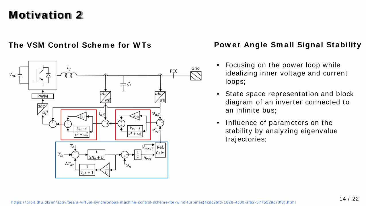
The VSM Control Scheme for WTs Power Angle Small Signal Stability
• Focusing on the power loop while idealizing inner voltage and current loops;
• State space representation and block diagram of an inverter connected to an infinite bus;
• Influence of parameters on the stability by analyzing eigenvalue trajectories;

Power Angle Small Signal Stability (PAS) Model
/ 2215
1 12 2 2 2
0 0 01 1 00
s
n m
dr dr
g r g
KDH H H Hd T
dtT T
T D T
ω ωδ ω δ
− − − ∆ ∆ ∆ = ∆ + ∆ ∆ ∆ −
0cosbs
E EKX
δ′
=

Verification
/ 2216
Grid-side converter Voltage source
• 𝑑𝑑 = 1𝑠𝑠, 𝑇𝑇𝑚𝑚 is dropped by 0.5 pu, or 𝑃𝑃𝑚𝑚is dropped by 5 𝑘𝑘𝑘𝑘
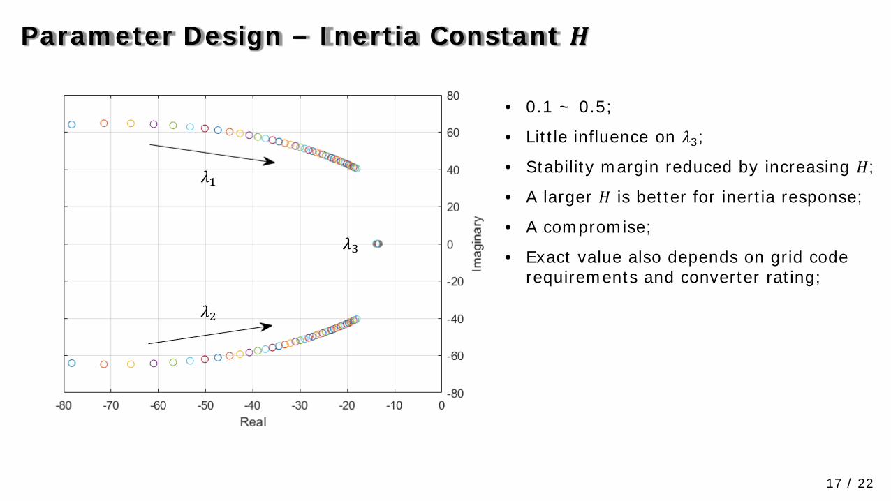
Parameter Design – Inertia Constant 𝑯𝑯
/ 2217
• 0.1 ~ 0.5;
• Little influence on 𝜆𝜆3;
• Stability margin reduced by increasing 𝐻𝐻;
• A larger 𝐻𝐻 is better for inertia response;
• A compromise;
• Exact value also depends on grid code requirements and converter rating;
𝜆𝜆1
𝜆𝜆2
𝜆𝜆3

Parameter Design – Damping Coefficient 𝑫𝑫
/ 2218
• 10~53: stable, 54~100: unstable;
• Little influence on 𝜆𝜆3;
• Stability margin improved by increasing 𝐷𝐷in the stable range;
• Positive effects of a smaller 𝐷𝐷;
• A trade-off;
𝜆𝜆1
𝜆𝜆2𝜆𝜆3
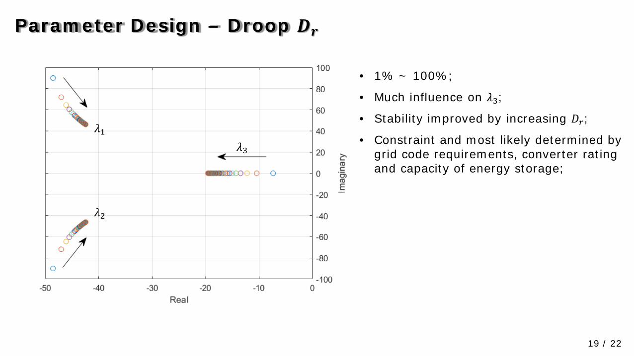
Parameter Design – Droop 𝑫𝑫𝒓𝒓
/ 2219
• 1% ~ 100%;
• Much influence on 𝜆𝜆3;
• Stability improved by increasing 𝐷𝐷𝑟𝑟;
• Constraint and most likely determined by grid code requirements, converter rating and capacity of energy storage;
𝜆𝜆1
𝜆𝜆2
𝜆𝜆3

Parameter Design – Response Time 𝑻𝑻𝒈𝒈
/ 2220
• 0.01 ~ 10;
• Much influence on 𝜆𝜆3;
• Stability is worse when increasing 𝑇𝑇𝑔𝑔;
𝜆𝜆3𝜆𝜆1
𝜆𝜆2
Conclusions 2 & Future Work
/ 2221
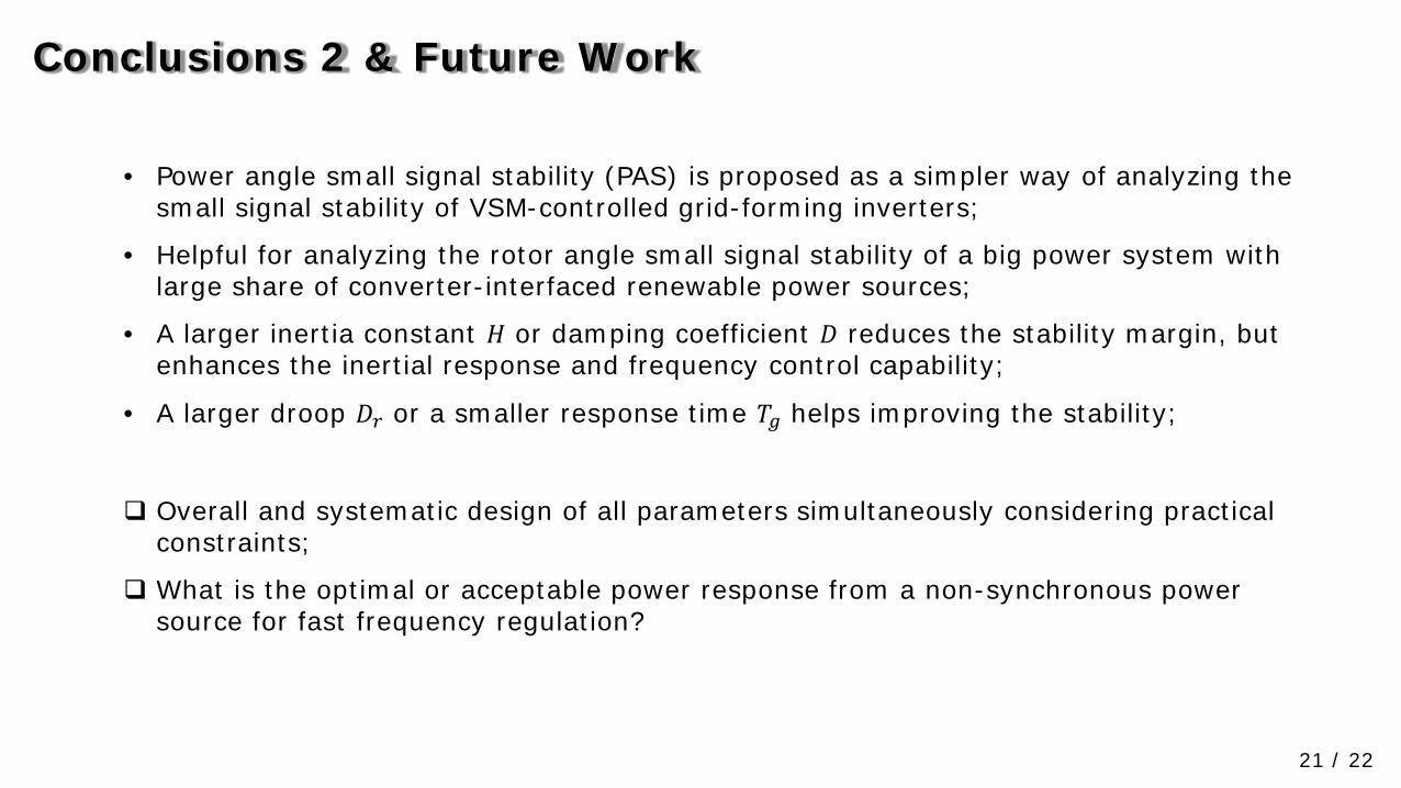
• Power angle small signal stability (PAS) is proposed as a simpler way of analyzing the small signal stability of VSM-controlled grid-forming inverters;
• Helpful for analyzing the rotor angle small signal stability of a big power system with large share of converter-interfaced renewable power sources;
• A larger inertia constant 𝐻𝐻 or damping coefficient 𝐷𝐷 reduces the stability margin, but enhances the inertial response and frequency control capability;
• A larger droop 𝐷𝐷𝑟𝑟 or a smaller response time 𝑇𝑇𝑔𝑔 helps improving the stability;
Overall and systematic design of all parameters simultaneously considering practical constraints;
What is the optimal or acceptable power response from a non-synchronous power source for fast frequency regulation?
Thank you !
Liang [email protected]
This work has received funding from the European Union’s Horizon 2020 research and innovation program under grant agreement No. 727680 (TotalControl).
This work has also received funding from project PowerKey (EUDP Project No. 12558).