Embed Size (px)
Citation preview

P a g e 1
Introduction
In this series of articles, we will be looking at each of the main stages of the electrical power system in turn. As you will recall from our Introduction to Electrical Power Systems, this can be broken down into five key areas:
Generation Transformation Transmission Distribution Protection
Each article in this series will comprise a brief overview of the topic in question, and will focus on the learning objectives within that field. We will relate these to our individual Power System Laboratory modules, and detail the range and depth of the experimental scope, highlighting important concepts along the way.
Finally, we will discuss our Power System Trainer, and detail the added experimental scope that an integrated system will cover, and how this relates to some of the key issues in the power industry.
The Distribution of Electrical Power
As discussed in the Introduction to Electrical Power Systems, once the electrical power has been transmitted through the grid system around the country, it is then stepped back down to a lower voltage as it enters the distribution network. At this stage, depending on the types of consumers and the local population, this medium voltage network will typically be in the region of a few tens of kV. These voltages are further stepped down through a network of substations, located ever closer to the end customers.
In built up areas, most of these cables will run underground, but in more rural areas, one will typically see overhead cables supported on utility poles. Close to the customers, the voltage is again stepped down by a distribution transformer to the level of the low voltage secondary circuit, most commonly either 120 V or 240 V.
P o w e r s y s t e m s 4 : D i s t r i b u t i o n
P a g e 2
Understanding the behaviour and characteristics of distribution networks is a fundamental requirement for any electrical power system engineer. The effects of different loads and power factors, as well as fault conditions, all need to be understood in order to maximise the efficiency of the electrical network, and to ensure that customers experience a reliable and stable electricity supply to their homes and workplaces.
In our PSL40, which is a laboratory-scale version of an electrical distribution system, we are able to configure different single and three phase distribution networks and loading scenarios, and examine voltage control techniques within the system. As with all the PSL range, protection systems are studied in detail.
In order to create a safe working environment for students, all parameters within the three phase network use a per-unit-value system, which means that all voltages, currents, etc are scaled down in proportion.
The PSL40 allows students to perform a range of experiments on both single-phase and three-phase distribution networks, including:
AC/DC transmission Radial and ring systems with different load types Distribution losses and efficiency Voltage control through reactive power compensation Use of a tapped distribution transformer for load voltage control Three-phase distribution system with balanced and unbalanced loads Effect of an open-circuited neutral conductor on voltage across a single-phase load Effect on line current of improved power factor Distribution system under faults Protection Relay discrimination
We shall take a brief look at the PSL40 itself, and how it fits into the overall context of our Power Systems range, before turning to these experiments in a bit more detail, and then we shall look at Distribution as part of the integrated Power System Trainer.
P a g e 3
The TecQuipment Power Systems Range
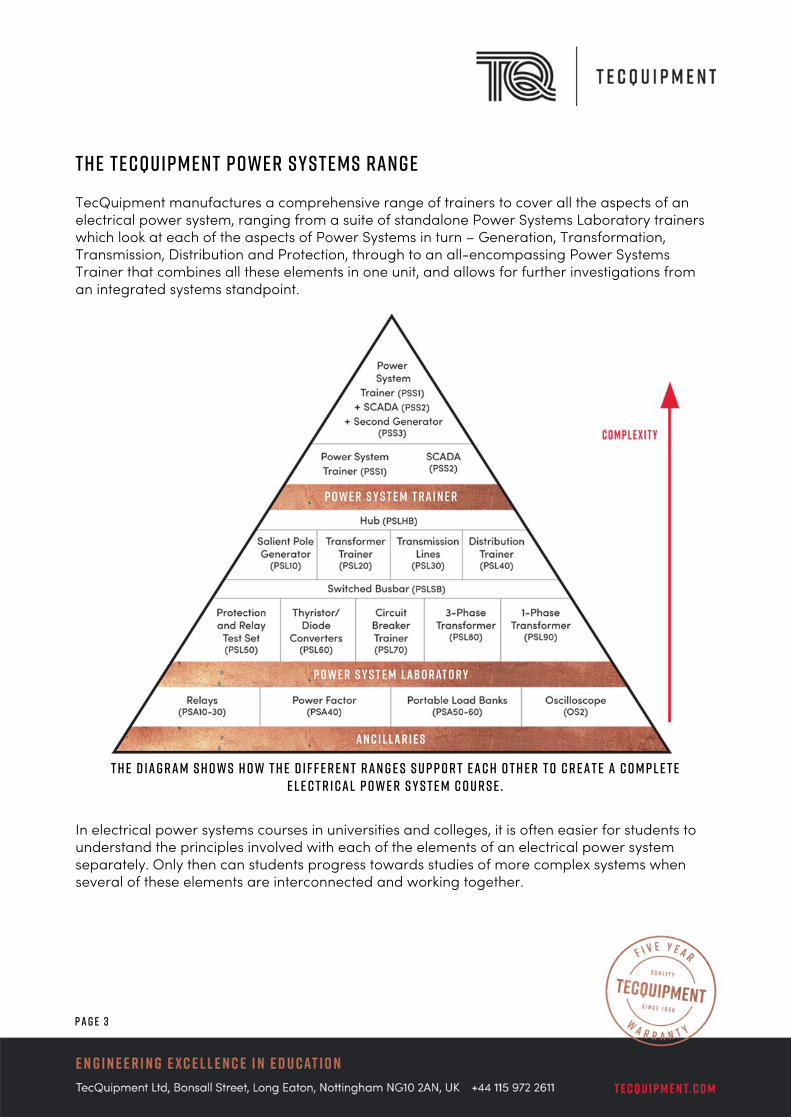
TecQuipment manufactures a comprehensive range of trainers to cover all the aspects of an electrical power system, ranging from a suite of standalone Power Systems Laboratory trainers which look at each of the aspects of Power Systems in turn – Generation, Transformation, Transmission, Distribution and Protection, through to an all-encompassing Power Systems Trainer that combines all these elements in one unit, and allows for further investigations from an integrated systems standpoint.
T h e d i a g r a m s h o w s h o w t h e d i f f e r e n t r a n g e s s u p p o r t e a c h o t h e r t o c r e a t e a c o m p l e t e
E l e c t r i c a l P o w e r S y s t e m c o u r s e . In electrical power systems courses in universities and colleges, it is often easier for students to understand the principles involved with each of the elements of an electrical power system separately. Only then can students progress towards studies of more complex systems when several of these elements are interconnected and working together.
P a g e 4
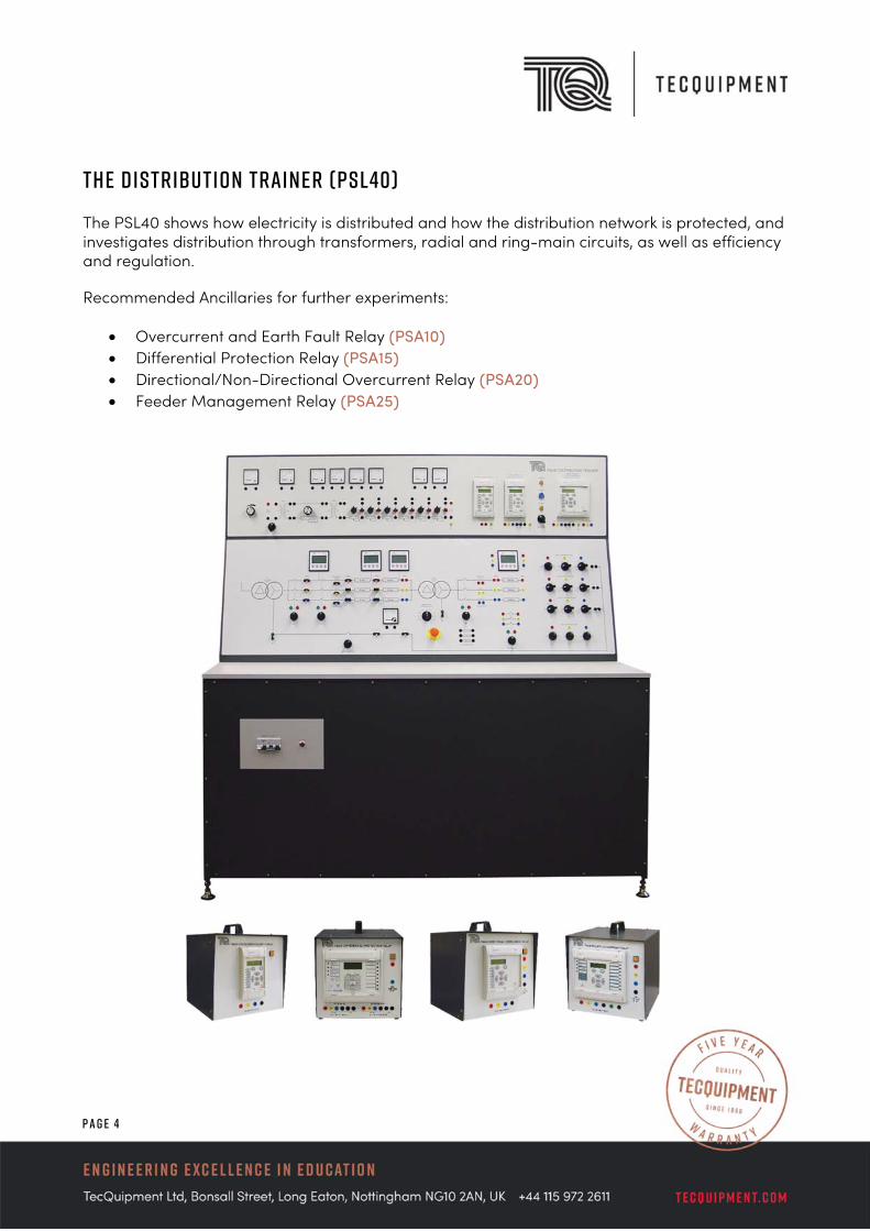
The Distribution Trainer (PSL40)
The PSL40 shows how electricity is distributed and how the distribution network is protected, and investigates distribution through transformers, radial and ring-main circuits, as well as efficiency and regulation.
Recommended Ancillaries for further experiments:
Overcurrent and Earth Fault Relay (PSA10) Differential Protection Relay (PSA15) Directional/Non-Directional Overcurrent Relay (PSA20) Feeder Management Relay (PSA25)

P a g e 5
Description of the PSL40 and Key Experiments
The PSL40 is comprised of several components, and the console is divided into two main sections:
an upper panel that shows the basics of distribution a lower panel that shows more advanced three-phase power distribution
U p p e r P a n el The upper panel includes low-voltage AC and DC supplies, a set of lamps and variable resistances. The resistances simulate a feeder cable and the lamps simulate loads. Students may connect the feeder circuit to learn the principles of ring main and radial circuits. The low-voltage AC supplies may be connected to show the principles of regulation.
L o w e r P a n e l The lower panel includes connections to two three-phase transformers (TXA and TXB), transmission lines, and load banks to simulate industrial power distribution. One transformer reduces the voltage from the incoming supply to the correct value for the experiments. This is the ‘line power’ transformer. The other transformer reduces the line voltage down to 110 V and acts as the ‘line receive’ transformer. Its primary tappings are adjustable and its secondary winding star point can be connected to earth.
Both panels include all current, voltage and power meters needed for the experiments.
Two forms of line representation are provided in the Trainer. The single-phase circuit has variable resistors; the three-phase circuit has inductors whose ohmic values are expressed in the per-unit system.
For protection tests, the circuits include current transformers to connect to the protection relays fitted to the control panels.
The student connects and sets the protection relays to detect line and earth currents. The relays also monitor and measure fault events and disturbances for fault analysis. The student sets the two simplest relays from their local control panels. The more complex relay is set from its local panel, or by a cable link to a suitable computer. When a circuit fault is applied, the relays open circuit-breakers in the test circuits. The circuit-breakers also include hand-operated switches, and lamps. The lamps show whether the circuit-breakers are open or closed.
As with all the modular PSL Trainers, there is a virtually unlimited range of experiments that can be performed. The PSL40 manual describes a structured range of these experiments that the student can perform, beginning with fundamental analysis of AC and DC transmission, where the student can investigate the advantages of using high voltage AC for the transmission of
P a g e 6
electrical power. Long high voltage lines can be modelled using the variable resistance between TXA and TXB, and the effects of this can be directly compared with low voltage DC lines.
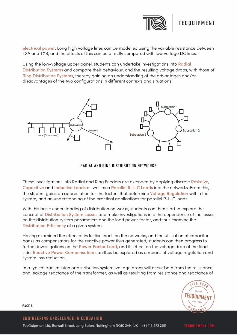
Using the low-voltage upper panel, students can undertake investigations into Radial Distribution Systems and compare their behaviour, and the resulting voltage drops, with those of Ring Distribution Systems, thereby gaining an understanding of the advantages and/or disadvantages of the two configurations in different contexts and situations.
R a d i a l a n d R i n g D i s t r i b u t i o n N e t w o r k s
These investigations into Radial and Ring Feeders are extended by applying discrete Resistive, Capacitive and Inductive Loads as well as a Parallel R-L-C Loads into the networks. From this, the student gains an appreciation for the factors that determine Voltage Regulation within the system, and an understanding of the practical applications for parallel R-L-C loads.
With this basic understanding of distribution networks, students can then start to explore the concept of Distribution System Losses and make investigations into the dependence of the losses on the distribution system parameters and the load power factor, and thus examine the Distribution Efficiency of a given system.
Having examined the effect of inductive loads on the networks, and the utilisation of capacitor banks as compensators for the reactive power thus generated, students can then progress to further investigations on the Power Factor Load, and its effect on the voltage drop at the load side. Reactive Power Compensation can thus be explored as a means of voltage regulation and system loss reduction.
In a typical transmission or distribution system, voltage drops will occur both from the resistance and leakage reactance of the transformer, as well as resulting from resistance and reactance of

P a g e 7
the lines between the transformer and the load. To counter this, voltage-regulating equipment is installed in distribution networks. The PSL40 models this by incorporating an Off-Load Tap Changer on the primary side of the 220/110 V delta-star transformer. Thus the student is able to analyse Load Voltage Control using a Tapped Distribution Transformer.
P h a s o r D i a g r a m f o r a L a g g i n g P o w e r F a c t o r L o a d
Balanced and Unbalanced Resistive and Inductive Loads are investigated for a Three-phase, Four-wire Distribution System, and the effect of these on the phase current and the phase angle is analysed. In addition, the effect of balanced/unbalanced loads on an Open-Circuited Neutral Conductor across Single-phase Loads can be observed, highlighting some of the important safety considerations that electrical engineers need to understand and take into account when designing distribution systems. Symmetrical Component Analysis is used to examine and resolve unbalanced three-phase loads.
P r o t e c t i o n R e l a y s One of the most important safety measures built in to electrical power systems is the use of protection relays for different types of faults. Built in to the PSL40 is a single-phase Overcurrent relay, a three-phase Overcurrent relay, and a Directional three-phase Overcurrent relay, allowing experiments in:
Distribution System Protection Distribution System Under Faults
P a g e 8
Protection Relay Discrimination Faults on an Unloaded System Faults on a Loaded System
These relays can be complemented by a range of additional, optional relays that can be studied with the PSL40. This allows for a flexible range of additional experiments to be designed and performed:
Overcurrent and Earth Fault Relay (PSA10) Differential Protection Relay (PSA15) Directional/Non-Directional Overcurrent Relay (PSA20) Feeder Management Relay (PSA25)
S u m m a r y o f P S L 4 0 L e a r n i n g O b j e c t i v e s
Thus, using the PSL40 Distribution Trainer, students progress incrementally from understanding the fundamental principles and characteristics of distribution networks, to their operation and performance in more complex systems, developing an appreciation for the various techniques involved in providing a reliable and efficient electrical supply in the real world.
Further Studies in Distribution For further, more detailed study of Distribution within the context of an integrated Electrical Power System, the PSS1 Power Systems Trainer takes the student to the next level. Whilst there is some overlap between the PSL40 and the PSS1 in terms of the experiments that can be performed, the PSS1 is focused much more on the role and interaction of distribution within the wider context of a real world system. Some of the experiments that the student performs with the PSL40, such as the more fundamental characteristics of AC and DC lines, and general properties of Radial networks, for example, are not covered by the PSS1. Instead, it is assumed that the student has already covered these topics and developed a mastery of the fundamental principles of Distribution with the PSL40.
The next section, therefore, looks at the capabilities of the PSS1 and the scope of experimentation that it offers in the context of Distribution, including the additional experiments that can be performed with the inclusion of the PSS3 Second Generator.
P a g e 9
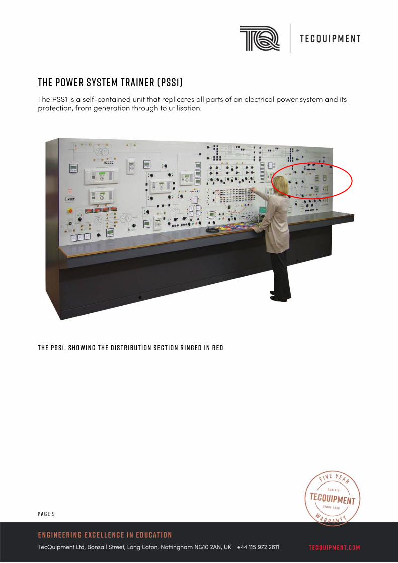
The Power System Trainer (PSS1) The PSS1 is a self-contained unit that replicates all parts of an electrical power system and its protection, from generation through to utilisation.
T h e P S S 1 , s h o w i n g t h e D i s t r i b u t i o n s e c t i o n r i n g e d i n r e d
P a g e 1 0
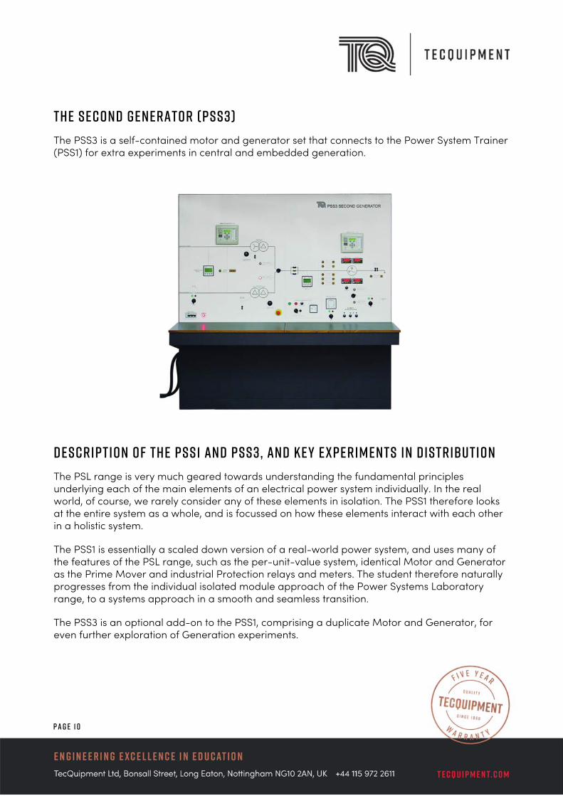
The Second Generator (PSS3) The PSS3 is a self-contained motor and generator set that connects to the Power System Trainer (PSS1) for extra experiments in central and embedded generation.
Description of the PSS1 and PSS3, and Key Experiments in Distribution The PSL range is very much geared towards understanding the fundamental principles underlying each of the main elements of an electrical power system individually. In the real world, of course, we rarely consider any of these elements in isolation. The PSS1 therefore looks at the entire system as a whole, and is focussed on how these elements interact with each other in a holistic system.
The PSS1 is essentially a scaled down version of a real-world power system, and uses many of the features of the PSL range, such as the per-unit-value system, identical Motor and Generator as the Prime Mover and industrial Protection relays and meters. The student therefore naturally progresses from the individual isolated module approach of the Power Systems Laboratory range, to a systems approach in a smooth and seamless transition.
The PSS3 is an optional add-on to the PSS1, comprising a duplicate Motor and Generator, for even further exploration of Generation experiments.

P a g e 1 1
The construction and layout of the PSS1 makes it an extremely versatile trainer, allowing the student virtually unlimited flexibility and experimental scope. As a result, the PSS1 is ideally suited for advanced project work and is a perfect system to perform scenario-based learning within either an academic environment, or in a more industrially-focussed technical training environment.
T h e D i s t r i b u t i o n a n d U t i l i s a t i o n B u s o f t h e P S S 1 Experimental topics that are particularly relevant from a Distribution context include Directional Control of Relay Tripping, particularly in its application to Parallel Feeders and Parallel Transformers.
P a g e 1 2
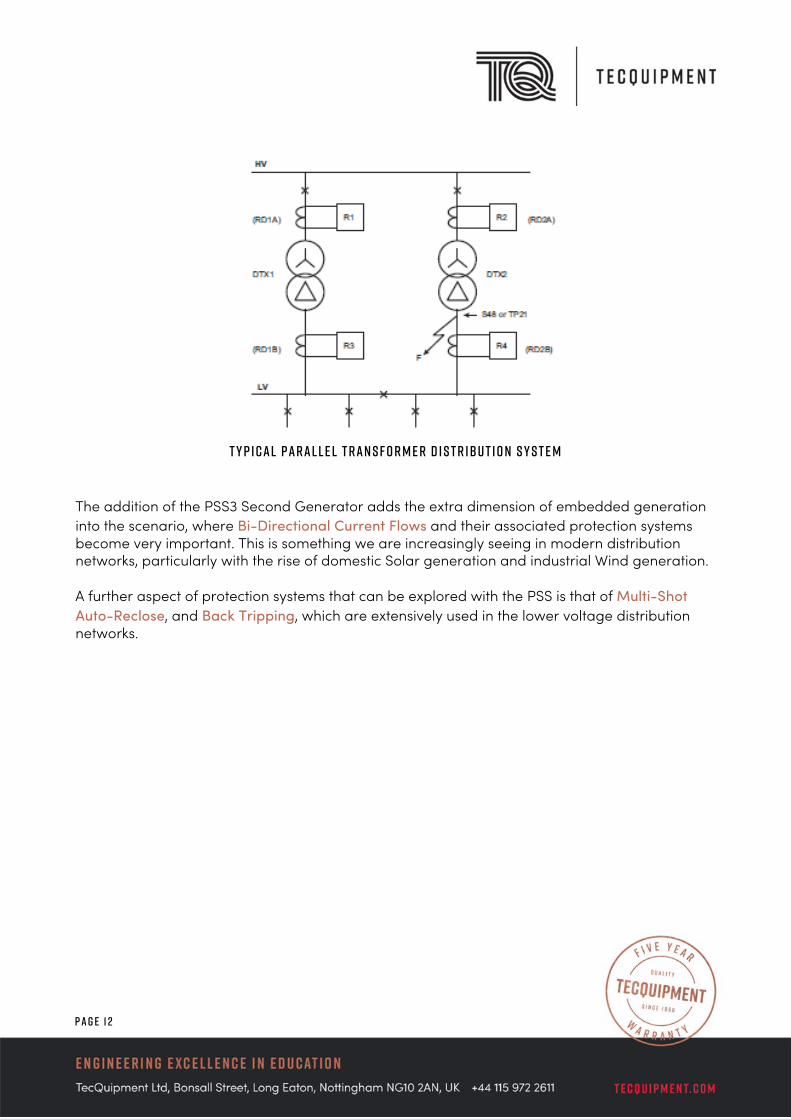
T y p i c a l P a r a l l e l T r a n s f o r m e r D i s t r i b u t i o n S y s t e m
The addition of the PSS3 Second Generator adds the extra dimension of embedded generation into the scenario, where Bi-Directional Current Flows and their associated protection systems become very important. This is something we are increasingly seeing in modern distribution networks, particularly with the rise of domestic Solar generation and industrial Wind generation.
A further aspect of protection systems that can be explored with the PSS is that of Multi-Shot Auto-Reclose, and Back Tripping, which are extensively used in the lower voltage distribution networks.
P a g e 1 3
S u m m a r y
The above experiments are only a sample of the capability of the Power Systems Trainer in the context of Distribution. The flexible design of the PSS1 and PSS3 allows for a much wider range of experiments to be designed and performed, and thus it is ideally suited for further project work and research activities. As it covers all the key elements of a power system, from Generation to Utilisation, it has become a very powerful tool to be used in Scenario Based Learning, in both an academic environment as well as in an industrial/technical training context. Many customers around the world have benefitted greatly from the TecQuipment Power Systems range, whether it is to teach students the fundamental principles of electrical power, or to train the next generation of electrical power system engineers serving the needs of industry.
For further details of the TecQuipment Power Systems range, and to see how it could be of value to your institution, please feel free to contact our Sales Team who will be more than happy to discuss your specific requirements.