Embed Size (px)
Citation preview

Power Systems
Beginning troubleshooting and problem analysis
���


Power Systems
Beginning troubleshooting and problem analysis
���

NoteBefore using this information and the product it supports, read the information in “Notices,” onpage 175, the IBM Systems Safety Notices manual, G229-9054, and the IBM Environmental Notices andUser Guide, Z125–5823.
This edition applies to IBM® Power Systems™ servers that contain the POWER6™ processor and to all associatedmodels.
© Copyright International Business Machines Corporation 2007, 2009.US Government Users Restricted Rights – Use, duplication or disclosure restricted by GSA ADP Schedule Contractwith IBM Corp.

Contents
Safety notices . . . . . . . . . . . . . . . . . . . . . . . . . . . . . . . . . v
Beginning troubleshooting and problem analysis . . . . . . . . . . . . . . . . . . 1Beginning problem analysis . . . . . . . . . . . . . . . . . . . . . . . . . . . . . . 1
AIX and Linux problem analysis. . . . . . . . . . . . . . . . . . . . . . . . . . . . 7IBM i problem analysis . . . . . . . . . . . . . . . . . . . . . . . . . . . . . . . 9Problem analysis for 7874-024, 7874-040, 7874-120, and 7874-240 switches . . . . . . . . . . . . . . 13
Isolating InfiniBand switch link errors for 7874-024, 7874-040, 7874-120, and 7874-240 switches . . . . . 18Collecting data for InfiniBand switch errors for 7874-024, 7874-040, 7874-120, and 7874-240 switches . . . . 19
Collecting data from the cluster systems management server for 7874-024, 7874-040, 7874-120, and7874-240 switches . . . . . . . . . . . . . . . . . . . . . . . . . . . . . . 22Collecting data from the fabric management server for 7874-024, 7874-040, 7874-120, and 7874-240switches . . . . . . . . . . . . . . . . . . . . . . . . . . . . . . . . . 23Collecting data for Fast Fabric Health Check for 7874-024, 7874-040, 7874-120, and 7874-240 switches . . 23Capturing switch CLI output using script command for 7874-024, 7874-040, 7874-120, and 7874-240switches . . . . . . . . . . . . . . . . . . . . . . . . . . . . . . . . . 24
Problem reporting form . . . . . . . . . . . . . . . . . . . . . . . . . . . . . . 24Starting a repair action . . . . . . . . . . . . . . . . . . . . . . . . . . . . . . . 26Reference information for problem determination. . . . . . . . . . . . . . . . . . . . . . . 27
Symptom index . . . . . . . . . . . . . . . . . . . . . . . . . . . . . . . . . 28IBM i server or IBM i partition symptoms . . . . . . . . . . . . . . . . . . . . . . . 28AIX server or AIX partition symptoms . . . . . . . . . . . . . . . . . . . . . . . . 31
MAP 0410: Repair checkout . . . . . . . . . . . . . . . . . . . . . . . . . . . 41Linux server or Linux partition symptoms . . . . . . . . . . . . . . . . . . . . . . . 44
Linux fast-path problem isolation . . . . . . . . . . . . . . . . . . . . . . . . . 52Detecting problems . . . . . . . . . . . . . . . . . . . . . . . . . . . . . . . . 65
IBM i Problem determination procedures . . . . . . . . . . . . . . . . . . . . . . . 65Searching the service action log. . . . . . . . . . . . . . . . . . . . . . . . . . 65Using the product activity log . . . . . . . . . . . . . . . . . . . . . . . . . . 67Using the problem log. . . . . . . . . . . . . . . . . . . . . . . . . . . . . 67
Problem determination procedure for AIX or Linux servers or partitions . . . . . . . . . . . . . 68System unit problem determination . . . . . . . . . . . . . . . . . . . . . . . . . 68HMC machine code problems . . . . . . . . . . . . . . . . . . . . . . . . . . . 71
Launching an xterm shell . . . . . . . . . . . . . . . . . . . . . . . . . . . . 71Viewing the HMC console logs . . . . . . . . . . . . . . . . . . . . . . . . . . 72
Problem determination procedures . . . . . . . . . . . . . . . . . . . . . . . . . 73Disk drive module power-on self-tests . . . . . . . . . . . . . . . . . . . . . . . 73SCSI card power-on self-tests . . . . . . . . . . . . . . . . . . . . . . . . . . 737031-D24 or 7031-T24 Disk-drive enclosure LEDs . . . . . . . . . . . . . . . . . . . . 747031-D24 or 7031-T24 Maintenance analysis procedures. . . . . . . . . . . . . . . . . . 77
Analyzing problems . . . . . . . . . . . . . . . . . . . . . . . . . . . . . . . 87Problems with loading and starting the operating system (AIX and Linux) . . . . . . . . . . . . 88PFW1540: Problem isolation procedures . . . . . . . . . . . . . . . . . . . . . . . . 91PFW1542: I/O problem isolation procedure. . . . . . . . . . . . . . . . . . . . . . . 92PFW1543: Model 590 and model 595 MCM problem isolation procedure . . . . . . . . . . . . 107PFW1546: Model 590 and model 595 memory problem isolation procedure . . . . . . . . . . . . 109PFW1548: Memory and processor subsystem problem isolation procedure . . . . . . . . . . . . 115
PFW1548: Memory and processor subsystem problem isolation procedure when an HMC is attached 129PFW1548: Memory and processor subsystem problem isolation procedure without an HMC attached 136
Problems with noncritical resources . . . . . . . . . . . . . . . . . . . . . . . . . 144Intermittent problems . . . . . . . . . . . . . . . . . . . . . . . . . . . . . 144
About intermittent problems . . . . . . . . . . . . . . . . . . . . . . . . . . 145General intermittent problem checklist . . . . . . . . . . . . . . . . . . . . . . . 146Analyzing intermittent problems . . . . . . . . . . . . . . . . . . . . . . . . . 148Intermittent symptoms . . . . . . . . . . . . . . . . . . . . . . . . . . . . 148
© Copyright IBM Corp. 2007, 2009 iii

Failing area intermittent isolation procedures . . . . . . . . . . . . . . . . . . . . . 148IPL problems . . . . . . . . . . . . . . . . . . . . . . . . . . . . . . . . 149
Cannot perform IPL from the control panel (no SRC) . . . . . . . . . . . . . . . . . . 149Cannot perform IPL at a specified time (no SRC) . . . . . . . . . . . . . . . . . . . 150Cannot automatically perform an IPL after a power failure . . . . . . . . . . . . . . . . 153
Power problems . . . . . . . . . . . . . . . . . . . . . . . . . . . . . . . 154Cannot power on system unit . . . . . . . . . . . . . . . . . . . . . . . . . . 154Cannot power on SPCN-controlled I/O expansion unit . . . . . . . . . . . . . . . . . 158Cannot power off system or SPCN-controlled I/O expansion unit . . . . . . . . . . . . . . 164
Appendix. Notices . . . . . . . . . . . . . . . . . . . . . . . . . . . . . . 175Trademarks . . . . . . . . . . . . . . . . . . . . . . . . . . . . . . . . . . . 176Electronic emission notices . . . . . . . . . . . . . . . . . . . . . . . . . . . . . . 176
Class A Notices. . . . . . . . . . . . . . . . . . . . . . . . . . . . . . . . . 176Terms and conditions. . . . . . . . . . . . . . . . . . . . . . . . . . . . . . . . 180
iv

Safety notices
Safety notices may be printed throughout this guide:v DANGER notices call attention to a situation that is potentially lethal or extremely hazardous to
people.v CAUTION notices call attention to a situation that is potentially hazardous to people because of some
existing condition.v Attention notices call attention to the possibility of damage to a program, device, system, or data.
World Trade safety information
Several countries require the safety information contained in product publications to be presented in theirnational languages. If this requirement applies to your country, a safety information booklet is includedin the publications package shipped with the product. The booklet contains the safety information inyour national language with references to the U.S. English source. Before using a U.S. English publicationto install, operate, or service this product, you must first become familiar with the related safetyinformation in the booklet. You should also refer to the booklet any time you do not clearly understandany safety information in the U.S. English publications.
German safety information
Das Produkt ist nicht für den Einsatz an Bildschirmarbeitsplätzen im Sinne § 2 derBildschirmarbeitsverordnung geeignet.
Laser safety information
IBM® servers can use I/O cards or features that are fiber-optic based and that utilize lasers or LEDs.
Laser compliance
All lasers are certified in the U.S. to conform to the requirements of DHHS 21 CFR Subchapter J for class1 laser products. Outside the U.S., they are certified to be in compliance with IEC 60825 as a class 1 laserproduct. Consult the label on each part for laser certification numbers and approval information.
CAUTION:This product might contain one or more of the following devices: CD-ROM drive, DVD-ROM drive,DVD-RAM drive, or laser module, which are Class 1 laser products. Note the following information:
v Do not remove the covers. Removing the covers of the laser product could result in exposure tohazardous laser radiation. There are no serviceable parts inside the device.
v Use of the controls or adjustments or performance of procedures other than those specified hereinmight result in hazardous radiation exposure.
(C026)
CAUTION:Data processing environments can contain equipment transmitting on system links with laser modulesthat operate at greater than Class 1 power levels. For this reason, never look into the end of an opticalfiber cable or open receptacle. (C027)
CAUTION:This product contains a Class 1M laser. Do not view directly with optical instruments. (C028)
© Copyright IBM Corp. 2007, 2009 v

CAUTION:Some laser products contain an embedded Class 3A or Class 3B laser diode. Note the followinginformation: laser radiation when open. Do not stare into the beam, do not view directly with opticalinstruments, and avoid direct exposure to the beam. (C030)
Power and cabling information for NEBS (Network Equipment-Building System)GR-1089-CORE
The following comments apply to the IBM servers that have been designated as conforming to NEBS(Network Equipment-Building System) GR-1089-CORE:
The equipment is suitable for installation in the following:v Network telecommunications facilitiesv Locations where the NEC (National Electrical Code) applies
The intrabuilding ports of this equipment are suitable for connection to intrabuilding or unexposedwiring or cabling only. The intrabuilding ports of this equipment must not be metallically connected to theinterfaces that connect to the OSP (outside plant) or its wiring. These interfaces are designed for use asintrabuilding interfaces only (Type 2 or Type 4 ports as described in GR-1089-CORE) and require isolationfrom the exposed OSP cabling. The addition of primary protectors is not sufficient protection to connectthese interfaces metallically to OSP wiring.
Note: All Ethernet cables must be shielded and grounded at both ends.
The ac-powered system does not require the use of an external surge protection device (SPD).
The dc-powered system employs an isolated DC return (DC-I) design. The DC battery return terminalshall not be connected to the chassis or frame ground.
vi

Beginning troubleshooting and problem analysis
This information provides a starting point for analyzing problems.
This information is the starting point for diagnosing and repairing servers. From this point, you areguided to the appropriate information to help you diagnose server problems, determine the appropriaterepair action, and then perform the necessary steps to repair the server. A system attention light, anenclosure fault light, or a system information light indicates there is a serviceable event (an SRC in thecontrol panel or in one of the serviceable event views) on the system. This information guides youthrough finding the serviceable event.
Beginning problem analysisYou can use problem analysis to gather information that helps you determine the nature of a problemencountered on your system. This information is used to determine if you can resolve the problemyourself or to gather sufficient information to communicate with a service provider and quicklydetermine the service action that needs to be taken.
The method of finding and collecting error information depends on the state of the hardware at the timeof the failure. This procedure directs you to one of the following places to find error information:v The Hardware Management Console (HMC) error logsv The operating system’s error logv The control panelv The Integrated Virtualization Managerv The Advanced System Management Interface (ASMI) error logs
If you are using this information because of a problem with your HMC, see Managing the HMC.
To begin analyzing the problem, complete the following steps:1. Are all processor enclosures and I/O enclosures powered on or are you able to power them on?
Note: An enclosure is powered on when its green power indicator is on and not blinking.
v Yes: Go to step 3 on page 2.
v No: Continue with the next step.
2. Ensure that the power supplied to the system is adequate. If your processor enclosures and I/Oenclosures are protected by an emergency power off (EPO) circuit, check that the EPO switch is notactivated. Verify that all power cables are correctly connected to the electrical outlet. When power isavailable, the Function/Data display on the control panel is lit. If you have an uninterruptible powersupply, verify that the cables are correctly connected to the system, and that it is functioning. Poweron all processor and I/O enclosures.
© Copyright IBM Corp. 2007, 2009 1

Did all enclosures power on? Note: An enclosure is powered on when itsgreen power indicator is on and not blinking.
In a single-enclosure server with a redundantservice processor, a progress code displays onthe control (operator) panel several secondsafter ac power is first applied. This progresscode remains on the control panel for 1-2minutes, then the progress code is updatedevery 20-30 seconds as the system powers on.
In a multiple-enclosure server with aredundant service processor, a progress codedoes not display on the control (operator)panel until 1-2 minutes after ac power is firstapplied. After the first progress code displays,the progress code is updated every 20-30seconds as the server powers on.
v Yes: This ends the procedure.
v No: Continue with the next step.
3. Is the failing hardware managed by an HMC?
v Yes: Go to step 12 on page 4.
v No: Continue with the next step.
4. Is your system being managed by the Integrated Virtualization Manager?
v Yes: Go to step 16 on page 5.
v No: Continue with the next step. Refer to the appropriate procedure:
– If you are having a problem with an AIX® or Linux® server, go to “AIX and Linux problem analysis” on page 7.
– If you are having a problem with an IBM i server, go to “IBM i problem analysis” on page 9.
– If you are having a problem with an InfiniBand switch, go to “Problem analysis for 7874-024, 7874-040, 7874-120,and 7874-240 switches” on page 13.
5. If an operating system was running at the time of the failure, information about the failure is foundin the operating system’s serviceable event view unless the failure prevented the operating systemfrom doing so. If that operating system is no longer running, attempt to reboot it before answeringthe following question.
Was an operating system running at the time of the failure and is the operating system running now?
v Yes: Go to step 11 on page 3.
v No: Continue with the next step.
6. Details about errors that occur when an operating system is not running or is now not accessible canbe found in the control panel or in the Advanced System Management Interface (ASMI).
Do you choose to look for error details using ASMI?
v Yes: Go to step 19 on page 6.
v No: Continue with the next step.
2

7. At the control panel, complete the following steps.
1. Press the increment or decrement button until the number 11 isdisplayed in the upper-left corner of the display.
2. Press Enter to display the contents of function 11.
3. Look in the upper-right corner for a reference code.
Is there a reference code displayed on the control panel in function11?
v Yes: Continue with the next step.
v No: Contact your hardware service provider.
8. The reference code description might provide information or an action that you can take to correctthe failure.
Go to the Reference code finder and type the reference code in the field provided. Read the reference codedescription and return here. Do not take any other action at this time.
Was there a reference code description that enabled you to resolve the problem?
v Yes: This ends the procedure.
v No: Continue with the next step.
9. Service is required to resolve the error. Collect as much error data as possible and record it. You andyour service provider will develop a corrective action to resolve the problem based on the followingguidelines:
v If a field-replaceable unit (FRU) location code is provided in the serviceable event view or control panel, thatlocation should be used to determine which FRU to replace.
v If an isolation procedure is listed for the reference code in the reference code lookup information, include it as acorrective action even if it is not listed in the serviceable event view or control panel.
v If any FRUs are marked for block replacement, replace all FRUs in the block replacement group at the same time.
To find error details:
1. Press Enter to display the contents of function 14. If data is available in function 14, the reference code has a FRUlist.
2. Record the information in functions 11 through 20 on the control panel.
3. Contact your service provider and report the reference code and other information.
This ends the procedure.
10. Is your system being managed by the Integrated Virtualization Manager?
Note: If you install the Virtual I/O Server on a non-HMC managed server, the IntegratedVirtualization Manager is enabled.
v Yes: Go to step 16 on page 5.
v No: Continue with the next step.
11. If you are having a problem with an AIX or Linux, IBM i server, or InfiniBand switch, go to theappropriate procedure.
Beginning troubleshooting and problem analysis 3

v If you are having a problem with an AIX or Linux server, go to “AIX and Linux problem analysis”on page 7.
v If you are having a problem with an IBM i server, go to “IBM i problem analysis” on page 9.v If you are having a problem with an InfiniBand switch, go to “Problem analysis for 7874-024,
7874-040, 7874-120, and 7874-240 switches” on page 13.
This ends the procedure.
12. Is the HMC functional and connected to the hardware?
v Yes: Continue with the next step.
v No: Start the HMC and attach it to the server. Then return here and continue with the next step.
13. On HMC that is used to manage the server, complete the following step:
1. In the Navigation Area, click Service Management → ManageEvents. The Manage Serviceable Events - Select ServiceableEvents window is shown.
2. In the Event Criteria area, for Serviceable Event Status, selectOpen. For all other criteria, select ALL, then click OK.
Scroll through the log and verify that there is a problem with thestatus of Open to correspond with the failure.
Do you find a serviceable event, or an open problem near the time ofthe failure?
Note: If you are unable to locate the reportedproblem, and there is more than one openproblem near the time of the reported failure,use the earliest problem in the log.
v Yes: Continue with the next step.
v No: Contact your hardware service provider. If you believe that there might be a problem with the InfiniBandswitch, go to “Problem analysis for 7874-024, 7874-040, 7874-120, and 7874-240 switches” on page 13.
14. The reference code description might provide information or an action that you can take to correctthe failure.
Go to the Reference code finder and type the reference code in the field provided. Read the reference codedescription and return here. Do not take any other action at this time.
Was there a reference code description that enabled you to resolve the problem?
v Yes: This ends the procedure.
v No: Continue with the next step.
15. Service is required to resolve the error. Collect as much error data as possible and record it. You andyour service provider will develop a corrective action to resolve the problem based on the followingguidelines:
4

v If a FRU location code is provided in the serviceable event view or control panel, that location should be used todetermine which FRU to replace.
v If an isolation procedure is listed for the reference code in the reference code lookup information, include it as acorrective action even if it is not listed in the serviceable event view or control panel.
v If any FRUs are marked for block replacement, replace all FRUs in the block replacement group at the same time.
From the Repair Serviceable Event window, complete the following steps:
1. Record the problem management record (PMR) number for the problem if one is listed.
2. Select the serviceable event from the list.
3. Select Selected and View Details.
4. Record the reference code and FRU list found in the Serviceable Event Details.
5. If a PMH number was found for the problem on the Serviceable Event Overview panel, the problem has alreadybeen reported. If there was no PMH number for the problem, contact your service provider.
This ends the procedure.
16. Logon to the Integrated Virtualization Manager interface if not already logged on.
v In the Integrated Virtualization Manager Navigation bar, select Manage Serviceable Events (under ServiceManagement).
v Scroll through the log and verify that there is a problem with the status of Open to correspond with the failure.
Do you find a serviceable event, or an open problem near the time of the failure?
v Yes: Continue with the next step.
v No: Go to step 11 on page 3.
17. The reference code description might provide information or an action that you can take to correctthe failure.
Go to the Reference code finder and type the reference code in the field provided. Read the reference codedescription and return here. Do not take any other action at this time.
Was there a reference code description that enabled you to resolve the problem?
v Yes: This ends the procedure.
v No: Continue with the next step.
18. Service is required to resolve the error. Collect as much error data as possible and record it. You andyour service provider will develop a corrective action to resolve the problem based on the followingguidelines:
Beginning troubleshooting and problem analysis 5
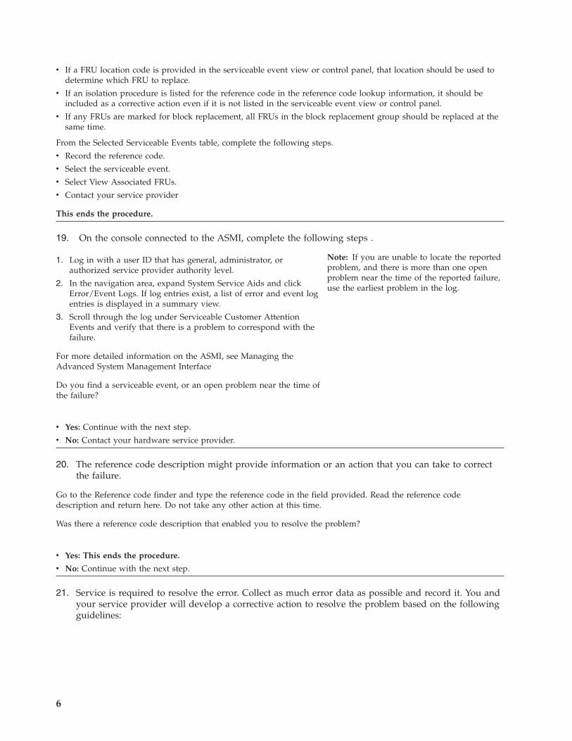
v If a FRU location code is provided in the serviceable event view or control panel, that location should be used todetermine which FRU to replace.
v If an isolation procedure is listed for the reference code in the reference code lookup information, it should beincluded as a corrective action even if it is not listed in the serviceable event view or control panel.
v If any FRUs are marked for block replacement, all FRUs in the block replacement group should be replaced at thesame time.
From the Selected Serviceable Events table, complete the following steps.
v Record the reference code.
v Select the serviceable event.
v Select View Associated FRUs.
v Contact your service provider
This ends the procedure.
19. On the console connected to the ASMI, complete the following steps .
1. Log in with a user ID that has general, administrator, orauthorized service provider authority level.
2. In the navigation area, expand System Service Aids and clickError/Event Logs. If log entries exist, a list of error and event logentries is displayed in a summary view.
3. Scroll through the log under Serviceable Customer AttentionEvents and verify that there is a problem to correspond with thefailure.
For more detailed information on the ASMI, see Managing theAdvanced System Management Interface
Do you find a serviceable event, or an open problem near the time ofthe failure?
Note: If you are unable to locate the reportedproblem, and there is more than one openproblem near the time of the reported failure,use the earliest problem in the log.
v Yes: Continue with the next step.
v No: Contact your hardware service provider.
20. The reference code description might provide information or an action that you can take to correctthe failure.
Go to the Reference code finder and type the reference code in the field provided. Read the reference codedescription and return here. Do not take any other action at this time.
Was there a reference code description that enabled you to resolve the problem?
v Yes: This ends the procedure.
v No: Continue with the next step.
21. Service is required to resolve the error. Collect as much error data as possible and record it. You andyour service provider will develop a corrective action to resolve the problem based on the followingguidelines:
6

v If a FRU location code is provided in the serviceable event view or control panel, that location should be used todetermine which FRU to replace.
v If an isolation procedure is listed for the reference code in the reference code lookup information, include it as acorrective action even if it is not listed in the serviceable event view or control panel.
v If any FRUs are marked for block replacement, replace all FRUs in the block replacement group at the same time.
From the Error Event Log view, complete the following steps:
1. Record the reference code.
2. Select the corresponding check box on the log and click Show details.
3. Record the error details.
4. Contact your service provider.
This ends the procedure.
AIX and Linux problem analysisYou can use this procedure to find information about a problem with your server hardware that isrunning the AIX or Linux
®
operating system.1. Is the operating system operational?
v Yes: Continue with the next step.
v No: Go to step 4 of the Beginning problem analysis topic to diagnose the problem.
2. Are any messages (for example, a device is not available or reporting errors) related to this problemdisplayed on the system console or sent to you in e-mail that provides a reference code?
Note: A reference code can be an 8 character system reference code (SRC) or an service requestnumber (SRN) of 5, 6, or 7 characters, with or without a hyphen.
v Yes: Continue with the next step.
v No: Go to step 4.
3. The reference code description might provide information or an action that you can take to correctthe failure.
Go to the Reference code finder and type the reference code in the field provided. Read the reference codedescription and return here. Do not take any other action at this time.
Was there a reference code description that enabled you to resolve the problem?
v Yes: This ends the procedure.
v No: Continue with the next step.
4. Are you running Linux?
v Yes: Continue with the next step.
v No: Go to step 6 on page 8.
5. To locate the error information in a system or logical partition running the Linux operating system,complete these steps:
Beginning troubleshooting and problem analysis 7

1. Log in as root user.
2. At the command line, type grep diagela /var/log/platform and press Enter.
3. Look for the most recent entry that contains a reference code.
Continue with step 8.
6. To locate the error information in a system or logical partition running AIX, complete these steps:
1. Log in to the AIX operating system as root user, or use CE login. If you need help, contact the systemadministrator.
2. Type diag to load the diagnostic controller, and display the online diagnostic menus.
3. From the Function selection menu, select Task selection.
4. From the Task selection list menu, select Display previous diagnostic results.
5. From the Previous diagnostic results menu, select Display diagnostic log summary.
Continue with the next step.
7. A display diagnostic log is shown with a time ordered table of events from the error log.
Look in the T column for the most recent entry that has an S entry. Press Enter to select the row in the table and thenselect Commit.
The details of this entry from the table are shown; look for the SRN entry near the end of the entry and record theinformation shown.
Continue with the next step.
8. Do you find a serviceable event or an open problem near the time of the failure?
v Yes: Continue with the next step.
v No: Contact your hardware service provider.
9. The reference code description might provide information or an action that you can take to correctthe failure.
Go to the Reference code finder and type the reference code in the field provided. Read the reference codedescription and return here. Do not take any other action at this time.
Was there a reference code description that enabled you to resolve the problem?
v Yes: This ends the procedure.
v No: Continue with the next step.
10. Service is required to resolve the error. Collect as much error data as possible and record it. You andyour service provider will develop a corrective action to resolve the problem based on the followingguidelines:
8

v If a field-replaceable unit (FRU) location code is provided in the serviceable event view or control panel, thatlocation should be used to determine which FRU to replace.
v If an isolation procedure is listed for the reference code in the reference code lookup information, include it as acorrective action even if it is not listed in the serviceable event view or control panel.
v If any FRUs are marked for block replacement, replace all FRUs in the block replacement group at the same time.
From the Error Event Log view, complete the following steps:
1. Record the reference code.
2. Record the error details.
3. Contact your service provider.
This ends the procedure.
IBM i problem analysisYou can use this procedure to find information about a problem with your server hardware that isrunning the IBM i operating system.
If you experience a problem with your system or logical partition, attempt to gather more informationabout the problem to either solve it, or to help your next level of support or your hardware serviceprovider to solve it more quickly and accurately.
This procedure refers to the IBM i control language (CL) commands that provide a flexible means ofentering commands on the IBM i logical partition or system. You can use CL commands to control mostof the IBM i functions by entering them from either the character-based interface or System i® Navigator.While the CL commands might be unfamiliar at first, they follow a consistent syntax, and IBM i includesmany features to help you use them successfully. The CL topic in the IBM Systems Information Centerincludes a complete CL reference and a CL finder to look up specific CL commands.
Keep the following in mind while troubleshooting problems:
v Has an external power outage or momentary power loss occurred?v Has the hardware configuration changed?v Has system software been added?v Have any new programs or program updates (including PTFs) been installed recently?
To make sure that your IBM software has been correctly installed, use the Check Product Option(CHKPRDOPT) command.v Have any system values changed?v Has any system tuning been done?
After reviewing these considerations, follow these steps:1. Is the IBM i operating system up and running?
v Yes: Continue with the next step.
v No: Go to step 4 of the Beginning problem analysis topic to diagnose the problem.
2. If you have a Hardware Management Console (HMC), ensure you performed the steps in“Beginning problem analysis” on page 1, and then return here if you are directed to do so.
Note: For details on accessing a 5250 console session on the HMC, see Managing the HMC 5250console.
Beginning troubleshooting and problem analysis 9

3. Are you troubleshooting a problem related to the System i integration with BladeCenter® andSystem x® within an internet small computer system interface (iSCSI) environment?
v Yes: Refer to the iSeries® integrated xSeries® solutions troubleshooting Web site at http://www-03.ibm.com/servers/eserver/iseries/integratedxseries/troubleshooting.html.
v No: Continue with the next step.
4. Which type of console are you using?
v Operations Console: If you are experiencing problems with the Operations Console, see TroubleshootingOperations Console connections.
v Twinaxial: Continue with the next step.
5. Complete the following steps:
1. Verify that you are signed on with at least service levelauthority.
2. On the command line of the IBM i session, type strsst andpress then Enter.
3. Type your service tools user ID and service tools password onthe System Service Tools (SST) Sign-on display and then pressEnter.
4. Select Start a service tool from the System Service Tools (SST)display and then press Enter.
5. Select Hardware Service Manager from the Start a Service Tooldisplay and the press Enter.
6. Select Work with service action log from the Hardware ServiceManager display and then press Enter.
7. On the Select Timeframe display, change the From: Date andTime, in the IBM i logical partition’s time, to a date and timeprior to when you began having the problem.
8. Search for an entry that matches one or more conditions of theproblem:
v Reference code
v Resource
v Date/Time
v Failing item list
9. Select option 2 (Display failing item information) to display theservice action log entry.
10. Select option 2 (Display details) to display location information.The information displayed in the date and time fields is the dateand time for the first occurrence of the specific reference codefor the resource displayed during the time range selected.Record the information.
Note: The service tools password iscase-sensitive.
6. The reference code description might provide information or an action that you can take to correctthe failure.
Go to the Reference code finder and type the reference code in the field provided. Read the reference codedescription and return here. Do not take any other action at this time.
Was there a reference code description that enabled you to resolve the problem?
10

v Yes: This ends the procedure.
v No: Continue with the next step.
7. Does the console show a Main Storage Dump Manager display?
v Yes: Go to Copying a dump .
v No: Continue with the next step.
8. Is the console that was in use when the problem occurred (or any console) operational?
Note: The console is operational if a sign-on display or a command line is present. If anotherconsole is operational, use it to resolve the problem.
v Yes: Continue with the next step.
v No: Choose from the following options:
– If your console does not show a sign-on display or a menu with a command line, go to Recovering when theconsole does not show a sign-on display or a menu with a command line.
– For all other workstations, go to Recovering from a workstation failure.
9. Is a message related to this problem shown on the console?
v Yes: Continue with the next step.
v No: Go to step 14 on page 12.
10. Is this a system operator message?
Note: It is a system operator message if the display indicates that the message is in the QSYSOPRmessage queue. Critical messages can be found in the QSYSMSG message queue. For moreinformation, refer to Create message queue QSYSMSG for severe messages.
v Yes: Continue with the next step.
v No: Go to step 12.
11. Is the system operator message highlighted, or does it have an asterisk (*) next to it?
v Yes: Go to step 21 on page 13.
v No: Go to step 16 on page 12.
12. Move the cursor to the message line and press F1 (Help). Does the Additional Message Informationdisplay appear?
v Yes: Continue with the next step.
v No: Go to step 14 on page 12.
13. Record the additional message information on the appropriate problem reporting form. For details,see “Problem reporting form” on page 24.
Follow the recovery instructions on the Additional MessageInformation display.
Did this solve the problem?
Beginning troubleshooting and problem analysis 11

v Yes: This ends the procedure.
v No: Continue with the next step.
14. To display system operator messages, type dspmsg qsysopr on any command line and then pressEnter.
Did you find a message that is highlighted or has an asterisk (*) nextto it?
v Yes: Go to step 21 on page 13.
v No: Continue with the next step.
Note: The message monitor in System iNavigator can also inform you when aproblem has developed. For details, seeScenario: Message monitor.
15. Did you find a message with a date or time that is at or near the time the problem occurred?
Note: Move the cursor to the message line and press F1 (Help) to determine the time a messageoccurred. If the problem is shown to affect only one console, you might be able to use informationfrom the JOB menu to diagnose and solve the problem. To find this menu, type GO JOB and pressEnter on any command line.
v Yes: Continue with the next step.
v No: Go to step 18.
16. Perform the following steps:
1. Move the cursor to the message line and press F1 (Help) todisplay additional information about the message.
2. Record the additional message information on the appropriateproblem reporting form. For details, see “Problem reportingform” on page 24.
3. Follow any recovery instructions that are shown.
Did this solve the problem?
v Yes: This ends the procedure.
v No: Continue with the next step.
17. Did the message information indicate to look for additional messages in the system operatormessage queue (QSYSOPR)?
v Yes: Press F12 (Cancel) to return to the list of messages and look for other related messages. Then return to step14.
v No: Continue with the next step.
18. Do you know which input/output device is causing the problem?
v Yes: Continue with step 20 on page 13.
v No: Continue with the next step.
19. If you do not know which input/output device is causing the problem, describe the problems thatyou have observed by performing the following steps:
12

1. Type GO USERHELP on any command line and then press Enter.
2. Select option 10 (Save information to help resolve a problem).
3. Type a brief description of the problem and then press Enter. Ifyou specify the default Y in the Enter notes about problem field,you can enter more text to describe your problem.
4. Report the problem to your hardware service provider.
20. Perform the following steps:
1. Type ANZPRB on the command line and then pressEnter. Fordetails, see Using the Analyze Problem (ANZPRB) command.
2. Contact your next level of support. This ends the procedure.
Note: To describe your problem in greaterdetail, see Using the Analyze Problem(ANZPRB) command. This command also canrun a test to further isolate the problem.
21. Perform the following steps:
1. Move the cursor to the message line and press F1 (Help) todisplay additional information about the message.
2. Press F14, or use the Work with Problem (WRKPRB) command.For details, see Using the Work with Problems (WRKPRB)command.
3. If this does not solve the problem, see the Symptom and recoveryactions.
22. Choose from the following options:
v If there are reference codes appearing on the control panel or theHMC, record them. Then go to the Reference codes to see if thereare additional details available for the code you received.
v If there are no reference codes appearing on the control panel orthe HMC, there should be a serviceable event indicated by amessage in the problem log. Use the WRKPRB command. Fordetails, see Using the Work with Problems (WRKPRB) command.
Problem analysis for 7874-024, 7874-040, 7874-120, and 7874-240switchesYou can use problem analysis to gather information that helps you determine the nature of a problemencountered on your system.
Use the following table to begin problem analysis and to start service.
In the following table, find the first failure indication that you observed, and then follow the actionspecified in the right column. After you have completed the actions in that row, that problem should berepaired. If not, continue with the next failure indication.
Table 1. Switch failure analysis and action
Failure indication Description and action
1. Serviceable event in Service Focal Point™ on theHardware Management Console (HMC).
Description: A hardware system unit, I/O drawer, orframe power problem requires parts or serviceprocedures to correct the failure.
Action: Follow normal service procedures for the failedpart. Depending on effects of the serviceable event, thismight also fix problems on the InfiniBand™ switch fabric.
Beginning troubleshooting and problem analysis 13

Table 1. Switch failure analysis and action (continued)
Failure indication Description and action
2. InfiniBand switch light emitting diodes (LEDs) are alloff
Description: There is no power to the switch, or there isa power supply failure, or a fan failure.
Action:
1. Check the power cables at the switch, and determineif the power is active. If you find a problem, replacethe power cable or work with the customer to fix thepower problem.
2. If there is no problem with input power, the problemis the switch. Replace the power supplies one at atime until the problem is fixed.
Go to Download the QLogic remove and replaceprocedures for the 7874-040, 7874-120, and 7874-240switches.
Go to Download the QLogic remove and replaceprocedures for the 7874-024 switch.
3. InfiniBand switch has a red LED that is lit. Someexamples are the following items:
v Chassis Status LED on managed spine
v Status LED on leaf module
v Red LED on power or fan module
Description: The red LED indicates a hardware failure.
A red chassis LED indicates one of the followingconditions:
v The system ambient temperature exceeds 60 degree C.
v No functional fan trays are present.
v No functional spines are present.
v No functional leaves are present.
Action:
v If the red LED is on a managed spine or leaf module:
1. Reseat this managed spine or leaf module.
2. If the LED is still red, insert this managed spine orleaf module into another slot.
3. If the LED is still red, replace this managed spineor leaf module.
v If the red LED is on a power supply or fan module,replace the power or fan module.
Go to Download the QLogic remove and replaceprocedures for the 7874-040, 7874-120, and 7874-240switches.
Go to Download the QLogic remove and replaceprocedures for the 7874-024 switch.
14

Table 1. Switch failure analysis and action (continued)
Failure indication Description and action
4. InfiniBand switch has an amber Attention LED that islit. Some examples are the following items:
v Attention LED on managed spine
v Attention LED on leaf module
Description: An amber Attention LED indicates apossible hardware failure. Data needs to be collected foranalysis.
An amber chassis LED indicates one of the followingconditions:
v The system ambient temperature exceeds 52 degrees C,but is less than 60 degrees C.
v There is a fan problem.
v A power supply AC OK LED is off.
v A power supply DC OK LED is off.
v Any spine module Attention LED is on, or any spineis not functioning (even if unable to light the LED).
v Any leaf module Attention LED is on, or any leaf isnot functioning (even if unable to light the LED).
Action: Collect data. Go to “Collecting data forInfiniBand switch errors for 7874-024, 7874-040, 7874-120,and 7874-240 switches” on page 19 and perform thatprocedure.
5. InfiniBand switch port link has a blue LED that is notlit.
Description: A blue link LED on the switch indicates agood physical connection between the switch port andthe device at the other end of the cable. If the LED is notlit, there is a problem with the port, the cable, or theInfiniBand host channel adapter.
Action:
v Go to “Isolating InfiniBand switch link errors for7874-024, 7874-040, 7874-120, and 7874-240 switches”on page 18 for problem determination.
v When the blue link LED is lit at the switch, the link isphysically connected; however, also check thereliability of the link.
When the blue link LED is lit at the switch port, the linkis physically connected; however, the link might still beexperiencing intermittent errors. The customer canmonitor and check for intermittent errors on the link. Inmost cases, intermittent errors result from a bad cable orconnection.
Beginning troubleshooting and problem analysis 15

Table 1. Switch failure analysis and action (continued)
Failure indication Description and action
6. One of the following logs indicate a loss of InfiniBandswitch communication with a server or logical partition:
v Subnet manager log from fabric management server(or from InfiniBand switch)
v Switch log (switch chassis)
v Fast Fabric Health Check result from fabricmanagement server
v Fast Fabric Report from fabric management server(Iba_report)
Description: The loss of InfiniBand switch connectionscan result from different failures, including server, logicalpartition, host channel adapter, cable, InfiniBand switchfailures, partitioning configuration errors, or operatingsystem configuration problems.
Isolation:
1. Collect data. Go to “Collecting data for InfiniBandswitch errors for 7874-024, 7874-040, 7874-120, and7874-240 switches” on page 19 and perform thatprocedure.
2. If multiple link errors are reported, look for patternsto the failures that might help to isolate the failingpart, such as the following situations:
a. All links are connected to a single server.
b. All links are connected to a single logicalpartition.
c. All links are connected to a single host channeladapter (that is, InfiniBand host channel adapter).
d. All links are connected to a single InfiniBandswitch.
e. All links are connected to a single InfiniBandswitch leaf.Note: If the InfiniBand switch fabric has morethan one independent failure, you might treatthem separately.
16

Table 1. Switch failure analysis and action (continued)
Failure indication Description and action
6. Logs indicate loss of InfiniBand switch communicationwith a server or logical partition (continued)
Action:
1. If all links connected to a single server or logicalpartition are not functioning, complete the followingsteps:
a. Check for obvious down or hung conditions onthe server or logical partition. If found, thecustomer should recover the server or the logicalpartition, or contact IBM service representative, asnecessary. The IBM service representative willthen use normal server procedures to fix theproblem.
b. Have the customer check for an InfiniBand switchadapter configuration problem. This could be ahost-channel-adapter partitioning problem or anInfiniBand switch interface error in the operatingsystem. If found, the customer corrects theproblem.
c. If the links are from a single host channel adapter,skip to step 4.
2. If all links connected to a single InfiniBand switch aredown, complete the following steps:
a. Check for a switch power problem and fix, asnecessary.
b. If no power problem is found, collect data asindicated under Isolation and send the data toIBM for analysis.
3. If all links that are connected to a single InfiniBandswitch leaf are down, replace the switch leaf.
Go to Download the QLogic remove and replaceprocedures for the 7874-040, 7874-120, and 7874-240switches.
Go to Download the QLogic remove and replaceprocedures for the 7874-024 switch.
4. If all links are connected to a single host channeladapter are down, complete the following steps:
a. Have the customer check for an InfiniBand hostchannel adapter configuration problem. Thisproblem could be a host-channel-adapterpartitioning problem or an InfiniBandswitch-interface error in the operating system. Iffound, the customer must correct the problem.
b. If no other problems are found, replace the hostchannel adapter.
5. If no other problems are found with the server or thelogical partition, then the problem might be isolatedto InfiniBand switch links. Go to “Isolating InfiniBandswitch link errors for 7874-024, 7874-040, 7874-120,and 7874-240 switches” on page 18 to continueproblem determination.
Beginning troubleshooting and problem analysis 17

Table 1. Switch failure analysis and action (continued)
Failure indication Description and action
7. Subnet manager log
v If using host-based subnet manager, the subnetmanager log is found on the fabric management serverunder /var/log/messages.
v If using the embedded subnet manager, the subnetmanager log is found on the switch.
The subnet manager monitors the fabric and managesrecovery operations.
Errors should also be logged on the cluster systemsmanagement (CSM) server under /var/log/csm/errorlog/CSM MS hostname.
Action: Go to “Collecting data from the fabricmanagement server for 7874-024, 7874-040, 7874-120, and7874-240 switches” on page 23 and perform thatprocedure.
8. Switch log
Some examples are the following items:
v Switch (through logShow)
v Also errors on CSM server in file /var/log/csm/errorlog/CSM MS hostname
The switch log reflects problems within the switchchassis.
Action:
1. Go to “Collecting data from the fabric managementserver for 7874-024, 7874-040, 7874-120, and 7874-240switches” on page 23 and perform that procedure.
2. Go to “Capturing switch CLI output using scriptcommand for 7874-024, 7874-040, 7874-120, and7874-240 switches” on page 24 and perform thatprocedure.
9. Fast fabric health check result
Some examples are the following items:
v Fabric management server in files:
– /var/opt/iba/analysis/latest/chassis*.diff
– /var/opt/iba/analysis/latest/chassis*.errors
The Fast Fabric Health Check is used during install,repair, and monitoring of the fabric to find errors andconfiguration changes that might cause problems in thefabric.
Action: Go to “Collecting data for Fast Fabric HealthCheck for 7874-024, 7874-040, 7874-120, and 7874-240switches” on page 23 and perform that procedure.
10. Fast Fabric Report
Some examples are the following items:
v Fabric management server in file /var/opt/iba/analysis/latest/*.stderr
See the Fast Fabric Report
Action:
1. Collect all health check history data. Go to“Collecting data for Fast Fabric Health Check for7874-024, 7874-040, 7874-120, and 7874-240 switches”on page 23 and perform that procedure.
2. From the fabric management server, collect that datafrom the file /var/log/messages.
11. Other error indicators or reporting methods This problem includes other ways that you might hearabout an error, such as a user complaint. Review thistable for other failure indications.
For more information about cluster fabric that incorporates InfiniBand switches, see the IBM System p®
HPC Clusters Fabric Guide at the IBM clusters with the InfiniBand switch Web site.
Isolating InfiniBand switch link errors for 7874-024, 7874-040, 7874-120, and7874-240 switchesYou can isolate switch link errors with this procedure.
Ensure that you have eliminated the failures in Table 1 on page 13.
18

To fix symptoms, such as the blue link LED is not lit, permanent link errors are reported in error logs, orintermittent link errors are reported in errors logs, perform the following steps until the originalsymptom is resolved.1. Reseat the switch cable at the switch end.2. At the node end, check that the InfiniBand™ host channel adapter is shown as active (some adapter
LEDs) and reseat the cable.a. If the node is down, fix that problem. If only this adapter is down, it might be guarded or broken.b. Fix any problems, and then recheck for the original symptom.
3. For isolation, replace the InfiniBand cable, and then recheck for the original symptom.4. If possible, identify another switch port that is functional and connect this node port to it (it must be
on the same subnet, preferably an unused port). Then, disconnect the InfiniBand cable at the switchend and plug the cable into the other port.a. If the link works with the new port, then the original switch port is bad, and the switch leaf must
be replaced.b. If link still does not work, then the port on the InfiniBand adapter is bad, and the adapter must be
replaced.If you must replace a part, select the remove and replace procedures for your specific model below.Go to Download the QLogic remove and replace procedures for the 7874-040, 7874-120, and 7874-240switches.Go to Download the QLogic remove and replace procedures for the 7874-024 switch.After the original symptom is fixed, check or monitor for other link errors.
Collecting data for InfiniBand switch errors for 7874-024, 7874-040, 7874-120, and7874-240 switchesFor InfiniBand™ host channel adapter, switch, or management errors, you need to determine what data tocollect.
Because of the complexity of the hardware and software configurations, determine which case mostclosely matches your situation. If you cannot determine which scenario applies to your situation, contactyour IBM service representative.
Table 2. Failure scenarios and data collection
Failure scenario Location of data and data to collect
Scenario A: Switch LED or stopped fan indicates theproblem
Where to look:
v Physical InfiniBand switch LEDs or fan
v Fabric management server graphical interface
Data to collect and record:
1. Record the status and the location of the problem.
2. Go to “Collecting data from the fabric managementserver for 7874-024, 7874-040, 7874-120, and 7874-240switches” on page 23, and perform that procedure.
Scenario B: Subnet manager log message indicates theproblem
Where to look:
v Fabric management server, file /var/log/messages
v Cluster systems management (CSM) server, file/var/log/csm/errorlog/CSM MS hostname
Data to collect and record:
1. Go to “Collecting data from the fabric managementserver for 7874-024, 7874-040, 7874-120, and 7874-240switches” on page 23, and perform that procedure.
Beginning troubleshooting and problem analysis 19

Table 2. Failure scenarios and data collection (continued)
Failure scenario Location of data and data to collect
Scenario C: Switch log message indicates the problem Where to look:
v On switch (through logShow)
v CSM server, file /var/log/csm/errorlog/CSM MShostname
Data to collect and record:
1. Go to “Collecting data from the fabric managementserver for 7874-024, 7874-040, 7874-120, and 7874-240switches” on page 23, and perform that procedure.
2. If directed to collect switch log data, go to“Capturing switch CLI output using script commandfor 7874-024, 7874-040, 7874-120, and 7874-240switches” on page 24, and perform that procedure.
Scenario D: Fast fabric health check indicates theproblem
Where to look:
v Fabric management server
– file /var/opt/iba/analysis/latest/chassis*.diff
– file /var/opt/iba/analysis/latest/chassis*.errors
– file /var/opt/iba/analysis/latest/fabric*.errors
Data to collect and record:
1. Go to “Collecting data for Fast Fabric Health Checkfor 7874-024, 7874-040, 7874-120, and 7874-240switches” on page 23, and perform that procedure.
Scenario E: One or more switches is missing from theconfiguration
Where to look:
v Fabric management server, file /var/log/messages
v CSM server, file /var/log/csm/errorlog/CSM/MShostname
v Fast fabric, dir /var/opt/iba/analysis/latest files:hostsm*.diff, hostsm*.errors, esm*.diff,hostsm*.errors
Data to collect and record:
1. Go to “Collecting data from the fabric managementserver for 7874-024, 7874-040, 7874-120, and 7874-240switches” on page 23, and perform that procedure.
2. Go to “Collecting data for Fast Fabric Health Checkfor 7874-024, 7874-040, 7874-120, and 7874-240switches” on page 23, and perform that procedure.
Scenario F: Fast fabric health check tool problems Where to look:
v Fast fabric, file /var/opt/iba/analysis/latest/*.stderr
Data to collect and record:
1. Collect all health check history data. Go to“Collecting data for Fast Fabric Health Check for7874-024, 7874-040, 7874-120, and 7874-240 switches”on page 23, and perform that procedure.
2. From the Fabric management server, collect the datafrom the file /var/log/messages.
20

Table 2. Failure scenarios and data collection (continued)
Failure scenario Location of data and data to collect
Scenario G: Host channel adapter hardware failure Where to look:
v Host channel adapter LED status
v Service focal point serviceable event that calls the hostchannel adapter.
Data to collect and record:
1. Perform normal data collection of an iqyylog and adump (if applicable) from the HMC.
2. If LEDs indicate link problem, go to “Collecting datafrom the fabric management server for 7874-024,7874-040, 7874-120, and 7874-240 switches” on page23, and perform that procedure.
Beginning troubleshooting and problem analysis 21

Table 2. Failure scenarios and data collection (continued)
Failure scenario Location of data and data to collect
Scenario H: Host channel adapter cannot ping Where to look:
v Users cannot ping this host channel adapter.
Data to collect and record:
1. Go to “Collecting data from the fabric managementserver for 7874-024, 7874-040, 7874-120, and 7874-240switches” on page 23, and perform that procedure.
2. If collecting data from the cluster systemsmanagement (CSM) server, perform the followingsteps:
a. On the CSM server, make a data collectiondirectory. In this directory, you will be storingnode data to a file with the name ofibdata.customer.timestamp. Where you see filein thefollowing substeps, use that directory and filename, for example, dir/ibdata.IBM.20080508-1034.
b. dsh -av ″netstat - i | grep ib″ > file.netstat
c. For AIX nodes:
v dsh -av ″ibstat -n″ > file.ibstat
v dsh -av ″lscfg -vp″ > file.lscfg
d. For Linux nodes:
v dsh -av ″ibv_devinfo - v″ > file.devinfo
v dsh -av ″lspci″ > file.lspci
3. If collecting data from the node directly, perform thefollowing steps:
a. On the node, create a data collection directory. Inthis directory you will be storing the node data toa file with name of ibdata.customer.timestamp.Where you see file in the following substeps, usethat directory and file name, for example,dir/ibdata.IBM.20080508-1034.
b. netstat -i | grep ib > file.netstat
c. For AIX nodes:
v ibstat -n > file.ibstat
v lscfg -vp > file.lscfg
d. For Linux nodes:
v ibv_devinfo -v > file.devinfo
v lspci > file.lspci
e. Send all files from that directory to your IBMservice representative.
Scenario I: General debug with no specific problem Where to look: No specific symptom
Data to collect and record: Collect the same data as forscenario H.
Collecting data from the cluster systems management server for 7874-024, 7874-040, 7874-120, and7874-240 switches:
You can use the cluster systems management (CSM) server to collect data that helps you analyze switchproblems.
22

v Ensure that the secure shell (ssh) has been set up without a password between all of the fabricmanagement servers.
v Various hosts and chassis files should already be configured to help target subsets of fabricmanagement servers or switches if you do not want to query all of them.
By default, results go into the ./uploads directory, which is under the current working directory. Forremote processing, this is the root directory for the user (usually ″/″). This could take the form of/uploads, or /home/root/uploads, depending on user setup of the fabric management server. Thisdirectory is referred to as captureall_dir.
To collect data using the CSM server, perform the following steps:1. Log on to the CSM server.2. Get data from the fabric management server by using the following command: dsh -d [Primary
fabric management server] captureall
3. Get data from InfiniBand switches by using the following command dsh -d Primary fabricmanagement servercaptureall - C
4. Copy data from the primary data collection fabric management server to the CSM server:a. Create a directory on the CSM server to store data. This is also used for IBM system data. For the
remainder of this procedure, this directory is referred to as captureDir_on_CSM.b. Run the command dcp -d Primary Fabric MSuploads/. captureDir_on_CSM.
5. Get host channel adapter information from the IBM system:a. For AIX, run the command lsdev -c snap -gc.b. For Linux, get output of ibv_devices, output of ibv_devinfo -v, and a copy of /var/log/messages.
Collecting data from the fabric management server for 7874-024, 7874-040, 7874-120, and 7874-240switches:
You can use the fabric management server to collect data that helps you analyze switch problems.v The /etc/sysconfig/iba/hosts path must point to all fabric management servers.v Various hosts and chassis files should already be configured, which can help target subsets of fabric
management servers or switches. For host files, use ″f″, and for chassis files, use ″F″.
By default, data is captured to files in the ./uploads directory, which is under the current directory whenyou run the command.
To collect data using the fabric management server, perform the following steps:1. Log on to the fabric management server.2. Create a directory to store data (referred to hereafter as dir).3. Change the directory by using the command: cd dir
4. Get data from fabric management servers by using the command captureall.5. Get data from the switches, by using the command captureall -C. Data is in dir/uploads. Files are
chassiscapture.all.tgz and hostcapture.all.tgz.6. Send files to the appropriate support team.
Collecting data for Fast Fabric Health Check for 7874-024, 7874-040, 7874-120, and 7874-240 switches:
You can use the Fast Fabric Health Check to collect data that helps you analyze switch problems.
To collect data using the Fast Fabric Health Check, perform the following steps:1. Log on to fabric management server.2. If instructed to gather all of the health check history data, skip to step 4.
Beginning troubleshooting and problem analysis 23

3. Collect baseline data and the latest health check data:a. Change the directory by using the following command: cd /var/opt/iba/analysis.b. Collect .tar file data using following command: tar -cvf
healthcheck.customer.timestampbaseline latest Example: tar -cvf healthcheck.IBM.20080508-1742 baseline latest
c. Skip to step 5.4. Gather all of the health check history data:
a. Change the directory by using the following command: cd /var/log/iba.b. Collect .tar file data by using the following command: tar -cvf
healthcheck.customer.timestampanalysis.5. Zip the .tar file using the following command: gzip healthcheck.customer.timestamp.tar.6. Send the resulting file to the appropriate support team - Example: healthcheck.IBM.20080508-
2013.tar.gz.
Capturing switch CLI output using script command for 7874-024, 7874-040, 7874-120, and 7874-240switches:
You can use script commands in the command -line interface (CLI) to collect data that helps you analyzeswitch problems.
If you are directed to collect data directly from a switch CLI, capture the output using the scriptcommand (available on both Linux and AIX). The script command captures the standard output (stdout)from the Telnet or secure shell (ssh) session that has the switch and places it into a file.
To collect data using the script command, perform the following steps:1. On the host to be used to log into the switch, run the command script -a /[dir]/
[switchname].capture.[timestamp]
where:v dir is the directory where data is storedv switchname is the name of the switch in the output file namev timestamp is the timestamp that differentiates the time from other data collected from this switch.
An example format is yyyymmdd_hhmm (for year month day_hour minute).2. Use a Telnet or ssh session to access the switch CLI. See the Switch Users Guide on the QLogic Web
site for instructions.3. Run the command to get data that is being requested.4. Exit from the switch CLI.5. Press Ctrl+D to stop the script command from collecting data.6. Forward the output file to the appropriate support team.
Problem reporting formUse the problem reporting form to record information about your server that will assist you in problemanalysis.
Collect as much information as possible in the tables below, using either the control panel or theHardware Management Console (HMC) to gather the information.
Table 3. Customer, system, and problem information
Customer information and problem description
Your name
Telephone number
24

Table 3. Customer, system, and problem information (continued)
Customer information and problem description
IBM customer number, if available
Date and time that the problemoccurred
Describe the problem
System Information
Machine type
Model
Serial number
IPL type
IPL mode
Message information
Message ID
Message text
Service request number (SRN)
In which mode were IBM hardwarediagnostics run?
___ Online or ___ stand-alone ?
___ Service mode or ___ concurrent mode?
Go to the HMC or the control panel and indicate whether the following lights are on.
Table 4. Control panel lights
Control panel light Place a check if light is on
Power On
System Attention
Go to the HMC or control panel to find and record the values for functions 11 through 20. Use thefollowing grid to record the characters shown on the HMC or Function/Data display.
Table 5. Function values
Function Value
11 __ __ __ __ __ __ __ __ __ __ __ __ __ __ __ __ __ __ __ __ __ __ __ __ __ __ __ __ __ ____ __
12 __ __ __ __ __ __ __ __ __ __ __ __ __ __ __ __ __ __ __ __ __ __ __ __ __ __ __ __ __ ____ __
13 __ __ __ __ __ __ __ __ __ __ __ __ __ __ __ __ __ __ __ __ __ __ __ __ __ __ __ __ __ ____ __
14 __ __ __ __ __ __ __ __ __ __ __ __ __ __ __ __ __ __ __ __ __ __ __ __ __ __ __ __ __ ____ __
15 __ __ __ __ __ __ __ __ __ __ __ __ __ __ __ __ __ __ __ __ __ __ __ __ __ __ __ __ __ ____ __
16 __ __ __ __ __ __ __ __ __ __ __ __ __ __ __ __ __ __ __ __ __ __ __ __ __ __ __ __ __ ____ __
17 __ __ __ __ __ __ __ __ __ __ __ __ __ __ __ __ __ __ __ __ __ __ __ __ __ __ __ __ __ ____ __
Beginning troubleshooting and problem analysis 25

Table 5. Function values (continued)
Function Value
18 __ __ __ __ __ __ __ __ __ __ __ __ __ __ __ __ __ __ __ __ __ __ __ __ __ __ __ __ __ ____ __
19 __ __ __ __ __ __ __ __ __ __ __ __ __ __ __ __ __ __ __ __ __ __ __ __ __ __ __ __ __ ____ __
20 (for control panelusers)
__ __ __ __ __ __ __ __ __ __ __ __ __ __ __ __ __ __ __ __ __ __ __ __ __ __ __ __ __ ____ __
20 (for HMC users) Machine type:
Model:
Processor feature code:
IPL type:
Starting a repair actionThis is the starting point for repair actions. All repair actions should begin with this procedure. From thispoint, you are guided to the appropriate information to help you perform the necessary steps to repairthe server. This procedure was formerly the starting a service call procedure.
Note: In this topic, control panel and operator panel are synonymous.
Before beginning, record information to help you return the server to the same state that the customertypically uses, such as:v The IPL type that the customer typically uses for the server.v The IPL mode that is used by the customer on this server.v The way in which the server is configured or partitioned.
1. Has problem analysis been performed using the procedures in problem analysis?
v Yes: Continue with the next step.
v No: Perform problem analysis using the procedures in problem analysis.
2. Is the failing server managed by a Hardware Management Console (HMC)?
v Yes: Continue with step 6 on page 27.
v No: Continue with the next step.
3. Do you have a field replaceable unit (FRU), location code, and an action plan to replace a failingFRU?
v Yes: Go to Part locations and location codes
v No: Continue with the next step.
4. Do you have an action plan to perform an isolation procedure?
v Yes: Go to Isolation procedures.
v No: Continue with the next step.
26
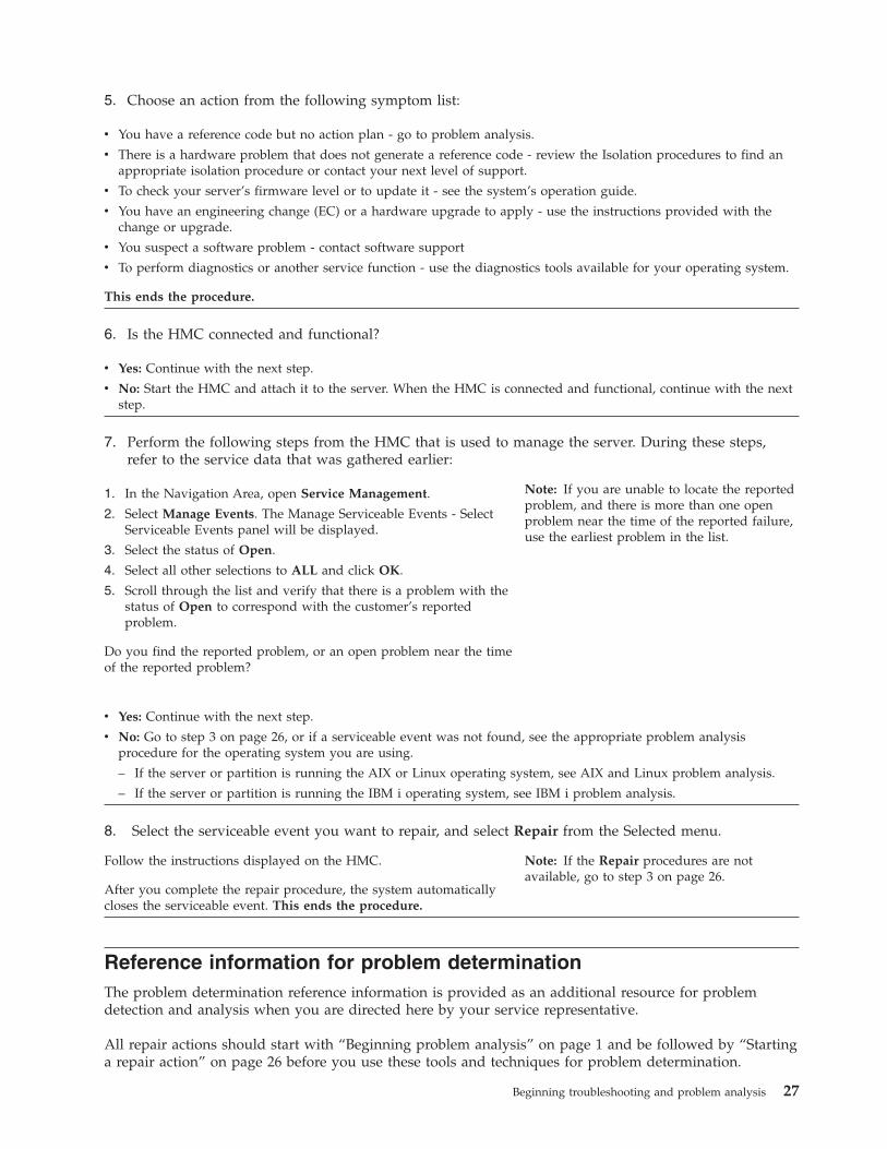
5. Choose an action from the following symptom list:
v You have a reference code but no action plan - go to problem analysis.
v There is a hardware problem that does not generate a reference code - review the Isolation procedures to find anappropriate isolation procedure or contact your next level of support.
v To check your server’s firmware level or to update it - see the system’s operation guide.
v You have an engineering change (EC) or a hardware upgrade to apply - use the instructions provided with thechange or upgrade.
v You suspect a software problem - contact software support
v To perform diagnostics or another service function - use the diagnostics tools available for your operating system.
This ends the procedure.
6. Is the HMC connected and functional?
v Yes: Continue with the next step.
v No: Start the HMC and attach it to the server. When the HMC is connected and functional, continue with the nextstep.
7. Perform the following steps from the HMC that is used to manage the server. During these steps,refer to the service data that was gathered earlier:
1. In the Navigation Area, open Service Management.
2. Select Manage Events. The Manage Serviceable Events - SelectServiceable Events panel will be displayed.
3. Select the status of Open.
4. Select all other selections to ALL and click OK.
5. Scroll through the list and verify that there is a problem with thestatus of Open to correspond with the customer’s reportedproblem.
Do you find the reported problem, or an open problem near the timeof the reported problem?
Note: If you are unable to locate the reportedproblem, and there is more than one openproblem near the time of the reported failure,use the earliest problem in the list.
v Yes: Continue with the next step.
v No: Go to step 3 on page 26, or if a serviceable event was not found, see the appropriate problem analysisprocedure for the operating system you are using.
– If the server or partition is running the AIX or Linux operating system, see AIX and Linux problem analysis.
– If the server or partition is running the IBM i operating system, see IBM i problem analysis.
8. Select the serviceable event you want to repair, and select Repair from the Selected menu.
Follow the instructions displayed on the HMC.
After you complete the repair procedure, the system automaticallycloses the serviceable event. This ends the procedure.
Note: If the Repair procedures are notavailable, go to step 3 on page 26.
Reference information for problem determinationThe problem determination reference information is provided as an additional resource for problemdetection and analysis when you are directed here by your service representative.
All repair actions should start with “Beginning problem analysis” on page 1 and be followed by “Startinga repair action” on page 26 before you use these tools and techniques for problem determination.
Beginning troubleshooting and problem analysis 27

Symptom indexUse this symptom index only when you are guided here by your service representative.
Note: If you were not guided here by your service representative, go to “Beginning problem analysis”on page 1.
Review the symptoms in the left column. Look for the symptom that most closely matches the symptomson the server that you are troubleshooting. When you find the matching symptom, perform theappropriate action as described in the right column.
Table 6. Determining symptom types
Symptom What you should do:
You do not have a symptom. Go to the Starting a repair action.
The symptom or problem is on a server or apartition running IBM i
Go to “IBM i server or IBM i partition symptoms.”
The symptom or problem is on a server or apartition running AIX.
Go to “AIX server or AIX partition symptoms” on page 31.
The symptom or problem is on a server or apartition running Linux.
Go to “Linux server or Linux partition symptoms” on page44.
IBM i server or IBM i partition symptomsUse the following tables to find the symptom you are experiencing. If you cannot find your symptom,contact your next level of support.v General symptomsv Symptoms occurring when the system is not operationalv Symptoms related to a logical partition on a server that has multiple logical partitionsv Obvious physical symptomsv Time-of-day symptoms
Table 7. General IBM i server or IBM i partition symptoms
Symptom Service action
You have an intermittent problem or you suspectthat the problem is intermittent.
Go to “Intermittent problems” on page 144.
DST/SST functions are available on the logicalpartition console and:
v The customer reports reduced system function.
v There is a server performance problem.
v There are failing, missing, or inoperable serverresources.
On most servers with logical partitions, it is common to haveone or more missing or non-reporting system bus resource’sunder Hardware Service Manager (see Hardware ServiceManager for more information).
Operations Console, or the remote control panel isnot working properly.
Contact Software Support.
The system has a processor or memory problem. Use the Service action log to check for a reference code orany failing items. See Service action log for instructions,replacing any hardware FRUs if necessary.
The system has detected a bus problem. An SRC ofthe form B600 69xx or B700 69xx will be displayedon the control panel or HMC.
Go to Service action log.
28

Table 8. Symptoms occurring when the system is not operational
Symptom Service action
A bouncing or scrolling ball (moving row of dots)remains on the operator panel display, or theoperator panel display is filled with dashes orblocks.
Verify that the operator panel connections to the systembackplane are connected and properly seated. Also, reseat theService Processor card.
If a client computer (such as a PC with Ethernet capabilityand a Web browser) is available, connect it to the serviceprocessor in the server that is displaying the symptom.
To connect a personal computer with Ethernet capability anda Web browser, or an ASCII terminal, to access the AdvancedSystem Management Interface (ASMI), go to Managing yourserver using the Advanced System Management Interface.
v If you can successfully access the ASMI, replace theoperator panel assembly. Refer to Finding parts, locations,and addresses to determine the part number and correctexchange procedure.
v If you cannot successfully access the ASMI, replace theservice processor. Refer to Finding parts, locations, andaddresses to determine the part number and correctexchange procedure.
If you do not have a PC or ASCII terminal, replace thefollowing one at a time (go to Finding parts, locations, andaddresses to determine the part number and correct exchangeprocedure):
1. Operator panel assembly.
2. Service processor.
You have a blank display on the operator panel.Other LEDs on the operator panel appear to behavenormally.
Verify that the operator panel connections to the systembackplane are connected and properly seated.
If a client computer (such as a PC with Ethernet capabilityand a Web browser) is available, connect it to the serviceprocessor in the server that is displaying the symptom.
To connect a personal computer with Ethernet capability anda Web browser, or an ASCII terminal, to access the AdvancedSystem Management Interface (ASMI), go to Managing yourserver using the Advanced System Management Interface.
v If you can successfully access the ASMI, replace theoperator panel assembly. Refer to Finding parts, locations,and addresses to determine the part number and correctexchange procedure.
v If you cannot successfully access the ASMI, replace theservice processor. Refer to Finding parts, locations, andaddresses to determine the part number and correctexchange procedure.
If you do not have a PC or ASCII terminal, replace thefollowing one at a time (go to Finding parts, locations, andaddresses to determine the part number and correct exchangeprocedure):
1. Control (operator) panel assembly.
2. Service processor.
Beginning troubleshooting and problem analysis 29

Table 8. Symptoms occurring when the system is not operational (continued)
Symptom Service action
There is an IPL problem, the system attention lightis on, and blocks of data appear for 5 seconds at atime before moving to the next block of data for 5seconds, and so on until 5 seconds of a blank controlpanel is displayed at which time the cycle repeats.
These blocks of data are functions 11 through 20. The firstdata block after the blank screen is function 11, the secondblock is function 12, and so on. Use this information to fillout the Problem reporting forms. Then go to Reference codes.
You have a power problem, the system or anattached unit will not power on or will not poweroff, or there is a 1xxx-xxxx reference code.
Go to Power problems.
There is an SRC in function 11. Look up the reference code (see Reference codes).
There is an IPL problem. Go to “IPL problems” on page 149.
There is a Device Not Found message during aninstallation from an alternate installation device.
Go to TUPIP06.
Table 9. Symptoms related to a logical partition on a server that has multiple logical partitions
Symptom Service action
The console is not working for a logical partition. See Recovering when the console does not show a sign-ondisplay or a menu with a command line.
v There is an SRC on the panel of an I/O expansionunit owned by a logical partition.
v You suspect a power problem with resourcesowned by a logical partition.
v There is an IPL problem with a logical partitionand there is an SRC on the HMC.
v The logical partition’s operations have stopped orthe partition is in a loop and there is an SRC onthe HMC.
v Search Service Focal Point for a serviceable event.
v If you do not find a serviceable event in Service FocalPoint, then record the partition’s SRC from the OperatorPanel Values field in the HMC:
1. In the Navigation Area, expand Server and Partition →Server Management.
2. In the right pane, expand or select your system orpartition.
3. Use that SRC and look up the reference code (seeReference codes).
The logical partition’s console is functioning, but thestate of the partition in the HMC is ″Failed″ or ″UnitAttn″ and there is an SRC.
Use the logical partition’s SRC. From the partition’s consolesearch for that SRC in the partition’s Service Action Log. SeeService action log.
There is an IPL problem with a logical partition andthere is no SRC displayed in the HMC.
Perform the following to look for the panel value for thepartition in the HMC:
1. In the Navigation Area, expand Server and Partition →Server Management.
2. In the right pane expand the system that contains thepartition.
3. Open Partitions.
4. Right-click the logical partition and select Properties.
5. Select the Reference Code tab to view the codes.
6. When finished, click Cancel.
Go to Reference codes. If no reference code could be found,contact your next level of support.
The partition’s operations have stopped or thepartition is in a loop and there is no SRC displayedon the HMC.
Perform function 21 from the HMC. If this fails to resolve theproblem, contact your next level of support.
30

Table 9. Symptoms related to a logical partition on a server that has multiple logical partitions (continued)
Symptom Service action
One or more of the following was reported:
v There is a system reference code or message onthe logical partition’s console.
v The customer reports reduced function in thepartition.
v There is a logical partition performance problem.
v There are failing, missing, or inoperable resources.
From the partition’s console search the partition’s ServiceAction Log. Go to Service action log.Note: On most systems with logical partitions, it is commonto have one or more ″Missing or Non-reporting″ system busresource’s under Hardware Service Manager. See HardwareService Manager for details.
There is a Device Not Found message during aninstallation from an alternate installation device.
Go to TUPIP06.
There is a problem with a guest partition.Note: These are problems reported from theoperating system (other than IBM i) running in aguest partition or reported from the hostingpartition of a guest partition.
If there are serviceable events in the logical partition orhosting partition, work on these problems first. If there are noSAL entries in the logical partition and no SAL entries in thehosting partition, contact your next level of support.
Table 10. Obvious physical symptoms
Symptom Service action
A power indicator light or display on the systemunit control panel or an attached I/O unit is notworking correctly.
Perform PWR1920.
One or more of the following was reported:
v Noise
v Smoke
v Odor
Go to the system safety inspection procedures for yourspecific system.
A part is broken or damaged. Go to the System parts to get the part number. Then go to theremove and replace procedures for your specific system toexchange the part.
Table 11. Time-of-day problems
Symptom Service action
System clock loses or gains more than 1 second perday when the system is connected to utility power.
Replace the service processor. See symbolic FRU SVCPROC.
System clock loses or gains more than 1 second perday when the system is disconnected from utilitypower.
Replace the time-of-day battery on the service processor. Goto symbolic FRU TOD_BAT.
AIX server or AIX partition symptomsUse the following tables to find the symptom you are experiencing. If you cannot find your symptom,contact your next level of support.
Choose the description that best describes your situation:v You have a service action to performv Integrated Virtualization Manager (IVM) Problemv An LED is not operating as expectedv Control (operator) panel problemsv Reference codesv Hardware Management Console (HMC) Problem
Beginning troubleshooting and problem analysis 31

v There is a display or monitor problem (for example, distortion or blurring)v Power and cooling problemsv Other symptoms or problems
You have a service action to perform
Symptom What you should do:
You have an open service event in the service actionevent log.
Go to Starting a repair action.
You have parts to exchange or a corrective action toperform.
1. Go to the remove and replace procedures for yourspecific server.
2. Go to Close of call procedure.
You need to verify that a part exchange or correctiveaction corrected the problem.
1. Go to Verifying the repair.
2. Go to the Close of call procedure.
You need to verify correct system operation. 1. Go to Verifying the repair.
2. Go to Close of call procedure.
Integrated Virtualization Manager (IVM) Problem
Symptom What you should do:
The partitions do not activate - partition configuration isdamaged
Restore the partition configuration data using IVM. SeeBacking up and restoring partition data
Other partition problems when the server is managed byIVM
Perform Troubleshooting with the IntegratedVirtualization Manager
An LED is not operating as expected
Symptom What you should do:
The system attention LED on the control panel is on. Go to Starting a repair action.
The rack identify LED does not operate properly. Go to AIX fast-path problem isolation.
The rack indicator LED does not turn on, but a draweridentify LED is on.
1. Make sure the rack indicator LED is properlymounted to the rack.
2. Make sure that the rack identify LED is properlycabled to the bus bar on the rack and to the draweridentify LED connector.
3. Replace the following parts one at a time:
v Rack LED to bus bar cable
v LED bus bar to drawer cable
v LED bus bar
4. Contact your next level of support
32

Control (operator) panel problems
Symptom What you should do:
01 does not appear in the upper-left corner of theoperator panel display after the power is connected andbefore pressing the power-on button. Other symptomsappear in the operator panel display or LEDs before thepower on button is pressed.
Go to Power problems.
A bouncing or scrolling ball (moving row of dots)remains on the operator panel display, or the operatorpanel display is filled with dashes or blocks.
Verify that the operator panel connections to the systembackplane are connected and properly seated. Also,reseat the Service Processor card.
If a client computer (such as a PC with Ethernetcapability and a Web browser) is available, connect it tothe service processor in the server that is displaying thesymptom.
To connect a personal computer with Ethernet capabilityand a Web browser, or an ASCII terminal, to access theAdvanced System Management Interface (ASMI), go toManaging your server using the Advanced SystemManagement Interface.
v If you can successfully access the ASMI, replace theoperator panel assembly. Refer to Finding parts,locations, and addresses to determine the part numberand correct exchange procedure.
v If you cannot successfully access the ASMI, replace theservice processor. Refer to Finding parts, locations, andaddresses to determine the part number and correctexchange procedure.
If you do not have a PC or ASCII terminal, replace thefollowing one at a time (go to Finding parts, locations,and addresses to determine the part number and correctexchange procedure):
1. Operator panel assembly.
2. Service processor.
Beginning troubleshooting and problem analysis 33

Symptom What you should do:
You have a blank display on the operator panel. OtherLEDs on the operator panel appear to behave normally.
Verify that the operator panel connections to the systembackplane are connected and properly seated.
If a client computer (such as a PC with Ethernetcapability and a Web browser) is available, connect it tothe service processor in the server that is displaying thesymptom.
To connect a personal computer with Ethernet capabilityand a Web browser, or an ASCII terminal, to access theAdvanced System Management Interface (ASMI), go toManaging your server using the Advanced SystemManagement Interface.
v If you can successfully access the ASMI, replace theoperator panel assembly. Refer to Finding parts,locations, and addresses to determine the part numberand correct exchange procedure.
v If you cannot successfully access the ASMI, replace theservice processor. Refer to Finding parts, locations, andaddresses to determine the part number and correctexchange procedure.
If you do not have a PC or ASCII terminal, replace thefollowing one at a time (go to Finding parts, locations,and addresses to determine the part number and correctexchange procedure):
1. Control (operator) panel assembly.
2. Service processor.
You have a blank display on the operator panel. OtherLEDs on the operator panel are off.
Go to Power problems.
An 888 sequence is displayed in the operator paneldisplay.
Go to AIX fast-path problem isolation.
Reference codes
Symptom What you should do:
You have an 8-digit error code displayed. Look up the reference code in the Reference codessection of the Information Center.Note: If the repair for this code does not involvereplacing a FRU (for instance, running an AIX commandthat fixes the problem or changing a hot-pluggable FRU),then update the AIX error log after the problem isresolved by performing the following steps:
1. In the online diagnostics, select Task Selection → LogRepair Action.
2. Select resource sysplanar0.
On systems with a fault indicator LED, this changes thefault indicator LED from the fault state to the normalstate.
The system stops with an 8-digit error code displayedwhen booting.
Look up the reference code in the Reference codessection of the information center.
The system stops and a 4-digit code displays on thecontrol panel that does not begin with 0 or 2.
Look up the reference code in the Reference codessection of the information center.
34

Symptom What you should do:
The system stops and a 4-digit code displays on thecontrol panel that begins with 0 or 2 is displayed in theoperator panel display.
Record SRN 101-xxxx where xxxx is the 4-digit codedisplayed in the control panel, then look up thisreference code in the Reference codes section of theinformation center. Follow the instructions given in theDescription and Action column for your SRN.
The system stops and a 3-digit number displays on thecontrol panel.
Add 101– to the left of the three digits to create an SRN,then look up this reference code in the Reference codessection of the information center. Follow the instructionsgiven in the Description and Action column for yourSRN.
If there is a location code displayed under the 3-digiterror code, look at the location to see if it matches thefailing component that the SRN pointed to. If they donot match, perform the action given in the error codetable. If the problem still exists, replace the failingcomponent from the location code.
If there is a location code displayed under the 3-digiterror code, record the location code.
Record SRN 101-xxx, where xxx is the 3-digit numberdisplayed in the operator panel display, then look up thisreference code in the Reference codes section of theinformation center. Follow the instructions given in theDescription and Action column for your SRN.
Beginning troubleshooting and problem analysis 35

Hardware Management Console (HMC) Problem
Symptom What you should do:
Hardware Management Console (HMC) cannot be usedto manage a managed system, or the connection to themanaged system is failing.
If the managed system is operating normally (no errorcodes or other symptoms), the HMC might have aproblem, or the connection to the managed system mightbe damaged or incorrectly cabled. Do the following:
1. Check the connections between the HMC and themanaged system. Correct any cabling errors if found.If another cable is available, connect it in place of theexisting cable and refresh the HMC interface. Youmay have to wait up to 30 seconds for the managedsystem to reconnect.
2. Verify that any connected HMC is connected to themanaged system by checking the ManagementEnvironment of the HMC.Note: The managed system must have powerconnected, and either be waiting for a power-oninstruction (01 is in the upper-left corner of theoperator panel), or be running.
If the managed system does not appear in theNavigation area of the HMC ManagementEnvironment, the HMC or the connection to themanaged system might be failing.
3. Go to the Entry MAP in the Managing your serverusing the Hardware Management Console section.
4. There might be a problem with the service processorcard or the system backplane. If you cannot fix theproblem using the HMC tests in the Managing yourserver using the Hardware Management Consolesection:
a. Replace the service processor card. Refer to theremove and replace procedures for your specificsystem.
b. Replace the system backplane if not alreadyreplaced in substep ″a″ above. Refer to theremove and replace procedures for your specificsystem.
Hardware Management Console (HMC) cannot call outusing the attached modem and the customer’s telephoneline.
If the managed system is operating normally (no errorcodes or other symptoms), the HMC might have aproblem, or the connection to the modem and telephoneline might have a problem. Do the following:
1. Check the connections between the HMC and themodem and telephone line. Correct any cablingerrors if found.
2. Go to the Entry MAP in the Managing your serverusing the Hardware Management Console section.
36

There is a display problem (for example, distortion or blurring)
Symptom What you should do:
All display problems. 1. If you are using the Hardware Management Console,go to the Managing your server using the HardwareManagement Console section.
2. If you are using a graphics display:
a. Go to the problem determination procedures forthe display.
b. If you do not find a problem:
v Replace the graphics display adapter. Refer tothe remove and replace procedures for yourspecific system.
v Replace the backplane into which the card isplugged. Refer to the remove and replaceprocedures for your specific system.
3. If you are using an ASCII terminal:
a. Make sure that the ASCII terminal is connected toS1.
b. If problems persist, go to the problemdetermination procedures for the terminal.
c. If you do not find a problem, replace the serviceprocessor. Refer to the remove and replaceprocedures for your specific system.
There appears to be a display problem (distortion,blurring, and so on)
Go to the problem determination procedures for thedisplay.
Power and cooling problems
Symptom What you should do:
The system will not power on and no error codes areavailable.
Go to Power problems.
The power LEDs on the operator panel and the powersupply do not come on or stay on.
1. Check the service processor error log.
2. Go to Power problems.
The power LEDs on the operator panel and the powersupply come on and stay on, but the system does notpower on.
1. Check the service processor error log.
2. Go to Power problems.
A rack or a rack-mounted unit will not power on. 1. Check the service processor error log.
2. Go to Power problems.
The cooling fan(s) do not come on, or come on but donot stay on.
1. Check the service processor error log.
2. Go to Power problems.
The system attention LED on the operator panel is onand there is no error code displayed.
1. Check the service processor error log.
2. Go to Power problems.
Other symptoms or problems
Symptom What you should do:
The system stopped and a code is displayed on theoperator panel.
Go to Starting a repair action.
Beginning troubleshooting and problem analysis 37

Symptom What you should do:
01 is displayed in the upper-left corner of the operatorpanel and the fans are off.
The service processor is ready. The system is waiting forpower-on. Boot the system. If the boot is unsuccessful,and the system returns to the default display (indicatedby 01 in the upper-left corner of the operator panel), goto MAP 0200: Problem determination procedure.
The operator panel displays STBY. The service processor is ready. The server was shut downby the operating system and is still powered on. Thiscondition can be requested by a privileged system userwith no faults. Go to Starting a repair action.Note: See the service processor error log for possibleoperating system fault indications.
All of the system POST indicators are displayed on thefirmware console, the system pauses and then restarts.The term POST indicators refers to the device mnemonics(the words memory, keyboard, network, scsi, and speaker)that appear on the firmware console during thepower-on self-test (POST).
Go to Problems with loading and starting the operatingsystem.
The system stops and all of the POST indicators aredisplayed on the firmware console. The term POSTindicators refers to the device mnemonics (the wordsmemory, keyboard, network, scsi, and speaker) thatappear on the firmware console during the power-onself-test (POST).
Go to Problems with loading and starting the operatingsystem.
The system stops and the message starting softwareplease wait...is displayed on the firmware console.
Go to Problems with loading and starting the operatingsystem.
The system does not respond to the password beingentered or the system login prompt is displayed whenbooting in service mode.
1. If the password is being entered from the HardwareManagement Console (HMC), go to the Managingyour server using the Hardware ManagementConsole.
2. If the password is being entered from a keyboardattached to the system, the keyboard or its controllermay be faulty. In this case, replace these parts in thefollowing order:
a. Keyboard
b. Service processor
3. If the password is being entered from an ASCIIterminal, use the problem determination proceduresfor the ASCII terminal. Make sure the ASCII terminalis connected to S1.
If the problem persists, replace the service processor.
If the problem is fixed, go to “MAP 0410: Repaircheckout” on page 41.
The system stops with a prompt to enter a password. Enter the password. You cannot continue until a correctpassword has been entered. When you have entered avalid password, go to the beginning of this table andwait for one of the other conditions to occur.
The system does not respond when the password isentered.
Go to Step 1020-2.
38

Symptom What you should do:
No codes are displayed on the operator panel within afew seconds of turning on the system. The operatorpanel is blank before the system is powered on.
Reseat the operator panel cable. If the problem is notresolved, replace in the following order:
1. Operator panel assembly. Refer to the remove andreplace procedures for your specific system
2. Service processor. Refer to the remove and replaceprocedures for your specific system.
If the problem is fixed, go to “MAP 0410: Repaircheckout” on page 41.
If the problem is still not corrected, go to MAP 0200:Problem determination procedure.
The SMS configuration list or boot sequence selectionmenu shows more SCSI devices attached to acontroller/adapter than are actually attached.
A device may be set to use the same SCSI bus ID as thecontrol adapter. Note the ID being used by thecontroller/adapter (this can be checked and/or changedthrough an SMS utility), and verify that no deviceattached to the controller is set to use that ID.
If settings do not appear to be in conflict:
1. Go to MAP 0200: Problem determination procedure.
2. Replace the SCSI cable.
3. Replace the device.
4. Replace the SCSI adapter
Note: In a ″twin-tailed″ configuration where there ismore than one initiator device (normally another system)attached to the SCSI bus, it may be necessary to use SMSutilities to change the ID of the SCSI controller oradapter.
You suspect a cable problem. Go to Adapters, Devices and Cables for Multiple BusSystems.Note: The above link will take you to the home page ofthe pSeries® and AIX Information Center. To access thedocument mentioned above, do the following:
1. Select the continent (for example, North America)
2. Select one of the three languages listed from the AIXlisting (for example, English)
3. Select ″Hardware Documentation″ from thenavigation bar, located on the left side of the screen.
4. In the ″Hardware Documentation″ window, go to the″general service documentation″ section and select″Adapters, Devices, and Cable″.
5. Select ″Adapters, Devices and Cable Information forMultiple Bus Systems.
You have a problem that does not prevent the systemfrom booting. The operator panel is functional and therack indicator LED operates as expected.
Go to MAP 0200: Problem determination procedure.
All other symptoms. Go to MAP 0200: Problem determination procedure.
All other problems. Go to MAP 0200: Problem determination procedure.
You do not have a symptom. Go to MAP 0200: Problem determination procedure.
You have parts to exchange or a corrective action toperform.
1. Go to Starting a repair action.
2. Go to Close of call procedure.
Beginning troubleshooting and problem analysis 39

Symptom What you should do:
You need to verify that a part exchange or correctiveaction corrected the problem.
Go to “MAP 0410: Repair checkout” on page 41.
You need to verify correct system operation. Go to “MAP 0410: Repair checkout” on page 41.
The system stopped. A POST indicator is displayed onthe system console and an eight-digit error code is notdisplayed.
If the POST indicator represents:
1. Memory, go to PFW 1548: Memory and processorsubsystem problem isolation procedure.
2. Keyboard
a. Replace the keyboard.
b. Replace the service processor, location: modeldependent.
c. Go to PFW 1548: Memory and processorsubsystem problem isolation procedure.
3. Network, go to PFW 1548: Memory and processorsubsystem problem isolation procedure.
4. SCSI, go to PFW 1548: Memory and processorsubsystem problem isolation procedure.
5. Speaker
a. Replace the control panel. The location is modeldependent; refer to Installing features
b. Replace the service processor. The location ismodel dependent.
c. Go to PFW 1548: Memory and processorsubsystem problem isolation procedure.
The diagnostic operating instructions are displayed. Go to MAP 0200: Problem determination procedure.
The system login prompt is displayed. If you are loading the diagnostics from a CD-ROM, youmay not have pressed the correct key or you may nothave pressed the key soon enough when you were tryingto indicate a service mode IPL of the diagnosticprograms. If this is the case, try to boot the CD-ROMagain and press the correct key.Note: Perform the system shutdown procedure beforeturning off the system.
If you are sure you pressed the correct key in a timelymanner, go to Step 1020-2.
If you are loading diagnostics from a NetworkInstallation Management (NIM) server, check for thefollowing:
v The bootlist on the client may be incorrect.
v Cstate on the NIM server may be incorrect.
v There may be network problems preventing you fromconnecting to the NIM server.
Verify the settings and the status of the network. If youcontinue to have problems refer to Problems withloading and starting the operating system and follow thesteps for network boot problems.
40

Symptom What you should do:
The System Management Services (SMS) menu isdisplayed when you were trying to boot standalone AIXdiagnostics.
If you are loading diagnostics from the CD-ROM, youmay not have pressed the correct key when you weretrying to indicate a service mode IPL of the diagnosticprograms. If this is the case, try to boot the CD-ROMagain and press the correct key.
If you are sure you pressed the correct key, the device ormedia you are attempting to boot from may be faulty.
1. Try to boot from an alternate boot device connectedto the same controller as the original boot device. Ifthe boot succeeds, replace the original boot device(for removable media devices, try the media first).
If the boot fails, go to Problems with loading andstarting the operating system.
2. Go to PFW 1548: Memory and processor subsystemproblem isolation procedure.
The SMS boot sequence selection menu or remote IPLmenu does not show all of the bootable devices in thepartition or system.
If an AIX or Linux partition is being booted, verify thatthe devices that you expect to see in the list are assignedto this partition. If they are not, use the HMC to reassignthe required resources. If they are assigned to thispartition, go to Problems with loading and starting theoperating system to resolve the problem.
MAP 0410: Repair checkout:
Use this MAP to check out the server after a repair is completed.
Purpose of this MAP
Use this MAP to check out the server after a repair is completed.
Note: Only use standalone diagnostics for repair verification when no other diagnostics are available onthe system. Standalone diagnostics do not log repair actions.
If you are servicing an SP™ system, go to the End-of-call MAP in the SP System Service Guide.
If you are servicing a clustered eServer™, go to the End of Call MAP in the Clustered eServer Installationand Service Guide.v Step 0410-1
Did you use an AIX diagnostics service aid hot-swap operation to change the FRU?
NO Go to Step 0410-2.
YES Go to Step 0410-4.v Step 0410-2
Note: If the system planar or battery has been replaced and you are loading diagnostics from a serverover a network, it may be necessary for the customer to set the network boot information for thissystem before diagnostics can be loaded. The system time and date information should also be setwhen the repair is completed.Do you have any FRUs (for example cards, adapters, cables, or devices) that were removed duringproblem analysis that you want to put back into the system?
NO Go to Step 0410-3.
Beginning troubleshooting and problem analysis 41

YES Reinstall all of the FRUs that were removed during problem analysis. Go to Step 0410-3.v Step 0410-3
Is the system or logical partition that you are performing a repair action on running the AIXoperating system?
NO Go to Step 0410-5.
YES Go to Step 0410-4.v Step 0410-4
Does the system or logical partition you are performing a repair action on have AIX installed?
Note: Answer ″NO″ to this question if you have just replaced a hard disk in the root volume group.
NO Go to Step 0410-5.
YES Go to Step 0410-6.v Step 0410-5
Run standalone diagnostics from either a CD ROM or from a NIM server.Did you encounter any problems?
NO Go to Step 0410-14.
YES Go to MAP 0020: Problem determination procedure.v Step 0410-6
1. If the system supports slow boot (See Performing a slow boot), do a slow boot on the system. If thesystem does not support slow boot, do a normal boot.
2. Power on the system.3. Wait until the AIX operating system login prompt displays or until system activity on the operator
panel or display apparently has stopped.Did the AIX Login Prompt display?
NO Go to MAP 0020: Problem determination procedure.
YES Go to Step 0410-7.v Step 0410-7
If the Resource Repair Action menu is already displayed, go to Step 0410-10; otherwise, do thefollowing:1. Log into the operating system either with root authority (if needed, ask the customer to enter the
password) or use the CE login.2. Enter the diag -a command and check for missing resources. Follow any instructions that display.
If an SRN displays, suspect a loose card or connection. If no instructions display, no resources weredetected as missing. Continue on to Step 0410-8
v Step 0410-8
1. Enter diag at the command prompt.2. Press Enter.3. Select the Diagnostics Routines option.4. When the DIAGNOSTIC MODE SELECTION menu displays, select Problem determination.5. When the ADVANCED DIAGNOSTIC SELECTION menu displays, select the All Resources option
or test the FRUs you exchanged, and any devices that are attached to the FRU(s) you exchanged, byselecting the diagnostics for the individual FRU.
Did the RESOURCE REPAIR ACTION menu (801015) display?
NO Go to Step 0410-9.
YES Go to Step 0410-10.
42

v Step 0410-9
Did the TESTING COMPLETE, no trouble was found menu (801010) display?
NO There is still a problem. Go to MAP 0020: Problem determination procedure.
YES Use the Log Repair Action option, if not previously logged, in the TASK SELECTION menu toupdate the AIX error log. If the repair action was reseating a cable or adapter, select theresource associated with that repair action.
If the resource associated with your action is not displayed on the resource list, selectsysplanar0.
Note: If the system attention indicator is on, this will set it back to the normal state.
Go to Step 0410-12.v Step 0410-10
When a test is run on a resource in system verification mode, and that resource has an entry in the AIXerror log, if the test on the resource was successful, the RESOURCE REPAIR ACTION menu displays.After replacing a FRU, you must select the resource for that FRU from the RESOURCE REPAIRACTION menu. This updates the AIX error log to indicate that a system-detectable FRU has beenreplaced.
Note: If the system attention indicator is on, this action will set it back to the normal state.Do the following:1. Select the resource that has been replaced from the RESOURCE REPAIR ACTION menu. If the
repair action was reseating a cable or adapter, select the resource associated with that repair action.If the resource associated with your action is not displayed on the resource list, select sysplanar0.
2. Press Commit after you make your selections.Did another Resource Repair Action (801015) display?
NO If the No Trouble Found menu displays, go to Step 0410-12.
YES Go to Step 0410-11.v Step 0410-11
The parent or child of the resource you just replaced may also require that you run the RESOURCEREPAIR ACTION service aid on it.When a test is run on a resource in system verification mode, and that resource has an entry in the AIXerror log, if the test on the resource was successful, the RESOURCE REPAIR ACTION menu displays.After replacing that FRU, you must select the resource for that FRU from the RESOURCE REPAIRACTION menu. This updates the AIX error log to indicate that a system-detectable FRU has beenreplaced.
Note: If the system attention indicator is on, this action will set it back to the normal state.Do the following:1. From the RESOURCE REPAIR ACTION menu, select the parent or child of the resource that has
been replaced . If the repair action was reseating a cable or adapter, select the resource associatedwith that repair action. If the resource associated with your action is not displayed on the resourcelist, select sysplanar0.
2. Press COMMIT after you make your selections.3. If the No Trouble Found menu displays, go to Step 0410-12.
v Step 0410-12
If you changed the service processor or network settings, as instructed in previous MAPs, restore thesettings to the value they had prior to servicing the system. If you ran standalone diagnostics fromCD-ROM, remove the standalone diagnostics CD-ROM from the system.
Beginning troubleshooting and problem analysis 43

Did you perform service on a RAID subsystem involving changing of the PCI RAID adapter cachecard or changing the configuration?
Note: This does not refer to the PCI-X RAID adapter or cache.
NO Go to Step 0410-14.
YES Go to Step 0410-13.v Step 0410-13
Use the Recover Options selection to resolve the RAID configuration. To do this, do the following:1. On the PCI SCSI Disk Array Manager screen, select Recovery options.2. If a previous configuration exists on the replacement adapter, this must be cleared. Select Clear PCI
SCSI Adapter Configuration. Press F3.3. On the Recovery Options screen, select Resolve PCI SCSI RAID Adapter Configuration.4. On the Resolve PCI SCSI RAID Adapter Configuration screen, select Accept Configuration on
Drives.5. On the PCI SCSI RAID Adapter selections menu, select the adapter that you changed.6. On the next screen, press Enter.7. When you get the Are You Sure selection menu, press Enter to continue.8. You should get an OK status message when the recover is complete. If you get a Failed status
message, verify that you selected the correct adapter, then repeat this procedure. When recover iscomplete, exit the operating system.
9. Go to Step 0410-14.v Step 0410-14
If the system you are servicing has a Hardware Management Console (HMC) with Service Focal Point(SFP), go to the end-of-call procedure for systems with Service Focal Point.
This completes the repair; return the server to the customer.
Linux server or Linux partition symptomsUse the following tables to find the symptom you are experiencing. If you cannot find your symptom,contact your next level of support.
Choose the description that best describes your situation:v You have a service action to performv Integrated Virtualization Manager (IVM) Problemv An LED is not operating as expectedv Control (operator) panel problemsv Reference codesv Hardware Management Console (HMC) Problemv There is a display or monitor problem (for example, distortion or blurring)v Power and cooling problemsv Other symptoms or problems
You have a service action to perform
Symptom What you should do:
You have an open service event in the service actionevent log.
Go to Starting a repair action.
44
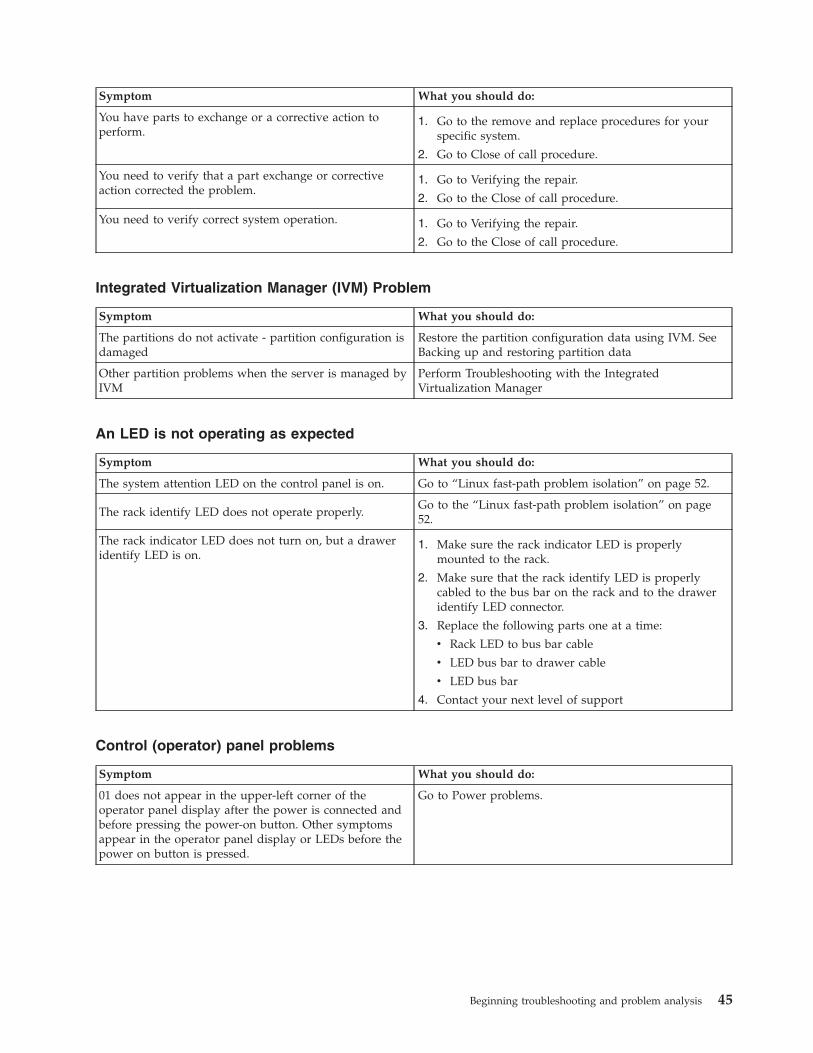
Symptom What you should do:
You have parts to exchange or a corrective action toperform.
1. Go to the remove and replace procedures for yourspecific system.
2. Go to Close of call procedure.
You need to verify that a part exchange or correctiveaction corrected the problem.
1. Go to Verifying the repair.
2. Go to the Close of call procedure.
You need to verify correct system operation. 1. Go to Verifying the repair.
2. Go to the Close of call procedure.
Integrated Virtualization Manager (IVM) Problem
Symptom What you should do:
The partitions do not activate - partition configuration isdamaged
Restore the partition configuration data using IVM. SeeBacking up and restoring partition data
Other partition problems when the server is managed byIVM
Perform Troubleshooting with the IntegratedVirtualization Manager
An LED is not operating as expected
Symptom What you should do:
The system attention LED on the control panel is on. Go to “Linux fast-path problem isolation” on page 52.
The rack identify LED does not operate properly.Go to the “Linux fast-path problem isolation” on page52.
The rack indicator LED does not turn on, but a draweridentify LED is on.
1. Make sure the rack indicator LED is properlymounted to the rack.
2. Make sure that the rack identify LED is properlycabled to the bus bar on the rack and to the draweridentify LED connector.
3. Replace the following parts one at a time:
v Rack LED to bus bar cable
v LED bus bar to drawer cable
v LED bus bar
4. Contact your next level of support
Control (operator) panel problems
Symptom What you should do:
01 does not appear in the upper-left corner of theoperator panel display after the power is connected andbefore pressing the power-on button. Other symptomsappear in the operator panel display or LEDs before thepower on button is pressed.
Go to Power problems.
Beginning troubleshooting and problem analysis 45

Symptom What you should do:
A bouncing or scrolling ball (moving row of dots)remains on the operator panel display, or the operatorpanel display is filled with dashes or blocks.
Verify that the operator panel connections to the systembackplane are connected and properly seated. Also,reseat the Service Processor card.
If a client computer (such as a PC with Ethernetcapability and a Web browser) is available, connect it tothe service processor in the server that is displaying thesymptom.
To connect a personal computer with Ethernet capabilityand a Web browser, or an ASCII terminal, to access theAdvanced System Management Interface (ASMI), go toManaging your server using the Advanced SystemManagement Interface.
v If you can successfully access the ASMI, replace theoperator panel assembly. Refer to Finding parts,locations, and addresses to determine the part numberand correct exchange procedure.
v If you cannot successfully access the ASMI, replace theservice processor. Refer to Finding parts, locations, andaddresses to determine the part number and correctexchange procedure.
If you do not have a PC or ASCII terminal, replace thefollowing one at a time (go to Finding parts, locations,and addresses to determine the part number and correctexchange procedure):
1. Operator panel assembly.
2. Service processor.
You have a blank display on the operator panel. OtherLEDs on the operator panel appear to behave normally.
Verify that the operator panel connections to the systembackplane are connected and properly seated.
If a client computer (such as a PC with Ethernetcapability and a Web browser) is available, connect it tothe service processor in the server that is displaying thesymptom.
To connect a personal computer with Ethernet capabilityand a Web browser, or an ASCII terminal, to access theAdvanced System Management Interface (ASMI), go toManaging your server using the Advanced SystemManagement Interface.
v If you can successfully access the ASMI, replace theoperator panel assembly. Refer to Finding parts,locations, and addresses to determine the part numberand correct exchange procedure.
v If you cannot successfully access the ASMI, replace theservice processor. Refer to Finding parts, locations, andaddresses to determine the part number and correctexchange procedure.
If you do not have a PC or ASCII terminal, replace thefollowing one at a time (go to Finding parts, locations,and addresses to determine the part number and correctexchange procedure):
1. Control (operator) panel assembly.
2. Service processor.
46

Symptom What you should do:
You have a blank display on the operator panel. OtherLEDs on the operator panel are off.
Go to Power problems.
Reference codes
Symptom What you should do:
You have an 8-digit error code displayed. Look up the reference code in the Reference codessection of the information center.Note: If the repair for this code does not involvereplacing a FRU (for instance, running an AIX commandthat fixes the problem or changing a hot-pluggable FRU),then update the AIX error log after the problem isresolved by performing the following steps:
1. In the online diagnostics, select Task SelectionLogRepair Action.
2. Select resource sysplanar0.
On systems with a fault indicator LED, this changes the″fault indicator″ LED from the ″fault″ state to the″normal″ state.
The system stops with an 8-digit error code displayedwhen booting.
Look up the reference code in the Reference codessection of the information center.
The system stops and a 4-digit code displays on thecontrol panel that does not begin with 0 or 2.
Look up the reference code in the Reference codessection of the information center.
The system stops and a 4-digit code displays on thecontrol panel that begins with 0 or 2 is displayed in theoperator panel display.
Record SRN 101-xxxx where xxxx is the 4-digit codedisplayed in the control panel, then look up thisreference code in the Reference codes section of theinformation center. Follow the instructions given in theDescription and Action column for your SRN.
The system stops and a 3-digit number displays on thecontrol panel.
Add 101– to the left of the three digits to create an SRN,then look up this reference code in the Reference codessection of the information center. Follow the instructionsgiven in the Description and Action column for yourSRN.
If there is a location code displayed under the 3-digiterror code, look at the location to see if it matches thefailing component that the SRN pointed to. If they donot match, perform the action given in the error codetable. If the problem still exists, then replace the failingcomponent from the location code.
If there is a location code displayed under the 3-digiterror code, record the location code.
Record SRN 101-xxx, where xxx is the 3-digit numberdisplayed in the operator panel display, then look up thisreference code in the Reference codes section of theinformation center. Follow the instructions given in theDescription and Action column for your SRN.
Beginning troubleshooting and problem analysis 47

Hardware Management Console (HMC) Problem
Symptom What you should do:
Hardware Management Console (HMC) cannot be usedto manage a managed system, or the connection to themanaged system is failing.
If the managed system is operating normally (no errorcodes or other symptoms), the HMC might have aproblem, or the connection to the managed system mightbe damaged or incorrectly cabled. Do the following:
1. Check the connections between the HMC and themanaged system. Correct any cabling errors if found.If another cable is available, connect it in place of theexisting cables and refresh the HMC interface. Youmay have to wait up to 30 seconds for the managedsystem to reconnect.
2. Verify that any connected HMC is connected to themanaged system by checking the ManagementEnvironment of the HMC.Note: The managed system must have powerconnected and the system running, or waiting for apower-on instruction (01 is in the upper-left corner ofthe operator panel.)
If the managed system does not appear in theNavigation area of the HMC ManagementEnvironment, the HMC or the connection to themanaged system might be failing.
3. Go to the Managing your server using the HardwareManagement Console section.
4. There might be a problem with the service processorcard or the HMC system backplane. If you cannot fixthe problem using the HMC tests in the Managingyour server using the Hardware ManagementConsole section:
a. Replace the service processor card. Refer to theremove and replace procedures for your specificsystem.
b. Replace the HMC system backplane. Refer to theremove and replace procedures for your specificsystem.
Hardware Management Console (HMC) cannot call outusing the attached modem and the customer’s telephoneline.
If the managed system is operating normally (no errorcodes or other symptoms), the HMC might have aproblem, or the connection to the modem and telephoneline might have a problem. Do the following:
1. Check the connections between the HMC and themodem and telephone line. Correct any cablingerrors if found.
2. Go to the Managing your server using the HardwareManagement Console for information about theHMC.
48
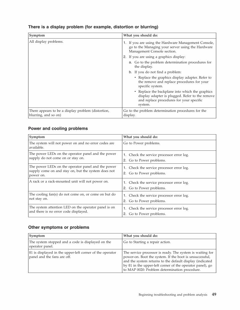
There is a display problem (for example, distortion or blurring)
Symptom What you should do:
All display problems. 1. If you are using the Hardware Management Console,go to the Managing your server using the HardwareManagement Console section.
2. If you are using a graphics display:
a. Go to the problem determination procedures forthe display.
b. If you do not find a problem:
v Replace the graphics display adapter. Refer tothe remove and replace procedures for yourspecific system.
v Replace the backplane into which the graphicsdisplay adapter is plugged. Refer to the removeand replace procedures for your specificsystem.
There appears to be a display problem (distortion,blurring, and so on)
Go to the problem determination procedures for thedisplay.
Power and cooling problems
Symptom What you should do:
The system will not power on and no error codes areavailable.
Go to Power problems.
The power LEDs on the operator panel and the powersupply do not come on or stay on.
1. Check the service processor error log.
2. Go to Power problems.
The power LEDs on the operator panel and the powersupply come on and stay on, but the system does notpower on.
1. Check the service processor error log.
2. Go to Power problems.
A rack or a rack-mounted unit will not power on. 1. Check the service processor error log.
2. Go to Power problems.
The cooling fan(s) do not come on, or come on but donot stay on.
1. Check the service processor error log.
2. Go to Power problems.
The system attention LED on the operator panel is onand there is no error code displayed.
1. Check the service processor error log.
2. Go to Power problems.
Other symptoms or problems
Symptom What you should do:
The system stopped and a code is displayed on theoperator panel.
Go to Starting a repair action.
01 is displayed in the upper-left corner of the operatorpanel and the fans are off.
The service processor is ready. The system is waiting forpower-on. Boot the system. If the boot is unsuccessful,and the system returns to the default display (indicatedby 01 in the upper-left corner of the operator panel), goto MAP 0020: Problem determination procedure.
Beginning troubleshooting and problem analysis 49

Symptom What you should do:
The operator panel displays STBY. The service processor is ready. The server was shut downby the operating system and is still powered on. Thiscondition can be requested by a privileged system userwith no faults. Go to Starting a repair action.Note: See the service processor error log for possibleoperating system fault indications.
All of the system POST indicators are displayed on thefirmware console, the system pauses and then restarts.The term POST indicators refers to the device mnemonics(the words memory, keyboard, network, scsi, and speaker)that appear on the firmware console during thepower-on self-test (POST).
Go to Problems with loading and starting the operatingsystem.
The system stops and all of the POST indicators aredisplayed on the firmware console. The term POSTindicators refers to the device mnemonics (the wordsmemory, keyboard, network, scsi, and speaker) thatappear on the firmware console during the power-onself-test (POST).
Go to Problems with loading and starting the operatingsystem.
The system stops and the message starting softwareplease wait...is displayed on the firmware console.
Go to Problems with loading and starting the operatingsystem.
The system does not respond to the password beingentered or the system login prompt is displayed whenbooting in service mode.
1. If the password is being entered from the HardwareManagement Console (HMC), go to the Managingyour server using the Hardware ManagementConsole.
2. If the password is being entered from a keyboardattached to the system, the keyboard or its controllermay be faulty. In this case, replace these parts in thefollowing order:
a. Keyboard
b. Service processor
If the problem is fixed, go to “MAP 0410: Repaircheckout” on page 41.
The system stops with a prompt to enter a password. Enter the password. You cannot continue until a correctpassword has been entered. When you have entered avalid password, go to the beginning of this table andwait for one of the other conditions to occur.
The system does not respond when the password isentered.
Go to Step 1020-2.
No codes are displayed on the operator panel within afew seconds of turning on the system. The operatorpanel is blank before the system is powered on.
Reseat the operator panel cable. If the problem is notresolved, replace in the following order:
1. Operator panel assembly. Refer to the remove andreplace procedures for your specific system
2. Service processor. Refer to the remove and replaceprocedures for your specific system.
If the problem is fixed, go to “MAP 0410: Repaircheckout” on page 41.
If the problem is still not corrected, go to MAP 0020:Problem determination procedure.
50

Symptom What you should do:
The SMS configuration list or boot sequence selectionmenu shows more SCSI devices attached to acontroller/adapter than are actually attached.
A device may be set to use the same SCSI bus ID as thecontrol adapter. Note the ID being used by thecontroller/adapter (this can be checked and/or changedthrough an SMS utility), and verify that no deviceattached to the controller is set to use that ID.
If settings do not appear to be in conflict:
1. Go to MAP 0020: Problem determination procedure.
2. Replace the SCSI cable.
3. Replace the device.
4. Replace the SCSI adapter
Note: In a ″twin-tailed″ configuration where there ismore than one initiator device (normally another system)attached to the SCSI bus, it may be necessary to use SMSutilities to change the ID of the SCSI controller oradapter.
You suspect a cable problem. Go to Adapters, Devices and Cables for Multiple BusSystems.
You have a problem that does not prevent the systemfrom booting. The operator panel is functional and therack indicator LED operates as expected.
Go to MAP 0020: Problem determination procedure.
All other symptoms. Go to MAP 0020: Problem determination procedure.
All other problems. Go to MAP 0020: Problem determination procedure.
You do not have a symptom. Go to MAP 0020: Problem determination procedure.
You have parts to exchange or a corrective action toperform.
1. Go to Starting a repair action.
2. Go to Close of call procedure.
You need to verify that a part exchange or correctiveaction corrected the problem.
Go to “MAP 0410: Repair checkout” on page 41.
You need to verify correct system operation. Go to “MAP 0410: Repair checkout” on page 41.
The system stopped. A POST indicator is displayed onthe system console and an eight-digit error code is notdisplayed.
If the POST indicator represents:
1. Memory, go to PFW 1548: Memory and processorsubsystem problem isolation procedure.
2. Keyboard
a. Replace the keyboard.
b. Replace the service processor, location: modeldependent.
c. Go to PFW 1548: Memory and processorsubsystem problem isolation procedure.
3. Network, go to PFW 1548: Memory and processorsubsystem problem isolation procedure.
4. SCSI, go to PFW 1548: Memory and processorsubsystem problem isolation procedure.
5. Speaker
a. Replace the control panel. The location is modeldependent; refer to Installing features.
b. Replace the service processor. The location ismodel dependent.
c. Go to PFW 1548: Memory and processorsubsystem problem isolation procedure.
Beginning troubleshooting and problem analysis 51

Symptom What you should do:
The diagnostic operating instructions are displayed. Go to MAP 0020: Problem determination procedure.
The system login prompt is displayed. If you are loading the diagnostics from a CD-ROM, youmay not have pressed the correct key or you may nothave pressed the key soon enough when you were tryingto indicate a service mode IPL of the diagnosticprograms. If this is the case, start again at the beginningof this step.Note: Perform the system shutdown procedure beforeturning off the system.
If you are sure you pressed the correct key in a timelymanner, go to Step 1020-2.
If you are loading diagnostics from a NetworkInstallation Management (NIM) server, check for thefollowing:
v The bootlist on the client may be incorrect.
v Cstate on the NIM server may be incorrect.
v There may be network problems preventing you fromconnecting to the NIM server.
Verify the settings and the status of the network. If youcontinue to have problems refer to Problems withloading and starting the operating system and follow thesteps for network boot problems.
The System Management Services (SMS) menu isdisplayed when you were trying to boot standalonediagnostics.
If you are loading diagnostics from the CD-ROM, youmay not have pressed the correct key when you weretrying to indicate a service mode IPL of the diagnosticprograms. If this is the case, try to boot the CD-ROMagain and press the correct key.
If you are sure you pressed the correct key, the device ormedia you are attempting to boot from may be faulty.
1. Try to boot from an alternate boot device connectedto the same controller as the original boot device. Ifthe boot succeeds, replace the original boot device(for removable media devices, try the media first).
If the boot fails, go to problems with loading andstarting the operating system.
2. Go to PFW 1548: Memory and processor subsystemproblem isolation procedure.
The SMS boot sequence selection menu or remote IPLmenu does not show all of the bootable devices in thepartition or system.
If an AIX or Linux partition is being booted, verify thatthe devices that you expect to see in the list are assignedto this partition. If they are not, use the HMC to reassignthe required resources. If they are assigned to thispartition, go to Problems with loading and starting theoperating system to resolve the problem.
Linux fast-path problem isolation:
Use this information to help you isolate a hardware problem when using the Linux operating system.
Notes:
52

1. If the server or partition has an external SCSI disk drive enclosure attached and you have not beenable to find a reference code or other symptom, go to “MAP 2010: 7031-D24 or 7031-T24 START” onpage 78
2. If you are servicing an SP system, go to the Start of Call MAP 100 in the SP System Service Guide.3. If you are servicing a clustered server, go to the Start of Call MAP 100 in the Clustered Installation and
Service Guide.4. If you are servicing a clustered server that has InfiniBand switch networks, go to IBM Clusters with
the InfiniBand Switch.
Linux fast path table
Locate the problem in the following table and then go to the action indicated for the problem.
Symptoms Action
You have an eight-digit referencecode.
Go to Reference codes, and do the listed action for the eight-digit reference code.
You are trying to isolate aproblem on a Linux server or apartition that is running Linux.
Note: This procedure is used to help display an eight-digit reference code usingsystem log information. Before using this procedure, if you are having a problemwith a media device such as a tape or DVD-ROM drive, continue through thistable and follow the actions for the appropriate device. Go to “Linux problemisolation procedure” on page 56.
You suspect a problem with yourserver but you do not have anyspecific symptom.
Go to MAP 0020: Problem determination procedure for problem determinationprocedures.
You need to run the eServerstandalone diagnostics
Go to AIX diagnostics and service aids
SRNs
You have an SRN. Look up the SRN in the Service request numbers and do the listed action.
An SRN is displayed whenrunning the eServer standalonediagnostics.
1. Record the SRN and location code.
2. Look up the SRN in the Service request numbers and do the listed action.
Tape Drive Problems
You suspect a tape driveproblem.
1. Refer to the tape drive documentation and clean the tape drive.
2. Refer to the tape drive documentation and do any listed problemdetermination procedures.
3. Go to MAP 0020: Problem determination procedure for problemdetermination procedures.
4. Refer to the device section of RS/6000® eServer pSeries Adapters, Devices, andCable Information for Multiple Bus Systems for additional information (IBMeServer pSeries Information Center (http://publib16.boulder.ibm.com/pseries/en_US/infocenter/base).
Note: Information on tape cleaning and tape-problem determination is normallyeither in the tape drive operator guide or the system operator guide.
Optical Drive Problems
Beginning troubleshooting and problem analysis 53

Symptoms Action
You suspect a optical driveproblem.
1. Refer to the optical documentation and do any listed problem determinationprocedures.
2. Before servicing a optical Drive ensure that it is not in use and that thepower connector is correctly attached to the drive. If the load or unloadoperation does not function, replace the optical drive.
3. Go to MAP 0020: Problem determination procedure for problemdetermination procedures.
4. Refer to the device section of RS/6000 eServer pSeries Adapters, Devices, andCable Information for Multiple Bus Systems for additional information (IBMeServer pSeries Information Center (http://publib16.boulder.ibm.com/pseries/en_US/infocenter/base).
Note: If the optical has its own user documentation, follow any problemdetermination for the optical drive.
SCSI Disk Drive Problems
You suspect a disk driveproblem.
Disk problems are logged in theerror log and are analyzed whenthe standalone disk diagnosticsare run in problem determinationmode. Problems are reported ifthe number of errors is abovedefined thresholds.
1. Go to MAP 0020: Problem determination procedure for problemdetermination procedures.
2. Refer to the device section of RS/6000 eServer pSeries Adapters, Devices, andCable Information for Multiple Bus Systems for additional information (IBMeServer pSeries Information Center (http://publib16.boulder.ibm.com/pseries/en_US/infocenter/base).
Diskette Drive Problems
You suspect a diskette driveproblem.
1. Go to MAP 0020: Problem determination procedure for problemdetermination procedures.
Token-Ring Problems
You suspect a token-ring adapteror network problem.
1. Check with the network administrator for known problems.
2. Go to MAP 0020: Problem determination procedure for problemdetermination procedures.
Ethernet Problems
You suspect an Ethernet adapteror network problem.
1. Check with the network administrator for known problems.
2. Go to MAP 0020: Problem determination procedure for problemdetermination procedures.
Display Problems
54

Symptoms Action
You suspect a display problem. 1. If your display is connected to a KVM switch, go to Troubleshooting thekeyboard, video, and mouse (KVM) switch for the 1x8 and 2x8 consolemanager. If you are still having display problems after performing the KVMswitch procedures, come back here and continue with step 2.
2. If you are using the Hardware Management Console, go to the Managingyour server using the Hardware Management Console section.
3. If you are using a graphics display:
a. Go to the problem determination procedures for the display.
b. If you do not find a problem:
v Replace the graphics display adapter. Refer to the remove and replaceprocedures for your specific system..
v Replace the backplane into which the graphics display adapter isplugged. Refer to the remove and replace procedures for your specificsystem.
Keyboard or Mouse
You suspect a keyboard or mouseproblem.
If your keyboard is connected to a KVM switch, go to Troubleshooting thekeyboard, video, and mouse (KVM) switch for the 1x8 and 2x8 console manager.If you are still having keyboard problems after performing the KVM switchprocedures, come back here and continue to the next paragraph.Go to MAP0020: Problem determination procedure for problem determination procedures.
If you are unable to run diagnostics because the system does not respond to thekeyboard, replace the keyboard or system planar.Note: If the problem is with the keyboard it could be caused by the mousedevice. To check, unplug the mouse and then recheck the keyboard. If thekeyboard works, replace the mouse.
System Messages
A System Message is displayed. 1. If the message describes the cause of the problem, attempt to correct it.
2. Look for another symptom to use.
System Hangs or Loops When Running the OS or Diagnostics
The system hangs in the sameapplication.
Suspect the application. To check the system:
1. Power off the system.
2. Go to MAP 0020: Problem determination procedure for problemdetermination procedures.
3. If an SRN is displayed at anytime, record the SRN and location code.
4. Look up the SRN in the Service request numbers and do the listed action.
The system hangs in variousapplications.
1. Power off the system.
2. Go to MAP 0020: Problem determination procedure for problemdetermination procedures.
3. If an SRN is displayed at anytime, record the SRN and location code.
4. Look up the SRN in the Service request numbers and do the listed action.
The system hangs when runningdiagnostics.
Replace the resource that is being tested.
Exchanged FRUs Did Not Fix the Problem
A FRU or FRUs you exchangeddid not fix the problem.
Go to MAP 0020: Problem determination procedure.
RAID Problems
Beginning troubleshooting and problem analysis 55

Symptoms Action
You suspect a problem with aRAID.
A potential problem with a RAID adapter exists. Run diagnostics on the RAIDadapter. Refer to the RAID Adapters User’s Guide and Maintenance Information,refer to IBM eServer pSeries Information Center (http://publib16.boulder.ibm.com/pseries/en_US/infocenter/base)
If the RAID adapter is a PCI-X RAID adapter, refer to the PCI-X SCSI RAIDController Reference Guide for AIX in the IBM eServer pSeries Information Center(http://publib16.boulder.ibm.com/pseries/en_US/infocenter/base)
SSA Problems
You suspect an SSA problem. A potential problem with an SSA adapter exists. Run diagnostics on the SSAadapter. If the system has external SSA drives, refer to the SSA Adapters User’sGuide and Maintenance Information (IBM eServer pSeries Information Center(http://publib16.boulder.ibm.com/pseries/en_US/infocenter/base)
, or the service guide for your disk subsystem.
You Cannot Find the Symptom in This Table
All other problems. Go to MAP 0020: Problem determination procedure.
Linux problem isolation procedure:
Use this procedure when servicing a Linux partition or a server that has Linux as its only operatingsystem.
56
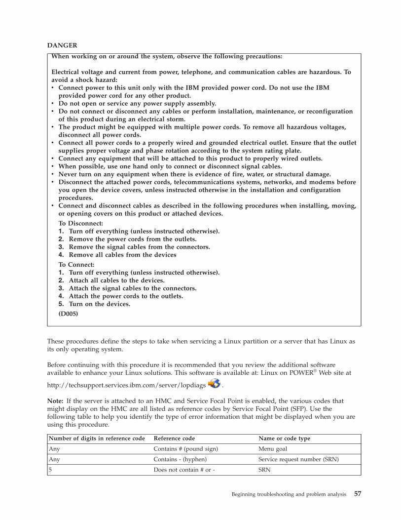
DANGER
When working on or around the system, observe the following precautions:
Electrical voltage and current from power, telephone, and communication cables are hazardous. Toavoid a shock hazard:v Connect power to this unit only with the IBM provided power cord. Do not use the IBM
provided power cord for any other product.v Do not open or service any power supply assembly.v Do not connect or disconnect any cables or perform installation, maintenance, or reconfiguration
of this product during an electrical storm.v The product might be equipped with multiple power cords. To remove all hazardous voltages,
disconnect all power cords.v Connect all power cords to a properly wired and grounded electrical outlet. Ensure that the outlet
supplies proper voltage and phase rotation according to the system rating plate.v Connect any equipment that will be attached to this product to properly wired outlets.v When possible, use one hand only to connect or disconnect signal cables.v Never turn on any equipment when there is evidence of fire, water, or structural damage.v Disconnect the attached power cords, telecommunications systems, networks, and modems before
you open the device covers, unless instructed otherwise in the installation and configurationprocedures.
v Connect and disconnect cables as described in the following procedures when installing, moving,or opening covers on this product or attached devices.
To Disconnect:1. Turn off everything (unless instructed otherwise).2. Remove the power cords from the outlets.3. Remove the signal cables from the connectors.4. Remove all cables from the devices
To Connect:1. Turn off everything (unless instructed otherwise).2. Attach all cables to the devices.3. Attach the signal cables to the connectors.4. Attach the power cords to the outlets.5. Turn on the devices.
(D005)
These procedures define the steps to take when servicing a Linux partition or a server that has Linux asits only operating system.
Before continuing with this procedure it is recommended that you review the additional softwareavailable to enhance your Linux solutions. This software is available at: Linux on POWER® Web site at
http://techsupport.services.ibm.com/server/lopdiags .
Note: If the server is attached to an HMC and Service Focal Point is enabled, the various codes thatmight display on the HMC are all listed as reference codes by Service Focal Point (SFP). Use thefollowing table to help you identify the type of error information that might be displayed when you areusing this procedure.
Number of digits in reference code Reference code Name or code type
Any Contains # (pound sign) Menu goal
Any Contains - (hyphen) Service request number (SRN)
5 Does not contain # or - SRN
Beginning troubleshooting and problem analysis 57
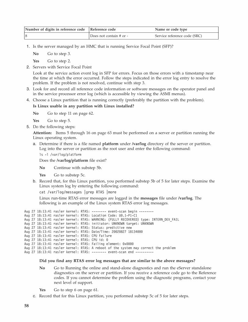
Number of digits in reference code Reference code Name or code type
8 Does not contain # or - Service reference code (SRC)
1. Is the server managed by an HMC that is running Service Focal Point (SFP)?
No Go to step 3.
Yes Go to step 2.2. Servers with Service Focal Point
Look at the service action event log in SFP for errors. Focus on those errors with a timestamp nearthe time at which the error occurred. Follow the steps indicated in the error log entry to resolve theproblem. If the problem is not resolved, continue with step 3.
3. Look for and record all reference code information or software messages on the operator panel andin the service processor error log (which is accessible by viewing the ASMI menus).
4. Choose a Linux partition that is running correctly (preferably the partition with the problem).Is Linux usable in any partition with Linux installed?
No Go to step 11 on page 62.
Yes Go to step 5.5. Do the following steps:
Attention: Items 5 through 16 on page 63 must be performed on a server or partition running theLinux operating system.a. Determine if there is a file named platform under /var/log directory of the server or partition.
Log into the server or partition as the root user and enter the following command:ls -l /var/log/platform
Does the /var/log/platform file exist?
No Continue with substep 5b.
Yes Go to substep 5c.b. Record that, for this Linux partition, you performed substep 5b of 5 for later steps. Examine the
Linux system log by entering the following command:cat /var/log/messages |grep RTAS |more
Linux run-time RTAS error messages are logged in the messages file under /var/log. Thefollowing is an example of the Linux system RTAS error log messages.
Aug 27 18:13:41 rasler kernel: RTAS: -------- event-scan begin --------Aug 27 18:13:41 rasler kernel: RTAS: Location Code: U0.1-P1-C1Aug 27 18:13:41 rasler kernel: RTAS: WARNING: (FULLY RECOVERED) type: INTERN_DEV_FAILAug 27 18:13:41 rasler kernel: RTAS: initiator: UNKNOWN target: UNKNOWNAug 27 18:13:41 rasler kernel: RTAS: Status: predictive newAug 27 18:13:41 rasler kernel: RTAS: Date/Time: 20020827 18134000Aug 27 18:13:41 rasler kernel: RTAS: CPU FailureAug 27 18:13:41 rasler kernel: RTAS: CPU id: 0Aug 27 18:13:41 rasler kernel: RTAS: Failing element: 0x0000Aug 27 18:13:41 rasler kernel: RTAS: A reboot of the system may correct the problemAug 27 18:13:41 rasler kernel: RTAS: -------- event-scan end ----------
Did you find any RTAS error log messages that are similar to the above messages?
No Go to Running the online and stand-alone diagnostics and run the eServer standalonediagnostics on the server or partition. If you receive a reference code go to the Referencecodes. If you cannot determine the problem using the diagnostic programs, contact yournext level of support.
Yes Go to step 6 on page 61.c. Record that for this Linux partition, you performed substep 5c of 5 for later steps.
58

Use the following command to list diagela messages recorded in the Linux system log:cat /var/log/platform |grep diagela |more
Linux run-time diagela error messages are logged in the platform file under /var/log.The following is an example of the Linux system error log diagela messages.
Aug 13 09:38:45 larry diagela: 08/13/2003 09:38:44Aug 13 09:38:45 larry diagela: Automatic Error Log Analysis has detected a problem.Aug 13 09:38:45 larry diagela: Aug 13 09:38:45 larry diagela: The Service RequestNumber(s)/Probable Cause(s)Aug 13 09:38:45 larry diagela: (causes are listed in descending order of probability):Aug 13 09:38:45 larry diagela:Aug 13 09:38:45 larry diagela: 651-880: The CEC or SPCN reported an error. Report theSRN and the following reference and physical location codes to your service provider.Aug 13 09:38:45 larry diagela: Location: n/a FRU: n/a Ref-Code: B1004699Aug 13 09:38:45 larry diagela:Aug 13 09:38:45 larry diagela: Analysis of Error log sequence number: 3Aug 29 07:13:04 larry diagela: 08/29/2003 07:13:04Aug 29 07:13:04 larry diagela: Automatic Error Log Analysis has detected a problem.Aug 29 07:13:04 larry diagela:Aug 29 07:13:04 larry diagela: The Service Request Number(s)/Probable Cause(s)Aug 29 07:13:04 larry diagela: (causes are listed in descending order of probability):Aug 29 07:13:04 larry diagela:Aug 29 07:13:04 larry diagela: 651-880: The CEC or SPCN reported an error. Report theSRN and the following reference and physical location codes to your service provider.Aug 29 07:13:04 larry diagela: Location: U0.1-F4 FRU: 09P5866 Ref-Code: 10117661Aug 29 07:13:04 larry diagela:Aug 29 07:13:04 larry diagela: Analysis of /var/log/platform sequence number: 24Sep 4 06:00:55 larry diagela: 09/04/2003 06:00:55Sep 4 06:00:55 larry diagela: Automatic Error Log Analysis reports the following:Sep 4 06:00:55 larry diagela:Sep 4 06:00:55 larry diagela: 651204 ANALYZING SYSTEM ERROR LOGSep 4 06:00:55 larry diagela: A loss of redundancy on input power was detected.Sep 4 06:00:55 larry diagela:Sep 4 06:00:55 larry diagela: Check for the following:Sep 4 06:00:55 larry diagela: 1. Loose or disconnected power source connections.Sep 4 06:00:55 larry diagela: 2. Loss of the power source.Sep 4 06:00:55 larry diagela: 3. For multiple enclosure systems, loose orSep 4 06:00:55 larry diagela: disconnected power and/or signal connectionsSep 4 06:00:55 larry diagela: between enclosures.Sep 4 06:00:55 larry diagela:Sep 4 06:00:55 larry diagela: Supporting data:Sep 4 06:00:55 larry diagela: Ref. Code: 10111520Sep 4 06:00:55 larry diagela: Location Codes: P1 P2Sep 4 06:00:55 larry diagela:Sep 4 06:00:55 larry diagela: Analysis of /var/log/platform sequence number: 13
d. Also use the following command to list RTAS messages recorded in the Linux system log:cat /var/log/platform |grep RTAS |more
Linux RTAS error messages are logged in the platform file under /var/log. The following is anexample of RTAS messages in the Linux system error log.
Beginning troubleshooting and problem analysis 59

Aug 27 12:16:33 larry kernel: RTAS: 15 -------- RTAS event begin --------Aug 27 12:16:33 larry kernel: RTAS 0: 04440040 000003f8 96008508 19155800Aug 27 12:16:33 larry kernel: RTAS 1: 20030827 00000001 20000000 00000000Aug 27 12:16:33 larry kernel: RTAS 2: 00000000 00000000 00000000 00000000Aug 27 12:16:33 larry kernel: RTAS 3: 49424d00 55302e31 2d463400 00503034Aug 27 12:16:33 larry kernel: RTAS 4: 10117661 04a0005d 10110000 00000000Aug 27 12:16:33 larry kernel: RTAS 5: 00007701 000000e0 00000003 000000e3Aug 27 12:16:33 larry kernel: RTAS 6: 00000000 01000000 00000000 31303131Aug 27 12:16:33 larry kernel: RTAS 7: 37363631 20202020 20202020 55302e31Aug 27 12:16:33 larry kernel: RTAS 8: 2d463420 20202020 20202020 03705a39Aug 27 12:16:33 larry kernel: RTAS 9: 00000000 00000000 00000000 00000000Aug 27 12:16:33 larry kernel: RTAS 10: 00000000 00000000 00000000 00000000Aug 27 12:16:33 larry kernel: RTAS 11: 00000000 00000000 00000000 00000000Aug 27 12:16:33 larry kernel: RTAS 12: 00000000 00000000 00000000 00000000Aug 27 12:16:33 larry kernel: RTAS 13: 00000000 00000000 00000000 00000000Aug 27 12:16:33 larry kernel: RTAS 14: 00000000 00000000 00000000 00000000Aug 27 12:16:33 larry kernel: RTAS 15: 00000000 00000000 00000000 00000000Aug 27 12:16:33 larry kernel: RTAS 16: 00000000 00000000 00000000 00000000Aug 27 12:16:33 larry kernel: RTAS 17: 00000000 00000000 00000000 00000000Aug 27 12:16:33 larry kernel: RTAS 18: 00000000 00000000 00000000 00000000Aug 27 12:16:33 larry kernel: RTAS 19: 00000000 00000000 00000000 00000000Aug 27 12:16:33 larry kernel: RTAS 20: 00000000 00000000 00000000 00000000Aug 27 12:16:33 larry kernel: RTAS 21: 00000000 00000000 00000000 00000000Aug 27 12:16:33 larry kernel: RTAS 22: 00000000 00000000 00000000 00000000Aug 27 12:16:33 larry kernel: RTAS 23: 00000000 00000000 00000000 00000000Aug 27 12:16:33 larry kernel: RTAS 24: 00000000 00000000 00000000 00000000Aug 27 12:16:33 larry kernel: RTAS 25: 00000000 00000000 00000000 00000000Aug 27 12:16:33 larry kernel: RTAS 26: 00000000 00000000 00000000 00000000Aug 27 12:16:33 larry kernel: RTAS 27: 00000000 00000000 00000000 00000000Aug 27 12:16:33 larry kernel: RTAS 28: 00000000 00000000 00000000 00000000Aug 27 12:16:33 larry kernel: RTAS 29: 00000000 00000000 00000000 00000000Aug 27 12:16:33 larry kernel: RTAS 30: 00000000 00000000 00000000 00000000Aug 27 12:16:33 larry kernel: RTAS 31: 00000000 00000000 00000000 00000000Aug 27 12:16:33 larry kernel: RTAS 32: 00000000 00000000 00000000 00000000Aug 27 12:16:33 larry kernel: RTAS 33: 00000000 00000000 00000000 00000000Aug 27 12:16:33 larry kernel: RTAS 34: 00000000 00000000 00000000 00000000Aug 27 12:16:33 larry kernel: RTAS 35: 00000000 00000000 00000000 00000000Aug 27 12:16:33 larry kernel: RTAS 36: 00000000 00000000 00000000 00000000Aug 27 12:16:33 larry kernel: RTAS 37: 00000000 00000000 00000000 00000000Aug 27 12:16:33 larry kernel: RTAS 38: 00000000 00000000 00000000 00000000Aug 27 12:16:33 larry kernel: RTAS 39: 00000000 00000000 00000000 00000000Aug 27 12:16:33 larry kernel: RTAS 40: 00000000 00000000 00000000 00000000Aug 27 12:16:33 larry kernel: RTAS 41: 00000000 00000000 00000000 00000000Aug 27 12:16:33 larry kernel: RTAS 42: 00000000 00000000 00000000 00000000Aug 27 12:16:33 larry kernel: RTAS 43: 00000000 00000000 00000000 00000000Aug 27 12:16:33 larry kernel: RTAS 44: 00000000 00000000 00000000 00000000Aug 27 12:16:33 larry kernel: RTAS 45: 00000000 00000000 00000000 00000000
60

Aug 27 12:16:33 larry kernel: RTAS 46: 00000000 00000000 00000000 00000000Aug 27 12:16:33 larry kernel: RTAS 47: 00000000 00000000 00000000 00000000Aug 27 12:16:33 larry kernel: RTAS 48: 00000000 00000000 00000000 00000000Aug 27 12:16:33 larry kernel: RTAS 49: 00000000 00000000 00000000 00000000Aug 27 12:16:33 larry kernel: RTAS 50: 00000000 00000000 00000000 00000000Aug 27 12:16:33 larry kernel: RTAS 51: 00000000 00000000 00000000 00000000Aug 27 12:16:33 larry kernel: RTAS 52: 00000000 00000000 00000000 00000000Aug 27 12:16:33 larry kernel: RTAS 53: 00000000 00000000 00000000 00000000Aug 27 12:16:33 larry kernel: RTAS 54: 00000000 00000000 00000000 00000000Aug 27 12:16:33 larry kernel: RTAS 55: 00000000 00000000 00000000 00000000Aug 27 12:16:33 larry kernel: RTAS 56: 00000000 00000000 00000000 00000000Aug 27 12:16:33 larry kernel: RTAS 57: 00000000 00000000 00000000 00000000Aug 27 12:16:33 larry kernel: RTAS 58: 00000000 00000000 00000000 00000000Aug 27 12:16:33 larry kernel: RTAS 59: 00000000 00000000 00000000 00000000Aug 27 12:16:33 larry kernel: RTAS 60: 00000000 00000000 00000000 00000000Aug 27 12:16:33 larry kernel: RTAS 61: 00000000 00000000 00000000 00000000Aug 27 12:16:33 larry kernel: RTAS 62: 00000000 00000000 00000000 00000000Aug 27 12:16:33 larry kernel: RTAS 63: 00000000 00000000 00000000 00020000Aug 27 12:16:33 larry kernel: RTAS: 15 -------- RTAS event end ----------
Reference codes and location codes may appear as RTAS messages. The extended data is alsoprovided in the form of an RTAS message. The extended data contains other reference codewords that help in isolating the correct FRUs. The start of the extended data is marked, forexample, by the line:Aug 27 12:16:33 larry kernel: RTAS: 15 -------- RTAS event begin--------
The number after the colon is a sequence number that correlates this data with any diagela datahaving the same sequence number. The end of the extended data is marked by the line:Aug 27 12:16:33 larry kernel: RTAS: 15 -------- RTAS event end ----------
with the same sequence number. Word 13 and word 19 are found in the RTAS messages. Forexample, to find word 13, first find the reference code in the left column of words of theextended data, 10117661. In this example, we find the reference code to the right of ″RTAS 4:″.This is also word 11. To get word 13, 10110000, simply count the words left-to-right, beginning atword 11.
6. If you performed substep 5b on page 58 of step 5 on page 58, then record any RTAS messages foundin the Linux system log in step 5 on page 58. Or, if you performed substep 5c on page 58 of step 5on page 58, then record any RTAS and diagela messages found in the Linux system log in step 5 onpage 58, and also record any extended data found in the RTAS messages, especially word 13 andword 19. Ignore all other messages in the Linux system log.If the system is configured with more than one logical partition with Linux installed, repeat step 5on page 58 and step 6 for all logical partitions that have Linux installed.
7. If you performed substep 5c on page 58 of step 5 on page 58 for the current Linux partition, go tostep 8 on page 62, and when asked in step 8 on page 62, do not record any RTAS messages fromstep 7 for the current Linux partition.Examine the Linux boot (IPL) log by logging in to the system as the root user and entering thefollowing command:cat /var/log/boot.msg |grep RTAS |more
Linux boot (IPL) error messages are logged into the boot.msg file under /var/log. The following is anexample of the Linux boot error log.
Beginning troubleshooting and problem analysis 61

RTAS daemon startedRTAS: -------- event-scan begin --------RTAS: Location Code: U0.1-F3RTAS: WARNING: (FULLY RECOVERED) type: SENSORRTAS: initiator: UNKNOWN target: UNKNOWNRTAS: Status: bypassed newRTAS: Date/Time: 20020830 14404000RTAS: Environment and Power WarningRTAS: EPOW Sensor Value: 0x00000001RTAS: EPOW caused by fan failureRTAS: -------- event-scan end ----------
8. Record any RTAS messages found in the Linux boot (IPL) log in step 7 on page 61. Ignore all othermessages in the Linux boot (IPL) log. If the system is configured with more than one logicalpartition with Linux installed, repeat step 7 on page 61 and step 8 for all logical partitions that haveLinux installed.
9. If you performed substep 5c on page 58 of 5 on page 58 for the current Linux partition, go to step10, and when asked in step 10, do not record any additional extended data from step 7 on page 61for the current Linux partition.Examine the extended data in both logs.The following is an example of the Linux extended data.
<3>RTAS daemon started<3>RTAS: -------- event-scan begin --------<3>RTAS: Location Code: U0.1-P1-C2<4>RTAS: Log Debug: 044b2726fb04a00011702c0014000000000000000000000000f1800001001801d3ffffffff01000000000000004234313820202020383030343236464238454134303030303 030303030303030<4>RTAS: Log Debug: D25046413405020d0a000001000271400100000033434d502044415441000001000000000000010000f1800001535953204441544100000000000000002002162715010509200216271501050920020637150105095352432044415441702c001400000000000000020018820201d3820000000000000000000000000000000000000000000000000000000000000000000000000000000000000000000000000000000000000000000000000280048ea400000000000000000000000000000000000000004350542044415441702cff08000000001c000000702cf0080000000080000000702cf100702cf200702c000400000800702c01040bf2002e702c02040c1fffbf702c0300702c1000702c11040bf2002e702c12040c1fffbf702c1300702ca000702ca108000000000000a03c702ca208000000000000effc702cb000702cb108000000000000a03c702cb208000000000000effc702cc000702cc108000000000000a03c702cc208000000000000effc702c3000702c31080000000000000003702c3208000000000000007b702c8000702c81080000000020e27a39702c820800000000fffeffff702cd000702cd1080000000010004010702cd208000000007777f3ffffffffffffffffffffffffffffffffffffffffffffffffffffffffffffffffff<3>RTAS: WARNING: (FULLY RECOVERED) type: INTERN_DEV_FAIL<3>RTAS: initiator: UNKNOWN target: UNKNOWN<3>RTAS: Status: unrecoverable new<3>RTAS: Date/Time: 20020905 15372200<3>RTAS: CPU Failure<3>RTAS: Internal error (not cache)<3>RTAS: CPU id: 0<3>RTAS: Failing element: 0x0000<3>RTAS: -------- event-scan end ---------
10. Record any extended data found in the Linux system log in Step 5 on page 58 or the Linux boot(IPL) log in step 7 on page 61. Be sure to record word 13.
Note: The line(s) in the Linux extended data that begin with ″<4>RTAS: Log Debug: 04″ contain thereference code listed in the next 8 hex characters. In the previous example, ″4b27 26fb″ is a referencecode. The reference code is also known as word 11. Each 4 bytes after the reference code in theLinux extended data is another word (for example, ″04a0 0011″ is word 12, and ″702c 0014″ is word13, and so on).If the system is configured with more than one logical partition with Linux installed, repeat step 9and step 10 for all logical partitions that have Linux installed.
11. Were any reference codes or checkpoints recorded in steps 3 on page 58, 6 on page 61, 8, or 10?
62

No Go to step 12.
Yes Go to the Linux fast-path problem isolation with each reference code that was recorded.Perform the indicated actions one at a time for each reference code until the problem hasbeen corrected. If all recorded reference codes have been processed and the problem has notbeen corrected, go to step 12.
12. If no additional error information is available and the problem has not been corrected, do thefollowing:a. Shut down the system.b. If an HMC is not attached, see Accessing the Advanced System Management Interface (ASMI) for
instructions to access the ASMI.
Note: The ASMI functions can also be accessed by using a personal computer connected tosystem port 1.
You need a personal computer (and cable, part number 62H4857) capable of connecting to systemport 1 on the system unit. (The Linux login prompt cannot be seen on a personal computerconnected to system port 1.) If the ASMI functions are is not otherwise available, use thefollowing procedure:1) Attach the personal computer and cable to system port 1 on the system unit.2) With 01 displayed in the operator panel, press a key on the virtual terminal on the personal
computer. The service ASMI menus are available on the attached personal computer.3) If the service processor menus are not available on the personal computer, perform the
following steps:a) Examine and correct all connections to the service processor.b) Replace the service processor.
Note: The service processor might be contained on a separate card or board; in somesystems, the service processor is built into the system backplane. Contact your next levelof support for help before replacing a system backplane.
c. Examine the service processor error log. Record all reference codes and messages written to theservice processor error log. Go to step 13.
13. Were any reference codes recorded in step 12?
No Go to step 21 on page 65.
Yes Go to the Linux fast-path problem isolation with each reference code or symptom you haverecorded. Perform the indicated actions, one at a time, until the problem has been corrected.If all recorded reference codes have been processed and the problem has not been corrected,go to 21 on page 65.
14. Reboot the system and bring all partitions to the login prompt. If Linux is not usable in allpartitions, go to step 18 on page 64.
15. Use the lscfg command to list all resources assigned to all partitions. Record the adapter and thepartition for each resource.
16. To determine if any device(s) or adapter(s) are missing, compare the list of partition assignments,and resources found, to the customer’s known configuration. Record the location of any missingdevices. Also record any differences in the descriptions or the locations of devices.You may also compare this list of resources that were found to a prior version of the device tree asfollows:
Note: Every time that the partition is booted, the update-device-tree command is run and the devicetree is stored in the /var/lib/lsvpd/ directory in a file with the file name device-tree-YYYY-MM-DD-HH:MM:SS, where YYYY is the year, MM is the month, DD is the day, and HH, MM, and SS are thehour, minute and second, respectively, of the date of creation.
Beginning troubleshooting and problem analysis 63

v At the command line, type the following:cd /var/lib/lsvpd/
v At the command line, type the following:lscfg -vpd db-2003-03-31-12:26:31.
This displays the device tree created on 03/31/2003 at 12:26:31.The diff command offers a way to compare the output from a current lscfg command to the outputfrom an older lscfg command. If the files names for the current and old device trees are current.outand old.out, respectively, type: diff old.out current.out. Any lines that exist in the old, but not inthe current will be listed and preceded by a less-than symbol (<). Any lines that exist in the current,but not in the old will be listed and preceded by a greater-than symbol (>). Lines that are the samein both files are not listed; for example, files that are identical will produce no output from the diffcommand. If the location or description changes, lines preceded by both < and > will be output.If the system is configured with more than one logical partition with Linux installed, repeat 15 onpage 63 and 16 on page 63 for all logical partitions that have Linux installed.
17. Was the location of one and only one device recorded in 16 on page 63?
No If you previously answered Yes to step 17, return the system to its original configuration.This ends the procedure. Go to MAP 0410: Repair checkout.
If you did not previously answer Yes to step 17, go to step 18.
Yes Perform the following steps one at a time. Power off the system before performing each step.After performing each step, power on the system and go to step 14 on page 63.a. Check all connections from the system to the device.b. Replace the device (for example, tape or DASD)c. If applicable, replace the device backplane.d. Replace the device cable.e. Replace the adapter.f. If the adapter resides in an I/O drawer, replace the I/O backplane.g. If the device adapter resides in the CEC, replace the I/O riser card, or the CEC backplane
in which the adapter is plugged.h. Call service support. Do not go to step 14 on page 63.
18. Does the system appear to stop or hang before reaching the login prompt or did you record anyproblems with resources in step 16 on page 63?
Note: If the system console or VTERM window is always blank, choose NO. If you are sure theconsole or VTERM is operational and connected correctly, answer the question for this step.
No Go to step 19.
Yes There may be a problem with an I/O device. Go to PFW1542: I/O problem isolationprocedure. When instructed to boot the system, boot a full system partition.
19. Boot the eServer standalone diagnostics, refer to Running the online and stand-alone diagnostics.Run diagnostics in problem determination mode on all resources. Be sure to boot a full systempartition. Ensure that AIX diagnostics were run on all known resources. You may need to select eachresource individually and run diagnostics on each resource one at a time.Did standalone diagnostics find a problem?
No Go to step 23 on page 65.
Yes Go to the Reference codes and perform the actions for each reference code you haverecorded. For each reference code not already processed in step 17, repeat this action untilthe problem has been corrected. Perform the indicated actions, one at a time. If all recordedreference codes have been processed and the problem has not been corrected, go to step 23on page 65.
64

20. Does the system have Linux installed on one or more partitions?
No Return to the Start a repair action.
Yes Go to step 3 on page 58.21. Were any location codes recorded in steps 3 on page 58, 6 on page 61, 8 on page 62, 10 on page 62,
11 on page 62, or 12 on page 63?
No Go to step 14 on page 63.
Yes Replace, one at a time, all parts whose location code was recorded in steps 3 on page 58, 6on page 61, 8 on page 62, 10 on page 62, 11 on page 62, or 12 on page 63 that have not beenreplaced. Power off the system before replacing a part. After replacing the part, power on thesystem to check if the problem has been corrected. Go to step 22 when the problem has beencorrected, or all parts in the location codes list have been replaced.
22. Was the problem corrected in step 21?
No Go to step 14 on page 63.
Yes Return the system to its original configuration. This ends the procedure. Go to MAP 0410:Repair checkout.
23. Were any other symptoms recorded in step 3 on page 58?
No Call support.
Yes Go to the Start a repair action with each symptom you have recorded. Perform the indicatedactions for all recorded symptoms, one at a time, until the problem has been corrected. If allrecorded symptoms have been processed and the problem has not been corrected, call yournext level of support.
Detecting problemsProvides information on using various tools and techniques to detect and identify problems.
IBM i Problem determination proceduresThere are several tools you can use to determine a problem with an IBM i system or partition.
These include:
Searching the service action log:
Use this procedure to search for an entry in the service action log that matches the time, reference code,or resource of the reported problem.1. On the command line, enter the start system service tools (STRSST) command. If you cannot get to
system service tools (SST), use function 21 to get to dedicated service tools (DST).2. On the Start Service Tools Sign On display, type in a user ID with QSRV authority and password.3. Select Start a Service Tool → Hardware Service Manager → Work with service action log.4. On the Select Timeframe display, change the From: Date and Time to a date and time prior to when
the customer reported having the problem.5. Search for an entry that matches one or more conditions of the problem:
v Reference codev Resourcev Timev Failing item list
6. Perform the following actions:v Choose Display the failing item information to display the service action log entry.v Use the Display details option to display part location information.
Beginning troubleshooting and problem analysis 65

All new entries in the service action log represent problems that require a service action. It may benecessary to handle any problem in the log even if it does not match the original problem symptom.The information displayed in the date and time fields are the Date and Time for the first occurrenceof the specific reference code for the resource displayed during the time range selected.
7. Did you find an entry in the service action log?v Yes: Continue with the next step.v No: Go to “Problems with noncritical resources” on page 144. This ends the procedure.
8. Does ″See the service information system reference code tables for further problem isolation″ appearnear the top of the display or are there procedures in the field replaceable unit (FRU) list?v Yes: Perform the following steps:
a. Go to the list of reference codes and use the reference code that is indicated in the log to findthe correct reference code table and unit reference code.
b. Perform all actions in the Description/Action column before replacing failing items.
Note: When replacing failing items, the part numbers and locations found in the service actionlog entry should be used.This ends the procedure.
v No: Display the failing item information for the service action log entry. Items at the top of thefailing item list are more likely to fix the problem than items at the bottom of the list.
Notes:
a. Some failing items are required to be replaced in groups until the problem is solved.b. Other failing items are flagged as mandatory exchange and must be replaced before the service
action is complete, even if the problem appears to have been repaired.c. Use the Part Action Code field in the service action log display to determine if failing items
are to be replaced in groups or as mandatory exchanges.d. Unless the Part Action Code of a FRU indicates group or mandatory exchange, exchange the
failing items one at a time until the problem is repaired. Use the help function to determinethe meaning of part action codes.
Continue with the next step.9. Perform the following steps to help resolve the problem:
a. To display location information, choose the function key for Additional details. If locationinformation is available, go to Part locations and location codes for the model you are workingon to determine what removal and replacement procedure to perform. To turn on the failingitem’s identify light, use the indicator on option.
Note: In some cases where the failing item does not contain a physical identify light, a higherlevel identify light is activated (for example, the planar or unit containing the failing item). Thelocation information should then be used to locate the actual failing item.
b. If the failing item is Licensed Internal Code, contact your next level of support for the correct fixto apply.
10. After exchanging an item, perform the following steps:a. Go to Verifying a repair.b. If the failing item indicator was turned on during the removal and replacement procedure, use
the indicator off option to turn off the indicator.c. If all problems have been resolved for the partition, use the Acknowledge all errors function at
the bottom of the service action log display.d. Close the log entry by selecting Close a NEW entry on the service action log Report display. This
ends the procedure.
66

Using the product activity log:
This procedure can help you learn how to use the product activity log (PAL).1. To locate a problem, find an entry in the product activity log for the symptom you are seeing.
a. On the command line, enter the Start System Service Tools command:STRSST
If you cannot get to SST, select DST.
Note: Do not IPL the system or partition to get to DST.b. On the Start Service Tools Sign On display, type in a User ID with service authority and password.c. From the System Service Tools display, select Start a Service Tool → Product activity log → Analyze
log.d. On the Select Subsystem Data display, select the option to view All Logs.
Note: You can change the From: and To: Dates and Times from the 24-hour default if the time thatthe customer reported having the problem was more than 24 hours ago.
e. Use the defaults on the Select Analysis Report Options display by pressing the Enter key.f. Search the entries on the Log Analysis Report display.
Note: For example, a 6380 Tape Unit error would be identified as follows:System Reference Code: 6380CC5FClass: PermResource Name: TAP01
2. Find an SRC from the product activity log that best matches the time and type of the problem thecustomer reported.Did you find an SRC that matches the time and type of problem the customer reported?
Yes: Use the SRC information to correct the problem. This ends the procedure.
No: Contact your next level of support. This ends the procedure.
Using the problem log:
Use this procedure to find and analyze a problem log entry that relates to the problem reported.
Note: For on-line problem analysis (WRKPRB), ensure that you are logged on with QSRV authority.During problem isolation, this will allow access to test procedures that are not available under any otherlog-on.1. On the command line, enter the Work with Problems command:
WRKPRB
Note: Use F4 to change the WRKPRB parameters to select and sort on specific problem log entriesthat match the problem. Also, F11 displays the dates and times the problems were logged by thesystem.Was an entry that relates to the problem found?
Note: If the WRKPRB function was not available answer NO.Yes: Continue with the next step.No: Go to Problems with noncritical resources. This ends the procedure.
2. Select the problem entry by moving the cursor to the problem entry option field and entering option 8to work with the problem.Is Analyze Problem (option 1) available on the Work with Problem display?No: Perform the following:
Beginning troubleshooting and problem analysis 67

a. Return to the initial problem log display (F12).b. Select the problem entry by moving the cursor to the problem entry option field and selecting the
option to display details.c. Select the function key to display possible causes.
Note: If this function key is not available, use the customer reported symptom string for customerperceived information about this problem. Then, go to “Using the product activity log” on page67.
d. Use the list of possible causes as the FRU list and go to step 5.Yes: Run Analyze Problem (option 1) from the Work with Problem display.
Notes:
a. For SRCs starting with 6112 or 9337, use the SRC and go to the Reference codes topic.b. If the message on the display directs you to use SST (System Service Tools), go to COMIP01.Was the problem corrected by the analysis procedure?
No: Continue with the next step.Yes: This ends the procedure.
3. Did problem analysis send you to another entry point in the service information?No: Continue with the next step.Yes: Go to the entry point indicated by problem analysis. This ends the procedure.
4. Was the problem isolated to a list of failing items?Yes: Continue with the next step.No: Go to Problems with noncritical resources. This ends the procedure.
5. Exchange the failing items one at a time until the problem is repaired.
Notes:
a. For Symbolic FRUs, see Symbolic FRUs.b. When exchanging FRUs, go to the remove and replace procedures for your specific system.Has the problem been resolved?
No: Contact your next level of support. This ends the procedure.Yes: This ends the procedure.
Problem determination procedure for AIX or Linux servers or partitionsThis procedure helps to produce or retrieve a service request number (SRN) if the customer or a previousprocedure did not provide one.
If your server is running AIX or Linux, use one of the following procedures to test the server or partitionresources to help you determine where a problem might exist.
If you are servicing a server running the AIX operating system, go to MAP 0020: Problem determinationprocedure.
If you are servicing a server running the Linux operating system, go to the Linux problem isolationprocedure.
System unit problem determinationUse this procedure to obtain a reference code if the customer did not provide you with one, or you areunable to load server diagnostics.
If you are able to load the diagnostics, go to AIX partition problem determination.
68

The service processor may have recorded one or more symptoms in its error log. Examine this error logbefore proceeding (see the Advanced System Management Interface for details). The server may havebeen set up by using the HMC. Check the Service Action Event (SAE) log in the Service Focal Point. TheSAE log may have recorded one or more symptoms in the Service Focal Point. To avoid unnecessaryreplacement of the same FRU for the same problem, it is necessary to check the SAE log for evidence ofprior service activity on the same subsystem.
The service processor may have been set by the user to monitor system operations and to attemptrecoveries. You can disable these actions while you diagnose and service the system. If the systemmaintenance policies were saved using the ″save/restore hardware maintenance policies″, all the settingsof the service processor (except language) were saved and you can use the same service aid to restore thesettings at the conclusion of your service action.
If you disable the service processor settings, note their current settings so that you can restore when youare done.
If the system is set to power on using one of the parameters in the following table, disconnect themodem to prevent incoming signals that could cause the system to power on.
Following are the service processor settings. See the Advanced System Management Interface informationfor more information about the service processor settings.
Table 12. Service processor settings
Setting Description
Monitoring (also calledsurveillance)
From the ASMI menu, expand the System Configuration menu, then click onMonitoring. Disable both types of surveillance.
Auto power restart (also calledunattended start mode)
From the ASMI menu, expand Power/Restart Control, then click on Auto PowerRestart, and set it to disabled.
Wake on LAN® From the ASMI menu, expand Wake on LAN, and set it to disabled
Call out From the ASMI menu, expand the Service Aids menu, then click onCall-Home/Call-In Setup. Set the call-home system port and the call-in system portto disabled.
Step 1020-1
Be prepared to record code numbers to help analyze a problem.
Analyze a failure to load the diagnostic programs
Follow these steps to analyze a failure to load the diagnostic programs.
Note: Be prepared to answer questions regarding the control panel and to perform certain actions basedon displayed POST indicators. Please be observant of these conditions.1. Run diagnostics on any partition. Find your symptom in the following table, then follow the
instructions given in the Action column. If no fault is identified, continue to the next step.2. Run diagnostics on the failing partition. Find your symptom in the following table, then follow the
instructions given in the Action column. If no fault is identified, continue to the next step.3. Power off the system.4. Load the standalone diagnostics in service mode to test the full system partition; refer to Running the
online and stand-alone diagnostics5. Wait until the diagnostics are loaded or the system appears to stop. If you receive an error code or if
the system stops before diagnostics are loaded, find your symptom in the following table, then followthe instructions given in the Action column. If no fault is identified, continue to the next step.
Beginning troubleshooting and problem analysis 69

6. Run the standalone diagnostics on the entire system. Find your symptom in the following table, thenfollow the instructions given in the Action column. If no fault is identified, call service support forassistance.
Symptom Action
One or more logical partitions doesnot boot.
1. Check service processor error log. If an error is indicated, go to Startinga repair action.
2. Check the Serviceable action event log, go to Starting a repair action.
3. Go to Problems with loading and starting the operating system.
The rack identify LED does notoperate properly.
Go to Starting a repair action.
The system stopped and a systemreference code is displayed on theoperator panel.
Go to Starting a repair action.
The system stops with a prompt toenter a password.
Enter the password. You cannot continue until a correct password has beenentered. When you have entered a valid password, go to the beginning ofthis table and wait for one of the other conditions to occur.
The diagnostic operating instructionsare displayed.
Go to MAP 0020: AIX or Linux problem determination procedure.
The power good LED does not comeon or does not stay on, or you have apower problem.
Go to Power problems.
The system login prompt is displayed. You may not have pressed the correct key or you may not have pressed thekey soon enough when you were to trying to indicate a service mode IPL ofthe diagnostic programs. If this is the case, start again at the beginning ofthis step.Note: Perform the system shutdown procedure before turning off thesystem.
If you are sure you pressed the correct key in a timely manner, go to Step1020-2.
The system does not respond whenthe password is entered.
Go to Step 1020-2.
The system stopped. A POST indicatoris displayed on the system consoleand an eight-digit error code is notdisplayed.
If the POST indicator represents:
1. Memory, go to PFW 1548: Memory and processor subsystem problemisolation procedure.
2. Keyboard
a. Replace the keyboard cable.
b. Replace the keyboard.
c. Replace the service processor. Location is model dependent.
d. Go to PFW1542: I/O problem isolation procedure.
3. Network, go to PFW1542: I/O problem isolation procedure.
4. SCSI, go to PFW1542: I/O problem isolation procedure.
5. Speaker
a. Replace the operator panel.Location is model dependent.
b. Replace the service processor.Location is model dependent.
c. Go to PFW1542: I/O problem isolation procedure
The System Management Servicesmenu is displayed.
Go to PFW1542: I/O problem isolation procedure.
All other symptoms. If you were directed here from the Entry MAP, go to PFW1542: I/Oproblem isolation procedure. Otherwise, find the symptom in the Starting arepair action.
70

Step 1020-2
Use this procedure to analyze a keyboard problem.
Find the type of keyboard you are using in the following table; then follow the instructions given in theAction column.
Keyboard Type Action
Type 101 keyboard (U.S.). Identified by the size of theEnter key. The Enter key is in only one horizontal row ofkeys.
Record error code M0KB D001; then go to Step 1020-3.
Type 102 keyboard (W.T.). Identified by the size of theEnter key. The Enter key extends into two horizontalrows.
Record error code M0KB D002; then go to Step 1020-3.
Type 106 keyboard. (Identified by the Japanesecharacters.)
Record error code M0KB D003; then go to Step 1020-3.
ASCII terminal keyboard Go to the documentation for this type of ASCII terminaland continue with problem determination.
Step 1020-3
Perform the following steps:1. Find the 8-digit error code in Reference codes.
Note: If you do not locate the 8-digit code, look for it in one of the following places:v Any supplemental service manuals for attached devicesv The diagnostic problem report screen for additional informationv The Service Hints service aidv The CEREADME file
2. Perform the action listed.
HMC machine code problemsThe support organization uses the pesh command to look at the HMC’s internal machine code todetermine how to fix a machine code problem. Only a service representative or support representativecan access this feature.
The support organization uses the pesh command to look at the HMC’s internal machine code todetermine how to fix a machine code problem. Only a service representative or support representativecan access this feature.
Launching an xterm shell:
You may need to launch an xterm shell to perform directed support from the support center. This may berequired if the support center needs to analyze a system dump in order to better understand machinecode operations at the time of a failure. To launch an xterm shell, perform the following:1. Open a terminal by right-clicking the background and selecting Terminals → rshterm.2. Type the pesh command followed by the serial number of the HMC and press Enter.3. You will be prompted for a password, which you must obtain from your next level of support.
Additional information: “Viewing the HMC console logs” on page 72.
Beginning troubleshooting and problem analysis 71

Viewing the HMC console logs:
The console logs display error and information messages that the console has logged while runningcommands.
The service representative can use this information to learn more about what caused an error and how toresolve it. The HMC classifies log entries as either an informational message or an error message. Logentries are identified with an I or E, respectively. The HMC lists these log entries chronologically, with themost recent shown at the top of the list.
Use the HMC Console Log to view a record of HMC system events. System events are activities thatindicate when processes begin and end. These events also indicate whether the attempted action wassuccessful.
To view the HMC log, perform the following:1. Launch an xterm shell (Refer to “Launching an xterm shell” on page 71).2. Once you have entered the password, use the showLog command to launch the HMC log window.
The log includes the following information:v The event’s unique ID codev The date the event occurredv The time the event occurredv The log’s typev The name of the attempted actionv The log’s reference codev The status of the log
View a particular event:
To view a particular event, perform the following:1. Select an event by clicking once on it.2. Press Enter to get to a summary of the log you selected. From here, you must select a Block ID to
display. The blocks are listed next to the buttons and include the following options:v Standard Data Blockv Secondary Data Blockv Microcode Reason / ID Error Information
3. Select the data block you want to view.4. Press Enter. The extended information shown for the data block you selected includes the following:
v Program namev Current® process IDv Parent process IDv Current thread priorityv Current thread IDv Screen groupv Subscreen groupv Current foreground screen process groupv Current background screen process group
72

Problem determination proceduresProblem determination procedures are provided by power-on self-tests (POSTs), service request numbers,and maintenance analysis procedures (MAPs). Some of these procedures use the service aids that aredescribed in the user or maintenance information for your system SCSI attachment.
Disk drive module power-on self-tests:
The disk drive module Power-on Self-Tests (POSTs) start each time that the module is switched on, orwhen a Send Diagnostic command is received. They check whether the disk drive module is workingcorrectly. The POSTs also help verify a repair after a Field Replaceable Unit (FRU) has been exchanged.
The tests are POST-1 and POST-2.
POST-1 runs immediately after the power-on reset line goes inactive, and before the disk drive modulemotor starts. POST-1 includes the following tests:v Microprocessorv ROMv Checking circuits
If POST-1 completes successfully, POST-2 is enabled.
If POST-1 fails, the disk drive module is not configured into the system.
POST-2 runs after the disk drive module motor has started. POST-2 includes the following tests:v Motor controlv Servo controlv Read and write on the diagnostic cylinder (repeated for all heads)v Error checking and correction (ECC).
If POST-2 completes successfully, the disk drive module is ready for use with the system.
If POST-2 fails, the disk drive module is not configured into the system.
SCSI card power-on self-tests:
The SCSI card Power-On Self Tests (POSTs) start each time power is switched on, or when a Resetcommand is sent from the using system SCSI attachment. They check only the internal components of theSCSI card; they do not check any interfaces to other FRUs.
If the POSTs complete successfully, control passes to the functional microcode of the SCSI card. Thismicrocode checks all the internal interfaces of the I/O enclosure, and reports failures to the host system.
If the POSTs fail, one of the following events occur:v The SCSI card check LED and the enclosure check LED come on.v If the SCSI was configured for high availability using a dual initiator card the error will be reported.
However, the functional operation of the enclosure is not affected. For example, the customer still hasaccess to all the disk drive modules.
The failure is reported when:v the failure occurs at system bring-up time, the host system might detect that the enclosure is missing,
and reports an error.v the failure occurs at any time other than system bring-up time, the hourly health check reports the
failure.
Beginning troubleshooting and problem analysis 73

7031-D24 or 7031-T24 Disk-drive enclosure LEDs:
Disk drive enclosure LED positions and definitions.
The 7031-D24 and 7031-T24 use a series of green and amber LEDs. The Light Emitting Diodes (LED)s arelocated on the front and the back of the disk-drive enclosure and are used to indicate disk driveenclosure and component activity, fault, and power status. The following definition list identifies, defines,and explains the on and off state of each LED. Following the definition list are two illustrations that showthe location of each LED.
Disk drive enclosure status LEDsThe two disk drive enclosure status LEDs indicate the following:v Power good LED - (solid, not blinking) when lit this green colored LED indicates that the
disk-drive enclosure is receiving dc electrical power.v Cage Fault LED - (solid, not blinking) when lit this amber colored LED indicates that one of
the components located in the disk-drive enclosure has failed.
Note:
– The failing component can be located either on the front or the rear of the subsystem.– The disk-drive enclosure might be able to continue operating satisfactorily although the
failure of a particular part has been detected.
Disk drive LEDsUp to twenty four disk drives can be installed into the front and back of the disk-drive enclosure(twelve disk drives per side). Each disk drive contains three LEDs that are visible via light pipes.The light pipes are attached to the disk-drive carrier and extend out the left side of each diskdrive.v Disk drive activity LED (green) - The disk drive activity LED is controlled by the disk. For
most disk drives the green LED is lit when the disk is processing a command. However, forsome disk drives a different mode page setting allows the green LED to be lit when the diskdrive motor is spinning and the LED blinks toward an off state when a command is inprogress.
v Disk drive fault LED (amber) - The disk fault LED is controlled by the SES processor on theSCSI interface card. The disk drive fault LED can be viewed in one of the following threestates:– Off - This is the normal state for the disk-drive fault LED– On - (solid, not blinking) indicates one of the following:
- A drive is to be removed- The disk drive is faulty- Appears on an empty slot where a drive is to be installed
– Blinking - The disk drive is rebuildingv Disk drive identify (green) - The light pipe for this LED is located on the lower left side of the
disk drive and is used for the identify function by disk-drive enclosures that are connected toan iSeries systems.
Power supply LEDSThis disk drive enclosure contains two power supplies and they are located on the back lowerthird portion of the chassis. The power supply located on the left of the chassis is power supply1. The power supply located on the right side of the chassis is power supply 2. Each powersupply contains four LEDs located on the lower right side. The following list identifies anddefines each of the power supply LEDs.v Cage fault LED - This is an amber colored LED and is labeled C/F. The power supply cage
fault LED provides the same information as the cage fault indicator located on the front of theenclosure.
74

v AC good LED - This a green colored LED and is labeled I/Gv DC power good LED - This green colored LED is labeled D/G. Indicates that the enclosure is
getting good dc power. It is on when +1.8 V, +3.3 V, +5 V, and +12 V are good. It goes offwhen any of the mentioned voltages are not good.
v Power supply fault LED - This amber colored LED is labeled FLT and comes on solid whenthere is a fault with the power supply.
The following table explains the fault condition or power supply state indicated by each powersupply LED:
Table 13. Power supply fault condition
LED nameNormal operationstate
Input not presentstate Input present state Fault state
Cage fault LED OFF OFF ON
AC good LED ON OFF ON ON
DC power good LED ON OFF OFF OFF
Power supply faultLED
OFF OFF ON OFF
Fan assembly LEDsThe three disk-drive enclosure fan assemblies are located on the front lower third of the enclosurechassis. There are two LEDs located on each fan. The green colored LED is lit when power to thefan is present. The second LED is amber colored when lit and comes on when the fan needs to bereplaced.
Note:
v The fan does not need to be completely dead before the fan fault LED is lit. The fan can beturning either to slow or to fast indicating to the system that it is having a problem.
v The fans green LED will remain lit even when the amber LED is indicating a fan fault.
SCSI interface card LEDsEach SCSI interface card has a green and amber colored LED. The green colored LED indicatesthat activity is taking place through the interface card. The amber colored LED is used as anidentify LED and indicates which one of the SCSI interface cards needs to be replaced.
The following two figures show the location of each LEDs found on the 7031-D24 or 7031-T24.
Beginning troubleshooting and problem analysis 75

IndexNumber Component LED
IndexNumber Component LED
1 7031-D24 or 7031-T24 6 Fan power LED
2 Disk drive activity LED 7 Fan fault LED
3 Disk drive fault LED 8 Fan assembly
4 Status panel power good LED 9 Disk drive identify LED (activated on iSeriesmodels only)
5 Status panel cage fault LED
1
3
4
5
8
2
676767
9
Figure 1. Front view showing maintenance LEDs on the 7031-D24 and 7031-T24
76

IndexNumber Component LED
IndexNumber Component LED
1 7031-D24 or 7031-T24 9 Power supply dc power good LED
2 Disk drive activity LED 10 Power supply ac power good LED
3 Disk drive fault LED 11 Cage fault LED
4 SCSI interface card fault LED 12 Power supply 2
5 SCSI interface card activity LED 13 Power supply 1
6 Dual initiator SCSI interface card 14 Rack indicator connector
7 Single initiator SCSI interface card 15 Disk drive identify LED (activated on iSeriesmodels only)
8 Power supply fault LED
7031-D24 or 7031-T24 Maintenance analysis procedures:
These maintenance analysis procedures (MAPs) describe how to analyze a continuous failure that hasoccurred in a 7031-D24 or 7031-T24 that contains one or more SCSI disk drive modules. Failing FRUs ofthe 7031-D24 or 7031-T24 can be isolated with these MAPs.
For more information on additional tools to identify missing resources on Linux, go to “Linux tools” onpage 78.
Figure 2. Rear view showing maintenance LEDs on the 7031-D24 and 7031-T24
Beginning troubleshooting and problem analysis 77

Using the MAPs
Attention: Do not remove power from the host system or 7031-D24 or 7031-T24 unless you are told toin the instructions that you are following. Power cables and external SCSI cables that connect the7031-D24 or 7031-T24 to the host system can be disconnected while that system is running.
To isolate the FRUs in the failing 7031-D24 or 7031-T24, perform the following actions and answer thequestions given in these MAPs:1. When instructed to exchange two or more FRUs in sequence:
a. Exchange the first FRU in the list for a new one.b. Verify that the problem is solved. For some problems, verification means running the diagnostic
programs (see the using system service procedures).c. If the problem remains:
1) Reinstall the original FRU.2) Exchange the next FRU in the list for a new one.
d. Repeat steps 1b and 1c until either the problem is solved, or all the related FRUs have beenexchanged.
e. Perform the next action that the MAP indicates.2. See “7031-D24 or 7031-T24 Disk-drive enclosure LEDs” on page 74 for locations and descriptions of
the LEDs and switches.
Attention: Disk drive modules are fragile. Handle them with care, and keep them well away fromstrong magnetic fields.
Linux tools
Use the lscfg command to list all the resources that are available at start up. This information is alsosaved at each start up and you can use it to identify any missing resources.
To determine if any devices or adapters are missing, compare the list of found resources and partitionassignments to the customer’s known configuration. Record the location of any missing devices. You canalso compare this list of found resources to a prior version of the device tree as the following exampleshows.
When the partition is restarted, the update device tree command is run and the device tree is stored inthe /var/lib/lsvpd/ directory in a file with the file name device tree YYYY-MM-DDHH:MM:SS, whereYYYY is the year, MM is the month, DD is the day, and HH, MM, and SS are the hour, minute andsecond, respectively of the date of creation.
Type the following command at the command line: cd /var/lib/lsvpd/, then type the following command:lscfg -vpd device-tree-2003-03-31-12:26:31. This command displays the device tree that was created on03/31/2003 at 12:26:31.
MAP 2010: 7031-D24 or 7031-T24 START:
This MAP is the entry point to the MAPs for the 7031-D24 or 7031-T24.
If you are not familiar with these MAPs, read “Using the MAPs” first.
You might have been directed to this section because:v The system problem determination procedures sent you here.v Action from an SRN list sent you here.v A problem occurred during the installation of a 7031-D24 or 7031-T24 or a disk drive module.
78

v Another MAP sent you here.v A customer observed a problem that was not detected by the system problem determination
procedures.
Attention: Do not remove power from the host system or 7031-D24 or 7031-T24 unless you are told toin the instructions that you are following. Power cables and external SCSI cables that connect the7031-D24 or 7031-T24 to the host system can be disconnected while that system is running.1. Does the 7031-D24 or 7031-T24 emit smoke or is there a burning smell?
NO Go to step 2.
YES Go to “MAP 2022: 7031-D24 or 7031-T24 Power-on” on page 83.2. Are you at this MAP because power is not removed completely from the 7031-D24 or 7031-T24
when the host systems are switched off?
Note: Power will remain on the 7031 for approximately 30 seconds after the last system is poweredoff.
NO Go to step 3.
YES Go to “MAP 2030: 7031-D24 or 7031-T24 power control” on page 85.3. Have you been sent to this MAP from an SRN?
NO Go to step 4.
YES Go to step 7.4. Have the system diagnostics or problem determination procedures given you an SRN for the
7031-D24 or 7031-T24?
NO
v If the system diagnostics for the 7031-D24 or 7031-T24 are available, go to step 5.v If the system diagnostics for the 7031-D24 or 7031-T24 are not available, but the
stand-alone diagnostics are available, do the following:a. Run the stand-alone diagnostics.b. Go to step 6.
v If neither the system diagnostics nor the stand-alone diagnostics are available, go to step 7.
YES Go to Service request numbers.5.
a. Run the concurrent diagnostics to the 7031-D24 or 7031-T24. For information about how to runconcurrent diagnostics, see Running the online and stand-alone diagnostics.
b. When the concurrent diagnostics are complete, go to step 6.6. Did the diagnostics give you an SRN for the 7031-D24 or 7031-T24?
NO Go to step 7.
YES Go to Service request numbers.7. Is the subsystem check LED flashing?
NO Go to step 8.
YES A device is in Identify mode. A power supply, SCSI card, or disk drive module is to beadded or installed.
8. Is the subsystem check LED on continuously?
NO Go to step 12 on page 81.
YES Go to step 9 on page 80.
Beginning troubleshooting and problem analysis 79

9. Does the power-supply assembly have its FLT LED on because its DC On/Off switch is set toOff?
NO Go to step 10.
YES
a. Set the DC On/Off switch to On.b. If you still have a problem, return to step 2 on page 79. Otherwise, go to “MAP 2410:
7031-D24 or 7031-T24 repair verification” on page 87 to verify the repair.10. Does any FRU have its Check or Fault LED on?
Note: The check LED might be on any of the following parts:v A SCSI interface card assembly (CARD FAULT LED)v A power-supply assembly (FLT LED)v A fan assembly (CHK LED)v A disk drive module (CHK LED)
NO In the following sequence, exchange the following FRUs for new FRUs. Ensure that for eachFRU exchange, you go to “MAP 2410: 7031-D24 or 7031-T24 repair verification” on page 87to verify the repair.a. SCSI interface card assembly (go to the 5786, 5787, and 7031 models D24 and T24
removal and replacement procedures), and select the appropriate part.b. Power supply (go to the 5786, 5787, and 7031 models D24 and T24 removal and
replacement procedures), and select the appropriate part.c. Fan assembly (go to the 5786, 5787, and 7031 models D24 and T24 removal and
replacement procedures), and select the appropriate part.d. Frame assembly (go to the 5786, 5787, and 7031 models D24 and T24 removal and
replacement procedures), and select the appropriate part.
YES
a. If the FRU is a fan-and-power-supply assembly, go to step 11. Otherwise, exchange theFRU whose Check LED is on.
b. Go to “MAP 2410: 7031-D24 or 7031-T24 repair verification” on page 87 to verify therepair.
11. Is the enclosure set up for remote power control (that is, is the power control switch of the SCSIinterface card assembly set to Off)?
NO
a. Exchange, for a new one, the power supply whose FLT LED is on (go to the 5786, 5787,and 7031 models D24 and T24 removal and replacement procedures), and select Powersupply.
b. Go to “MAP 2410: 7031-D24 or 7031-T24 repair verification” on page 87 to verify therepair.
YES
a. Ensure that:v The DC On/Off switch is set to On.v Both ends of the SCSI cable are correctly connected.v The host system is switched on.
b. If the FLT LED of a power supply is still on, pull out the power supply to disconnect itfrom the 7031-D24 or 7031-T24, then push it back to reseat its connectors (go to the 5786,5787, and 7031 models D24 and T24 removal and replacement procedures), and select theappropriate part.
80

c. If the FLT LED is still on, exchange, in the sequence shown, the following FRUs for newFRUs. Ensure that for each FRU exchange, you go to “MAP 2410: 7031-D24 or 7031-T24repair verification” on page 87 to verify the repair.1) Power supply whose FLT LED is NOT on, (go to the 5786, 5787, and 7031 models D24
and T24 removal and replacement procedures), and select Power supply.2) SCSI interface card3) Frame assembly
12. Is the subsystem power LED on?
NO Go to “MAP 2020: 7031-D24 or 7031-T24 Power.”
YES Go to step 13.13. Does either power supply assembly have its DC PWR LED off when it should be on?
NO Go to step 14.
YES
a. Exchange the power-supply assembly whose LED is off.b. Go to “MAP 2410: 7031-D24 or 7031-T24 repair verification” on page 87 to verify the
repair.14. Are you here because access to all the SCSI devices that are in the 7031-D24 or 7031-T24 has been
lost?
NO No problem has been found on the 7031-D24 or 7031-T24. For a final check, go to “MAP2410: 7031-D24 or 7031-T24 repair verification” on page 87.
YES Go to “MAP 2340: 7031-D24 or 7031-T24 SCSI bus” on page 86.
MAP 2020: 7031-D24 or 7031-T24 Power:
This MAP helps you to isolate FRUs that are causing a power problem on a 7031-D24 or 7031-T24. ThisMAP assumes that the disk subsystem is connected to a system that is powered on.
Attention: Do not remove power from the host system or the disk subsystem unless you are directed toin the following procedures. Power cables and external SCSI cables that connect the disk subsystem to thehost system can be disconnected while that system is running.1. You are here because the subsystem’s power Light Emitting Diode (LED) is off.
Are the 2 middle green LEDs illuminated (AC and DC) on either power supply?
NO Go to step 2.
YES In the sequence shown, exchange the following FRUs for new FRUs. Ensure that for each FRUexchange, you go to “MAP 2410: 7031-D24 or 7031-T24 repair verification” on page 87 toverify the repair.a. Power supply (or power supplies if two are present)b. Frame assembly
2. Observe the power supply (or power supplies, if two are present).Does at least one power supply have its AC PWR LED on?
NO Go to step 3.
YES Go to step 4 on page 82.3. Observe the power supplies.
Are the power supplies switched on?
NO
a. Set the On/Off switch to On.
Beginning troubleshooting and problem analysis 81

b. If the problem is still not solved, go to “MAP 2010: 7031-D24 or 7031-T24 START” on page78.
YES Go to step 4.4. Does either of the power supplies have its DC PWR LED on or flashing?
NO
a. Set the DC On/Off switch to Off, then to On again.b. Go to step 5.
YES In the sequence shown, exchange the following FRUs for new FRUs. Ensure that for each FRUexchange, you go to “MAP 2410: 7031-D24 or 7031-T24 repair verification” on page 87 toverify the repair.a. Power supply (or power supplies if two are present)b. Frame assembly
If the DC PWR LED is flashing, replace the SCSI interface card assembly. Go to 5.5. Does the power supply have its DC PWR LED on now?
NO Replace the power supply (or power supplies, if two are present).
YES Go to 6.6. Is the subsystem power LED on continuously?
NO In the sequence shown, exchange the following FRUs for new FRUs. Ensure that for each FRUexchange, you go to “MAP 2410: 7031-D24 or 7031-T24 repair verification” on page 87 toverify the repair.a. Fan assemblyb. SCSI interface card assemblyc. Frame assembly
YES Go to step “MAP 2410: 7031-D24 or 7031-T24 repair verification” on page 87 to verify therepair.
7. (from step 6)Observe the SCSI interface card assemblies.Does either SCSI interface card have its TERM POWER LED illuminated?
NO Go to step 8.
YES In the sequence shown, exchange the following FRUs for new FRUs. Ensure that for each FRUexchange, you go to “MAP 2410: 7031-D24 or 7031-T24 repair verification” on page 87 toverify the repair.a. Power-supply (go to the 5786, 5787, and 7031 models D24 and T24 removal and
replacement procedures),b. Fan (go to the 5786, 5787, and 7031 models D24 and T24 removal and replacement
procedures),c. SCSI interface card assembly (go to the 5786, 5787, and 7031 models D24 and T24 removal
and replacement procedures),8. (from step 7)
Is the host system switched on?
NO Switch on the host system (see the host system-service information). The 2104 Model DS4 orModel TS4 should switch on when the host system switches on.
If the problem is still not solved, go to “MAP 2010: 7031-D24 or 7031-T24 START” on page 78.
82

YES In the sequence shown, exchange the following FRUs for new FRUs. Ensure that for each FRUexchange, you go to “MAP 2410: 7031-D24 or 7031-T24 repair verification” on page 87 toverify the repair.a. External SCSI cablesb. SCSI interface card assembly (go to the 5786, 5787, and 7031 models D24 and T24 removal
and replacement procedures),
Note: If the TERM POWER LED is still off, you might have a problem with the SCSIattachment that is in the host system (see the using system service information).
MAP 2022: 7031-D24 or 7031-T24 Power-on:
This MAP helps you to isolate FRUs that are causing a power problem on a 7031-D24 or 7031-T24 disksubsystem.
Attention: Do not remove power from the host system or the disk subsystem unless you are directed toin the following procedures. Power cables and external SCSI cables that connect the disk subsystem to thehost system can be disconnected while that system is running.1. In this step you remove most of the FRUs from the 7031-D24 or 7031-T24 disk subsystem.
a. Remove both power supply assemblies, if two are present.b. Remove the fan assemblies.c. Remove the SCSI interface card assemblies. If your disk subsystem has only one SCSI interface
card assembly, you do not need to remove the dummy assembly.d. Disconnect all the disk drive modules from the backplane.
Note: You do not need to completely remove the disk drive modules.e. Go to step 2.
2. Do the following procedure to check the disk subsystem as you reinstall parts.a. Reinstall a power supply into position 1.b. Reinstall the fan assemblies.c. Connect a power cable to the power supply.d. Set the DC On/Off switch of the power supply to On.e. Reinstall one SCSI interface card and connect the appropriate cables to a powered-on system.
Note: Unless a procedure needs you to switch off the disk subsystem, leave it switched on for theremainder of this MAP.
Does the disk subsystem emit smoke or is there a burning smell?
NO Go to step 3.
YES
a. In the sequence shown, exchange the following FRUs for new FRUs. Ensure that for eachFRU exchange, you go to “MAP 2410: 7031-D24 or 7031-T24 repair verification” on page 87to verify the repair.1) Power supply that you just reinstalled2) Fan assemblies3) SCSI interface card4) Frame assembly
b. Go to step 3.3. Reinstall the other power supply into position 2.
a. Connect a power cable to the power supply.
Beginning troubleshooting and problem analysis 83

b. Set the DC On/Off switch of the power supply assembly to On.
Note: Unless a procedure needs you to switch off the disk subsystem, leave it switched on for theremainder of this MAP.
Does the disk subsystem emit smoke or is there a burning smell?
NO Go to step 4.
YES Replace the power supplys.4. Reinstall a SCSI interface card assembly into position 1.
Does the disk subsystem emit smoke or is there a burning smell?
NO If the disk subsystem has 2, 3, or 4 SCSI interface cards, go to step 5. Otherwise, go to step 6.
YES
a. Exchange, for a new one, the SCSI interface card assembly that you have just reinstalled.b. If the disk subsystem has two SCSI interface cards, go to step 5. Otherwise, go to step 6.
5. Reinstall the other SCSI interface card assembly into position 2.Does the disk subsystem emit smoke or is there a burning smell?
NO Go to step6.
YES
a. Exchange, for a new one, the SCSI interface card assembly that you just reinstalled.b. Go to step 6.
6. Reconnect a disk drive.
Note: To engage the disk drive you must close its handle.Does the disk subsystem emit smoke or is there a burning smell?
NO Go to step 7.
YES
a. Exchange, for a new one, the disk drive module that you just reconnected.b. Go to step 7.
7. Reconnect the next disk drive module.
Note: To engage the disk drive you must close its handle.Does the disk subsystem emit smoke or is there a burning smell?
NO Go to step 8.
YES
a. Exchange, for a new one, the disk drive module that you just reconnected.b. Go to step 8.
8. Have you reconnected all the disk drive modules?
NO Return to step 7.
YES Go to step 9.9. Have you solved the problem?
NO Remove all power from the disk subsystem, and call for assistance.
YES Go to step “MAP 2410: 7031-D24 or 7031-T24 repair verification” on page 87 to verify therepair.
84

MAP 2030: 7031-D24 or 7031-T24 power control:
This MAP helps isolate FRUs that are causing a power problem that do not allow the 7031-D24 or7031-T24 disk subsystem to power off when it should.
Attention: Do not remove power from the host system or the disk subsystem unless you are directed toin the following procedures. Power cables and external SCSI cables that connect the disk subsystem to thehost system can be disconnected while that system is running.
You are here because power is still present at the disk subsystem although the host system is switchedoff.1. Observe the cards.
Does the disk subsystem remain powered on for more than 30 seconds after the last connectedsystem powers off?
NO Go to “MAP 2410: 7031-D24 or 7031-T24 repair verification” on page 87 to verify the repair.
YES Go to step 2.2. Disconnect all SCSI cables and wait 30 seconds.
Is the disk subsystem still powered on?
NO Go to step 3.
YES Suspect an adapter problem in the host system.3. Remove all SCSI initiator cards.
Is the disk subsystem still powered on?
NO
a. Replug the SCSI interface cards one at a time to determine which one is bad.b. If the disk subsystem powers on after replacing a SCSI interface card, replace that SCSI
interface card.c. Go to “MAP 2410: 7031-D24 or 7031-T24 repair verification” on page 87 to verify the
repair.
YES Go to step 4.4. Does the disk subsystem have two power supplies?
NO
a. In the sequence shown, exchange the following FRUs for new FRUs:1) Power supply assemblies2) Frame assembly
b. Go to step 7 on page 86.
YES Go to step 5.5. Do both power supplies have their DC PWR LEDs on?
NO Go to step 6.
YES In the sequence shown, exchange the following FRUs for new FRUs. Ensure that for each FRUexchange, you go to “MAP 2410: 7031-D24 or 7031-T24 repair verification” on page 87 toverify the repair.a. Power suppliesb. Frame assembly
6. Does only one power supply have its DC PWR LED on?
NO Go to step 7 on page 86.
Beginning troubleshooting and problem analysis 85

YES
a. Exchange, for a new one, the power supply whose DC PWR LED remains illuminated.b. Go to step 7.
7. Is the disk subsystem still powered on?
NO The problem is solved.
YES Call for assistance.
MAP 2340: 7031-D24 or 7031-T24 SCSI bus:
You are here because the host system cannot access any SCSI device (disk drive module or enclosureservices) in a 7031-D24 or 7031-T24 disk subsystem.
Attention: Do not remove power from the host system or the disk subsystem unless you are directed toin the following procedures. Power cables and external SCSI cables that connect the disk subsystem to thehost system can be disconnected while that system is running.1. Observe the SCSI Bus Split switch.
Is the disk subsystem powered on?
NO Ensure that a SCSI cable is attached to a powered system, and the disk subsystem is poweredon. Go to step 2.
YES Go to step 2.2. Is the yellow LED illuminated on the SCSI repeater card?
NO Go to step 3.
YES Replace the SCSI interface card. Go to step 3.3. Is the green power LED illuminated on the SCSI repeater card?
NO Go to “MAP 2020: 7031-D24 or 7031-T24 Power” on page 81.
YES Go to step 4.4. Is the SCSI interface card a dual SCSI interface card?
NO Go to step 5.
YES Disconnect one of the SCSI cables, go to step 5.5. Note the positions of all the disk drive modules and the dummy disk drive modules so that you can
reinstall the modules into their correct slots later.a. Remove all of the disk drive modules.b. Go to step 6.
6. Can the host system access enclosure services?
NO In the sequence shown, exchange the following FRUs for new FRUs. Ensure that for each FRUexchange, you check whether you can access the disk drive module, to verify the repair.a. External SCSI cableb. SCSI interface card assemblyc. Frame assemblyd. Power suppliese. If the repair is successful, reinstall all of the disk drive modules and cables that were
removed in a previous steps.f. Go to “MAP 2410: 7031-D24 or 7031-T24 repair verification” on page 87 to verify the repair.
YES Go to step 7.7. Reinsert the disk drive modules that you just removed, one at a time, checking for accessibility.
86

Can the host system access this disk drive module?
NO
a. In the sequence shown, exchange the following FRUs for new FRUs. Ensure that for eachFRU exchange, you check whether you can access the disk drive module, to verify therepair.1) Exchange the disk drive module for a new one.2) External SCSI cable3) SCSI interface card assembly4) Power supply5) Frame assembly
b. If the repair is successful, reinstall all the disk drive modules and if removed, the SCSIinterface card assembly.
c. Go to “MAP 2410: 7031-D24 or 7031-T24 repair verification” to verify the repair.
YES Go to step 8.8. Have you reinstalled all the disk drive modules?
NO Go to step 7 on page 86
YES Go to step 9.9. (from step 8)
Can the host system get access to all of the plugged disk drive module and enclosure services?
NO Call your support center for assistance.a. Exchange the disk drive module for a new one.b. Return to step 8.
YES Go to “MAP 2410: 7031-D24 or 7031-T24 repair verification” to verify the repair.
MAP 2410: 7031-D24 or 7031-T24 repair verification:
Use this MAP to help you verify a repair after a FRU is exchanged for a new one on a 7031-D24 or7031-T24 disk subsystem.
Attention: Do not remove power from the host system or the disk subsystem unless you are directed toin the following procedures. Power cables and external SCSI cables that connect the disk subsystem to thehost system can be disconnected while that system is running.1. Ensure that the DC On/Off switch of each power supply assembly is set to On.
Are all Check LEDs off?
NO Go to “MAP 2010: 7031-D24 or 7031-T24 START” on page 78.
YES Go to step 2.2. Can the host system access all SCSI devices?
NO Go to “MAP 2010: 7031-D24 or 7031-T24 START” on page 78.
YES The repair is complete.Go to “MAP 0410: Repair checkout” on page 41 for system level repair verification.
Analyzing problemsUse these instructions and procedures to help you determine the cause of the problem.
Beginning troubleshooting and problem analysis 87

Problems with loading and starting the operating system (AIX and Linux)If the system is running partitions from partition standby (LPAR), the following procedure addresses theproblem in which one partition will not boot AIX or Linux while other partitions boot successfully andrun the operating system successfully.
It is the customer’s responsibility to move devices between partitions. If a device must be moved toanother partition to run standalone diagnostics, contact the customer or system administrator. If theoptical drive must be moved to another partition, all SCSI devices connected to that SCSI adapter mustbe moved because moves are done at the slot level, not at the device level.
Depending on the boot device, a checkpoint may be displayed on the operator panel for an extendedperiod of time while the boot image is retrieved from the device. This is particularly true for tape andnetwork boot attempts. If booting from an optical drive or tape drive, watch for activity on the drive’sLED indicator. A blinking LED indicates that the loading of either the boot image or additionalinformation required by the operating system being booted is still in progress. If the checkpoint isdisplayed for an extended period of time and the drive LED is not indicating any activity, there might bea problem loading the boot image from the device.
Notes:
1. For network boot attempts, if the system is not connected to an active network or if the target serveris inaccessible (which can also result from incorrect IP parameters being supplied), the system willstill attempt to boot. Because time-out durations are necessarily long to accommodate retries, thesystem may appear to be hung. Refer to checkpoint CA00 E174.
2. If the partition hangs with a 4-character checkpoint in the display, the partition must be deactivated,then reactivated before attempting to reboot.
3. If a BA06 000x error code is reported, the partition is already deactivated and in the error state.Reboot by activating the partition. If the reboot is still not successful, go to step 3.
This procedure assumes that a diagnostic CD-ROM and an optical drive from which it can be booted areavailable, or that diagnostics can be run from a NIM (Network Installation Management) server. Bootingthe diagnostic image from an optical drive or a NIM server is referred to as running standalonediagnostics.1. Is a Hardware Management Console attached to the managed system?
Yes: Continue with the next step.No: Go to step 3.
2. Look at the service action event error log in Manage Serviceable Events on the HMC. Perform theactions necessary to resolve any open entries that affect devices in the boot path of the partition orthat indicate problems with I/O cabling. Then try to reboot the partition. Does the partition rebootsuccessfully?
Yes: This ends the procedure.
No: Continue with the next step.3. Boot to the SMS main menu:
v If you are rebooting a partition from partition standby (LPAR), go to the properties of the partitionand select Boot to SMS, then activate the partition.
v If you are rebooting from platform standby, access the ASMI. See Accessing the Advanced systemManagement Interface using a Web browser. Select Power/Restart Control, then Power On/OffSystem. In the AIX/Linux partition mode boot box, select Boot to SMS menu → Save Settings andPower On.
At the SMS main menu, select Select Boot Options and verify whether the intended boot device iscorrectly specified in the boot list. Is the intended load device correctly specified in the boot list?v Yes: Perform the following:
88
a. Remove all removable media from devices in the boot list from which you do not want to loadthe operating system.
b. If you are attempting to load the operating system from a network, go to step 4.c. If you are attempting to load the operating system from a disk drive or an optical drive, go to
step 7.d. No: Go to step 5.
4. If you are attempting to load the operating system from the network, perform the following:v Verify that the IP parameters are correct.v Use the SMS ping utility to attempt to ping the target server. If the ping is not successful, have the
network administrator verify the server configuration for this client.v Check with the network administrator to ensure that the network is up. Also ask the network
administrator to verify the settings on the server from which you are trying to load the operatingsystem.
v Check the network cabling to the adapter.Restart the partition and try loading the operating system. Does the operating system loadsuccessfully?
Yes: This ends the procedure.
No: Go to step 7.5. Use the SMS menus to add the intended boot device to the boot sequence. Can you add the device
to the boot sequence?Yes: Restart the partition. This ends the procedure.
No: Continue with the next step.6. Ask the customer or system administrator to verify that the device you are trying to load from is
assigned to the correct partition. Then select List All Devices and record the list of bootable devicesthat displays. Is the device from which you want to load the operating system in the list?
Yes: Go to step 7.No: Go to step 10.
7. Try to load and run standalone diagnostics against the devices in the partition, particularly againstthe boot device from which you want to load the operating system. You can run standalonediagnostics from an optical drive or a NIM server. To boot standalone diagnostics, follow thedetailed procedures in Running the AIX online and standalone diagnostics log .
Note: When attempting to load diagnostics on a partition from partition standby, the device fromwhich you are loading standalone diagnostics must be made available to the partition that is notable to load the operating system, if it is not already in that partition. Contact the customer orsystem administrator if a device must be moved between partitions in order to load standalonediagnostics.Did standalone diagnostics load and start successfully?
Yes: Go to step 8.No: Go to step 14 on page 90.
8. Was the intended boot device present in the output of the option Display Configuration andResource List, which is run from the Task Selection menu?v Yes: Continue with the next step.v No: Go to step 10.
9. Did running diagnostics against the intended boot device result in a No Trouble Found message?Yes: Go to step 12 on page 90.No: Go to the list of service request numbers and perform the repair actions for the SRN reportedby the diagnostics. When you have completed the repair actions, go to step 13 on page 90.
10. Perform the following actions:
Beginning troubleshooting and problem analysis 89

a. Perform the first item in the action list below. In the list of actions below, choose SCSI or IDEbased on the type of device from which you are trying to boot the operating system.
b. Restart the system or partition.c. Stop at the SMS menus and select Select Boot Options.d. Is the device that was not appearing previously in the boot list now present?
Yes: Go to Verify a repair. This ends the procedure.
No: Perform the next item in the action list and then return to step 10b. If there are no moreitems in the action list, go to step 11.
Action list:
Note: See System FRU locations for part numbers and links to exchange procedures.a. Verify that the SCSI or IDE cables are properly connected. Also verify that the device
configuration and address jumpers are set correctly.b. Do one of the following:
v SCSI boot device: If you are attempting to boot from a SCSI device, remove all hot-swap diskdrives (except the intended boot device, if the boot device is a hot-swap drive).If the bootdevice is present in the boot list after you boot the system to the SMS menus, add thehot-swap disk drives back in one at a time, until you isolate the failing device.
v IDE boot device: If you are attempting to boot from an IDE device, disconnect all otherinternal SCSI or IDE devices. If the boot device is present in the boot list after you boot thesystem to the SMS menus, reconnect the internal SCSI or IDE devices one at a time, until youisolate the failing device or cable.
c. Replace the SCSI or IDE cables.d. Replace the SCSI backplane (or IDE backplane, if present) to which the boot device is connected.e. Replace the intended boot device.f. Replace the system backplane.
11. Choose from the following:v If the intended boot device is not listed, go to “PFW1548: Memory and processor subsystem
problem isolation procedure” on page 115. This ends the procedure.
v If an SRN is reported by the diagnostics, go to the list of service request numbers and follow theaction listed. This ends the procedure.
12. Have you disconnected any other devices?Yes: Reinstall each device that you disconnected, one at a time. After you reinstall each device,reboot the system. Continue this procedure until you isolate the failing device. Replace the failingdevice, then go to step 13.No: Perform an operating system-specific recovery process or reinstall the operating system. Thisends the procedure.
13. Is the problem corrected?Yes: Go to Verify a repair. This ends the procedure.
No: If replacing the indicated FRUs did not correct the problem, or if the previous steps did notaddress your situation, go to “PFW1548: Memory and processor subsystem problem isolationprocedure” on page 115. This ends the procedure.
14. Is a SCSI boot failure (where you cannot boot from a SCSI-attached device) also occurring?v Yes: Go to “PFW1548: Memory and processor subsystem problem isolation procedure” on page
115. This ends the procedure.
v No: Continue to the next step.15. Perform the following actions to determine if another adapter is causing the problem:
a. Remove all adapters except the one to which the optical drive is attached and the one used forthe console.
90

b. Reload the standalone diagnostics. Can you successfully reload the standalone diagnostics?v Yes: Perform the following:
1) Reinstall the adapters that you removed (and attach devices as applicable) one at a time.After you reinstall each adapter, retry the boot operation until the problem reoccurs.
2) Replace the adapter or device that caused the problem.3) Go to Verify a repair. This ends the procedure.
v No: Continue with the next step.16. The graphics adapter (if installed), optical drive, IDE or SCSI cable, or system board is most likely
defective. Does your system have a PCI graphics adapter installed?Yes: Continue with the next step.No: Go to step 18
17. Perform the following to determine if the graphics adapter is causing the problem:a. Remove the graphics adapter.b. Attach a TTY terminal to the system port.c. Try to reload standalone diagnostics. Do the standalone diagnostics load successfully?
Yes: Replace the graphics adapter. This ends the procedure.
No: Continue with the next step.18. Replace the following (if not already replaced), one at a time, until the problem is resolved:
a. Optical driveb. IDE or SCSI cable that goes to the optical drivec. System board that contains the integrated SCSI or IDE adapters.If this resolves the problem, go to Verify a repair. If the problem still persists or if the previousdescriptions did not address your particular situation, go to “PFW1548: Memory and processorsubsystem problem isolation procedure” on page 115.This ends the procedure.
PFW1540: Problem isolation proceduresThe PFW1540 procedures are used to locate problems in the processor subsystem or I/O subsystem(s).
If a problem is detected, these procedures help you isolate the problem to a failing unit. Find thesymptom in the following table; then follow the instructions given in the Action column.
Problem Isolation Procedures
Symptom/Reference Code/Checkpoint Action
You have or suspect an I/O card or I/O subsystemfailure.You received one of the following SRNs orreference codes: 101-000, 101-517, 101-521, 101-538,101-551 to 101-557, 101-559 to 101-599, 101-662, 101-727,101-c32, 101-c33, 101-c70
Go to “PFW1542: I/O problem isolation procedure” onpage 92.
You have or suspect a memory or processor subsystemproblem. You received the following SRN or referencecode: 101-185
Go to “PFW1548: Memory and processor subsystemproblem isolation procedure” on page 115.
If you were directed to the PFW1540 procedure by anSRN and that SRN is not listed in this table.
Go to “PFW1542: I/O problem isolation procedure” onpage 92.
FRU identify LEDs
Your system is configured with an arrangement of LEDs that help identify various components of thesystem. These include but are not limited to:
Beginning troubleshooting and problem analysis 91
v Rack identify beacon LED (optional rack status beacon)v Processor subsystem drawer identify LEDv I/O drawer identify LEDv RIO port identify LEDv FRU identify LEDv Power subsystem FRUsv Processor subsystem FRUsv I/O subsystem FRUsv I/O adapter identify LEDv DASD identify LED
The identify LEDs are arranged hierarchically with the FRU identify LED at the bottom of the hierarchy,followed by the corresponding processor subsystem or I/O drawer identify LED, and the correspondingrack identify LED to locate the failing FRU more easily. Any identify LED in the system may be flashed;refer to Managing the Advanced system Management Interface (ASMI).
Any identify LED in the system may also be flashed by using the AIX diagnostic programs task “Identifyand Attention Indicators”. The procedure to use the AIX diagnostics task “Identify and AttentionIndicators” is outlined in “diagnostic and service aids” in Running the AIX online and standalonediagnostics log.
PFW1542: I/O problem isolation procedureThis I/O problem-determination procedure isolates I/O card and I/O subsystem failures. When I/Oproblem isolation is complete, all cables and cards that are failing will have been replaced or reseated.
Notes:
1. To avoid damage to the system or subsystem components, unplug the power cords before removingor installing a part.
2. This procedure assumes that either:v An optical drive is installed and connected to the integrated EIDE adapter, and an AIX standalone
diagnostic CD-ROM is available.OR
v AIX standalone diagnostics can be booted from a NIM server.3. If a power-on password or privileged-access password is set, you are prompted to enter the password
before the AIX standalone diagnostic CD-ROM can load.4. The term POST indicators refers to the device mnemonics that appear during the power-on self-test
(POST).5. The service processor might have been set by the user to monitor system operations and to attempt
recoveries. You might want to disable these options while you diagnose and service the system. Ifthese settings are disabled, make notes of their current settings so that they can be restored before thesystem is turned back over to the customer.The following settings may be of interest.
Monitoring(also called surveillance) From the ASMI menu, expand the System Configuration menu, thenclick Monitoring. Disable both types of surveillance.
Auto power restart(also called unattended start mode) From the ASMI menu, expand Power/Restart Control,then click Auto Power Restart, and set it to disabled.
Wake on LANFrom the ASMI menu, expand Wake on LAN, and set it to disabled.
92

Call OutFrom the ASMI menu, expand the Service Aids menu, then click Call-Home/Call-In Setup.Set the call-home system port and the call-in system port to disabled.
6. Verify that the system has not been set to boot to the SMS menus or to the open firmware prompt.From the ASMI menu, expand Power/Restart Control to view the menu, then click Power On/OffSystem. The AIX/Linux partition mode boot indicates Continue to Operating System.
Use this procedure to locate defective FRUs not found by normal diagnostics. For this procedure,diagnostics are run on a minimally configured system. If a failure is detected on the minimallyconfigured system, the remaining FRUs are exchanged one at a time until the failing FRU is identified. Ifa failure is not detected, FRUs are added back until the failure occurs. The failure is then isolated to thefailing FRU.
Perform the following procedure:v PFW1542-1
1. Ensure that the diagnostics and the operating system are shut down.2. Turn off the power.3. Select slow system boot speed on the power on/off system menu under the power/restart control
menu on the ASMI.4. Turn on the power.5. Insert the AIX diagnostic CD-ROM into the optical drive.Does the optical drive appear to operate correctly?
No Go to “Problems with loading and starting the operating system (AIX and Linux)” on page 88.
Yes Continue to PFW1542-2.v PFW1542-2
1. When the keyboard indicator is displayed (the word ″keyboard″), if the system or partition getsthat far in the IPL process, press the 5 key on the firmware console.
2. If you are prompted to do so, enter the appropriate password.Is the ″Please define the System Console″ screen displayed?
No Continue toPFW1542-3.
Yes Go to PFW1542-4.v PFW1542-3
The system is unable to boot AIX standalone diagnostics. Check the service processor error log (usingthe ASMI) and the operator panel for additional error codes resulting from the slow boot that wasperformed in PFW1542-1.Did the slow boot generate a different error code or partition firmware hang from the one thatoriginally sent you to PFW1542?
No If you were sent here by an error code, and the error code did not change as the result of aslow boot, you have a processor subsystem problem. Go to “PFW1548: Memory and processorsubsystem problem isolation procedure” on page 115. If you were sent here because the systemis hanging on a partition firmware checkpoint, and the hang condition did not change as aresult of the slow boot, go to PFW1542-5.
Yes Restore fast boot on the power on/off system menu from the ASMI. Look up the new errorcode in the reference code index and perform the listed actions.
v PFW1542-4
The system stopped with the Please define the System Console prompt on the system console. AIXstandalone diagnostics can be booted. Perform the following:1. Follow the instructions on the screen to select the system console.
Beginning troubleshooting and problem analysis 93

2. When the DIAGNOSTIC OPERATING INSTRUCTIONS screen is displayed, press Enter.3. If the terminal type has not been defined, you must use the option Initialize Terminal on the
FUNCTION SELECTION menu to initialize the AIX operating system environment before you cancontinue with the diagnostics. This is a separate operation from selecting the firmware console.
4. Select Advanced Diagnostic Routines.5. When the DIAGNOSTIC MODE SELECTION menu displays, select System Verification to run
diagnostics on all resources.Did running diagnostics produce a different symptom?
No Continue with the following sub-step.
Yes Return to the Problem Analysis procedures with the new symptom.6. Record any devices missing from the list of all adapters and devices. Continue with this procedure.
When you have fixed the problem, use this record to verify that all devices appear when you runsystem verification.Are there any devices missing from the list of all adapters and devices?
No Reinstall all remaining adapters, if any, and reconnect all devices. Return the system to itsoriginal configuration. Be sure to select fast boot on the power on/off system menu on theASMI. Go to Verify a repair.
Yes The boot attempts that follow will attempt to isolate any remaining I/O subsystemproblems with missing devices. Ignore any codes that may display on the operator panelunless stated otherwise. Continue to PFW1542-5.
v PFW1542-5
Examine RIO port 0 of the first RIO bus card in the base system unit drawer.Are there any I/O subsystems attached to this RIO card?
No Go to PFW1542-29.
Yes Continue to PFW1542-6.v PFW1542-6
There may be devices missing from one of more of the I/O subsystems, or one or more devices in theI/O subsystems may be causing the system or a partition to hang during IPL.
Note:
– Various types of I/O subsystems might be connected to this system.– The order in which the RIO or GX+ adapters are listed is the order in which the adapters are used
for attaching external I/O boxes. The first adapter listed for the system units (models E4A, E8A, andMMA) should be used in step PFW1548-2. The second adapter listed should be used in stepPFW1548-7.
The RIO and 12X ports on these subsystems are shown in the following table. Use this table todetermine the physical location codes of the RIO or 12X connectors that are mentioned in theremainder of this MAP.
94

Table 14. RIO ports location table
RIO Port 8203-E4A,9407-M15,or9408-M25(basesystem)
8204–E8Aor9409–M50(basesystem)
8234-EMA,9117-MMA,9406-MMA(basesystemdrawer)
5088 5094 7311–D11 7314-G30or 5796
7311-D20or 5095
RIO port 0 Un-P1-C8-T2
Un-P1-C6-T2
Un-P1-C8-T2
Un-P1-C6-T2
Un-P1-C8-T2
(andU1-P1-C9-T2 ifpresent)
Un-CB1-C10-00
Un-CB1-C08-00
Un-P1-C7-T1 (topconnector)
Un-P1-C7-T2
Un-P1-C05-00
or
Un-P1-C05-T2(bottomconnector)
RIO port 1 Un-P1-C8-T1
Un-P1-C6-T1
Un-P1-C8-T1
Un-P1-C6-T1
Un-P1-C8-T1
(andU1-P1-C9-T1 ifpresent)
Un-CB1-C10-01
Un-CB1-C08-01
Un-P1-C7-T2
Un-P1-C7-T1
Un-P1-C05-01
or
Un-P1-C05-T1(topconnector)
Note: Before continuing, check the cabling from the base system to the I/O subsystem(s) to ensure thatthe system is cabled correctly. Refer to the cabling information for your I/O enclosure for validconfigurations. Record the current cabling configuration and then continue with the following steps.
In the following steps, the term RIO means either RIO or 12X.1. Turn off the power. Record the location and machine type and model number, or feature number,
of each I/O drawer or tower. In the following steps, use this information to determine thephysical location codes of the RIO connectors that are referred to by their logical names. Forexample, if I/O subsystem #1 is a 7311-D20 drawer, RIO port 0 is Un-P1-C05-T2.
2. At the base system drawer, disconnect the cable connection at RIO port 0.3. At the other end of the RIO cable referred to in step 2 of PFW1542-6, disconnect the I/O
subsystem port connector 0. The RIO cable that was connected to RIO port 0 in the base systemshould now be loose; remove it. Record the location of this I/O subsystem and call it ″subsystem#1″.
4. Examine the connection at the I/O port connector 1 of the I/O subsystem recorded in step 3 ofPFW1542-6. If the RIO cable attached to I/O port connector 1 connects to the I/O port connector 0of another I/O subsystem, record the location of the next I/O subsystem that is connected to I/Oport 1 of subsystem #1, then go to step 8 of PFW1542-6.
5. At the base system, disconnect the cable connection at RIO port 1 and reconnect it to RIO port 0.6. At the I/O subsystem recorded in step 3 of PFW1542-6, disconnect the I/O port connector 1 and
reconnect to I/O port 0.7. Verify that a single RIO cable connects base system RIO port 0 to the I/O subsystem recorded in
step 4 port 0. Go to step 28 of PFW1542-6.8. Record the location of the next I/O subsystem and call it ″subsystem #2″. This is the I/O
subsystem that is connected to I/O port 1 of subsystem #1.
Beginning troubleshooting and problem analysis 95

9. Examine the connection at the I/O port 1 of subsystem #2 recorded in step 8 of PFW1542-6. If theRIO cable attached to I/O port 1 connects to the I/O port 0 of another I/O subsystem, record thelocation of the next I/O subsystem that is connected to I/O port 1 of subsystem #2 and call it″subsystem #3″. Go to step 13 of PFW1542-6.
10. The RIO cable attached to the I/O port 1 of subsystem #2 is attached to port 1 of the base system.At the base system, disconnect the cable connection at RIO port 1 and reconnect it to RIO port 0.
11. On subsystem #2, disconnect the cable from I/O port 1 and reconnect it to I/O port 0 ofsubsystem #1.
12. Verify that a single RIO cable connects base system RIO port 0 to one or two I/O subsystems. Goto step 28 of PFW1542-6.
13. Examine the connection at the I/O port 1 of subsystem #3 recorded in step 9 of PFW1542-6. If theRIO cable attached to I/O port 1 connects to the I/O port 0 of another I/O subsystem, record thelocation of the next I/O subsystem that is connected to I/O port 1 of the subsystem #3 and call it″subsystem #4″. Go to step 17 of PFW1542-6.
14. The RIO cable attached to the I/O port 1 of subsystem #3 is attached to port 1 of the base system.At the base system, disconnect the cable connection at RIO port 1 and reconnect it to RIO port 0.
15. On subsystem #3, disconnect the cable from I/O port 1 and reconnect it to I/O port 0 ofsubsystem #1.
16. Verify that a single RIO cable connects base system RIO port 0 to three I/O subsystems. Go tostep 28 of PFW1542-6.
17. Examine the connection at the I/O port 1 of subsystem #4 recorded in step step 13 of PFW1542-6.If the RIO cable attached to I/O port 1 connects to the I/O port 0 of another I/O subsystem,record the location of the next I/O subsystem that is connected to I/O port 1 of subsystem #4 andcall it ″subsystem #5″. Go to step step 21 of PFW1542-6.
18. The RIO cable attached to the I/O port 1 of subsystem #4 is attached to port 1 of the base system.At the base system, disconnect the cable connection at RIO port 1 and reconnect it to RIO port 0.
19. On subsystem #4, disconnect the cable from I/O port 1 and reconnect it to I/O port 0 ofsubsystem #1.
20. Verify that a single RIO cable connects base system RIO port 0 to four I/O subsystems. Continueto step 28 of PFW1542-6.
21. Examine the connection at the I/O port 1 of subsystem #5 recorded in step step 17 of PFW1542-6.If the RIO cable attached to I/O port 1 connects to the I/O port 0 of another I/O subsystem,record the location of the next I/O subsystem that is connected to I/O port 1 of subsystem #5 andcall it ″subsystem #6″. Go to step step 25 of PFW1542-6
22. The RIO cable attached to the I/O port 1 of subsystem #5 is attached to port 1 of the base system.At the base system, disconnect the cable connection at RIO port 1 and reconnect it to RIO port 0.
23. On subsystem #5, disconnect the cable from I/O port 1 and reconnect it to I/O port 0 ofsubsystem #1.
24. Verify that a single RIO cable connects base system RIO port 0 to five I/O subsystems. Go to step28 of PFW1542-6
25. The RIO cable attached to the I/O port 1 of subsystem #6 is attached to port 1 of the base system.At the base system, disconnect the cable connection at RIO port 1 and reconnect it to RIO port 0.
26. On subsystem #6, disconnect the cable from I/O port 1 and reconnect it to I/O port 0 ofsubsystem #1.
27. Verify that a single RIO cable connects base system RIO port 0 to six I/O subsystems. Continuewith step 28 of PFW1542-6
28. Turn on the power to boot the AIX standalone diagnostics from CD-ROM.29. If the ″Please define the system console″ screen is displayed, follow the directions to select the
system console.30. Use the option Display Configuration and Resource List to list all of the attached devices and
adapters.
96

31. Verify that all adapters and the attached devices are listed.Did the ″Please define the System Console″ screen display and are all adapters and attached deviceslisted?
No Go to PFW1542-7.
Yes The RIO cable that was removed in step 3 above is defective. Replace this RIO cable.– If six I/O subsystems are chained to RIO port 0 of the base system, connect the new RIO cable from
subsystem #6 I/O port 1 to base system RIO port 1.– If five I/O subsystems are chained to RIO port 0 of the base system, connect the new RIO cable
from subsystem #5 I/O port 1 to base system RIO port 1.– If four I/O subsystems are chained to RIO port 0 of the base system, connect the new RIO cable
from subsystem #4 I/O port 1 to base system RIO port 1.– If three I/O subsystems are chained to RIO port 0 of the base system, connect the new RIO cable
from subsystem #3 I/O port 1 to base system RIO port 1.– If two I/O subsystems are chained to RIO port 0 of the base system, connect the new RIO cable
from subsystem #2 I/O port 1 to base system RIO port 1.– If one I/O subsystem is chained to RIO port 0 of the base system, connect the new RIO cable from
subsystem #1 I/O port 1 to base system RIO port 1.Restore the system to its original configuration. Go to Verify a repair.
v PFW1542-7
The I/O attached to the other RIO ports are now isolated. Power off the system. Disconnect the cableconnection at RIO port 0 of the base system.
v PFW1542-8
1. Turn on the power to boot the AIX standalone diagnostic CD-ROM.2. If the ″Please define the system console″ screen is displayed, follow the directions to select the
system console.3. Use the option Display Configuration and Resource List to list all of the attached devices and
adapters.4. Check that all adapters and attached devices in the base system are listed.If the ″Please define the system console″ screen was not displayed or all adapters and attached devicesare not listed, the problem is in the base system.Was the ″Please define the system console″ screen displayed and were all adapters and attacheddevices listed?
No Go to PFW1542-29.
Yes Go to PFW1542-21.v PFW1542-9
For subsystem #1: Are there any adapters in the I/O subsystem?
No Go to PFW1542-10.
Yes Go to PFW1542-15.v PFW1542-10
For subsystem #2: Are there any adapters in the I/O subsystem?
No Go to PFW1542-11.
Yes Go to PFW1542-16.v PFW1542-11
For subsystem #3: Are there any adapters in the I/O subsystem?
No Go to PFW1542-12.
Beginning troubleshooting and problem analysis 97

Yes Go to PFW1542-17.v PFW1542-12
For subsystem #4: Are there any adapters in the I/O subsystem?
No Go to PFW1542-13.
Yes Go to PFW1542-18.v PFW1542-13
For subsystem #5: Are there any adapters in the I/O subsystem?
No Go to PFW1542-14.
Yes Go to PFW1542-19.v PFW1542-14
For subsystem #6: Are there any adapters in the I/O subsystem?
No Go to PFW1542-23.
Yes Go to PFW1542-20.v PFW1542-15 (Subsystem #1)
1. If it is not already off, turn off the power.2. Label and record the locations of any cables attached to the adapters, then disconnect the cables.3. Record the slot numbers of the adapters.4. Remove all adapters from the I/O subsystem.5. Turn on the power to boot the AIX standalone diagnostic CD-ROM.6. If the ASCII terminal displays Enter 0 to select this console, press the 0 (zero) key on the ASCII
terminal’s keyboard.7. If the ″Please select the system console″ screen is displayed, follow the directions to select the
system console.8. Use the option Display Configuration and Resource List to list all adapters and attached devices.9. Check that all adapters and attached devices are listed.Was the ″Please define the system console″ screen displayed and were all adapters and attacheddevices listed?
No Go to PFW1542-10.
Yes Go to PFW1542-21.v PFW1542-16 (Subsystem #2)
1. If it is not already off, turn off the power.2. Label and record the locations of any cables attached to the adapters, then disconnect the cables.3. Record the slot numbers of the adapters.4. Remove all adapters from the I/O subsystem.5. Turn on the power to boot the AIX standalone diagnostic CD-ROM.6. If the ASCII terminal displays Enter 0 to select this console, press the 0 (zero) key on the ASCII
terminal’s keyboard.7. If the ″Please select the system console″ screen is displayed, follow the directions to select the
system console.8. Use the option Display Configuration and Resource List to list all adapters and attached devices.9. Check that all adapters and attached devices are listed.Was the ″Please define the system console″ screen displayed and were all adapters and attacheddevices listed?
No Go to PFW1542-11.
98

Yes Go to PFW1542-21.v PFW1542-17 (Subsystem #3)
1. If it is not already off, turn off the power.2. Label and record the locations of any cables attached to the adapters, then disconnect the cables.3. Record the slot numbers of the adapters.4. Remove all adapters from the I/O subsystem.5. Turn on the power to boot the AIX standalone diagnostic CD-ROM.6. If the ASCII terminal displays Enter 0 to select this console, press the 0 (zero) key on the ASCII
terminal’s keyboard.7. If the ″Please select the system console″ screen is displayed, follow the directions to select the
system console.8. Use the option Display Configuration and Resource List to list all adapters and attached devices.9. Check that all adapters and attached devices are listed.Was the ″Please define the system console″ screen displayed and were all adapters and attacheddevices listed?
No Go to PFW1542-12.
Yes Go to PFW1542-21.v PFW1542-18 (Subsystem #4)
1. If it is not already off, turn off the power.2. Label and record the locations of any cables attached to the adapters, then disconnect the cables.3. Record the slot numbers of the adapters.4. Remove all adapters from the I/O subsystem.5. Turn on the power to boot the AIX standalone diagnostic CD-ROM.6. If the ASCII terminal displays Enter 0 to select this console, press the 0 (zero) key on the ASCII
terminal’s keyboard.7. If the ″Please define the system console″ screen is displayed, follow the directions to select the
system console.8. Use the option Display Configuration and Resource List to list all adapters and attached devices.9. Check that all adapters and attached devices are listed.Was the ″Please define the system console″ screen displayed and were all adapters and attacheddevices listed?
No Go to PFW1542-13.
Yes Go to PFW1542-21.v PFW1542-19 (Subsystem #5)
1. If it is not already off, turn off the power.2. Label and record the locations of any cables attached to the adapters, then disconnect the cables.3. Record the slot numbers of the adapters.4. Remove all adapters from the I/O subsystem.5. Turn on the power to boot the AIX standalone diagnostic CD-ROM.6. If the ASCII terminal displays Enter 0 to select this console, press the 0 (zero) key on the ASCII
terminal’s keyboard.7. If the ″Please define the system console″ screen is displayed, follow the directions to select the
system console.8. Use the option Display Configuration and Resource List to list all adapters and attached devices.9. Check that all adapters and attached devices are listed.
Beginning troubleshooting and problem analysis 99

Was the ″Please define the system console″ screen displayed and were all adapters and attacheddevices listed?
No Go to PFW1542-14.
Yes Go to PFW1542-21.v PFW1542-20 (Subsystem #6)
1. If it is not already off, turn off the power.2. Label and record the locations of any cables attached to the adapters, then disconnect the cables.3. Record the slot numbers of the adapters.4. Remove all adapters from the I/O subsystem.5. Turn on the power to boot the AIX standalone diagnostic CD-ROM.6. If the ASCII terminal displays Enter 0 to select this console, press the 0 (zero) key on the ASCII
terminal’s keyboard.7. If the ″Please define the system console″ screen is displayed, follow the directions to select the
system console.8. Use the option Display Configuration and Resource List to list all adapters and attached devices.9. Check that all adapters and attached devices are listed.Was the ″Please define the system console″ screen displayed and were all adapters and attacheddevices listed?
No Go to PFW1542-23.
Yes Go to PFW1542-21.v PFW1542-21
If the ″Please define the system console″ screen was displayed and all adapters and attached deviceswere not listed, the problem is with one of the adapters or attached devices that was removed ordisconnected from the I/O subsystem.1. Turn off the power.2. Reinstall one adapter or device that was removed. Use the original adapters in their original slots
when reinstalling adapters.3. Turn on the power to boot the AIX standalone diagnostic CD-ROM.4. If the ″Please define the system console″ screen is displayed, follow the directions to select the
system console.5. Use the option Display Configuration and Resource List to list all adapters and attached devices.6. Check that all adapters and attached devices are listed.Was the ″Please define the system console″ screen displayed and were all adapters and attacheddevices listed?
No Go to PFW1542-22.
Yes Reinstall the next adapter and device and return to the beginning of this step. Repeat thisprocess until an adapter or device causes the ″Please define the System Console″ screen to notdisplay, or all attached devices and adapters to not be listed.
After installing all of the adapters and the ″Please define the System Console″ screen doesdisplay and all attached devices and adapters are listed, return the system to its originalconfiguration. Go to Verify a repair.
v PFW1542-22
Replace the adapter you just installed with a new adapter and retry booting AIX standalonediagnostics from CD-ROM.1. If the ″Please define the system console″ screen is displayed, follow the directions to select the
system console.
100

2. Use the option Display Configuration and Resource List to list all adapters and attached devices.3. Check that all adapters and attached devices are listed.Was the ″Please define the system console″ screen displayed and were all adapters and attacheddevices listed?
No The I/O subsystem backplane is defective. Replace the I/O subsystem backplane. In all 4subsystem types, the I/O subsystem backplane is Un-CB1. Then go to PFW1542-24.
Yes The adapter was defective. Go to PFW1542-24.v PFW1542-23
1. Turn off the power.2. Disconnect the I/O subsystem power cables.3. Replace the following parts, one at a time, if present, in the sequence listed:
a. I/O subsystem #1 backplaneb. I/O subsystem #2 backplanec. I/O subsystem #3 backplaned. I/O subsystem #4 backplanee. I/O subsystem #5 backplanef. I/O subsystem #6 backplaneg. The RIO interface in the base system to which the RIO cables are presently attached.
4. Reconnect the I/O subsystem power cables.5. Turn on the power.6. Boot AIX standalone diagnostics from CD.7. If the ″Please define the System Console″ screen is displayed, follow directions to select the system
console.8. Use the option Display Configuration and Resource List to list all adapters and attached devices.9. Check that all attached devices and adapters are listed.Did the ″Please define the System Console″ screen display and are all attached devices and adapterslisted?
No Replace the next part in the list and return to the beginning of this step. Repeat this processuntil a part causes the ″Please define the System Console″ screen to be displayed and alladapters and attached devices to be listed. If you have replaced all the items listed above andthe ″Please define the System Console″ screen does not display or all attached devices andadapters are not listed, check all external devices and cabling. If you do not find a problem,contact your next level of support for assistance.
Yes Go to PFW1542-22.v PFW1542-24
The item you just replaced fixed the problem.1. Turn off the power.2. If a display adapter with keyboard and mouse were installed, reinstall the display adapter,
keyboard, and mouse.3. Reconnect the tape drive (if previously installed) to the internal SCSI bus cable.4. Plug in all adapters that were previously removed but not reinstalled.5. Reconnect the I/O subsystem power cables that were previously disconnected.Return the system to its original condition. Go to Verify a repair.
v PFW1542-25
1. Turn off the power.2. At the base system, reconnect the cable connection at RIO port 0 recorded in PFW1542-7.
Beginning troubleshooting and problem analysis 101

3. At the base system, reconnect the cable connection at RIO port 1 recorded in PFW1542-7.4. Reconnect the power cables to the I/O subsystems that were found attached to the base system RIO
ports mentioned in step 2 and step 3 of PFW1542-25. All I/O subsystems that were attached to thebase system RIO port 0 and RIO port 1 should now be reconnected to the base system.
5. Make sure the I/O subsystem(s) are cabled correctly. See the cabling information for your I/Osubsystem.
6. Turn on the power to boot AIX standalone diagnostics from CD-ROM.7. If the ″Please define the System Console″ screen is displayed, follow the directions to select the
system console.8. Use the option Display Configuration and Resource List to list all adapters and attached devices.9. Check that all adapters and attached devices are listed.Did the ″Please define the System Console″ screen display and are all attached devices and adapterslisted?
No Go to PFW1542-9 to isolate a problem in an I/O subsystem attached to the base system RIObus on the system backplane.
Yes Go to PFW1542-26.v PFW1542-26
Is there a second RIO/12X in the base system, and if so, is there at least one I/O subsystem attachedto it?
No Go to PFW1542-29.
Yes Continue to PFW1542-27.v PFW1542-27
1. Turn off the power.2. At the base system, reconnect the cable connection at RIO port 0 on the second RIO/12X controller
recorded in PFW1542-7.3. At the base system, reconnect the cable connection at RIO port 1 on the second RIO/12X controller
recorded in PFW1542-7.4. Reconnect the power cables to the I/O subsystems that were attached to the second ports
mentioned in substeps 2 and 3 in this step. All I/O subsystems that were attached to RIO port 0 onthe second RIO/12X controller and RIO port 1 on the second RIO/12X controller in the base systemshould now be reconnected to the system.
5. Make sure that the I/O subsystem(s) are cabled correctly as shown in the cabling information foryour I/O expansion unit.
6. Turn on the power to boot the AIX standalone diagnostic CD-ROM.7. If the Please define the system console screen is displayed, follow the directions to select the system
console.8. Use the option Display Configuration and Resource List to list all adapters and attached devices.9. Verify that all adapters and attached devices are listed.Did the ″Please define the system console″ screen display and are all adapters and attached deviceslisted?
No Go to PFW1542-28 to isolate the problems in the I/O subsystems that are attached to thesecond RIO expansion card or GX adapter in the base system.
Yes Go to PFW1542-29.v PFW1542-28
At the base system, reconnect the second I/O subsystem to the RIO ports on the base system’s RIOexpansion cards or GX adapters
102

The RIO ports on these subsystems are shown in the following table. Use this table to determine thephysical location codes of the RIO connectors that are mentioned in the remainder of this MAP.
Note: The order in which the RIO or GX+ adapters are listed is the order in which the adapters areused for attaching external I/O boxes. The first adapter listed for the system units (models E4A, E8A,and MMA) should be used in step PFW1548-2. The second adapter listed should be used in stepPFW1548-7.
Table 15. RIO ports location table
RIO Port 8203-E4A,9407-M15,or9408-M25(basesystem)
8204–E8Aor9409–M50(basesystem)
8234-EMA,9117-MMA,9406-MMA(basesystemdrawer)
5088 5094 7311–D11 7314-G30or 5796
7311-D20or 5095
RIO port 0 Un-P1-C8-T2
Un-P1-C6-T2
Un-P1-C8-T2
Un-P1-C6-T2
Un-P1-C8-T2
(andU1-P1-C9-T2 ifpresent)
Un-CB1-C10-00
Un-CB1-C08-00
Un-P1-C7-T1 (topconnector)
Un-P1-C7-T2
Un-P1-C05-00
or
Un-P1-C05-T2(bottomconnector)
RIO port 1 Un-P1-C8-T1
Un-P1-C6-T1
Un-P1-C8-T1
Un-P1-C6-T1
Un-P1-C8-T1
(andU1-P1-C9-T1 ifpresent)
Un-CB1-C10-01
Un-CB1-C08-01
Un-P1-C7-T2
Un-P1-C7-T1
Un-P1-C05-01
or
Un-P1-C05-T1(topconnector)
Note: Before continuing, check the cabling from the base system to the I/O subsystem(s) to ensure thatthe system is cabled correctly. Record the current cabling configuration and then continue with thefollowing steps.1. Turn off the power. Record the location and machine type and model number, or feature number,
of each I/O drawer or tower. In the following steps, use this information to determine thephysical location codes of the RIO connectors that are referred to by their logical names. Forexample, if I/O subsystem #1 is a 7311/D20 drawer, RIO port 0 is Un-P1-C05-T2.
2. At the base system, disconnect the cable connection at RIO port 0.3. At the other end of the RIO cable referred to in step 2 of PFW1542-28, disconnect the I/O
subsystem port connector 0. The RIO cable that was connected to RIO port 0 on the expansioncard should now be loose; remove it. Record the location of this I/O subsystem and call it″subsystem #1″.
4. Examine the connection at the I/O port connector 1 of the I/O subsystem recorded in step 3 ofPFW1542-28. If the RIO cable attached to I/O port connector 1 connects to the I/O port connector0 of another I/O subsystem, record the location of the next I/O subsystem that is connected toI/O port 1 of subsystem #1, then go to step 8 of PFW1542-28.
5. At the base system, disconnect the cable connection at RIO port 1 and reconnect it to RIO port 0.6. At the I/O subsystem recorded in step 3 of PFW1542-28, disconnect the I/O port connector 1 and
reconnect to I/O port 0.
Beginning troubleshooting and problem analysis 103
7. Verify that a single RIO cable connects base system RIO port 0 to the I/O subsystem recorded instep 4 of PFW1542-28 port 0. Go to step 28 of PFW1542-28.
8. Record the location of the next I/O subsystem and call it ″subsystem #2″. This is the I/Osubsystem that is connected to I/O port 1 of subsystem #1.
9. Examine the connection at the I/O port 1 of subsystem #2 recorded in step 8 of PFW1542-28. If theRIO cable attached to I/O port 1 connects to the I/O port 0 of another I/O subsystem, record thelocation of the next I/O subsystem that is connected to I/O port 1 of subsystem #2 and call it″subsystem #3″. Go to step 13 of PFW1542-28.
10. The RIO cable attached to the I/O port 1 of subsystem #2 is attached to port 1 of the base system.At the base system, disconnect the cable connection at RIO port 1 and reconnect it to RIO port 0.
11. On subsystem #2, disconnect the cable from I/O port 1 and reconnect it to I/O port 0 ofsubsystem #1.
12. Verify that a single RIO cable connects base system RIO port 0 to two I/O subsystems. Go to step28 of PFW1542-28.
13. Examine the connection at the I/O port 1 of subsystem #3 recorded in step 9 of PFW1542-28. If theRIO cable attached to I/O port 1 connects to the I/O port 0 of another I/O subsystem, record thelocation of the next I/O subsystem that is connected to I/O port 1 of the subsystem #3 and call it″subsystem #4″. Go to step 17 of PFW1542-28.
14. The RIO cable attached to the I/O port 1 of subsystem #3 is attached to port 1 of the base system.At the base system, disconnect the cable connection at RIO port 1 and reconnect it to RIO port 0.
15. On subsystem #3, disconnect the cable from I/O port 1 and reconnect it to I/O port 0 ofsubsystem #1.
16. Verify that a single RIO cable connects base system RIO port 0 to three I/O subsystems. Go tostep 28 of PFW1542-28.
17. Examine the connection at the I/O port 1 of subsystem #4 recorded in step 13 of PFW1542-28. Ifthe RIO cable attached to I/O port 1 connects to the I/O port 0 of another I/O subsystem, recordthe location of the next I/O subsystem that is connected to I/O port 1 of subsystem #4 and call it″subsystem #5″. Go to step 21 of PFW1542-28
18. The RIO cable attached to the I/O port 1 of subsystem #4 is attached to port 1 of the base system.At the base system, disconnect the cable connection at RIO port 1 and reconnect it to RIO port 0.
19. On subsystem #4, disconnect the cable from I/O port 1 and reconnect it to I/O port 0 ofsubsystem #1.
20. Verify that a single RIO cable connects base system RIO port 0 to four I/O subsystems. Go to step27 of PFW1542-28.
21. Examine the connection at the I/O port 1 of subsystem #5 recorded in step 17 of PFW1542-28. Ifthe RIO cable attached to I/O port 1 connects to the I/O port 0 of another I/O subsystem, recordthe location of the next I/O subsystem that is connected to I/O port 1 of the subsystem #5 andcall it ″subsystem #6″. Go to step 25 of PFW1542-28.
22. The RIO cable attached to the I/O port 1 of subsystem #5 is attached to port 1 of the base system.At the base system, disconnect the cable connection at RIO port 1 and reconnect it to RIO port 0.
23. On subsystem #5, disconnect the cable from I/O port 1 and reconnect it to I/O port 0 ofsubsystem #1.
24. Verify that a single RIO cable connects base system RIO port 0 to five I/O subsystems. Go to step28 of PFW1542-28.
25. The RIO cable attached to the I/O port 1 of subsystem #6 is attached to port 1 of the base system.At the base system, disconnect the cable connection at RIO port 1 and reconnect it to RIO port 0.
26. On subsystem #6, disconnect the cable from I/O port 1 and reconnect it to I/O port 0 ofsubsystem #1.
27. Verify that a single RIO cable connects base system RIO port 0 to six I/O subsystems. Go to step28 of PFW1542-28.
28. Turn on the power to boot the AIX standalone diagnostics from CD-ROM.
104

29. If the ″Please define the system console″ screen is displayed, follow the directions to select thesystem console.
30. Use the option Display Configuration and Resource List to list all of the attached devices andadapters.
31. Verify that all adapters and the attached devices are listed.Did the ″Please define the system console″ screen display and are all adapters and attached deviceslisted?
No Go to PFW1542-9.
Yes The RIO cable that was removed in step 3 above is defective. Replace this RIO cable.– If six I/O subsystems are chained to RIO port 0 of the base system, connect the new RIO cable from
subsystem #6 I/O port 1 to base system RIO port 1.– If five I/O subsystems are chained to RIO port 0 of the base system, connect the new RIO cable
from subsystem #5 I/O port 1 to base system RIO port 1.– If four I/O subsystems are chained to RIO port 0 of the base system, connect the new RIO cable
from subsystem #4 I/O port 1 to base system RIO port 1.– If three I/O subsystems are chained to RIO port 0 of the base system, connect the new RIO cable
from subsystem #3 I/O port 1 to base system RIO port 1.– If two I/O subsystems are chained to RIO port 0 of the base system, connect the new RIO cable
from subsystem #2 I/O port 1 to base system RIO port 1.– If one I/O subsystem is chained to RIO port 0 of the base system, connect the new RIO cable from
subsystem #1 I/O port 1 to base system RIO port 1.Restore the system back to its original configuration. Go to Verify a repair.
v PFW1542-29
Are there any adapters in the PCI slots in the base system?
No Go to PFW1542-30.
Yes Go to PFW1542-32.v PFW1542-30
Replace the system backplane, Un-P1. Continue to PFW1542-31.v PFW1542-31
1. Boot AIX standalone diagnostics from CD.2. If the ″Please define the System Console″ screen is displayed, follow directions to select the system
console.3. Use the Display Configuration and Resource List to list all adapters and attached devices.4. Check that all adapters and attached devices are listed.Did the ″Please define the System Console″ screen display and are all attached devices and adapterslisted?
No Go to PFW1542-35.
Yes Go to PFW1542-24.v PFW1542-32
1. If it is not already off, turn off the power.2. Label and record the location of any cables attached to the adapters.3. Record the slot number of the adapters.4. Remove all adapters from slots 1, 2, 3, 4, 5, and 6 in the base system that are not attached to the
boot device.5. Turn on the power to boot AIX standalone diagnostics from CD-ROM.
Beginning troubleshooting and problem analysis 105

6. If the ASCII terminal displays Enter 0 to select this console, press the 0 key on the ASCIIterminal’s keyboard.
7. If the ″Please define the System Console″ screen is displayed, follow directions to select the systemconsole.
8. Use the option Display Configuration and Resource List to list all adapters and attached devices.9. Check that all adapters and attached devices are listed.Did the ″Please define the System Console″ screen display and are all attached devices and adapterslisted?
No Go to PFW1542-35.
Yes Continue to PFW1542-33.v PFW1542-33
If the ″Please define the System Console″ screen does display and all adapters and attached devices arelisted, the problem is with one of the adapters or devices that was removed or disconnected from thebase system.1. Turn off the power.2. Reinstall one adapter and device that was removed. Use the original adapters in their original slots
when reinstalling adapters.3. Turn on the power to boot AIX standalone diagnostics from the optical drive.4. If the ″Please define the System Console″ screen is displayed, follow the directions to select the
system console.5. Use the Display Configuration and Resource List to list all adapters and attached devices.6. Check that all adapters and attached devices are listed.Did the ″Please define the System Console″ screen display and are all attached devices and adapterslisted?
No Continue to PFW1542-34.
Yes Return to the beginning of this step to continue reinstalling adapters and devices.v PFW1542-34
Replace the adapter you just installed with a new adapter and retry the boot to AIX standalonediagnostics from CD-ROM.1. If the ″Please Define the System Console″ screen is displayed, follow directions to select the system
console.2. Use the option Display Configuration and Resource List to list all adapters and attached devices.3. Check that all adapters and attached devices are listed.Did the ″Please define the System Console″ screen display and are all attached devices and adapterslisted?
No Go to PFW1542-30.
Yes The adapter you just replaced was defective. Go to PFW1542-24.v PFW1542-35
1. Turn off the power.2. Disconnect the base system power cables.3. Replace the following parts, one at a time, in the sequence listed:
a. Optical driveb. Removable media backplane and cage assemblyc. Disk drive backplane and cage assemblyd. I/O backplane, location Un-P1e. Service processor
106

4. Reconnect the base system power cables.5. Turn on the power.6. Boot AIX standalone diagnostics from CD.7. If the ″Please define the System Console″ screen is displayed, follow directions to select the system
console.8. Use the option Display Configuration and Resource List to list all adapters and attached devices.9. Check that all adapters and attached devices are listed.Did the ″Please define the System Console″ screen display and are all adapters and attached deviceslisted?
No Replace the next part in the list and return to the beginning of this step. Repeat this processuntil a part causes the Please define the System Console screen to be displayed and alladapters and attached devices to be listed. If you have replaced all the items listed above andthe Please define the System Console screen does not display or all adapters and attacheddevices are not listed, check all external devices and cabling. If you do not find a problem,contact your next level of support for assistance.
Yes Go to PFW1542-24.
PFW1543: Model 590 and model 595 MCM problem isolation procedureUse this procedure to locate defective FRUs not found by normal diagnostics.
Purpose of this procedure
This procedure is used to locate defective FRUs not found by normal diagnostics. It should be used whenthe service processor posts a failure and halts the IPL before server firmware standby is reached.
To perform this procedure, run diagnostics on a minimally configured system. If a failure is detected onthe minimally configured system, the remaining FRUs are exchanged one at a time until the failing FRUis identified. If a failure is not detected, FRUs are added back until the failure occurs. The failure is thenisolated to the failing FRU.
This MCM problem-determination procedure isolates processor subsystem failures.
Notes:
1. The service processor might have recorded one or more symptoms in its error/event log. Use theAdvanced System Management Interface (ASMI) menus to view the error/event log.v If you arrived here after performing a slow boot, look for a possible new error that occurred during
the slow boot. If there is a new error, and its actions call for a FRU replacement, perform thoseactions. If this does not resolve the problem, go to PFW1543-1.
v If an additional slow boot has not been performed, or if the slow boot did not yield a new errorcode, look at the error that occurred prior to the original error. Perform the actions associated withthat error. If the problem is not resolved, go to PFW1543-1.
v If a slow boot results in the same error code, and there are no error codes before the original errorcode, go to PFW1543-1.
2. The service processor might have been set by the user to monitor system operations and to attemptrecoveries. You might want to disable these options while you diagnose and service the system. Ifthese settings are disabled, make notes of their current settings so that they can be restored before thesystem is turned back over to the customer. The following settings may be of interest.
Setting Description
Monitoring (also called surveillance) From the ASMI menu, expand the System Configurationmenu, then click on Monitoring. Disable both types ofsurveillance.
Beginning troubleshooting and problem analysis 107

Setting Description
Auto power restart (also called unattended start mode) From the ASMI menu, expand Power/Restart Control,then click on Auto Power Restart, and set it to disabled.
Wake on LAN From the ASMI menu, expand Wake on LAN, and set itto disabled.
Call Out From the ASMI menu, expand the Service Aids menu,then click on Call-Home/Call-In Setup. Set the call-homesystem port and the call-in system port to disabled.
3. If this is a pSeries system, verify that the system has not been set to boot to the SMS menus or to theopen firmware prompt. From the ASMI menu, expand Power/Restart Control to view the menu, thenclick on Power On/Off System. The AIX/Linux partition mode boot should say ″Continue toOperating System″.
v PFW1543-1
Record the error code(s) and location codes(s) that sent you to this procedure.v PFW1543-2
Use the HMC to power off the system.Examine the amber logic-power LEDs on all of the processor subsystem DCAs.
v PFW1543-3
Are all of the amber logic-power LEDs on all of the processor subsystem DCAs off?
NO Contact service support.
YES Continue to step 1543-4.v PFW1543-4
Attention: Some of the parts in the following lists have a limit of xxx plug cycles.You may be asked to replace one or more of the following cards and MCM modules. Before replacingany of the listed MCM modules, call for support.– MCM module 0 at location Un-Px-??– MCM module 0 at location Un-Px-??– System clock card(s) at location Un-P1-C3 and Un -P1-C4Replace, in the order listed, the following modules or cards, if present, one at a time:1. Clock cards, Un-P1-C3 and Un-P1-C2.2. First location code, if any, recorded in PFW1543-1.3. Second location code, if any, recorded in PFW1543-1.4. Third location code, if any, recorded in PFW1543-1.5. Fourth location code, if any, recorded in PFW1543-1.6. Fifth location code, if any, recorded in PFW1543-1.7. Sixth location code, if any, recorded in PFW1543-1.8. MCM 0 at Un-Pn-?? if not recorded in PFW1543-1.9. MCM 1 at Un-Pn-?? if not recorded in PFW1543-1.
v PFW1543-5
Turn on the power.v PFW1543-6
Does the system stop with the same error code as recorded in step 1543-1?
NO The module just replace was defective. Return the system to its original configuration. Go toMAP 0410: Repair Checkout. This ends the procedure.
YES Go to PFW1543-7.
108

v PFW1543-7
Have all of the modules listed in step 1543-4 been replaced?
NO Go to PFW1543-2.
YES Go to PFW1543-8.v PFW1543-8
Turn off the power.v PFW1543-9
Examine the amber logic-power LEDs on all of the processor subsystem DCAs.v PFW1543-10
Are all of the amber logic-power LEDs on all of the processor subsystem DCAs off?
NO Contact service support.
YES Continue to PFW1543-11.v PFW1543-11
Attention: Before replacing the node’s backplane, call service support.Replace the node’s backplane and chassis, Un-Px.
v PFW1543-12
Turn on the power.v PFW1543-13
Does the system stop with the same error code as recorded in step 1543-1?
NO The part just replaced was defective. Return the system to its original configuration. Go toMAP 0410: Repair Checkout. This ends the procedure.
YES Go to PFW1543-14.v PFW1543-14
Turn off the power.Make sure that all of the amber logic-power LEDs on all of the processor subsystem DCAs are off.
v PFW1543-15
Call service support.
PFW1546: Model 590 and model 595 memory problem isolation procedureUse this procedure to locate defective FRUs not found by normal diagnostics.
Purpose of this procedure
Use this procedure to locate defective FRUs not found by normal diagnostics. It should be used when theservice processor posts a failure and halts the IPL before server firmware standby is reached.
To perform this procedure, run diagnostics on a minimally configured system. If a failure is detected onthe minimally configured system, the remaining FRUs are exchanged one at a time until the failing FRUis identified. If a failure is not detected, FRUs are added back until the failure occurs. The failure is thenisolated to the failing FRU.
This memory problem-determination procedure isolates memory subsystem failures. When memoryproblem isolation is complete, memory cards exhibiting a failure will have been reseated or replaced.
Notes:
1. The service processor might have recorded one or more symptoms in its error/event log. Use theAdvanced System Management Interface (ASMI) menus to view the error/event log.
Beginning troubleshooting and problem analysis 109

v If you arrived here after performing a slow boot, look for a possible new error that occurred duringthe slow boot. If there is a new error, and its actions call for a FRU replacement, perform thoseactions. If this does not resolve the problem, go to PFW1546-1.
v If an additional slow boot has not been performed, or if the slow boot did not yield a new errorcode, look at the error that occurred prior to the original error. Perform the actions associated withthat error. If the problem is not resolved, go to PFW1546-1.
v If a slow boot results in the same error code, and there are no error codes before the original errorcode, go to PFW1546-1.
2. The service processor might have been set by the user to monitor system operations and to attemptrecoveries. You might want to disable these options while you diagnose and service the system. Ifthese settings are disabled, make notes of their current settings so that they can be restored before thesystem is turned back over to the customer. The following settings may be of interest.
Setting Description
Monitoring (also called surveillance) From the ASMI menu, expand the System Configurationmenu, then click on Monitoring. Disable both types ofsurveillance.
Auto power restart (also called unattended start mode) From the ASMI menu, expand Power/Restart Control,then click on Auto Power Restart, and set it to disabled.
Wake on LAN From the ASMI menu, expand Wake on LAN, and set itto disabled.
Call Out From the ASMI menu, expand the Service Aids menu,then click on Call-Home/Call-In Setup. Set the call-homesystem port and the call-in system port to disabled.
3. If this is a pSeries system, verify that the system has not been set to boot to the SMS menus or to theopen firmware prompt. From the ASMI menu, expand Power/Restart Control to view the menu, thenclick on Power On/Off System. The AIX/Linux partition mode boot should say ″Continue toOperating System″.
v PFW1546-1
Record the error code(s) and location codes(s) that sent you to this procedure.v PFW1546-2
Use the HMC to power off the system.Examine the amber logic-power LEDs on all of the processor subsystem DCAs.
v PFW1546-3
Are all of the amber logic-power LEDs on all of the processor subsystem DCAs off?
NO Contact service support.
YES Continue to PFW1546-4.v PFW1546-4
Attention: Some of the parts in the following lists have a limit of three plugging cycles.Replace the following memory cards, one at a time, in the order listed, if present.1. The device at the first location code recorded in PFW1546-1 .2. The device at the second location code recorded in PFW1546-1.3. The device at the third location code recorded in PFW1546-1.4. The device at the fourth location code recorded in PFW1546-1.5. The device at the fifth location code recorded in PFW1546-1.6. The device at the sixth location code recorded in PFW1546-1.
v PFW1546-5
Turn on the power.
110

v PFW1546-6
Did the system stop with the same error code as recorded in step 1546-1?
NO The memory card just replace was defective. Return the system to its original configuration. Goto MAP 0410: Repair Checkout. This ends the procedure.
YES Go to PFW1546-7.v PFW1546-7
Have all of the memory cards listed in step 1546-4 been replaced?
NO Go to PFW1546-2.
YES Go to PFW1546-8.v PFW1546-8
Turn off the power.v PFW1546-9
Examine the amber logic-power LEDs on all of the processor subsystem DCAs.v PFW1546-10
Are all of the amber logic-power LEDs on all of the processor subsystem DCAs off?
NO Contact service support.
YES Continue to PFW1546-11.v PFW1546-11
Using the memory card plugging sequence table shown below, depopulate the memory cards in thesystem according to the following.
Note: As each node is removed, record the configuration of memory cards before removing any.– In a one-node system with only one MCM active (in a model 595 only), leave the first two memory
cards in the table installed.– In a one-node system with both MCMs active, leave the first four memory cards in the table
installed.– In a two-node system, leave the first eight memory cards in the table installed.– In a three-node system, leave the first twelve memory cards in the table installed.– In a four-node system, leave the first sixteen memory cards in the table installed.
v
Table 16. Memory card plugging sequences for multi-node systems
16W System 32W System 48W System 64W System
Node 0 MC01 Node 0 MC01 Node 0 MC01 Node 0 MC01
Node 0 MC02 Node 0 MC02 Node 0 MC02 Node 0 MC02
Node 0 MC03 Node 1 MC01 Node 1 MC01 Node 1 MC01
Node 0 MC04 Node 1 MC02 Node 1 MC02 Node 1 MC02
Node 0 MC05 Node 0 MC03 Node 2 MC01 Node 2 MC01
Node 0 MC06 Node 0 MC04 Node 2 MC02 Node 2 MC02
Node 0 MC15 Node 1 MC03 Node 0 MC03 Node 3 MC01
Node 0 MC16 Node 1 MC04 Node 0 MC04 Node 3 MC02
Node 0 MC08 Node 0 MC05 Node 1 MC03 Node 0 MC03
Node 0 MC09 Node 0 MC06 Node 1 MC04 Node 0 MC04
Node 0 MC12 Node 1 MC05 Node 2 MC03 Node 1 MC03
Beginning troubleshooting and problem analysis 111
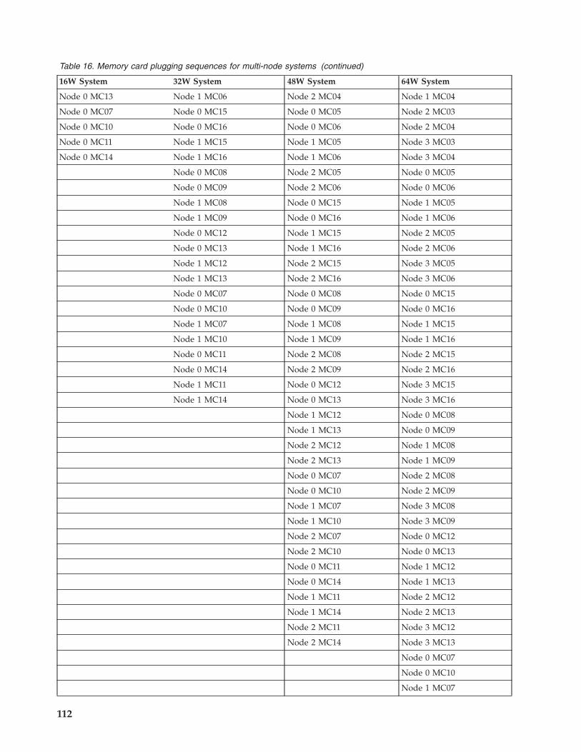
Table 16. Memory card plugging sequences for multi-node systems (continued)
16W System 32W System 48W System 64W System
Node 0 MC13 Node 1 MC06 Node 2 MC04 Node 1 MC04
Node 0 MC07 Node 0 MC15 Node 0 MC05 Node 2 MC03
Node 0 MC10 Node 0 MC16 Node 0 MC06 Node 2 MC04
Node 0 MC11 Node 1 MC15 Node 1 MC05 Node 3 MC03
Node 0 MC14 Node 1 MC16 Node 1 MC06 Node 3 MC04
Node 0 MC08 Node 2 MC05 Node 0 MC05
Node 0 MC09 Node 2 MC06 Node 0 MC06
Node 1 MC08 Node 0 MC15 Node 1 MC05
Node 1 MC09 Node 0 MC16 Node 1 MC06
Node 0 MC12 Node 1 MC15 Node 2 MC05
Node 0 MC13 Node 1 MC16 Node 2 MC06
Node 1 MC12 Node 2 MC15 Node 3 MC05
Node 1 MC13 Node 2 MC16 Node 3 MC06
Node 0 MC07 Node 0 MC08 Node 0 MC15
Node 0 MC10 Node 0 MC09 Node 0 MC16
Node 1 MC07 Node 1 MC08 Node 1 MC15
Node 1 MC10 Node 1 MC09 Node 1 MC16
Node 0 MC11 Node 2 MC08 Node 2 MC15
Node 0 MC14 Node 2 MC09 Node 2 MC16
Node 1 MC11 Node 0 MC12 Node 3 MC15
Node 1 MC14 Node 0 MC13 Node 3 MC16
Node 1 MC12 Node 0 MC08
Node 1 MC13 Node 0 MC09
Node 2 MC12 Node 1 MC08
Node 2 MC13 Node 1 MC09
Node 0 MC07 Node 2 MC08
Node 0 MC10 Node 2 MC09
Node 1 MC07 Node 3 MC08
Node 1 MC10 Node 3 MC09
Node 2 MC07 Node 0 MC12
Node 2 MC10 Node 0 MC13
Node 0 MC11 Node 1 MC12
Node 0 MC14 Node 1 MC13
Node 1 MC11 Node 2 MC12
Node 1 MC14 Node 2 MC13
Node 2 MC11 Node 3 MC12
Node 2 MC14 Node 3 MC13
Node 0 MC07
Node 0 MC10
Node 1 MC07
112

Table 16. Memory card plugging sequences for multi-node systems (continued)
16W System 32W System 48W System 64W System
Node 1 MC10
Node 2 MC07
Node 2 MC10
Node 3 MC07
Node 3 MC10
Node 0 MC11
Node 0 MC14
Node 1 MC11
Node 1 MC14
Node 2 MC11
Node 2 MC14
Node 3 MC11
Node 3 MC14
Reinstall the nodes into the system.After the system has been taken down to the minimum memory for the number of nodes in thesystem, power on the system using the HMC.Does the system boot to server firmware standby with no error codes on the control panel?
NO Go to PFW1546-12.
YES Go to PFW1546-18.v PFW1546-12
The following steps will isolate the failing node. The nodes will be removed, repopulated withmemory, and added back to the system one at a time.Use the HMC to power down the system.Remove all nodes from the system.Reconfigure the memory in the first node according to the first column in the table in PFW1546-11.Reinstall the first node, then use the HMC to power on the system.Does the system boot to server firmware standby with no error codes on the control panel?
NO Go to PFW1546-13.
YES Go to PFW1546-14.v PFW1546-13
The failure has been isolated to the node that was just reinstalled. Do the following in the order listed:1. Use the HMC to power down the system.2. Remove the last node that was reinstalled. Replace the eight memory cards in the node with eight
known-good cards, or eight cards from the ones that were removed in PFW1546-11.3. Reinstall the node.4. Use the HMC to power up the system.Does the system boot to server firmware standby with no error codes on the control panel?
NO Before replacing the node’s backplane and chassis, or one of the MCMs, call the support center.This ends the procedure.
Beginning troubleshooting and problem analysis 113

YES One of the eight memory cards originally in this node is bad. Isolate to the failing quad first,then isolate the failing memory card. Replace the failing card, then go to MAP 0410: RepairCheckout. This ends the procedure.
v PFW1546-14
Use the HMC to power down the system.Is there a second node in the system?
NO Go to PFW1546-17.
YES Do the following:1. Reconfigure the minimum memory in the first node and the second node according to the
second column in the table in PFW1546-11.2. Reinstall the second node, then use the HMC to power on the system.
Does the system boot to server firmware standby with no error codes on the control panel?
NO Go to PFW1546-13.
YES Go to PFW1546-15.v PFW1546-15
Use the HMC to power down the system.Is there a third node in the system?
NO Go to PFW1546-17.
YES Do the following:1. Reconfigure the minimum memory in the first node, the second node, and the third node
according to the second column in the table in PFW1546-11.2. Reinstall the third node, then use the HMC to power on the system.
Does the system boot to server firmware standby with no error codes on the controlpanel?
NO Go to PFW1546-13.
YES Go to PFW1546-16.v PFW1546-16
Use the HMC to power down the system.Is there a fourth node in the system?
NO Go to PFW1546-17.
YES Do the following:1. Reconfigure the minimum memory in the first node, the second node, the third node, and
the fourth node according to the second column in the table in PFW1546-11.2. Reinstall the third node, then use the HMC to power on the system.
Does the system boot to server firmware standby with no error codes on the controlpanel?
NO Go to PFW1546-13.
YES Go to PFW1546-17.v PFW1546-17
The system now boots to server firmware standby with the minimum configuration of memory cards.Go to PFW1546-18 to start adding back in the additional memory in the system.
v PFW1546-18
Power off the system using the HMC.
114

Add another set of four memory cards back in order, one set a time, according to the table inPFW1546-11.After each set of four is added, reinstall the node into the system.Does the system boot to server firmware standby with no error codes on the control panel?
NO Go to PFW1546-20.
YES Go to PFW1546-19.v PFW1546-19
Has the last set of four memory cards been installed (so the system has been returned to its originalconfiguration)?
NO Go to PFW1546-18.
YES The system is now booting to server firmware standby with all of the memory cards installed.Go to MAP 0410: Repair Checkout. This ends the procedure.
v PFW1546-20
The set of four memory cards that was reinstalled in step 18, or the slots into which they wereinstalled, are causing the failure.Do the following:1. Power down the system using the HMC.2. Remove the node into which the last set of memory cards was installed.3. Replace the last set of memory cards that was installed with a known-good set.4. Reinstall the node in the system.5. Using the HMC, power on the system.Does the system boot to server firmware standby with no error codes on the control panel?
NO One or more of the memory slots is bad. Before replacing the chassis, contact the supportcenter. This ends the procedure.
YES Go to PFW1546-21.v PFW1546-21
One or more of the memory cards in the last set installed is bad. Using the known good set, swap outthe memory cards one at a time until the failing card is isolated. Replace it. Return the system to itsoriginal configuration, then go to MAP 0410: Repair Checkout. This ends the procedure.
PFW1548: Memory and processor subsystem problem isolation procedureUse this problem isolation procedure to aid in solving memory and processor problems that are notfound by normal diagnostics.
Notes:
1. To avoid damage to the system or subsystem components, unplug the power cords before removingor installing any part.
2. This procedure assumes that either:v An optical drive is installed and connected to the integrated EIDE adapter, and an AIX diagnostic
CD-ROM is available.OR
v AIX standalone diagnostics can be booted from a NIM server.3. If a power-on password or privileged-access password is set, you are prompted to enter the password
before the AIX diagnostic CD-ROM can load.4. The term POST indicators refers to the device mnemonics that appear during the power-on self-test
(POST).
Beginning troubleshooting and problem analysis 115

5. The service processor might have been set by the user to monitor system operations and to attemptrecoveries. You might want to disable these options while you diagnose and service the system. Ifthese settings are disabled, make notes of their current settings so that they can be restored before thesystem is turned back over to the customer. The following settings may be of interest.
Monitoring(also called surveillance) From the ASMI menu, expand the System Configuration menu, thenclick Monitoring. Disable both types of surveillance.
Auto power restart(also called unattended start mode) From the ASMI menu, expand Power/Restart Control,then click Auto Power Restart, and set it to disabled.
Wake on LANFrom the ASMI menu, expand Wake on LAN, and set it to disabled.
Call OutFrom the ASMI menu, expand the Service Aids menu, then click Call-Home/Call-In Setup.Set the call-home system port and the call-in system port to disabled.
6. Verify that the system has not been set to boot to the System Management Services (SMS) menus or tothe open firmware prompt. From the ASMI menu, expand Power/Restart Control to view the menu,then click Power On/Off System. The AIX/Linux partition mode boot should say ″Continue toOperating System″.
7. The service processor might have recorded one or more symptoms in its error/event log. Use theAdvanced System Management Interface (ASMI) menus to view the error/event log.v If you arrived here after performing a slow boot, look for a possible new error that occurred during
the slow boot. If there is a new error, and its actions call for a FRU replacement, perform thoseactions. If this does not resolve the problem, go to PFW1548-1.
v If an additional slow boot has not been performed, or if the slow boot did not yield a new errorcode, look at the error that occurred just before the original error. Perform the actions associatedwith that error. If this does not resolve the problem, go to PFW1548-1.
v If a slow boot results in the same error code, and there are no error codes before the original errorcode, go to PFW1548-1.
Perform the following procedure:v PFW1548-1
1. Ensure that the diagnostics and the operating system are shut down.Is the system at ″service processor standby″, indicated by 01 in the control panel?
No Replace the system backplane, location: Un-P1. Return to the beginning of this step.
Yes Continue with substep 2.2. Turn on the power using either the white button or the ASMI menus.
If an HMC is attached, does the system reach hypervisor standby as indicated on the HMC? Ifan HMC is not attached, does the system reach an operating system login prompt, or if bootingthe AIX standalone diagnostic CD-ROM, is the �Please define the System Console� screendisplayed?
No Go to PFW1548-3.
Yes Go to PFW1548-2.3. Insert the AIX standalone diagnostic CD-ROM into the optical drive.
Note: If you cannot insert the diagnostic CD-ROM, go to PFW1548-2.4. When the word keyboard is displayed on an ASCII terminal, a directly attached keyboard, or
hardware management console (HMC), press the number 5 key.5. If you are prompted to do so, enter the appropriate password.
116

Is the ″Please define the System Console″ screen displayed?
No Go to PFW1548-2.
Yes Go to PFW1548-14.v PFW1548-2
Insert the AIX standalone diagnostic CD-ROM into the optical drive.
Note: If you cannot insert the AIX standalone diagnostic CD-ROM, go to step PFW1548-3.Turn on the power using either the white button or the ASMI menus. (If the AIX standalone diagnosticCD-ROM is not in the optical drive, insert it now.) If an HMC is attached, after the system has reachedhypervisor standby, activate a Linux or AIX partition by clicking the Advanced button on theactivation screen. On the Advanced activation screen, select Boot in service mode using the defaultboot list to boot the AIX standalone diagnostic CD-ROM.If you are prompted to do so, enter the appropriate password.Is the ″Please define the System Console″ screen displayed?
No Go to PFW1548-3.
Yes Go to PFW1548-14.v PFW1548-3
1. Turn off the power.2. If you have not already done so, configure the service processor (using the ASMI menus) with the
instructions in note 6 at the beginning of this procedure, then return here and continue.3. Exit the service processor (ASMI) menus and remove the power cords.4. Disconnect all external cables (parallel, system port 1, system port 2, keyboard, mouse, USB devices,
SPCN, Ethernet on the system planar, and so on). Also disconnect all of the external cables attachedto the service processor except the Ethernet cable going to the HMC, if an HMC is attached.
5. Is the system an 8234-EMA, 9117-MMA, or 9406-MMA and is there more than one processor drawerin the system?
No: Go to PFW1548-4.
Yes: Go to PFW1548-3.1 .
Go to the next step.v PFW1548-3.1
Disconnect the flex cables from the front and the back of all the processor drawers if not alreadydisconnected. Does the processor drawer with the service processor card power on OK?
No: Go to the next step.
Yes Go to PFW1548-13.2v PFW1548-4
Using the following table, locate the system machine type and model you are servicing and determinethe action to perform.
Beginning troubleshooting and problem analysis 117
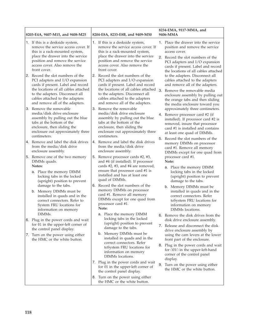
8203-E4A, 9407-M15, and 9408-M25 8204-E8A, 8233-E8B, and 9409-M508234-EMA, 9117-MMA, and9406-MMA
1. If this is a deskside system,remove the service access cover. Ifthis is a rack-mounted system,place the drawer into the serviceposition and remove the serviceaccess cover. Also remove thefront cover.
2. Record the slot numbers of thePCI adapters and I/O expansioncards if present. Label and recordthe locations of all cables attachedto the adapters. Disconnect allcables attached to the adaptersand remove all of the adapters.
3. Remove the removablemedia/disk drive enclosureassembly by pulling out the bluetabs at the bottom of theenclosure, then sliding theenclosure out approximately threecentimeters.
4. Remove and label the disk drivesfrom the media/disk driveenclosure assembly.
5. Remove one of the two memoryDIMMs quads.Notes:
a. Place the memory DIMMlocking tabs in the locked(upright) position to preventdamage to the tabs.
b. Memory DIMMs must beinstalled in quads and in thecorrect connectors. Refer toSystem FRU locations forinformation on memoryDIMMs.
6. Plug in the power cords and waitfor 01 in the upper-left corner ofthe control panel display.
7. Turn on the power using eitherthe HMC or the white button.
1. If this is a deskside system,remove the service access cover. Ifthis is a rack-mounted system,place the drawer into the serviceposition and remove the serviceaccess cover. Also remove thefront cover.
2. Record the slot numbers of thePCI adapters and I/O expansioncards if present. Label and recordthe locations of all cables attachedto the adapters. Disconnect allcables attached to the adaptersand remove all of the adapters.
3. Remove the removablemedia/disk drive enclosureassembly by pulling out the bluetabs at the bottom of theenclosure, then sliding theenclosure out approximately threecentimeters.
4. Remove and label the disk drivesfrom the media/disk driveenclosure assembly.
5. Remove processor cards #2, #3,and #4 (if installed). If processorcards #2, #3, and #4 are removed,ensure that processor card #1 isinstalled and has at least onequad of DIMMs.
6. Record the slot numbers of thememory DIMMs on processorcard #1. Remove all memoryDIMMs except for one quad fromprocessor card #1.Note:
a. Place the memory DIMMlocking tabs in the locked(upright) position to preventdamage to the tabs.
b. Memory DIMMs must beinstalled in quads and in thecorrect connectors. RefertoSystem FRU locations forinformation on memoryDIMMs locations.
7. Plug in the power cords and waitfor 01 in the upper-left corner ofthe control panel display.
8. Turn on the power using eitherthe HMC or the white button.
1. Place the drawer into the serviceposition and remove the serviceaccess cover.
2. Record the slot numbers of thePCI adapters and I/O expansioncards if present. Label and recordthe locations of all cables attachedto the adapters. Disconnect allcables attached to the adaptersand remove all of the adapters.
3. Remove the removable mediaenclosure assembly by pulling outthe orange tabs and then slidingthe media enclosure toward youapproximately three centimeters.
4. Remove processor card #2 (ifinstalled). If processor card #2 isremoved, insure that processorcard #1 is installed and containsat least one quad of DIMMs.
5. Record the slot numbers of thememory DIMMs on processorcard #1. Remove all memoryDIMMs except for one quad fromprocessor card #1.Note:
a. Place the memory DIMMlocking tabs in the locked(upright) position to preventdamage to the tabs.
b. Memory DIMMs must beinstalled in quads and in thecorrect connectors. RefertoSystem FRU locations forinformation on memoryDIMMs locations.
6. Remove the disk drives from thedisk drive enclosure assembly.
7. Release and disconnect the diskdrive enclosure assembly byusing the cam levers at the lowerfront part of the enclosure.
8. Plug in the power cords and waitfor �01� in the upper-left-handcorner of the control paneldisplay.
9. Turn on the power using eitherthe HMC or the white button.
118

If an HMC is attached, does the managed system reach power on at hypervisor standby as indicatedon the HMC? If an HMC is not attached, does the system reach an operating system login prompt,or if booting the AIX standalone diagnostic CD-ROM, is the �Please define the System Console�screen displayed?
No Go to PFW1548-7.
Yes Go to the next step.v PFW1548-5
For 8203-E4A, 9407-M15, and 9408-M25, were any memory DIMMs removed from systembackplane?For 8234-EMA, 9117-MMA, and 9406-MMA were any memory DIMMs removed from processorcard #1?
No Go to PFW1548-8.
Yes Go to the next step.v PFW1548-6
1. Turn off the power, and remove the power cords.2. For 8203-E4A, 9407-M15, and 9408-M25, replug the memory DIMMs that were removed from
system backplane in PFW1548-2 in their original locations. For 8204–E8A and 9409-M50, 8234-EMA,9117-MMA, or 9406-MMA, replug the memory DIMMs that were removed from processor card #1in PFW1548-2 in their original locations.
Notes:
a. Place the memory DIMM locking tabs into the locked (upright) position to prevent damage tothe tabs.
b. Memory DIMMs must be installed in quads in the correct connectors. Refer to System FRUlocations for information on memory DIMMs locations for the system that you are servicing.
3. Plug in the power cords and wait for 01 in the upper-left corner of the control panel display.4. Turn on the power using either the HMC or the white button.
If an HMC is attached, does the managed system reach power on at hypervisor standby asindicated on the HMC? If an HMC is not attached, does the system reach an operating systemlogin prompt, or if booting the AIX diagnostic CD-ROM, is the �Please define the SystemConsole� screen displayed?
No: Using the following table, locate the system machine type and model you are servicing anddetermine the action to perform.
Beginning troubleshooting and problem analysis 119
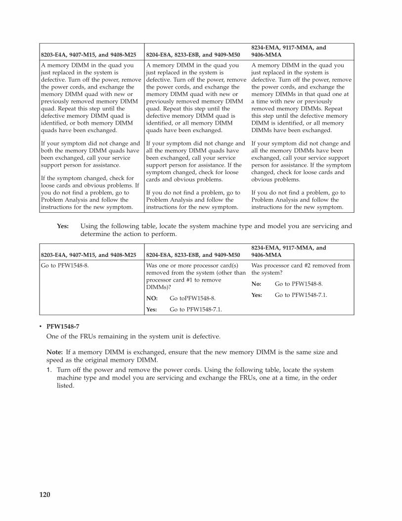
8203-E4A, 9407-M15, and 9408-M25 8204-E8A, 8233-E8B, and 9409-M508234-EMA, 9117-MMA, and9406-MMA
A memory DIMM in the quad youjust replaced in the system isdefective. Turn off the power, removethe power cords, and exchange thememory DIMM quad with new orpreviously removed memory DIMMquad. Repeat this step until thedefective memory DIMM quad isidentified, or both memory DIMMquads have been exchanged.
If your symptom did not change andboth the memory DIMM quads havebeen exchanged, call your servicesupport person for assistance.
If the symptom changed, check forloose cards and obvious problems. Ifyou do not find a problem, go toProblem Analysis and follow theinstructions for the new symptom.
A memory DIMM in the quad youjust replaced in the system isdefective. Turn off the power, removethe power cords, and exchange thememory DIMM quad with new orpreviously removed memory DIMMquad. Repeat this step until thedefective memory DIMM quad isidentified, or all memory DIMMquads have been exchanged.
If your symptom did not change andall the memory DIMM quads havebeen exchanged, call your servicesupport person for assistance. If thesymptom changed, check for loosecards and obvious problems.
If you do not find a problem, go toProblem Analysis and follow theinstructions for the new symptom.
A memory DIMM in the quad youjust replaced in the system isdefective. Turn off the power, removethe power cords, and exchange thememory DIMMs in that quad one ata time with new or previouslyremoved memory DIMMs. Repeatthis step until the defective memoryDIMM is identified, or all memoryDIMMs have been exchanged.
If your symptom did not change andall the memory DIMMs have beenexchanged, call your service supportperson for assistance. If the symptomchanged, check for loose cards andobvious problems.
If you do not find a problem, go toProblem Analysis and follow theinstructions for the new symptom.
Yes: Using the following table, locate the system machine type and model you are servicing anddetermine the action to perform.
8203-E4A, 9407-M15, and 9408-M25 8204-E8A, 8233-E8B, and 9409-M508234-EMA, 9117-MMA, and9406-MMA
Go to PFW1548-8. Was one or more processor card(s)removed from the system (other thanprocessor card #1 to removeDIMMs)?
NO: Go toPFW1548-8.
Yes: Go to PFW1548-7.1.
Was processor card #2 removed fromthe system?
No: Go to PFW1548-8.
Yes: Go to PFW1548-7.1.
v PFW1548-7
One of the FRUs remaining in the system unit is defective.
Note: If a memory DIMM is exchanged, ensure that the new memory DIMM is the same size andspeed as the original memory DIMM.1. Turn off the power and remove the power cords. Using the following table, locate the system
machine type and model you are servicing and exchange the FRUs, one at a time, in the orderlisted.
120

8203-E4A, 9407-M15, and 9408-M25 8204-E8A, 8233-E8B, and 9409-M508234-EMA, 9117-MMA, and9406-MMA
1. Memory DIMMs. Exchange onequad at a time with new orpreviously removed DIMM quads
2. System backplane, location: Un-P1
3. Power supplies, locations: Un-E1and Un-E2.
1. Memory DIMMs. Exchange onequad at a time with new orpreviously removed DIMM quads
2. Processor card #1, location:Un-P1-C13.
3. System backplane, location: Un-P1
4. Power supplies, locations: Un-E1and Un-E2.
1. Memory DIMMs. Exchange one ata time with new or previouslyremoved DIMMs
2. Processor card #1, location:Un-P2-C1.
3. Processor backplane, location:Un-P2
4. Power supplies, locations: Un-E1and Un-E2.
5. Processor regulators, locations:Un-P2-C3, Un-P2-C4, Un-P2-C5.
6. Service processor, location:Un-P1-C11.
7. I/O backplane, location: Un-P1.
2. Plug in the power cords and wait for 01 in the upper-left corner of the control panel display.3. Turn on the power using either the HMC or the white button.If an HMC is attached, does the managed system reach power on at hypervisor standby as indicatedon the HMC? If an HMC is not attached, does the system reach an operating system login prompt,or if booting the AIX diagnostic CD-ROM, is the �Please define the System Console� screendisplayed?
No Reinstall the original FRU.
Repeat the FRU replacement steps until the defective FRU is identified or all the FRUs havebeen exchanged.
If the symptom did not change and all the FRUs have been exchanged, call service support forassistance.
If the symptom has changed, check for loose cards, cables, and obvious problems. If you donot find a problem, go to Problem Analysis and follow the instructions for the new symptom.
Yes Go to Verify a repair.v PFW1548-7.1
Using the following table, locate the system machine type and model you are servicing and determinethe action to perform.
Beginning troubleshooting and problem analysis 121

8204-E8A, 8233-E8B, and 9409-M50 8234-EMA, 9117-MMA, and 9406-MMA
No failure was detected with this configuration.
1. Turn off the power and remove the power cords.
2. Reinstall the next processor card.
3. Plug in the power cords and wait for 01 in theupper-left corner of the control panel display.
4. Turn on the power using either the HMC or thewhite button.
If an HMC is attached, does the managed systemreach power on at hypervisor standby as indicatedon the HMC? If an HMC is not attached, does thesystem reach an operating system login prompt, orif booting the AIX diagnostic CD-ROM, is the�Please define the System Console� screendisplayed?
NO: One of the FRUs remaining in the system isdefective. Exchange the FRUs (that have notalready been changed) in the followingorder:
a. Memory DIMMs (if present) on processorcard that was just reinstalled. Exchangethe DIMM quads one at a time with newor previously removed DIMM quads.
b. The processor card that was justreinstalled.
c. System backplane, location: Un-P1.
d. Power supplies, locations: Un-E1 andUn-E2.
Repeat the FRU replacement steps untilthe defective FRU is identified or all theFRUs have been exchanged.
If the symptom did not change and allthe FRUs have been exchanged, callservice support for assistance.
If the symptom has changed, check forloose cards, cables, and obviousproblems. If you do not find a problem,go to Problem Analysis and follow theinstructions for the new symptom.
Yes: If all of the processor cards been reinstalled,go to the next step. Otherwise, repeat thisstep.
No failure was detected with this configuration.
1. Turn off the power and remove the power cords.
2. Reinstall processor card #2.
3. Plug in the power cords and wait for �01� in theupper-left corner of the control panel display.
4. Turn on the power using either the HMC or thewhite button.
If an HMC is attached, does the managed systemreach power on at hypervisor standby as indicatedon the HMC? If an HMC is not attached, does thesystem reach an operating system login prompt, orif booting the AIX diagnostic CD-ROM, is the�Please define the System Console� screendisplayed?
NO: One of the FRUs remaining in the system isdefective. Exchange the FRUs (that have notalready been changed) in the followingorder:
a. Memory DIMMs (if present) on processorcard #2. Exchange the DIMMs one at atime with new or previously removedDIMMs.
b. Processor card #2
c. Processor backplane, location: Un-P2.
d. Power supplies, locations: Un-E1 andUn-E2.
e. Processor regulators, locations: Un-P2-C3,Un-P2-C4, Un-P2-C5.
f. Service processor, location: Un-P1-C11.
g. I/O backplane, location: Un-P1.
Repeat the FRU replacement steps until thedefective FRU is identified or all the FRUshave been exchanged.
If the symptom did not change and all theFRUs have been exchanged, call servicesupport for assistance.
If the symptom has changed, check for loosecards, cables, and obvious problems. If youdo not find a problem, go to ProblemAnalysis and follow the instructions for thenew symptom.
YES Go to the next step.
v PFW1548-8
1. Turn off the power.2. Reconnect the system console.
Notes:
a. If an ASCII terminal has been defined as the firmware console, attach the ASCII terminal cableto the S1 connector on the rear of the system unit.
122

b. If a display attached to a display adapter has been defined as the firmware console, install thedisplay adapter and connect the display to the adapter. Plug the keyboard and mouse into thekeyboard connector on the rear of the system unit.
3. Turn on the power using either the HMC or the white button. (If the AIX standalone diagnosticCD-ROM is not in the optical drive, insert it now.) If an HMC is attached, after the system hasreached hypervisor standby, activate a Linux or AIX partition by clicking the Advanced button onthe activation screen. On the Advanced activation screen, select Boot in service mode using thedefault boot list to boot the AIX standalone diagnostic CD-ROM.
4. If the ASCII terminal or graphics display (including display adapter) is connected differently fromthe way it was previously, the console selection screen appears. Select a firmware console.
5. Immediately after the word keyboard is displayed, press the number 1 key on the directly attachedkeyboard, an ASCII terminal or HMC. This activates the system management services (SMS).
6. Enter the appropriate password if you are prompted to do so.Is the SMS screen displayed?
No One of the FRUs remaining in the system unit is defective.
Exchange the FRUs that have not been exchanged, in the following order:1. If you are using an ASCII terminal, go to the problem determination procedures for the
display. If you do not find a problem, do the following:
8203-E4A, 9407-M15, 9408-M25, 8204-E8A, 8233-E8B, and9409-M50 8234-EMA, 9117-MMA, and 9406-MMA
Replace the system backplane, location: Un-P1. 1. Replace the service processor, location: Un-P1-C11.
2. Replace the I/O backplane, location: Un-P1.
2. If you are using a graphics display, go to the problem determination procedures for thedisplay. If you do not find a problem, do the following:a. Replace the display adapter.b. Replace the backplane in which the graphics adapter is plugged.
Repeat this step until the defective FRU is identified or all the FRUs have beenexchanged.If the symptom did not change and all the FRUs have been exchanged, call servicesupport for assistance.If the symptom changed, check for loose cards, cables, and obvious problems. If you donot find a problem, go to Problem Analysis and follow the instructions for the newsymptom.
Yes Go to the next step.v PFW1548-9
1. Make sure the AIX standalone diagnostic CD-ROM is inserted into the optical drive.2. Turn off the power and remove the power cords.3. Use the cam levers to reconnect the disk drive enclosure assembly to the I/O backplane.4. Using the following table, locate the system machine type and model you are servicing and
determine the action to perform.
8203-E4A, 9407-M15, 9408-M25 8204-E8A, 8233-E8B, and9409-M50 8234-EMA, 9117-MMA, and 9406-MMA
Reconnect the removable media/disk drive enclosureassembly by sliding the media enclosure toward the rearof the system, then pressing the blue tabs.
Reconnect the removable media enclosure assembly bysliding the media enclosure toward the disk drivebackplane and then pressing the orange tabs.
5. Plug in the power cords and wait for 01 in the upper-left corner of the operator panel display.
Beginning troubleshooting and problem analysis 123

6. Turn on the power using either the HMC or the white button. (If the AIX standalone diagnosticCD-ROM is not in the optical drive, insert it now.) If an HMC is attached, after the system hasreached hypervisor standby, activate a Linux or AIX partition by clicking the Advanced button onthe activation screen. On the Advanced activation screen, select Boot in service mode using thedefault boot list to boot the AIX standalone diagnostic CD-ROM.
7. Immediately after the word keyboard is displayed, press the number 5 key on either the directlyattached keyboard or an ASCII terminal keyboard.
8. Enter the appropriate password if you are prompted to do so.Is the ″Please define the System Console″ screen displayed?
No: One of the FRUs remaining in the system unit is defective.
Using the following table, locate the system machine type and model you are servicing andexchange the FRUs in the order listed that have not been exchanged.
8203-E4A, 9407-M15, 9408-M25 8204-E8A, 8233-E8B, and9409-M50 8234-EMA, 9117-MMA, and 9406-MMA
1. Optical drive
2. Removable media enclosure.
3. System backplane, Un-P1.
1. Optical drive
2. Removable media enclosure.
3. Disk drive enclosure (no disk drives at this time)
4. I/O backplane, Un-P1.
Repeat this step until the defective FRU is identified or all the FRUs have been exchanged.
If the symptom did not change and all the FRUs have been exchanged, call service support forassistance.
If the symptom has changed, check for loose cards, cables, and obvious problems. If you donot find a problem, go to Problem Analysis and follow the instructions for the new symptom.
Yes: Go to the next step.v PFW1548-10
The system is working correctly with this configuration. One of the disk drives that you removed fromthe disk drive backplanes may be defective.1. Make sure the AIX standalone diagnostic CD-ROM is inserted into the optical drive.2. Turn off the power and remove the power cords.3. Using the following table, locate the system machine type and model you are servicing and
determine the action to perform.
8203-E4A, 9407-M15, 9408-M25, 8204-E8A, 8233-E8B, and9409-M50 8234-EMA, 9117-MMA, and 9406-MMA
Install a disk drive in the media/disk drive enclosureassembly.
Install a disk drive in the disk drive enclosure assembly.
4. Plug in the power cords and wait for the OK prompt to display on the operator panel display.5. Turn on the power.6. Immediately after the word keyboard is displayed, press the number 5 key on either the directly
attached keyboard or an ASCII terminal keyboard.7. Enter the appropriate password if you are prompted to do so.Is the ″Please define the System Console″ screen displayed?
No Using the following table, locate the system machine type and model you are servicing andexchange the FRUs in the order listed that have not been exchanged.
124

8203-E4A, 9407-M15, 9408-M25, 8204-E8A, 8233-E8B, and9409-M50 8234-EMA, 9117-MMA, and 9406-MMA
1. Last disk drive installed
2. Disk drive backplane.
1. Last disk drive installed
2. Disk drive enclosure assembly.
Repeat this step until the defective FRU is identified or all the FRUs have been exchanged.
If the symptom did not change and all the FRUs have been exchanged, call service support forassistance.
If the symptom has changed, check for loose cards, cables, and obvious problems. If you donot find a problem, go to Problem Analysis and follow the instructions for the new symptom.
Yes Repeat this step with all disk drives that were installed in the disk drive backplane.
After all of the disk drives have been reinstalled, go to the next step.v PFW1548-11
The system is working correctly with this configuration. One of the devices that was disconnected fromthe system backplane may be defective.1. Turn off the power and remove the power cords.2. Attach a system backplane device (for example: system port 1, system port 2, USB, keyboard,
mouse, Ethernet) that had been removed.After all of the I/O backplane device cables have been reattached, reattached the cables to theservice processor one at a time.
3. Plug in the power cords and wait for 01 in the upper-left corner on the operator panel display.4. Turn on the power using either the HMC or the white button. (If the AIX standalone diagnostic
CD-ROM is not in the optical drive, insert it now.) If an HMC is attached, after the system hasreached hypervisor standby, activate a Linux or AIX partition by clicking the Advanced button onthe activation screen. On the Advanced activation screen, select Boot in service mode using thedefault boot list to boot the AIX standalone diagnostic CD-ROM.
5. If the Console Selection screen is displayed, choose the system console.6. Immediately after the word keyboard is displayed, press the number 5 key on either the directly
attached keyboard or on an ASCII terminal keyboard.7. Enter the appropriate password if you are prompted to do so.Is the ″Please define the System Console″ screen displayed?
No The last device or cable that you attached is defective.
To test each FRU, use the following table to locate the system machine type and model you areservicing, then exchange the FRUs in the order listed.
8203-E4A, 9407-M15, 9408-M25, 8204-E8A, 8233-E8B, and9409-M50 8234-EMA, 9117-MMA, and 9406-MMA
1. Device and cable (last one attached)
2. System backplane, location: Un-P1.
1. Device and cable (last one attached)
2. If the last cable in this step was reconnected to theservice processor, replace the service processor.
3. I/O backplane, location: Un-P1.
If the symptom did not change and all the FRUs have been exchanged, call service support forassistance.
If the symptom has changed, check for loose cards, cables, and obvious problems. If you donot find a problem, go to Problem Analysis and follow the instructions for the new symptom.
Yes Repeat this step until all of the devices are attached. Go to the next step.
Beginning troubleshooting and problem analysis 125

v PFW1548-12
The system is working correctly with this configuration. One of the FRUs (adapters) that you removedmay be defective.1. Turn off the power and remove the power cords.2. Install a FRU (adapter) and connect any cables and devices that were attached to the FRU.3. Plug in the power cords and wait for the OK prompt to display on the operator panel display.4. Turn on the power using either the HMC or the white button. (If the AIX standalone diagnostic
CD-ROM is not in the optical drive, insert it now.) If an HMC is attached, after the system hasreached hypervisor standby, activate a Linux or AIX partition by clicking the Advanced button onthe activation screen. On the Advanced activation screen, select Boot in service mode using thedefault boot list to boot the AIX standalone diagnostic CD-ROM.
5. If the Console Selection screen is displayed, choose the system console.6. Immediately after the word keyboard is displayed, press the number 5 key on either the directly
attached keyboard or on an ASCII terminal keyboard.7. Enter the appropriate password if you are prompted to do so.Is the ″Please define the System Console″ screen displayed?
No Go to the next step.
Yes Repeat this step until all of the FRUs (adapters) are installed. Go to Verify a repair.v PFW1548-13
The last FRU installed or one of its attached devices is probably defective.1. Make sure the AIX standalone diagnostic CD-ROM is inserted into the optical drive.2. Turn off the power and remove the power cords.3. Starting with the last installed adapter, disconnect one attached device and cable.4. Plug in the power cords and wait for the 01 in the upper-left corner on the operator panel display.5. Turn on the power using either the HMC or the white button. (If the AIX standalone diagnostic
CD-ROM is not in the optical drive, insert it now.) If an HMC is attached, after the system hasreached hypervisor standby, activate a Linux or AIX partition by clicking the Advanced button onthe Advanced activation screen. On the Advanced activation screen, select Boot in service modeusing the default boot list to boot the AIX standalone diagnostic CD-ROM.
6. If the Console Selection screen is displayed, choose the system console.7. Immediately after the word keyboard is displayed, press the number 5 key on either the directly
attached keyboard or on an ASCII terminal keyboard.8. Enter the appropriate password if you are prompted to do so.Is the ″Please define the System Console″ screen displayed?
No Repeat this step until the defective device or cable is identified or all devices and cables havebeen disconnected.
If all the devices and cables have been removed, then one of the FRUs remaining in the systemunit is defective.
To test each FRU, use the following table to locate the system machine type and model you areservicing, then exchange the FRUs in the order listed.
8203-E4A, 9407-M15, 9408-M25, 8204-E8A, 8233-E8B, and9409-M50 8234-EMA, 9117-MMA, and 9406-MMA
1. Adapter (last one installed)
2. System backplane, location: Un-P1.
1. Adapter (last one installed)
2. I/O backplane, location: Un-P1.
If the symptom did not change and all the FRUs have been exchanged, call service support forassistance.
126
If the symptom has changed, check for loose cards, cables, and obvious problems. If you donot find a problem, go to the Problem Analysis and follow the instructions for the newsymptom.
Yes The last device or cable that you disconnected is defective. Exchange the defective device orcable then go to the next step.
v PFW1548-13.1
Is the system an 8234-EMA, 9117-MMA, or 9406-MMA?
No: Go to PFW1548-14.
Yes: Go to the next step.v PFW1548-13.2
Reattach the flex cables, if present, both front and back. Return the system to its original configuration.Reinstall the control panel, the VPC card, and the service processor in the original primary processordrawer. Reattach the power cords and power on the system.Does the system come up properly?
NO: Go to the next step.
Yes: Go to Verify a repair..v PFW1548-13.3
Have all of the drawers been tested individually with the physical control panel (if present), serviceprocessor, and VPD card?
No:
1. Detach the flex cables from the front and back of the system if not already disconnected.2. Remove the service processor card, the VPD card, and the control panel from the processor
drawer that was just tested.3. Install these parts in the next drawer in the rack, going top to bottom.4. Go to PFW1548-3.
YES: Reinstall the control panel, the VPD card, and the service processor card in the originalprimary processor drawer. Return the system to its original configuration. Suspect a problemwith the flex cables. If the error code indicates a problem with the SPCN or service processorcommunication between drawers, replace the flex cable in the rear. If the error code indicates aproblem with inter-processor drawer communication, replace the flex cable on the front of thesystem. Continue with the next step.
v PFW1548-13.4
Did replacing the flex cable(s) resolve the problem?
NO: Go to step the next step.
Yes: The problem is resolved. Go to Verify a repair.v PFW1548-13.5
Replacing the flex cables did not resolve the problem. If the problem appears to be with the serviceprocessor or SPCN signals, suspect the I/O backplanes. If the problem appears to be with processorcommunication, suspect the processor cards. Replace the I/O backplanes, or processor cards, one at atime until the defective part is found.Did this resolve the problem?
NO: Contact your next level of support.
Yes: The problem is resolved. Go to Verify a repair.v PFW1548-14
1. Follow the instructions on the screen to select the system console.2. When the DIAGNOSTIC OPERATING INSTRUCTIONS screen is displayed, press Enter.
Beginning troubleshooting and problem analysis 127

3. Select Advanced Diagnostics Routines.4. If the terminal type has not been defined, you must use the option Initialize Terminal on the
FUNCTION SELECTION menu to initialize the AIX diagnostic environment before you cancontinue with the diagnostics. This is a separate operation from selecting the console display.
5. If the NEW RESOURCE screen is displayed, select an option from the bottom of the screen.
Note: Adapters and devices that require supplemental media are not shown in the new resourcelist. If the system has adapters or devices that require supplemental media, select option 1.
6. When the DIAGNOSTIC MODE SELECTION screen is displayed, press Enter.7. Select All Resources. (If you were sent here from step PFW1548-18, select the adapter or device that
was loaded from the supplemental media).Did you get an SRN?
No Go to step PFW1548-16.
Yes Go to the next step.v PFW1548-15
Look at the FRU part numbers associated with the SRN.Have you exchanged all the FRUs that correspond to the failing function codes (FFCs)?
No Exchange the FRU with the highest failure percentage that has not been changed.
Repeat this step until all the FRUs associated with the SRN have been exchanged ordiagnostics run with no trouble found. Run diagnostics after each FRU is exchanged. Go toVerify a repair.
Yes If the symptom did not change and all the FRUs have been exchanged, call service support forassistance.
v PFW1548-16
Does the system have adapters or devices that require supplemental media?
No Go to step the next step.
Yes Go to step PFW1548-18.v PFW1548-17
Consult the PCI adapter configuration documentation for your operating system to verify that alladapters are configured correctly.Go to Verify a repair.If the symptom did not change and all the FRUs have been exchanged, call service support forassistance.
v PFW1548-18
1. Select Task Selection.2. Select Process Supplemental Media and follow the on-screen instructions to process the media.
Supplemental media must be loaded and processed one at a time.Did the system return to the TASKS SELECTION SCREEN after the supplemental media wasprocessed?
No Go to the next step.
Yes Press F3 to return to the FUNCTION SELECTION screen. Go to step PFW1548-14
substep 4.v PFW1548-19
The adapter or device is probably defective.If the supplemental media is for an adapter, replace the FRUs in the following order:
128

1. Adapter2. System backplane, location: Un-P1.If the supplemental media is for a device, replace the FRUs in the following order:
8203-E4A, 9407-M15, 9408-M25, 8204-E8A, 8233-E8B, and9409-M50 8234-EMA, 9117-MMA, and 9406-MMA
1. Device and any associated cables
2. The adapter to which the device is attached
1. Adapter
2. I/O backplane, location: UN-P1.
Repeat this step until the defective FRU is identified or all the FRUs have been exchanged.If the symptom did not change and all the FRUs have been exchanged, call service support forassistance.If the symptom has changed, check for loose cards, cables, and obvious problems. If you do not find aproblem, go to Problem Analysis and follow the instructions for the new symptom.Go to Verify a repair.End of procedure.
PFW1548: Memory and processor subsystem problem isolation procedure when an HMC is attached:This procedure is used to locate defective FRUs not found by normal diagnostics. For this procedure,diagnostics are run on a minimally configured system. If a failure is detected on the minimallyconfigured system, the remaining FRUs are exchanged one at a time until the failing FRU is identified. Ifa failure is not detected, FRUs are added back until the failure occurs. The failure is then isolated to thefailing FRU.
Note: the system backplane has two memory DIMM quads: Un-P1-C14 to Un-P1-C17, and Un-P1-C21 toUn-P1-C24. See System FRU locations for information on system FRU locations.
Perform the following procedure:v PFW1548-1
1. Ensure that the diagnostics and the operating system are shut down.Is the system at ″service processor standby″, indicated by 01 in the control panel?
No Replace the system backplane, location: Un-P1. Return to step PFW1548-1.
Yes Continue with substep 2.2. Turn on the power using either the white button or the ASMI menus.
Does the system reach hypervisor standby as indicated on the HMC?
No Go to PFW1548-3.
Yes Go to PFW1548-2.3. Insert the AIX diagnostic CD-ROM into the optical drive.
Note: If you cannot insert the diagnostic CD-ROM, go to PFW1548-2.4. When the word keyboard is displayed on an ASCII terminal, a directly attached keyboard, or
hardware management console (HMC), press the number 5 key.5. If you are prompted to do so, enter the appropriate password.
Is the ″Please define the System Console″ screen displayed?
No Go to PFW1548-2.
Yes Go to PFW1548-14.v PFW1548-2
Insert the AIX diagnostic CD-ROM into the optical drive.
Beginning troubleshooting and problem analysis 129

Note: If you cannot insert the diagnostic CD-ROM, go to step PFW1548-3.Turn on the power using either the white button or the ASMI menus. (If the diagnostic CD-ROM is notin the optical drive, insert it now.) After the system has reached hypervisor standby, activate a Linux orAIX partition by clicking the Advanced button on the activation screen. On the Advanced activationscreen, select Boot in service mode using the default boot list to boot the diagnostic CD-ROM.If you are prompted to do so, enter the appropriate password.Is the ″Please define the System Console″ screen displayed?
No Go to PFW1548-3.
Yes Go to PFW1548-14.v PFW1548-3
1. Turn off the power.2. If you have not already done so, configure the service processor (using the ASMI menus), follow
the instructions in note 6 located in “PFW1548: Memory and processor subsystem problem isolationprocedure” on page 115 and then return here and continue.
3. Exit the service processor (ASMI) menus and remove the power cords.4. Disconnect all external cables (parallel, system port 1, system port 2, keyboard, mouse, USB devices,
SPCN, Ethernet on the system planar, and so on). Also disconnect all of the external cables attachedto the service processor except the Ethernet cable going to the HMC.
Go to the next step.v PFW1548-4
1. If this is a deskside system, remove the service access cover. If this is a rack-mounted system, placethe drawer into the service position and remove the service access cover. Also remove the frontcover.
2. Record the slot numbers of the PCI adapters and I/O expansion cards if present. Label and recordthe locations of all cables attached to the adapters. Disconnect all cables attached to the adaptersand remove all of the adapters.
3. Remove the removable media/disk drive enclosure assembly by pulling out the blue tabs at thebottom of the enclosure, then sliding the enclosure out approximately three centimeters.
4. Remove and label the disk drives from the media/disk drive enclosure assembly.5. Remove one of the two memory DIMMs quads.
Notes:
a. Place the memory DIMM locking tabs in the locked (upright) position to prevent damage to thetabs.
b. Memory DIMMs must be installed in quads and in the correct connectors. Refer to System FRUlocations for information on memory DIMMs locations.
6. Plug in the power cords and wait for 01 in the upper-left corner of the control panel display.7. Turn on the power using either the HMC or the white button.Does the managed system reach power on at hypervisor standby as indicated on the HMC?
No Go to PFW1548-7.
Yes Go to the next step.v PFW1548-5
Were any memory DIMMs removed from system backplane?
No Go to PFW1548-8.
Yes Go to the next step.v PFW1548-6
1. Turn off the power, and remove the power cords.
130

2. Replug the memory DIMMs that were removed from system backplane in PFW1548-2 in theiroriginal locations.
Notes:
a. Place the memory DIMM locking tabs into the locked (upright) position to prevent damage tothe tabs.
b. Memory DIMMs must be installed in quads in the correct connectors. Refer to System FRUlocations for information on memory DIMM locations..
3. Plug in the power cords and wait for 01 in the upper-left corner of the control panel display.4. Turn on the power using either the HMC or the white button.Does the managed system reach power on at hypervisor standby as indicated on the HMC?
No A memory DIMM in the quad you just replaced in the system is defective. Turn off the power,remove the power cords, and exchange the memory DIMM quad with new or previouslyremoved memory DIMM quad. Repeat this step until the defective memory DIMM quad isidentified, or both memory DIMM quads have been exchanged.
Note: the system backplane has two memory DIMM quads: Un-P1-C1x-C1 to Un-P1-C1x-C4,and Un-P1-C1x-C6 to Un-P1-C1x-C9. See System FRU locations.
If your symptom did not change and both the memory DIMM quads have been exchanged,call your service support person for assistance.
If the symptom changed, check for loose cards and obvious problems. If you do not find aproblem, go to the Problem Analysis procedures and follow the instructions for the newsymptom.
Yes Go to the next step.v PFW1548-7
One of the FRUs remaining in the system unit is defective.
Note: If a memory DIMM is exchanged, ensure that the new memory DIMM is the same size andspeed as the original memory DIMM.1. Turn off the power, remove the power cords, and exchange the following FRUs, one at a time, in
the order listed:a. Memory DIMMs. Exchange one quad at a time with new or previously removed DIMM quadsb. System backplane, location: Un-P1c. Power supplies, locations: Un-E1 and Un-E2.
2. Plug in the power cords and wait for 01 in the upper-left corner of the control panel display.3. Turn on the power using either the HMC or the white button.Does the managed system reach power on at hypervisor standby as indicated on the HMC?
No Reinstall the original FRU.
Repeat the FRU replacement steps until the defective FRU is identified or all the FRUs havebeen exchanged.
If the symptom did not change and all the FRUs have been exchanged, call service support forassistance.
If the symptom has changed, check for loose cards, cables, and obvious problems. If you donot find a problem, go to the Problem Analysis procedures and follow the instructions for thenew symptom.
Yes Go to Verify a repair.v PFW1548-8
Beginning troubleshooting and problem analysis 131

1. Turn off the power.2. Reconnect the system console.
Notes:
a. If an ASCII terminal has been defined as the firmware console, attach the ASCII terminal cableto the S1 connector on the rear of the system unit.
b. If a display attached to a display adapter has been defined as the firmware console, install thedisplay adapter and connect the display to the adapter. Plug the keyboard and mouse into thekeyboard connector on the rear of the system unit.
3. Turn on the power using either the HMC or the white button. (If the diagnostic CD-ROM is not inthe optical drive, insert it now.) After the system has reached hypervisor standby, activate a Linuxor AIX partition by clicking the Advanced button on the activation screen. On the Advancedactivation screen, select Boot in service mode using the default boot list to boot the diagnosticCD-ROM.
4. If the ASCII terminal or graphics display (including display adapter) is connected differently fromthe way it was previously, the console selection screen appears. Select a firmware console.
5. Immediately after the word keyboard is displayed, press the number 1 key on the directly attachedkeyboard, an ASCII terminal or HMC. This activates the system management services (SMS).
6. Enter the appropriate password if you are prompted to do so.Is the SMS screen displayed?
No One of the FRUs remaining in the system unit is defective.
Exchange the FRUs that have not been exchanged, in the following order:1. If you are using an ASCII terminal, go to the problem determination procedures for the
display. If you do not find a problem, do the following:a. Replace the system backplane, location: Un-P1.
2. If you are using a graphics display, go to the problem determination procedures for thedisplay. If you do not find a problem, do the following:a. Replace the display adapter.b. Replace the backplane in which the graphics adapter is plugged.
Repeat this step until the defective FRU is identified or all the FRUs have beenexchanged.If the symptom did not change and all the FRUs have been exchanged, call servicesupport for assistance.If the symptom changed, check for loose cards, cables, and obvious problems. If you donot find a problem, go to the Problem Analysis procedures and follow the instructionsfor the new symptom.
Yes Go to the next step.v PFW1548-9
1. Make sure the diagnostic CD-ROM is inserted into the optical drive.2. Turn off the power and remove the power cords.3. Use the cam levers to reconnect the disk drive enclosure assembly to the I/O backplane.4. Reconnect the removable media/disk drive enclosure assembly by sliding the media enclosure
toward the rear of the system, then pressing the blue tabs.5. Plug in the power cords and wait for 01 in the upper-left corner of the operator panel display.6. Turn on the power using either the HMC or the white button. (If the diagnostic CD-ROM is not in
the optical drive, insert it now.) After the system has reached hypervisor standby, activate a Linuxor AIX partition by clicking the Advanced button on the activation screen. On the Advancedactivation screen, select Boot in service mode using the default boot list to boot the diagnosticCD-ROM.
132

7. Immediately after the word keyboard is displayed, press the number 5 key on either the directlyattached keyboard or an ASCII terminal keyboard.
8. Enter the appropriate password if you are prompted to do so.Is the ″Please define the System Console″ screen displayed?
No One of the FRUs remaining in the system unit is defective.
Exchange the FRUs that have not been exchanged, in the following order:1. Optical drive2. Removable media enclosure.3. System backplane, Un-P1.
Repeat this step until the defective FRU is identified or all the FRUs have been exchanged.
If the symptom did not change and all the FRUs have been exchanged, call service support forassistance.
If the symptom has changed, check for loose cards, cables, and obvious problems. If you donot find a problem, go to Problem Analysis procedures and follow the instructions for the newsymptom.
Yes Go to the next step.v PFW1548-10
The system is working correctly with this configuration. One of the disk drives that you removed fromthe disk drive backplanes may be defective.1. Make sure the diagnostic CD-ROM is inserted into the optical drive.2. Turn off the power and remove the power cords.3. Install a disk drive in the media/disk drive enclosure assembly.4. Plug in the power cords and wait for the OK prompt to display on the operator panel display.5. Turn on the power.6. Immediately after the word keyboard is displayed, press the number 5 key on either the directly
attached keyboard or an ASCII terminal keyboard.7. Enter the appropriate password if you are prompted to do so.Is the ″Please define the System Console″ screen displayed?
No Exchange the FRUs that have not been exchanged, in the following order:1. Last disk drive installed2. Disk drive backplane.
Repeat this step until the defective FRU is identified or all the FRUs have been exchanged.
If the symptom did not change and all the FRUs have been exchanged, call service support forassistance.
If the symptom has changed, check for loose cards, cables, and obvious problems. If you donot find a problem, go to Problem Analysis procedures and follow the instructions for the newsymptom.
Yes Repeat this step with all disk drives that were installed in the disk drive backplane.
After all of the disk drives have been reinstalled, go to the next step.v PFW1548-11
The system is working correctly with this configuration. One of the devices that was disconnected fromthe system backplane may be defective.1. Turn off the power and remove the power cords.2. Attach a system backplane device (for example: system port 1, system port 2, USB, keyboard,
mouse, Ethernet) that had been removed.
Beginning troubleshooting and problem analysis 133

After all of the I/O backplane device cables have been reattached, reattached the cables to theservice processor one at a time.
3. Plug in the power cords and wait for 01 in the upper-left corner on the operator panel display.4. Turn on the power using either the HMC or the white button. (If the diagnostic CD-ROM is not in
the optical drive, insert it now.) After the system has reached hypervisor standby, activate a Linuxor AIX partition by clicking the Advanced button on the activation screen. On the Advancedactivation screen, select Boot in service mode using the default boot list to boot the diagnosticCD-ROM.
5. If the Console Selection screen is displayed, choose the system console.6. Immediately after the word keyboard is displayed, press the number 5 key on either the directly
attached keyboard or on an ASCII terminal keyboard.7. Enter the appropriate password if you are prompted to do so.Is the ″Please define the System Console″ screen displayed?
No The last device or cable that you attached is defective.
To test each FRU, exchange the FRUs in the following order:1. Device and cable (last one attached)2. System backplane, location: Un-P1.
If the symptom did not change and all the FRUs have been exchanged, call service support forassistance.
If the symptom has changed, check for loose cards, cables, and obvious problems. If you donot find a problem, go to Problem Analysis procedures and follow the instructions for the newsymptom.
Yes Repeat this step until all of the devices are attached. Go to the next step.v PFW1548-12
The system is working correctly with this configuration. One of the FRUs (adapters) that you removedmay be defective.1. Turn off the power and remove the power cords.2. Install a FRU (adapter) and connect any cables and devices that were attached to the FRU.3. Plug in the power cords and wait for the OK prompt to display on the operator panel display.4. Turn on the power using either the HMC or the white button. (If the diagnostic CD-ROM is not in
the optical drive, insert it now.) After the system has reached hypervisor standby, activate a Linuxor AIX partition by clicking the Advanced button on the activation screen. On the Advancedactivation screen, select Boot in service mode using the default boot list to boot the diagnosticCD-ROM.
5. If the Console Selection screen is displayed, choose the system console.6. Immediately after the word keyboard is displayed, press the number 5 key on either the directly
attached keyboard or on an ASCII terminal keyboard.7. Enter the appropriate password if you are prompted to do so.Is the ″Please define the System Console″ screen displayed?
No Go to the next step.
Yes Repeat this step until all of the FRUs (adapters) are installed. Go to Verify a repair.v PFW1548-13
The last FRU installed or one of its attached devices is probably defective.1. Make sure the diagnostic CD-ROM is inserted into the optical drive.2. Turn off the power and remove the power cords.3. Starting with the last installed adapter, disconnect one attached device and cable.
134

4. Plug in the power cords and wait for the 01 in the upper-left corner on the operator panel display.5. Turn on the power using either the HMC or the white button. (If the diagnostic CD-ROM is not in
the optical drive, insert it now.) After the system has reached hypervisor standby, activate a Linuxor AIX partition by clicking the Advanced button on the Advanced activation screen. On theAdvanced activation screen, select Boot in service mode using the default boot list to boot thediagnostic CD-ROM.
6. If the Console Selection screen is displayed, choose the system console.7. Immediately after the word keyboard is displayed, press the number 5 key on either the directly
attached keyboard or on an ASCII terminal keyboard.8. Enter the appropriate password if you are prompted to do so.Is the ″Please define the System Console″ screen displayed?
No Repeat this step until the defective device or cable is identified or all devices and cables havebeen disconnected.
If all the devices and cables have been removed, then one of the FRUs remaining in the systemunit is defective.
To test each FRU, exchange the FRUs in the following order:1. Adapter (last one installed)2. System backplane, location: Un-P1.
If the symptom did not change and all the FRUs have been exchanged, call service support forassistance.
If the symptom has changed, check for loose cards, cables, and obvious problems. If you donot find a problem, go to the Problem Analysis procedures and follow the instructions for thenew symptom.
Yes The last device or cable that you disconnected is defective. Exchange the defective device orcable then go to the next step.
v PFW1548-14
1. Follow the instructions on the screen to select the system console.2. When the DIAGNOSTIC OPERATING INSTRUCTIONS screen is displayed, press Enter.3. Select Advanced Diagnostics Routines.4. If the terminal type has not been defined, you must use the option Initialize Terminal on the
FUNCTION SELECTION menu to initialize the AIX diagnostic environment before you cancontinue with the diagnostics. This is a separate operation from selecting the console display.
5. If the NEW RESOURCE screen is displayed, select an option from the bottom of the screen.
Note: Adapters and devices that require supplemental media are not shown in the new resourcelist. If the system has adapters or devices that require supplemental media, select option 1.
6. When the DIAGNOSTIC MODE SELECTION screen is displayed, press Enter.7. Select All Resources. (If you were sent here from step PFW1548-18, select the adapter or device that
was loaded from the supplemental media).Did you get an SRN?
No Go to step PFW1548-16.
Yes Go to the next step.v PFW1548-15
Look at the FRU part numbers associated with the SRN.Have you exchanged all the FRUs that correspond to the failing function codes (FFCs)?
No Exchange the FRU with the highest failure percentage that has not been changed.
Beginning troubleshooting and problem analysis 135

Repeat this step until all the FRUs associated with the SRN have been exchanged ordiagnostics run with no trouble found. Run diagnostics after each FRU is exchanged. Go toVerify a repair.
Yes If the symptom did not change and all the FRUs have been exchanged, call service support forassistance.
v PFW1548-16
Does the system have adapters or devices that require supplemental media?
No Go to step the next step.
Yes Go to step PFW1548-18.v PFW1548-17
Consult the PCI adapter configuration documentation for your operating system to verify that alladapters are configured correctly.Go to Verify a repair.If the symptom did not change and all the FRUs have been exchanged, call service support forassistance.
v PFW1548-18
1. Select Task Selection.2. Select Process Supplemental Media and follow the on-screen instructions to process the media.
Supplemental media must be loaded and processed one at a time.Did the system return to the TASKS SELECTION SCREEN after the supplemental media wasprocessed?
No Go to the next step.
Yes Press F3 to return to the FUNCTION SELECTION screen. Go to step PFW1548-14, substep 4 onpage 135.
v PFW1548-19
The adapter or device is probably defective.If the supplemental media is for an adapter, replace the FRUs in the following order:1. Adapter2. System backplane, location: Un-P1.If the supplemental media is for a device, replace the FRUs in the following order:1. Device and any associated cables2. The adapter to which the device is attachedRepeat this step until the defective FRU is identified or all the FRUs have been exchanged.If the symptom did not change and all the FRUs have been exchanged, call service support forassistance.If the symptom has changed, check for loose cards, cables, and obvious problems. If you do not find aproblem, go to the Problem Analysis procedures and follow the instructions for the new symptom.Go to Verify a repair.End of procedure.
PFW1548: Memory and processor subsystem problem isolation procedure without an HMC attached:This procedure is used to locate defective FRUs not found by normal diagnostics. For this procedure,diagnostics are run on a minimally configured system. If a failure is detected on the minimallyconfigured system, the remaining FRUs are exchanged one at a time until the failing FRU is identified. Ifa failure is not detected, FRUs are added back until the failure occurs. The failure is then isolated to thefailing FRU.
136

Note: the system backplane has two memory DIMM quads: Un-P1-C14 to Un-P1-C17, and Un-P1-C21 toUn-P1-C24. See System FRU locations.
Perform the following procedure:v PFW1548-1
1. Ensure that the diagnostics and the operating system are shut down.Is the system at ″service processor standby″, indicated by 01 in the control panel?
No Replace the system backplane, location: Un-P1. Return to step PFW1548-1.
Yes Continue with substep 2.2. Turn on the power using either the white button or the ASMI menus.
Does the system reach an operating system login prompt, or if booting the AIX diagnosticCD-ROM, is the ″Please define the System Console″ screen displayed?
No Go to PFW1548-3.
Yes Go to PFW1548-2.3. Insert the AIX diagnostic CD-ROM into the optical drive.
Note: If you cannot insert the diagnostic CD-ROM, go to PFW1548-2.4. When the word keyboard is displayed on an ASCII terminal or a directly attached keyboard, press
the number 5 key.5. If you are prompted to do so, enter the appropriate password.
Is the ″Please define the System Console″ screen displayed?
No Go to PFW1548-2.
Yes Go to PFW1548-14.v PFW1548-2
1. Insert the AIX diagnostic CD-ROM into the optical drive.
Note: If you cannot insert the diagnostic CD-ROM, go to step PFW1548-3.2. Turn on the power using either the white button or the ASMI menus. If the diagnostic CD-ROM is
not in the optical drive, insert it now. If you are prompted to do so, enter the appropriatepassword.
Is the ″Please define the System Console″ screen displayed?
No Go to PFW1548-3.
Yes Go to PFW1548-14.v PFW1548-3
1. Turn off the power.2. If you have not already done so, configure the service processor (using the ASMI menus) with the
instructions in note 6 on page 116 at the beginning of this procedure, then return here and continue.3. Exit the service processor (ASMI) menus and remove the power cords.4. Disconnect all external cables (parallel, system port 1, system port 2, keyboard, mouse, USB devices,
SPCN, Ethernet on the system planar, and so on). Also disconnect all of the external cables attachedto the service processor.
Go to the next step.v PFW1548-4
1. If this is a deskside system, remove the service access cover. If this is a rack-mounted system, placethe drawer into the service position and remove the service access cover. Also remove the frontcover.
Beginning troubleshooting and problem analysis 137

2. Record the slot numbers of the PCI adapters and I/O expansion cards if present. Label and recordthe locations of all cables attached to the adapters. Disconnect all cables attached to the adaptersand remove all of the adapters.
3. Remove the removable media/disk drive enclosure assembly by pulling out the blue tabs at thebottom of the enclosure, then sliding the enclosure out approximately three centimeters.
4. Remove and label the disk drives from the media/disk drive enclosure assembly.5. Remove a memory DIMM quad.
Notes:
a. Place the memory DIMM locking tabs in the locked (upright) position to prevent damage to thetabs.
b. Memory DIMMs must be installed in quads and in the correct connectors. Refer to System FRUlocations for information on memory DIMM locations.
6. Plug in the power cords and wait for 01 in the upper-left corner of the control panel display.7. Turn on the power using the white button.Does the system reach an operating system login prompt, or if booting the AIX diagnosticCD-ROM, is the ″Please define the System Console″ screen displayed?
No Go to PFW1548-7.
Yes Go to the next step.v PFW1548-5
Were any memory DIMMs removed from system backplane?
No Go to PFW1548-8.
Yes Go to the next step.v PFW1548-6
1. Turn off the power, and remove the power cords.2. Replug the memory DIMMs that were removed from the system backplane in PFW1548-2 in their
original locations.
Notes:
a. Place the memory DIMM locking tabs into the locked (upright) position to prevent damage tothe tabs.
b. Memory DIMMs must be installed in quads in the correct connectors. Refer to System FRUlocations for information on memory DIMM locations.
3. Plug in the power cords and wait for 01 in the upper-left corner of the control panel display.4. Turn on the power using the white button.Does the system reach an operating system login prompt, or if booting the AIX diagnosticCD-ROM, is the ″Please define the System Console″ screen displayed?
No A memory DIMM in the quad you just replaced in the system is defective. Turn off the power,remove the power cords, and exchange the memory DIMMs quad with new or previouslyremoved memory DIMM quad. Repeat this step until the defective memory DIMM quad isidentified, or both memory DIMM quads have been exchanged.
Note: the system backplane has two memory DIMM quads: Un-P1-C14 to Un-P1-C17 andUn-P1-C21 to Un-P1-C24. See System FRU locations.
If your symptom did not change and both the memory DIMM quads have been exchanged,call your service support person for assistance.
138

If the symptom changed, check for loose cards and obvious problems. If you do not find aproblem, go to the Problem Analysis procedures and follow the instructions for the newsymptom.
Yes Go to the next step.v PFW1548-7
One of the FRUs remaining in the system unit is defective.
Note: If a memory DIMM is exchanged, ensure that the new memory DIMM is the same size andspeed as the original memory DIMM.1. Turn off the power, remove the power cords, and exchange the following FRUs, one at a time, in
the order listed:a. Memory DIMMs. Exchange one quad at a time with new or previously removed DIMM quadsb. System backplane, location: Un-P1c. Power supplies, locations: Un-E1 and Un-E2.
2. Plug in the power cords and wait for 01 in the upper-left corner of the control panel display.3. Turn on the power using the white button.Does the system reach an operating system login prompt, or if booting the AIX diagnosticCD-ROM, is the ″Please define the System Console″ screen displayed?
No Reinstall the original FRU.
Repeat the FRU replacement steps until the defective FRU is identified or all the FRUs havebeen exchanged.
If the symptom did not change and all the FRUs have been exchanged, call service support forassistance.
If the symptom has changed, check for loose cards, cables, and obvious problems. If you donot find a problem, go to the Problem Analysis procedures and follow the instructions for thenew symptom.
Yes Go to Verify a repair.v PFW1548-8
1. Turn off the power.2. Reconnect the system console.
Notes:
a. If an ASCII terminal has been defined as the firmware console, attach the ASCII terminal cableto the S1 connector on the rear of the system unit.
b. If a display attached to a display adapter has been defined as the firmware console, install thedisplay adapter and connect the display to the adapter. Plug the keyboard and mouse into thekeyboard connector on the rear of the system unit.
3. Turn on the power using the white button. (If the diagnostic CD-ROM is not in the optical drive,insert it now.)
4. If the ASCII terminal or graphics display (including display adapter) is connected differently fromthe way it was previously, the console selection screen appears. Select a firmware console.
5. Immediately after the word keyboard is displayed, press the number 1 key on the directly attachedkeyboard, or an ASCII terminal. This action activates the system management services (SMS).
6. Enter the appropriate password if you are prompted to do so.Is the SMS screen displayed?
No One of the FRUs remaining in the system unit is defective.
Exchange the FRUs that have not been exchanged, in the following order:
Beginning troubleshooting and problem analysis 139

1. If you are using an ASCII terminal, go to the problem determination procedures for thedisplay. If you do not find a problem, do the following:a. Replace the system backplane, location: Un-P1.
2. If you are using a graphics display, go to the problem determination procedures for thedisplay. If you do not find a problem, do the following:a. Replace the display adapter.b. Replace the backplane in which the graphics adapter is plugged.
Repeat this step until the defective FRU is identified or all the FRUs have beenexchanged.If the symptom did not change and all the FRUs have been exchanged, call servicesupport for assistance.If the symptom changed, check for loose cards, cables, and obvious problems. If you donot find a problem, go to the Problem Analysis procedures and follow the instructionsfor the new symptom.
Yes Go to the next step.v PFW1548-9
1. Make sure the diagnostic CD-ROM is inserted into the optical drive.2. Turn off the power and remove the power cords.3. Use the cam levers to reconnect the disk drive enclosure assembly to the I/O backplane.4. Reconnect the removable media/disk drive enclosure assembly by sliding the media enclosure
toward the rear of the system, then pressing the blue tabs.5. Plug in the power cords and wait for 01 in the upper-left corner of the operator panel display.6. Turn on the power using the white button. (If the diagnostic CD-ROM is not in the optical drive,
insert it now.)7. Immediately after the word keyboard is displayed, press the number 5 key on either the directly
attached keyboard or an ASCII terminal keyboard.8. Enter the appropriate password if you are prompted to do so.Is the ″Please define the System Console″ screen displayed?
No One of the FRUs remaining in the system unit is defective.
Exchange the FRUs that have not been exchanged, in the following order:1. Optical drive2. Removable media enclosure.3. System backplane, Un-P1.
Repeat this step until the defective FRU is identified or all the FRUs have been exchanged.
If the symptom did not change and all the FRUs have been exchanged, call service support forassistance.
If the symptom has changed, check for loose cards, cables, and obvious problems. If you donot find a problem, go to Problem Analysis procedures and follow the instructions for the newsymptom.
Yes Go to the next step.v PFW1548-10
The system is working correctly with this configuration. One of the disk drives that you removed fromthe disk drive backplanes may be defective.1. Make sure the diagnostic CD-ROM is inserted into the optical drive.2. Turn off the power and remove the power cords.3. Install a disk drive in the media/disk drive enclosure assembly.
140

4. Plug in the power cords and wait for the OK prompt to display on the operator panel display.5. Turn on the power.6. Immediately after the word keyboard is displayed, press the number 5 key on either the directly
attached keyboard or an ASCII terminal keyboard.7. Enter the appropriate password if you are prompted to do so.Is the ″Please define the System Console″ screen displayed?
No Exchange the FRUs that have not been exchanged, in the following order:1. Last disk drive installed2. Disk drive backplane.
Repeat this step until the defective FRU is identified or all the FRUs have been exchanged.
If the symptom did not change and all the FRUs have been exchanged, call service support forassistance.
If the symptom has changed, check for loose cards, cables, and obvious problems. If you donot find a problem, go to Problem Analysis procedures and follow the instructions for the newsymptom.
Yes Repeat this step with all disk drives that were installed in the disk drive backplane.
After all of the disk drives have been reinstalled, go to the next step.v PFW1548-11
The system is working correctly with this configuration. One of the devices that was disconnected fromthe system backplane may be defective.1. Turn off the power and remove the power cords.2. Attach a system backplane device (for example: system port 1, system port 2, USB, keyboard,
mouse, Ethernet) that had been removed.After all of the I/O backplane device cables have been reattached, reattached the cables to theservice processor one at a time.
3. Plug in the power cords and wait for 01 in the upper-left corner on the operator panel display.4. Turn on the power using the white button. (If the diagnostic CD-ROM is not in the optical drive,
insert it now.)5. If the Console Selection screen is displayed, choose the system console.6. Immediately after the word keyboard is displayed, press the number 5 key on either the directly
attached keyboard or on an ASCII terminal keyboard.7. Enter the appropriate password if you are prompted to do so.Is the ″Please define the System Console″ screen displayed?
No The last device or cable that you attached is defective.
To test each FRU, exchange the FRUs in the following order:1. Device and cable (last one attached)2. System backplane, location: Un-P1.
If the symptom did not change and all the FRUs have been exchanged, call service support forassistance.
If the symptom has changed, check for loose cards, cables, and obvious problems. If you donot find a problem, go to Problem Analysis procedures and follow the instructions for the newsymptom.
Yes Repeat this step until all of the devices are attached. Go to the next step.v PFW1548-12
Beginning troubleshooting and problem analysis 141

The system is working correctly with this configuration. One of the FRUs (adapters) that you removedmay be defective.1. Turn off the power and remove the power cords.2. Install a FRU (adapter) and connect any cables and devices that were attached to the FRU.3. Plug in the power cords and wait for the OK prompt to display on the operator panel display.4. Turn on the power using the white button. (If the diagnostic CD-ROM is not in the optical drive,
insert it now.)5. If the Console Selection screen is displayed, choose the system console.6. Immediately after the word keyboard is displayed, press the number 5 key on either the directly
attached keyboard or on an ASCII terminal keyboard.7. Enter the appropriate password if you are prompted to do so.Is the ″Please define the System Console″ screen displayed?
No Go to the next step.
Yes Repeat this step until all of the FRUs (adapters) are installed. Go to Verify a repair.v PFW1548-13
The last FRU installed or one of its attached devices is probably defective.1. Make sure the diagnostic CD-ROM is inserted into the optical drive.2. Turn off the power and remove the power cords.3. Starting with the last installed adapter, disconnect one attached device and cable.4. Plug in the power cords and wait for the 01 in the upper-left corner on the operator panel display.5. Turn on the power using either the white button. (If the diagnostic CD-ROM is not in the optical
drive, insert it now.)6. If the Console Selection screen is displayed, choose the system console.7. Immediately after the word keyboard is displayed, press the number 5 key on either the directly
attached keyboard or on an ASCII terminal keyboard.8. Enter the appropriate password if you are prompted to do so.Is the ″Please define the System Console″ screen displayed?
No Repeat this step until the defective device or cable is identified or all devices and cables havebeen disconnected.
If all the devices and cables have been removed, then one of the FRUs remaining in the systemunit is defective.
To test each FRU, exchange the FRUs in the following order:1. Adapter (last one installed)2. System backplane, location: Un-P1.
If the symptom did not change and all the FRUs have been exchanged, call service support forassistance.
If the symptom has changed, check for loose cards, cables, and obvious problems. If you donot find a problem, go to the Problem Analysis procedures and follow the instructions for thenew symptom.
Yes The last device or cable that you disconnected is defective. Exchange the defective device orcable and then go to the next step.
v PFW1548-14
1. Follow the instructions on the screen to select the system console.2. When the DIAGNOSTIC OPERATING INSTRUCTIONS screen is displayed, press Enter.3. Select Advanced Diagnostics Routines.
142

4. If the terminal type has not been defined, you must use the option Initialize Terminal on theFUNCTION SELECTION menu to initialize the AIX diagnostic environment before you cancontinue with the diagnostics. This is a separate operation from selecting the console display.
5. If the NEW RESOURCE screen is displayed, select an option from the bottom of the screen.
Note: Adapters and devices that require supplemental media are not shown in the new resourcelist. If the system has adapters or devices that require supplemental media, select option 1.
6. When the DIAGNOSTIC MODE SELECTION screen is displayed, press Enter.7. Select All Resources. If you were sent here from step PFW1548-18, select the adapter or device that
was loaded from the supplemental media.Did you get an SRN?
No Go to step PFW1548-16.
Yes Go to the next step.v PFW1548-15
Look at the FRU part numbers associated with the SRN.Have you exchanged all the FRUs that correspond to the failing function codes (FFCs)?
No Exchange the FRU with the highest failure percentage that has not been changed.
Repeat this step until all the FRUs associated with the SRN have been exchanged ordiagnostics run with no trouble found. Run diagnostics after each FRU is exchanged. Go toVerify a repair.
Yes If the symptom did not change and all the FRUs have been exchanged, call service support forassistance.
v PFW1548-16
Does the system have adapters or devices that require supplemental media?
No Go to step the next step.
Yes Go to step PFW1548-18.v PFW1548-17
Consult the PCI adapter configuration documentation for your operating system to verify that alladapters are configured correctly.Go to Verify a repair.If the symptom did not change and all the FRUs have been exchanged, call service support forassistance.
v PFW1548-18
1. Select Task Selection.2. Select Process Supplemental Media and follow the on-screen instructions to process the media.
Supplemental media must be loaded and processed one at a time.Did the system return to the TASKS SELECTION SCREEN after the supplemental media wasprocessed?
No Go to the next step.
Yes Press F3 to return to the FUNCTION SELECTION screen. Go to step PFW1548-14, substep 4.v PFW1548-19
The adapter or device is probably defective.If the supplemental media is for an adapter, replace the FRUs in the following order:1. Adapter2. System backplane, location: Un-P1.If the supplemental media is for a device, replace the FRUs in the following order:
Beginning troubleshooting and problem analysis 143

1. Device and any associated cables2. The adapter to which the device is attachedRepeat this step until the defective FRU is identified or all the FRUs have been exchanged.If the symptom did not change and all the FRUs have been exchanged, call service support forassistance.If the symptom has changed, check for loose cards, cables, and obvious problems. If you do not find aproblem, go to the Problem Analysis procedures and follow the instructions for the new symptom.Go to Verify a repair.End of procedure.
Problems with noncritical resourcesUse this procedure to help you determine the cause of problems with noncritical resources.1. Is there an SRC in an 8-character format available on the problem summary form?
Note: If the operator has not filled out the problem summary form, go to the problem reportingprocedure for the operating system in use.
No: Continue with the next step.Yes: Perform problem analysis using the SRC. This ends the procedure.
2. Does the problem involve a workstation resource?v No: Continue with the next step.v Yes: Perform the following steps:
– Check that the workstation is operational.– Verify that the cabling and addressing for the workstation is correct.– Perform any actions indicated in the system operator message.If you need further assistance, contact your next level of support. This ends the procedure.
3. Does the problem involve a removable media resource?No: Continue with the next step.Yes: Go to “Using the product activity log” on page 67 to resolve the problem. This ends theprocedure.
4. Does the problem involve a communications resource?v No: Contact your next level of support. This ends the procedure.v Yes: Are there any system operator messages that indicate a communications-related problem has
occurred?– No: Contact your next level of support. This ends the procedure.– Yes: Perform any actions indicated in the system operator message. If you need further
assistance, contact your next level of support. This ends the procedure.
Intermittent problemsAn intermittent problem is a problem that occurs for a short time, and then goes away.
The problem may not occur again until some time in the future, if at all. Intermittent problems cannot bemade to appear again easily.
Some examples of intermittent problems are:v A reference code appears on the control panel (the system attention light is on) but disappears when
you power off, then power on the system. An entry does not appear in the Product Activity Log.v An entry appears in the problem log when you use the Work with Problems (WRKPRB) command. For
example, the 5094 expansion unit becomes powered off, but starts working again when you power iton.
144

v The workstation adapter is in a hang condition but starts working normally when it gets reset.
Note: You can get equipment for the following conditions from your branch office or installationplanning representative:v If you suspect that the air at the system site is too hot or too cold, you need a thermometer to check
the temperature.v If you suspect the moisture content of the air at the system site is too low or too high, use a wet/dry
bulb to check the humidity. See “General intermittent problem checklist” on page 146 for moreinformation.
v If you need to check ac receptacles for correct wiring, you need an ECOS tester, Model 1023-100, orequivalent tester. The tester lets you quickly check the receptacles. If you cannot find a tester, use ananalog multimeter instead. Do not use a digital multimeter.
Follow the steps below to correct an intermittent problem:1. Read the information in “About intermittent problems” before you attempt to correct an intermittent
problem. Then continue with the next step of this procedure.2. Perform all steps in the “General intermittent problem checklist” on page 146. Then continue with the
next step of this procedure.3. Did you correct the intermittent problem?
Yes: This ends the procedure.
No: Go to “Analyzing intermittent problems” on page 148. This ends the procedure.
About intermittent problems:
An intermittent problem can show many different symptoms, so it might be difficult for you to determinethe real cause without completely analyzing the failure.
To help with this analysis, you should determine as many symptoms as possible.v The complete reference code is necessary to determine the exact failing area and the probable cause.v Product Activity Log (PAL) information can provide time and device relationships.v Information about environmental conditions when the failure occurred can be helpful (for example, an
electrical storm occurring when the failure happened).
Note: If you suspect that an intermittent problem is occurring, increase the log sizes to the largest sizespossible. Select the PAL option on the Start a Service Tool display (see Product Activity Log for details).
Types of intermittent problems
Following are the major types of intermittent problems:v Code (PTFs):
– Licensed internal code– IBM i– Licensed program products– Other application software
v Configuration:– Non-supported hardware that is used on the system– Non-supported system configurations– Non-supported communication networks– Model and feature upgrades that are not performed correctly– Incorrectly configured or incorrectly cabled devices
Beginning troubleshooting and problem analysis 145
v Environment:– Power line disturbance (for example, reduced voltage, a pulse, a surge, or total loss of voltage on
the incoming ac voltage line)– Power line transient (for example, lightning strike)– Electrical noise (constant or intermittent)– Defective grounding or a ground potential difference– Mechanical vibration
v Intermittent hardware failure
General intermittent problem checklist:
Use the following procedure to correct intermittent problems.
Performing these steps removes the known causes of most intermittent problems.1. Discuss the problem with the customer. Look for the following symptoms:
v A reference code that goes away when you power off and then power on the system.v Repeated failure patterns that you cannot explain. For example, the problem occurs at the same
time of day or on the same day of the week.v Failures that started after system relocation.v Failures that occurred during the time specific jobs or software were running.v Failures that started after recent service or customer actions, system upgrade, addition of I/O
devices, new software, or program temporary fix (PTF) installation.v Failures occurring only during high system usage.v Failures occur when people are close to the system or machines are attached to the system.
2. Recommend that the customer install the latest cumulative PTF package, since code PTFs havecorrected many problems that seem to be hardware failures. The customer can order the latestcumulative PTF package electronically through Electronic Customer Support or by calling theSoftware Support Center.
3. If you have not already done so, use the maintenance package to see the indicated actions for thesymptom described by the customer. Attempt to perform the on-line problem analysis procedurefirst. If this is not possible, such as when the system is down, go to the Starting a repair actionUse additional diagnostic tools, if necessary, and attempt to recreate the problem.
Note: Ensure that the service information you are using is at the same level as the operating system.4. Check the site for the following environmental conditions:
a. Any electrical noise that matches the start of the intermittent problems. Ask the customer suchquestions as:v Have any external changes or additions, such as building wiring, air conditioning, or elevators
been made to the site?v Has any arc welding occurred in the area?v Has any heavy industrial equipment, such as cranes, been operating in the area?v Have there been any thunderstorms in the area?v Have the building lights become dim?v Has any equipment been relocated, especially computer equipment?If there was any electrical noise, find its source and prevent the noise from getting into thesystem.
b. Site temperature and humidity conditions that are within the system specifications. Seetemperature and humidity design criteria in the Planning topic.
c. Poor air quality in the computer room:
146

v Look for dust on top of objects. Dust particles in the air cause poor electrical connections andmay cause disk unit failures.
v Smell for unusual odors in the air. Some gases can corrode electrical connections.d. Any large vibration (caused by thunder, an earthquake, an explosion, or road construction) that
occurred in the area at the time of the failure.
Note: A failure that is caused by vibration is more probable if the server is on a raised floor.5. Ensure that all ground connections are tight. These items reduce the effects of electrical noise. Check
the ground connections by measuring the resistance between a conductive place on the frame tobuilding ground or to earth ground. The resistance must be 1.0 ohm or less.
6. Ensure proper cable retention is used, as provided. If no retention is provided, the cable should bestrapped to the frame to release tension on cable connections.Ensure that you pull the cable ties tight enough to fasten the cable to the frame bar tightly. A loosecable can be accidentally pulled with enough force to unseat the logic card in the frame to which thecable is attached. If the system is powered on, the logic card could be destroyed.
7. Ensure that all workstation and communications cables meet hardware specifications:v All connections are tight.v Any twinaxial cables that are not attached to devices must be removed.v The lengths and numbers of connections in the cables must be correct.v Ensure that lightning protection is installed on any twinaxial cables that enter or leave the
building.8. Perform the following:
a. Review recent repair actions. Contact your next level of support for assistance.b. Review entries in the problem log (WRKPRB). Look for problems that were reported to the user.c. Review entries in the PAL, SAL, and service processor log. Look for a pattern:
v SRCs on multiple adapters occurring at the same timev SRCs that have a common time-of-day or day-of-week patternv Log is wrapping (hundreds of recent entries and no older entries)Check the PAL sizes and increase them if they are smaller than recommended.
d. Review entries in the history log (Display Log (DSPLOG)). Look for a change that matches thestart of the intermittent problems.
e. Ensure that the latest engineering changes are installed on the system and on all system I/Odevices.
9. Ensure that the hardware configuration is correct and that the model configuration rules have beenfollowed. Use the Display hardware configuration service function (under SST or DST) to check forany missing or failed hardware.
10. Was a system upgrade, feature, or any other field bill of material or feature field bill of materialinstalled just before the intermittent problems started occurring?
No: Continue with the next step.Yes: Review the installation instructions to ensure that each step was performed correctly. Thencontinue with the next step of this procedure.
11. Is the problem associated with a removable media storage device?No: Continue with the next step.Yes: Ensure that the customer is using the correct removable media storage device cleaningprocedures and good storage media. Then continue with the next step of this procedure.
12. Perform the following to help prevent intermittent thermal checks:v Ensure that the AMDs are working.v Exchange all air filters as recommended.
Beginning troubleshooting and problem analysis 147

13. If necessary, review the intermittent problems with your next level of support and installationplanning representative. Ensure that all installation planning checks were made on the system.Because external conditions are constantly changing, the site may need to be checked again. Thisends the procedure.
Analyzing intermittent problems:
This procedure enables you to begin analyzing an intermittent problem.
Use this procedure only after you have first reviewed the information in “About intermittent problems”on page 145 and gone through the “General intermittent problem checklist” on page 146.1. Is a reference code associated with the intermittent problem?
No: Continue with the next step.Yes: Go to Reference codes. If the actions in the reference code tables do not correct theintermittent problem, return here and continue with the next step.
2. Is a symptom associated with the intermittent problem?No: Continue with the next step.Yes: Go to “Intermittent symptoms.” If the information there does not help to correct theintermittent problem, return here and continue with the next step.
3. Go to “Failing area intermittent isolation procedures.” If the information there does not help to correctthe intermittent problem, return here and continue with the next step.
4. Send the data you have collected to your next level of support so that an Authorized ProgramAnalysis Report (APAR) can be written. This ends the procedure.
Intermittent symptoms:
Use the table below to find the symptom and description of the intermittent problem. Then perform thecorresponding intermittent isolation procedures.
Although an isolation procedure may correct the intermittent problem, use your best judgment todetermine if you should perform the remainder of the procedure shown for the symptom.
Note: If the symptom for the intermittent problem you have is not listed, go to “Failing area intermittentisolation procedures.”
Table 17. Intermittent symptoms
Symptom Description Isolation procedure
System poweredoff.
The system was operating correctly, then the systempowered off. A 1xxx SRC may occur when this happens,and this SRC info should be logged in the service processorlog.
INTIP09
System stops. The system is powered on but is not operating correctly. NoSRC is displayed. The system attention light is off and theprocessor activity lights may be on or off. Noise on thepower-on reset line can cause the processor to stop.
INTIP18
System orsubsystem runsslow.
The system or the subsystem is not processing at its normalspeed.
INTIP20
Failing area intermittent isolation procedures:
This procedure helps you determine how to resolve intermittent problems when you do not have asystem reference code (SRC) or cannot determine the symptom.
148

Use this table only if you do not have a system reference code (SRC), or cannot find your symptom in“Intermittent symptoms” on page 148.1. Perform all of the steps in “General intermittent problem checklist” on page 146 for all failing areas.
Then continue with the next step.2. Refer to the table below, and perform the following:
a. Find the specific area of failure under Failing area.b. Look down the column of the area of failure until you find an X.c. Look across to the Isolation procedure column and perform the procedure indicated.d. If the isolation procedure does not correct the intermittent problem, continue down the column of
the area of failure until you have performed all of the procedures shown for the failing area.3. Although an isolation procedure may correct the intermittent problem, use your best judgment to
determine if you should perform the remainder of the procedures shown for the failing area.
Table 18. Failing area intermittent isolation procedures
Failing area Isolation procedure to perform:
Power
Workstation I/Oprocessor
Disk unitadapter Comm
Processorbus Tape optical Perform all steps in:
X X X X X X “General intermittent problemchecklist” on page 146
X X X INTIP09
X X X X X INTIP07
X INTIP09
X INTIP14
X INTIP16
X X X X X X INTIP18
X X X X X INTIP20
IPL problemsUse these scenarios to help you diagnose your IPL problem:
Cannot perform IPL from the control panel (no SRC):
Use this procedure when you cannot perform an IBM i IPL from the control panel (no SRC).
DANGER
An electrical outlet that is not correctly wired could place hazardous voltage on the metal parts ofthe system or the devices that attach to the system. It is the responsibility of the customer to ensurethat the outlet is correctly wired and grounded to prevent an electrical shock. (D004)
1. Perform the following:a. Verify that the power cable is plugged into the power outlet.b. Verify that power is available at the customer’s power outlet.
2. Start an IPL by doing the following:a. Select Manual mode and IPL type A or B on the control panel. See Control panel functions for
details.b. Power on the system. See Powering on and off.Does the IPL complete successfully?
Beginning troubleshooting and problem analysis 149

No: Continue with the next step.Yes: This ends the procedure.
3. Have all the units in the system become powered on that you expected to become powered on?Yes: Continue with the next step.No: Go to Power problems and find the symptom that matches the problem. This ends theprocedure.
4. Is an SRC displayed on the control panel?v Yes: Go to Power problems and use the displayed SRC to correct the problem. This ends the
procedure.
v No: For all models, exchange the following FRUs, one at a time. Refer to the remove and replaceprocedures for your specific system for additional information.
a. SPCN card unit. See symbolic FRU TWRCARD.b. Power Supply. See symbolic FRU PWRSPLY. This ends the procedure.
Cannot perform IPL at a specified time (no SRC):
Use this procedure when you cannot perform an IBM i IPL at a specified time (no SRC). To correct theIPL problem, perform this procedure until you determine the problem and can perform an IPL at aspecified time.
DANGER
An electrical outlet that is not correctly wired could place hazardous voltage on the metal parts ofthe system or the devices that attach to the system. It is the responsibility of the customer to ensurethat the outlet is correctly wired and grounded to prevent an electrical shock. (D004)
1. Verify the following:a. The power cable is plugged into the power outlet.b. That power is available at the customer’s power outlet.
2. Power on the system in normal mode. See Powering on and off.Does the IPL complete successfully?
Yes: Continue with the next step.No: Go to the Starting a repair action procedure. This ends the procedure.
3. Have all the units in the system become powered on that you expected to become powered on?Yes: Continue with the next step.No: Go to Starting a repair action and find the symptom that matches the problem. This ends theprocedure.
4. Verify the requested system IPL date and time by doing the following:a. On the command line, enter the Display System Value command:
DSPSYSVAL QIPLDATTIM
Observe the system value parameters.
Note: The system value parameters are the date and time the system operator requested a timedIPL.
150

b. Verify the system date. On the command line, enter the Display System Value command:DSPSYSVAL QDATE
Check the system values for the date.
Does the operating system have the correct date?v Yes: Continue with this step.v No: Set the correct date by doing the following:
1) On the command line, enter the Change System Value command (CHGSYSVAL QDATEVALUE('mmddyy')).
2) Set the date by enteringmm=monthdd=dayyy=year
3) Press Enter.c. Verify the system time. On the command line, enter the Display System Value command:
DSPSYSVAL QTIME
Check the system values for the time.
Does the operating system have the correct time?v Yes: Continue with this step.v No: Set the correct time by doing the following:
+------------------------------------------------------------------------------+|Display System Value ||System: S0000000 ||System value . . . . . . . . . : QIPLDATTIM || ||Description . . . . . . . . . : Date and time to automatically IPL || || ||IPL date . . . . . . . . . : MM/DD/YY ||IPL time . . . . . . . . . : HH:MM:SS |+------------------------------------------------------------------------------+
Figure 3. Display for QIPLDATTIM
+------------------------------------------------------------------------------+|Display System Value ||System: S0000000 ||System value . . . . . . . . . : QDATE || ||Description . . . . . . . . . : System date || ||Date . . . . . . . . . : MM/DD/YY |+------------------------------------------------------------------------------+
Figure 4. Display for QDATE
+------------------------------------------------------------------------------+|Display System Value ||System: S0000000 ||System value . . . . . . . . . : QTIME || ||Description . . . . . . . . . : Time of day || ||Time . . . . . . . . . : HH:MM:SS |+------------------------------------------------------------------------------+
Figure 5. Display for QTIME
Beginning troubleshooting and problem analysis 151

1) On the command line, enter the Change System Value command (CHGSYSVAL QTIMEVALUE('hhmmss')).
2) Set the time by enteringhh=24 hour time clockmm=minutesss=seconds
3) Press Enter and continue with the next step.5. Verify that the system can perform an IPL at a specified time by doing the following:
a. Set the IPL time to 5 minutes past the present time by entering the Change System Valuecommand (CHGSYSVAL SYSVAL(QIPLDATTIM) VALUE('mmddyy hhmmss')) on the command line.
mm = month to power ondd = day to power onyy = year to power onhh = hour to power onmm = minute to power onss = second to power on
b. Power off the system by entering the Power Down System Immediate command (PWRDWNSYS*IMMED) on the command line.
c. Wait 5 minutes.Does the IPL start at the time you specified?
No: Continue with the next step.Yes: This ends the procedure.
6. Power on the system in normal mode. See Powering on and off.Does the IPL complete successfully?
Yes: Continue with the next step.No: Go to Starting a repair action. This ends the procedure.
7. Find an entry in the Service Action Log that matches the time, SRC, and/or resource that compares tothe reported problem.a. On the command line, enter the Start System Service Tools command:
STRSST
If you cannot get to SST, select DST. See Dedicated service tools (DST) for details.
Note: Do not IPL the system or partition to get to DST.b. On the Start Service Tools Sign On display, type in a user ID with service authority and password.c. Select Start a Service Tool → Hardware Service Manager → Work with service action log.d. On the Select Timeframe display, change the From: Date and Time to a date and time prior to
when the customer reported having the problem.e. Find an entry that matches one or more conditions of the problem:
v SRCv Resourcev Timev FRU list (choose Display the failing item information to display the FRU list).
Notes:
a. All entries in the service action log represent problems that require a service action. It may benecessary to handle any problem in the log even if it does not match the original problemsymptom.
152

b. The information displayed in the date and time fields are the time and date for the first occurrenceof the specific system reference code (SRC) for the resource displayed during the time rangeselected.
Did you find an entry in the Service Action Log?No: Continue with the next step.Yes: Go to step 9.
8. Exchange the following parts one at a time. See the remove and replace procedures for your specificsystem. After exchanging each part, return to step 5 on page 152 to verify that the system can performan IPL at a specified time.
Note: If you exchange the control panel or the system backplane, you must set the correct date andtime by performing step 4 on page 150.Attention: Before exchanging any part, power off the system. See Powering on and off.v System unit backplane (see symbolic FRU SYSBKPL).v System control panelv System control panel cableDid the IPL complete successfully after you exchanged all of the parts listed above?
No: Contact your next level of support. This ends the procedure.
Yes: Continue with the next step.9. Was the entry isolated (is there a Y in the Isolated column)?
v No: Go to the Reference codes and use the SRC indicated in the log. This ends the procedure.
v Yes: Display the failing item information for the Service Action Log entry. Items at the top of thefailing item list are more likely to fix the problem than items at the bottom of the list.Exchange the failing items one at a time until the problem is repaired. After exchanging each one ofthe items, verify that the item exchanged repaired the problem.
Notes:
a. For symbolic FRUs see Symbolic FRUs.b. When exchanging FRUs, refer to the remove and replace procedures for your specific system.c. After exchanging an item, go to Verifying the repair.After the problem has been resolved, close the log entry by selecting Close a NEW entry on theService Actions Log Report display.This ends the procedure.
Cannot automatically perform an IPL after a power failure:
Use this procedure when you cannot automatically perform an IBM i IPL after a power failure.1. Normal or Auto mode on the control panel must be selected when power is returned to the system.
Is Normal or Auto mode on the control panel selected?Yes: Continue with the next step.No: Select Normal or Auto mode on the control panel. This ends the procedure.
2. Use the Display System Value command (DSPSYSVAL) to verify that the system value underQPWRRSTIPL on the Display System Value display is equal to 1.Is QPWRRSTIPL equal to 1?
Yes: Continue with the next step.No: Use the Change System Value command (CHGSYSVAL) to set QPWRRSTIPL equal to 1. Thisends the procedure.
3. For Models 520 and 570, exchange the Tower card. See symbolic FRU TWRCARD. Refer to the removeand replace procedures for your specific system. Also, before exchanging any part, power off thesystem. See Powering on and off.
Beginning troubleshooting and problem analysis 153

Note: If you exchange the tower card or the system unit backplane, you must set the system date(QDATE) and time (QTIME). This ends the procedure.
Power problemsUse the following table to learn how to begin analyzing a power problem.
Table 19. Analyzing power problems
Symptom What you should do
System unit does not power on. See “Cannot power on system unit.”
The processor or I/O expansion unit does not power off. See “Cannot power off system or SPCN-controlled I/Oexpansion unit” on page 164.
The system does not remain powered on during a loss ofincoming ac voltage and has an uninterruptible powersupply (UPS) installed.
Refer to the UPS user’s guide that was provided withyour unit.
An I/O expansion unit does not power on. See “Cannot power on SPCN-controlled I/O expansionunit” on page 158.
Cannot power on system unit:
Perform this procedure until you correct the problem and you can power on the system.
For important safety information before continuing with this procedure, see “Power isolation procedures”on page 157.1. Attempt to power on the system. Refer to Powering on and powering off the system for information
on powering on or off your system. Does the system power on, and is the system power statusindicator light on continuously?
Note: The system power status indicator blinks at the slower rate (one blink per two seconds) whilepowered off, and at the faster rate (one blink per second) during a normal power-on sequence.
No: Continue with the next step.Yes: Go to step 18 on page 157.
2. Are there any characters displayed on the control panel (a scrolling dot may be visible as acharacter)?
No: Continue with the next step.Yes: Go to step 5 on page 155.
3. Are the mainline ac power cables from the power supply, power distribution unit, or externaluninterruptible power supply (UPS) to the customer’s ac power outlet connected and seatedcorrectly at both ends?
Yes: Continue with the next step.No: Connect the mainline ac power cables correctly at both ends and go to step 1.
4. Perform the following:a. Verify that the UPS is powered on (if it is installed). If the UPS will not power on, follow the
service procedures for the UPS to ensure proper line voltage and UPS operation.b. Disconnect the mainline ac power cable or ac power jumper cable from the system’s ac power
connector at the system.c. Use a multimeter to measure the ac voltage at the system end of the mainline ac power cable or
ac power jumper cable.
Note: Some system models have more than one mainline ac power cable or ac power jumpercable. For these models, disconnect all the mainline ac power cables or ac power jumper cablesand measure the ac voltage at each cable before continuing with the next step.
154

Is the ac voltage from 200 V ac to 240 V ac, or from 100 V ac to 127 V ac?No: Go to step 13 on page 156.Yes: Continue with the next step.
5. Perform the following:a. Disconnect the mainline ac power cable(s) from the power outlet.b. Exchange the system unit control panel (Un-D1). See System FRU locations.c. Reconnect the mainline ac power cables to the power outlet.d. Attempt to power on the system.Does the system power on?
No: Continue with the next step.Yes: The system unit control panel was the failing item. This ends the procedure.
6. Perform the following:a. Disconnect the mainline ac power cable(s) from the power outlet.b. Exchange the power supply or supplies (Un-E1, Un-E2). See System FRU locations.c. Reconnect the mainline ac power cables to the power outlet.d. Attempt to power on the system. See Powering on and powering off the system .Does the system power on?
No: Continue with the next step.Yes: The power supply was the failing item. This ends the procedure.
7. Is the system an 8234-EMA, 9117-MMA, 9406-MMA?
No: Go to step 12.
Yes: Continue with the next step.8. Perform the following:
a. Disconnect the mainline ac power cable(s).b. Replace the service processor card in the primary processor enclosure.c. Reconnect the mainline ac power cables to the power outlet.d. Attempt to power on the system. Does the system power on?
No: Continue with the next step.
Yes: The service processor card was the failing item. This ends the procedure.
9. Perform the following:a. Disconnect the mainline ac power cable(s).b. Replace the service processor card in the first secondary processor enclosure.c. Reconnect the mainline ac power cables to the power outlet.d. Attempt to power on the system. Does the system power on?
No: Continue with the next step.
Yes: The service processor card was the failing item. This ends the procedure.10. Perform the following:
a. Disconnect the mainline ac power cable(s).b. Replace the I/O backplane in the primary processor enclosure.c. Reconnect the mainline ac power cables to the power outlet.d. Attempt to power on the system. Does the system power on?
No: Continue with the next step.
Yes: The I/O backplane was the failing item. This ends the procedure.
Beginning troubleshooting and problem analysis 155

11. Perform the following:a. Disconnect the mainline ac power cable(s).b. Replace the I/O backplane in the first secondary processor enclosure.c. Reconnect the mainline ac power cables to the power outlet.d. Attempt to power on the system. Does the system power on?
No: Contact your next level of support.
Yes: The I/O backplane was the failing item. This ends the procedure.
12. Perform the following:a. Disconnect the mainline ac power cable(s).b. Replace the system backplane (Un-P1). See System FRU locations.c. Reconnect the mainline ac power cables to the power outlet.d. Attempt to power on the system.Does the system power on?
No: Continue with the next step.Yes: The system backplane was the failing item. This ends the procedure.
13. Are you working on a system unit with a power distribution unit with tripped breakers?v No: Continue with the next step.v Yes: Perform the following:
a. Reset the tripped power distribution breaker.b. Verify that the removable ac power cable is not the problem. Replace the cord, as installed, if it
is defective.c. If the breaker continues to trip, install a new power supply (as installed) in each location until
the defective one is found. This ends the procedure.
14. Does the system have an external UPS installed?Yes: Continue with the next step.No: Go to step 16.
15. Use a multimeter to measure the ac voltage at the external UPS outlets. Is the ac voltage from 200 Vac to 240 V or from 100 V ac to 127 V ac?
No: The UPS needs service. For 9910 type UPS, call IBM Service Support. For all other UPS types,have the customer call the UPS provider. In the meantime, go to step 17 to bypass the UPS.Yes: Exchange the ac power cable, as installed. See System parts for FRU part number. This endsthe procedure.
16. Perform the following:a. Disconnect the mainline ac power cable from the customer’s ac power outlet.b. Use a multimeter to measure the ac voltage at the customer’s ac power outlet.
Note: Some system models have more than one mainline ac power cable. For these models,disconnect all the mainline ac power cables and measure the ac voltage at all ac power outletsbefore continuing with this step.Is the ac voltage from 200 V ac to 240 V ac or from 100 V ac to 127 V ac?
Yes: Exchange the mainline ac power cable. See System parts for the FRU part number. Thengo to step 1 on page 154.No: Inform the customer that the ac voltage at the power outlet is not correct. When the acvoltage at the power outlet is correct, reconnect the mainline ac power cables to the poweroutlet. This ends the procedure.
17. Perform the following to bypass the UPS unit:a. Power off your system and the UPS unit.
156

b. Remove the signal cable used between the UPS and the system.c. Remove any power jumper cords used between the UPS and the attached devices.d. Remove the country or region-specific power cord used from the UPS to the wall outlet.e. Use the correct power cord (the original country or region-specific power cord that was provided
with your system) and connect it to the power inlet on the system. Plug the other end of thiscord into a compatible wall outlet.
f. Attempt to power on the system.Does the power-on standby sequence complete successfully?
Yes: Go toVerify a repair. This ends the procedure.
No: Go to step 5 on page 155.18. Display the selected IPL mode on the system unit control panel. See ’IPL information’ in PC IPL
Status. Is the selected mode the same mode that the customer was using when the power-on failureoccurred?
No: Go to step 20.Yes: Continue with the next step.
19. Is a function 11 reference code displayed on the system unit control panel?No: Go to step 21.Yes: Return to Start of Call. This ends the procedure.
20. Perform the following:a. Power off the system. See Powering on and powering off the system for information on powering
on and off your system.b. Select the mode on the system unit control panel that the customer was using when the
power-on failure occurred.c. Attempt to power on the system.Does the system power on?
Yes: Continue with the next step.No: Exchange the system unit control panel (Un-D1). See System FRU locations. This ends theprocedure.
21. Continue the IPL. Does the IPL complete successfully?Yes: This ends the procedure.
No: Return to Start of Call. This ends the procedure.
Power isolation procedures:
Use power isolation procedures for isolating a problem in the power system. Use isolation procedures ifthere is no HMC attached to the server. If the server is connected to an HMC, use the procedures that areavailable on the HMC to continue FRU isolation.
Some field replaceable units (FRUs) can be replaced with the unit powered on. Follow the instructions inSystem FRU locations when directed to remove, exchange, or install a FRU.
The following safety notices apply throughout the power isolation procedures. Read all safety proceduresbefore servicing the system and observe all safety procedures when performing a procedure.
Beginning troubleshooting and problem analysis 157

DANGER
When working on or around the system, observe the following precautions:
Electrical voltage and current from power, telephone, and communication cables are hazardous. Toavoid a shock hazard:v Connect power to this unit only with the IBM provided power cord. Do not use the IBM
provided power cord for any other product.v Do not open or service any power supply assembly.v Do not connect or disconnect any cables or perform installation, maintenance, or reconfiguration
of this product during an electrical storm.v The product might be equipped with multiple power cords. To remove all hazardous voltages,
disconnect all power cords.v Connect all power cords to a properly wired and grounded electrical outlet. Ensure that the outlet
supplies proper voltage and phase rotation according to the system rating plate.v Connect any equipment that will be attached to this product to properly wired outlets.v When possible, use one hand only to connect or disconnect signal cables.v Never turn on any equipment when there is evidence of fire, water, or structural damage.v Disconnect the attached power cords, telecommunications systems, networks, and modems before
you open the device covers, unless instructed otherwise in the installation and configurationprocedures.
v Connect and disconnect cables as described in the following procedures when installing, moving,or opening covers on this product or attached devices.
To Disconnect:1. Turn off everything (unless instructed otherwise).2. Remove the power cords from the outlets.3. Remove the signal cables from the connectors.4. Remove all cables from the devices
To Connect:1. Turn off everything (unless instructed otherwise).2. Attach all cables to the devices.3. Attach the signal cables to the connectors.4. Attach the power cords to the outlets.5. Turn on the devices.
(D005)
Cannot power on SPCN-controlled I/O expansion unit:
You are here because an SPCN-controlled I/O expansion unit cannot be powered on, and might bedisplaying a 1xxx-C62E reference code.
For important safety information before continuing with this procedure, see “Power isolation procedures”on page 157.1. Power on the system.2. Starting from SPCN 0 or SPCN 1 on the system unit. See System FRU locations, then go to the first
unit in the SPCN frame-to-frame cable sequence that does not power on. Is the Data displaybackground light on, or is the power-on LED blinking, or are there any characters displayed on theI/O expansion unit display panel?
Note: The background light is a dim yellow light in the Data area of the display panel.Yes: Go to step 12 on page 161.No: Continue with the next step.
3. Use a multimeter to measure the ac voltage at the customer’s ac power outlet.
158

Is the ac voltage from 200 V ac to 240 V ac, or from 100 V ac to 127 V ac?v Yes: Continue with the next step.v No: Inform the customer that the ac voltage at the power outlet is not correct.
This ends the procedure.
4. Is the mainline ac power cable from the ac module, power supply, or power distribution unit to thecustomer’s ac power outlet connected and seated correctly at both ends?v Yes: Continue with the next step.v No: Connect the mainline ac power cable correctly at both ends.
This ends the procedure.
5. Perform the following:a. Disconnect the mainline ac power cable from the ac module, power supply, or power distribution
unit.b. Use a multimeter to measure the ac voltage at the ac module, power supply, or power
distribution unit end of the mainline ac power cable.Is the ac voltage from 200 V ac to 240 V ac, or from 100 V ac to 127 V ac?
No: Continue with the next step.Yes: Go to step 7.
6. Are you working on a power distribution unit with tripped breakers?v No: Exchange the mainline ac power cable or power distribution unit (as installed).
This ends the procedure.
v Yes: Perform the following:a. Reset the tripped power distribution breaker.b. Verify that the removable ac line cord is not the problem. Replace the cord, as installed, if it is
defective.c. Install a new power supply (as installed) in all power locations until the defective one is
found.This ends the procedure.
7. Does the unit you are working on have ac power jumper cables installed?
Note: The ac power jumper cables connect from the ac module, or the power distribution unit to thepower supplies.
Yes: Continue with the next step.No: Go to step 11 on page 160.
8. Are the ac power jumper cables connected and seated correctly at both ends?v Yes: Continue with the next step.v No: Connect the ac power jumper cables correctly at both ends.
This ends the procedure.
9. Perform the following:a. Disconnect the ac power jumper cables from the ac module, or power distribution unit.b. Use a multimeter to measure the ac voltage at the ac module or power distribution unit (that
goes to the power supplies).Is the ac voltage at the ac module or power distribution unit from 200 V ac to 240 V ac, or from 100V ac to 127 V ac?v Yes: Continue with the next step.v No: Exchange the following as they are installed. See System parts):
– ac module– Power distribution unit
Beginning troubleshooting and problem analysis 159

This ends the procedure.
10. Perform the following:a. Connect the ac power jumper cables to the ac module, or power distribution unit.b. Disconnect the ac power jumper cable at the power supplies.c. Use a multimeter to measure the voltage of the power jumper cables input to the power supplies.Is the voltage 200 V ac to 240 V ac or 100 V ac to 127 V ac for each power jumper cable?v No: Exchange the power jumper cable.
This ends the procedure.
v Yes: Exchange the following parts, as installed, one at a time:a. One of the FRUs listed in the following table, according to the enclosure:
Table 20. Enclosures FRU to be exchanged
Enclosure FRU
5088, 0588 Tower backplane assembly
5094, 5294, 8094-002 Tower backplane assembly
5095, 0595 Tower backplane assembly
7311-D11, 7314-G30, 5790 or 5796 I/O backplane
7311-D20 I/O backplane
b. Display unitc. Power supply 1d. Power supply 2e. Power supply 3This ends the procedure.
11. Perform the following:a. Disconnect the mainline ac power cable (to the expansion unit) from the customer’s ac power
outlet.b. Exchange the following FRUs, one at a time:
v Power supply.v One of the FRUs listed in the following table, according to the enclosure:
Table 21. Enclosures FRU to be exchanged
Enclosure FRU
5088, 0588 Tower backplane assembly
5094, 5294, 8094-002 Tower backplane assembly
5095, 0595 Tower backplane assembly
7311-D11, 7314-G30, 5790 or 5796 I/O backplane
7311-D20 I/O backplane
c. Reconnect the mainline ac power cables (from the expansion unit) into the power outlet.d. Attempt to power on the system.Does the expansion unit power on?v Yes: The unit you exchanged was the failing item.
This ends the procedure.
v No: Repeat this step and exchange the next FRU in the list. If you have exchanged all of the FRUsin the list, ask your next level of support for assistance.This ends the procedure.
160

12. Is there a reference code displayed on the display panel for the I/O unit that does not power on?v Yes: Continue with the next step.v No: Replace the FRU listed in the following table, according to the enclosure:
Table 22. Enclosures FRU to be exchanged
Enclosure FRU
5088, 0588 Tower backplane assembly
5094, 5294, 8094-002 Tower backplane assembly
5095, 0595 Tower backplane assembly
7311-D11, 7314-G30, 5790 or 5796 I/O backplane
7311-D20 I/O backplane
This ends the procedure.
13. Is the reference code 1xxx xx2E?v Yes: Continue with the next step.v No: Use the new reference code and return to Start of Call.
This ends the procedure.
14. Do the SPCN optical cables (A) connect the failing unit (B) to the preceding unit in the chain orloop?.---------. (A) SPCN| System | Optical Cables -. .----- SPCN| Unit | | V Optical Adapter| SPCN 0 | .-. V .-.'----.----' | +------------+ |
| | +------------+ |.----'----. .-------'-+ .-------'-+ .---------.| J15 | |Sec J16| |Sec J15| | Sec ||Sec Unit +-+UNIT J15| |Unit J16+-+J15 Unit || 1 | | 2 | | 3 | | 4 |'---------' '---------' '---------' '---------'
^|'---- (B) Failing Unit
Yes: Continue with the next step.No: Go to step 18 on page 163.
15. Remove the SPCN optical adapter (A) from the preceding frame in the string that cannot becomepowered on..---------. .--- (A) SPCN Optical Adapter| System | || Unit | V| SPCN 0 | .-. .-.'----.----' | +------------+ |
322 | +------------+ |.----'----. .-------'-+ .-------'-+ .---------.| J15 | |Sec J16| |Sec J15| | Sec ||Sec Unit +-+Unit J15| |Unit J16+-+J15 Unit || 1 | | 2 | | 3 | | 4 |'---------' '---------' '---------' '---------'
^|'-- Failing Unit
16. Perform the following:
Notes:
a. The cable may be connected to either J15 or J16.
Beginning troubleshooting and problem analysis 161
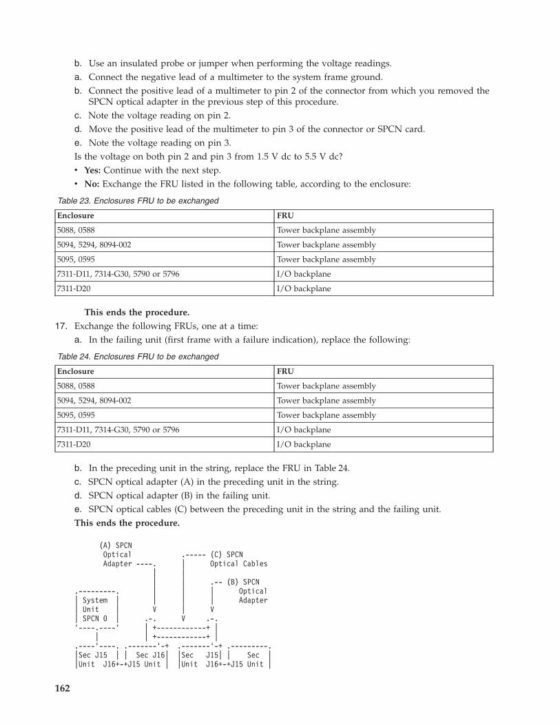
b. Use an insulated probe or jumper when performing the voltage readings.a. Connect the negative lead of a multimeter to the system frame ground.b. Connect the positive lead of a multimeter to pin 2 of the connector from which you removed the
SPCN optical adapter in the previous step of this procedure.c. Note the voltage reading on pin 2.d. Move the positive lead of the multimeter to pin 3 of the connector or SPCN card.e. Note the voltage reading on pin 3.Is the voltage on both pin 2 and pin 3 from 1.5 V dc to 5.5 V dc?v Yes: Continue with the next step.v No: Exchange the FRU listed in the following table, according to the enclosure:
Table 23. Enclosures FRU to be exchanged
Enclosure FRU
5088, 0588 Tower backplane assembly
5094, 5294, 8094-002 Tower backplane assembly
5095, 0595 Tower backplane assembly
7311-D11, 7314-G30, 5790 or 5796 I/O backplane
7311-D20 I/O backplane
This ends the procedure.
17. Exchange the following FRUs, one at a time:a. In the failing unit (first frame with a failure indication), replace the following:
Table 24. Enclosures FRU to be exchanged
Enclosure FRU
5088, 0588 Tower backplane assembly
5094, 5294, 8094-002 Tower backplane assembly
5095, 0595 Tower backplane assembly
7311-D11, 7314-G30, 5790 or 5796 I/O backplane
7311-D20 I/O backplane
b. In the preceding unit in the string, replace the FRU in Table 24.c. SPCN optical adapter (A) in the preceding unit in the string.d. SPCN optical adapter (B) in the failing unit.e. SPCN optical cables (C) between the preceding unit in the string and the failing unit.This ends the procedure.
(A) SPCNOptical .----- (C) SPCNAdapter ----. | Optical Cables
| || | .-- (B) SPCN
.---------. | | | Optical| System | | | | Adapter| Unit | V | V| SPCN 0 | .-. V .-.'----.----' | +------------+ |
| | +------------+ |.----'----. .-------'-+ .-------'-+ .---------.|Sec J15 | | Sec J16| |Sec J15| | Sec ||Unit J16+-+J15 Unit | |Unit J16+-+J15 Unit |
162

| 1 | | 2 | | 3 | | 4 |'---------' '---------' '---------' '---------'
^||'--- Failing Unit
18. Perform the following:a. Power off the system.b. Disconnect the SPCN frame-to-frame cable from the connector of the first unit that cannot be
powered on.c. Connect the negative lead of a multimeter to the system frame ground.d. Connect the positive lead of the multimeter to pin 2 of the SPCN cable.
Note: Use an insulated probe or jumper when performing the voltage readings.e. Note the voltage reading on pin 2.f. Move the positive lead of the multimeter to pin 3 of the SPCN cable.g. Note the voltage reading on pin 3.Is the voltage on both pin 2 and pin 3 from 1.5 V dc to 5.5 V dc?v No: Continue with the next step.v Yes: Exchange the following FRUs one at a time:
a. In the failing unit, replace the FRU listed in the following table:
Table 25. Enclosures FRU to be exchanged
Enclosure FRU
5088, 0588 Tower backplane assembly
5094, 5294, 8094-002 Tower backplane assembly
5095, 0595 Tower backplane assembly
7311-D11, 7314-G30, 5790 or 5796 I/O backplane
7311-D20 I/O backplane
b. In the preceding unit in the string, replace the FRU in Table 25.c. SPCN frame-to-frame cable.This ends the procedure.
19. Perform the following:a. Follow the SPCN frame-to-frame cable back to the preceding unit in the string.b. Disconnect the SPCN cable from the connector.c. Connect the negative lead of a multimeter to the system frame ground.d. Connect the positive lead of a multimeter to pin 2 of the connector.
Note: Use an insulated probe or jumper when performing the voltage readings.e. Note the voltage reading on pin 2.f. Move the positive lead of the multimeter to pin 3 of the connector.g. Note the voltage reading on pin 3.Is the voltage on both pin 2 and pin 3 from 1.5 V dc to 5.5 V dc?v Yes: Exchange the following FRUs one at a time:
a. SPCN frame-to-frame cable.
Beginning troubleshooting and problem analysis 163

b. In the failing unit, replace the following:
Table 26. Enclosures FRU to be exchanged
Enclosure FRU
5088, 0588 Tower backplane assembly
5094, 5294, 8094-002 Tower backplane assembly
5095, 0595 Tower backplane assembly
7311-D11, 7314-G30, 5790 or 5796 I/O backplane
7311-D20 I/O backplane
c. In the preceding unit in the string, replace the FRU in Table 26.This ends the procedure.
v No: Exchange the FRU in Table 26 from the unit from which you disconnected the SPCN cable inthe previous step of this procedure.This ends the procedure.
Cannot power off system or SPCN-controlled I/O expansion unit:
Use this procedure to analyze a failure of the normal command and control panel procedures to poweroff the system unit or an SPCN-controlled I/O expansion unit.
Attention: To prevent loss of data, ask the customer to verify that no interactive jobs are running beforeyou perform this procedure.
For important safety information before continuing with this procedure, see “Power isolation procedures”on page 157.1. Is the power off problem on the system unit?
No: Continue with the next step.Yes: Go to step 3.
2. Ensure that the SPCN cables that connect the units are connected and seated correctly at both ends.Does the I/O unit power off, and is the power indicator light blinking slowly?
Yes: This ends the procedure.
No: Go to step 7 on page 165.3. Attempt to power off the system. Does the system unit power off, and is the power indicator light
blinking slowly?No: Continue with the next step.Yes: The system is not responding to normal power off procedures which could indicate aLicensed Internal Code problem. Contact your next level of support. This ends the procedure.
4. Attempt to power off the system using ASMI. Does the system power off?Yes: The system is not responding to normal power off procedures which could indicate aLicensed Internal Code problem. Contact your next level of support. This ends the procedure.
No: Continue with the next step.5. Attempt to power off the system using the control panel power button. Does the system power off?
Yes: Continue with the next step.No: Go to step 10 on page 165.
6. Is there a reference code logged in either ASMI, the control panel, or the HMC that indicates apower problem?
Yes: Perform problem analysis for the reference code in the log. This ends the procedure.
No: Contact your next level of support. This ends the procedure.
164

7. Is the I/O expansion unit that will not power off part of a shared I/O tower loop?Yes: Go to step 9.No: Continue with the next step.
8. Attempt to power off the I/O expansion unit. Were you able to power off the expansion unit?Yes: This ends the procedure.
No: Go to step 10.9. The unit will only power off under certain conditions:
v If the unit is in private mode, it should power off with the system unit that is connected by theSPCN frame-to-frame cable.
v If the unit is in switchable mode, it should power off if the ″owning″ system is powered off or ispowering off, and the system unit that is connected by the SPCN frame-to-frame cable is poweredoff or is powering off.
Does the I/O expansion unit power off?No: Continue with the next step.Yes: This ends the procedure.
10. Ensure there are no jobs running on the system or partition, and verify that an uninterruptiblepower supply (UPS) is not powering the system or I/O expansion unit. Then continue with the nextstep.
11. Perform the following:a. Remove the system or I/O expansion unit ac power cord from the external UPS or, if an external
UPS is not installed, from the customer’s ac power outlet. If the system or I/O expansion unithas more than one ac line cord, disconnect all the ac line cords.
b. Exchange the following FRUs one at a time. See System FRU locations and System parts forinformation on FRU locations and parts for the system that you are servicing.If the system unit is failing:1) Power supply (Un-E1 or Un-E2). Go to step 122) For 8203-E4A, 9407-M15, 9408-M25, (8204-E8A, 8233-E8B, and 9409-M5,0 exchange the system
backplane (Un-P1). For 8234-EMA, 8234-EMA, 9117-MMA, and 9406-MMA exchange theservice processor (Un-P1-C10). If that does not resolve the problem, exchange the I/Obackplane (Un-P1).
3) System control panel (Un-D1)If an I/O expansion unit is failing:1) Each power supply. Go to step 122) I/O backplane3) I/O backplane in the unit preceding the unit that will not power off4) SPCN frame-to-frame cableThis ends the procedure.
12. A power supply might be the failing item.Attention: When replacing a redundant power supply, a 1xxx 1504, 1514, 1524, or 1534 referencecode may be logged in the error log. If you just removed and replaced the power supply in thelocation associated with this reference code, and the power supply came ready after the install,disregard this reference code. If you had not previously removed and replaced a power supply, thepower supply did not come ready after installation, or there are repeated fan fault errors after thepower supply replacement, continue to follow these steps.Is the reference code 1xxx-15xx?
No: Continue with the next step.Yes: Perform the following:
a. Find the unit reference code in one of the following tables to determine the failing power supply.
Beginning troubleshooting and problem analysis 165

b. Ensure that the power cables are properly connected and seated.c. Is the reference code 1xxx-1500, 1510, 1520, or 1530 and is the failing unit configured with a
redundant power supply option (or dual line cord feature)?v Yes: Perform “PWR1911” on page 168 before replacing parts.v No: Continue with step 12d
d. Refer to System FRU locations for information on FRU locations for the system that you areservicing.
e. Replace the failing power supply (see the following tables to determine which power supply toreplace).
f. If the new power supply does not fix the problem, perform the following :1) Reinstall the original power supply.2) Try the new power supply in each of the other positions listed in the table.3) If the problem still is not fixed, reinstall the original power supply and go to the next FRU in
the list.4) For reference codes 1xxx-1500, 1510, 1520, and 1530, exchange the power distribution
backplane if a problem persists after replacing the power supply.
Table 27. System Unit
Unit Reference Code Power Supply
1510, 1511, 1512, 1513, 1514, 7110 E1
1520, 1521, 1522, 1523, 1524, 7120 E2
Attention: For reference codes 1500, 1510, 1520, and 1530, perform “PWR1911” on page 168 beforereplacing parts.
Table 28. 5088, 0588 expansion units
Unit Reference Code Power Supply
1510, 1511, 1512, 1513, 1514, 1516 P02
1520, 1521, 1522, 1523, 1524, 1526 P01
Attention: On a dual line cord system, for reference codes 1500, 1510, 1520, and 1530, perform“PWR1911” on page 168 before replacing parts. On a single line cord system, check the ac jumper tothe power supply before replacing parts.
Table 29. 5094, 5294 I/O expansion units (single line cord)
Unit Reference Code Power Supply
1510, 1511, 1512, 1513, 1514, 1516 P01
1520, 1521, 1522, 1523, 1524, 1526 P02
1530, 1531, 1532, 1533, 1534, 1536 P03
Attention: On a dual line cord system, for reference codes 1500, 1510, 1520, and 1530, perform“PWR1911” on page 168 before replacing parts. On a single line cord system, check the ac jumper tothe power supply before replacing parts.
Attention: For 5094, 5294 expansion units, do not install power supplies P00 and P01 ac jumpercables on the same ac input module.
166

Table 30. 5094, 5294 I/O expansion units (dual line cord)
Unit Reference Code Power Supply
1500, 1501, 1502, 1503 P00
1510, 1511, 1512, 1513, 1514, 1516 P01
1520, 1521, 1522, 1523, 1524, 1526 P02
1530, 1531, 1532, 1533 P03
Table 31. 5095, 0595, 5790, 7311-D11, 7311-D20, 7314-G30 expansion units
Unit Reference Code Power Supply
1510, 1511, 1512, 1513, 1514, 1516, 1517 P01/E1
1520, 1521, 1522, 1523, 1524, 1526, 1527 P02/E2
This ends the procedure.13. Is the reference code 1xxx-2600, 2603, 2605, or 2606?
v No: Continue with the next step.v Yes: Perform the following:a. Refer to System FRU locations for information on FRU locations for the system you are servicing.b. Replace the failing power supply.c. Perform the following if the new power supply does not fix the problem:
1) Reinstall the original power supply.2) Try the new power supply in each of the other positions listed in the table.3) If the problem still is not fixed, reinstall the original power supply and go to the next FRU in
the list.
Attention: Do not install power supplies P00 and P01 ac jumper cables on the same ac inputmodule.
Table 32. Failing power supplies
System or Feature Code Failing Power Supply
System unit Un-E1, Un-E2
5094, 5294 (single line cord) P01, P02, P03
5094, 5294 (dual line cord) P00, P01, P02, P03
5088, 0588 P02, P01
5095, 0595 P01, P02
5790, 7311-D11, 7311-D20, 7314-G30 E1, E2
This ends the procedure.14. Is the reference code 1xxx 8455 or 8456?
v No: Return to Start of Call. This ends the procedure.
v Yes: One of the power supplies is missing, and must be installed. Use the following table todetermine which power supply is missing, and install the power supply. See System FRU locationsfor information on FRU location for the system you are servicing.
Table 33. Missing power supplies
Reference Code Missing Power Supply
1xxx 8455 Un-E1
1xxx 8456 Un-E2
Beginning troubleshooting and problem analysis 167

This ends the procedure.
PWR1911:
You are here because of a power problem on a dual line cord system. If the failing unit does not have adual line cord, return to the procedure that sent you here or go to the next item in the FRU list.
The following steps are for the system unit, unless other instructions are given. For important safetyinformation before servicing the system, refer to “Power isolation procedures” on page 157.1. If an uninterruptible power supply is installed, verify that it is powered on before proceeding.2. Are all the units powered on?
v Yes: Go to step 7 on page 170.v No: On the unit that does not power on, perform the following:
a. Disconnect the ac line cords from the unit that does not power on.b. Use a multimeter to measure the ac voltage at the system end of both ac line cords.
Table 34. Correct ac voltage
Model or expansion unit Correct ac voltage
Models 8203-E4A, 5095, 0595, and 7311-D20 expansionunits
100 V to 127 V or 200 V to 240 V
Models 8234-EMA, 9117-MMA, 9406-MMA, 5796 and7314-G30 expansion units
200 V to 240 V
5088, 0588, 5094, 5294, 5790, and 7311-D11 expansionunits
200 V to 240 V ac or dc
5095, 0595, and 7311-D20 expansion units 100 V to 127 V or 200 V to 240 V
5802 expansion unit 90 V to 259 V
c. Is the voltage correct (refer to Table 34)?Yes: Continue with the next step.No: Go to step 6 on page 169.
3. Are you working on a system 8203-E4A, 8204-E8A, 8233-E8B, 8234-EMA, 9117-MMA, and9406-MMA, 9407-M15, 9408-M25, 9409-M50, or a 5095, 0595, 5790, 5796, 7314-G30, 7311-D11,7311-D20 expansion unit?v No: Continue with the next step.v Yes: Perform the following:
a. Reconnect the ac line cords.b. Verify that the failing unit fails to power on.c. Replace the failing power supply. Use the table below to determine which power supply needs
replacing, and then see System FRU locations for its location, part number, and exchangeprocedure.
Table 35. Failing power supply for models 8203-E4A, 8204-E8A, 8233-E8B, 8234-EMA, 9117-MMA, and 9406-MMA,9407-M15, 9408-M25, and 9409-M50, or a 5095, 0595, 5790, 5796, 5802 and 5877, 7314-G30, 7311-D11, 7311-D20,8261-E4S expansion units
Reference code Models or expansion units Failing item name
1510 8203-E4A, 8204-E8A, 8233-E8B, 8234-EMA,9117-MMA, and 9406-MMA, 9407-M15,9408-M25, 9409-M50, 8261-E4S
Power supply 1
5095, 0595, 5790, 5796, 7314-G30, 7311-D11,7311-D20, 5802, 5877
Power supply 1
168

Table 35. Failing power supply for models 8203-E4A, 8204-E8A, 8233-E8B, 8234-EMA, 9117-MMA, and 9406-MMA,9407-M15, 9408-M25, and 9409-M50, or a 5095, 0595, 5790, 5796, 5802 and 5877, 7314-G30, 7311-D11, 7311-D20,8261-E4S expansion units (continued)
Reference code Models or expansion units Failing item name
1520 8203-E4A, 8204-E8A, 8233-E8B, 8234-EMA,9117-MMA, and 9406-MMA, 9407-M15,9408-M25, 9409-M50, 8261-E4S
Power supply 2
5095, 0595, 5790, 5796, 7314-G30, 7311-D11,7311-D20, 5802, 5877
Power supply 2
This ends the procedure.
4. Perform the following:a. Reconnect the ac line cord to the ac modules.b. Remove the ac jumper cables at the power supplies.c. Use a multimeter to measure the ac voltage at the power-supply end of the jumper cable.Is the ac voltage from 200 V to 240 V?v No: Continue with the next step.v Yes: Replace the failing power supply. Use the following table to determine which power supply
must be replaced, and then see System FRU locations for its location, part number, and exchangeprocedure.Attention: Do not install power supplies P00 and P01 ac jumper cables on the same ac module.
Table 36. Failing power supply for 5094, 5294, 5088 or 0588 expansion units
Reference code Failing item name
1500 Power supply 0
1510 Power supply 1 for 5094 or 5294
Power supply 2 for 5088 or 0588
1520 Power supply 2 for 5094 or 5294
Power supply 1 for 5088 or 0588
1530 Power supply 3
This ends the procedure.
5. Perform the following:a. Disconnect the ac jumper cable at the ac module output.b. Use a multimeter to measure the ac voltage at the ac module output.Is the ac voltage from 200 V to 240 V?v Yes: Exchange the ac jumper cable.
This ends the procedure.
v No: Exchange the ac module. See System FRU locations for FRU location information for thesystem that you are servicing.This ends the procedure.
6. Perform the following:a. Disconnect the ac line cords from the customer’s ac power outlet.b. Use a multimeter to measure the ac voltage at the customer’s ac power outlet.Is the ac voltage correct (refer to Table 34 on page 168)?v Yes: Exchange the failing ac line cord.
This ends the procedure.
Beginning troubleshooting and problem analysis 169

v No: Perform the following:a. Inform the customer that the ac voltage at the power outlet is not correct.b. Reconnect the ac line cords to the power outlet after the ac voltage at the power outlet is
correct.This ends the procedure.
7. Is the reference code 1xxx00AC?v No: Continue with the next step.v Yes: This reference code may have been caused by an ac outage. If the system will power on
without an error, no parts need to be replaced.This ends the procedure.
8. Is the reference code 1xxx1510 or 1520?v No: Continue with the next step.v Yes: Perform the following:
a. Use the following table, figures and location codes to locate the failing parts. See System FRUlocations for information on FRU location for the system that you are servicing..
Table 37. Power Reference Code Table
Model or expansion unit Reference code Locate these parts
8203-E4A, 8204-E8A,8233-E8B, 8234-EMA,9117-MMA, and 9406-MMA,9407-M15, 9408-M25,9409-M50, 8261-E4S
1xxx 1510 Power supply E1 and ac line cord 1
1xxx 1520 Power supply E2 and ac line cord 2
5088 and 0588 (see Figure 7on page 172)
1xxx 1510 ac jumper cable connected to powersupply 2 and the ac module
1xxx 1520 ac jumper cable connected to powersupply 1 and the ac module
5294 and 5094 (see Figure 6on page 171)
1xxx 1500 ac jumper cable connected to powersupply 0 and the ac module
1xxx 1510 ac jumper cable connected to powersupply 1 and the ac module
1xxx 1520 ac jumper cable connected to powersupply 2 and the ac module
1xxx 1530 ac jumper cable connected to powersupply 3 and the ac module
5095 and 0595 1xxx 1510 Power supply 1 and ac line cord 1
1xxx 1520 Power supply 2 and ac line cord 2
5790, 5796, 7314-G30,7311-D11, 7311-D20, 5802,5877
1xxx 1510 Power supply 1 and ac line cord 1
1xxx 1520 Power supply 2 and ac line cord 2
170

Figure 6. Dual line cord drawing for 5094
Beginning troubleshooting and problem analysis 171

b. Locate the ac line cord or the ac jumper cable for the reference code you are working on.c. Go to step 10.
9. Is the reference code 1xxx 1500 or 1xxx 1530?v No: Perform Problem Analysis using the reference code.
This ends the procedure.
v Yes: Locate the ac jumper cables for the reference code you are working on (see Table 37 on page170), and then continue with the next step:– If the reference code is 1xxx 1500, determine the locations of ac jumper cables that connect to
power supply P00 (see the preceding figures).– If the reference code is 1xxx 1530, determine the locations of ac jumper cables that connect to
power supply P03 (see the preceding figures).10. Perform the following:
Attention: Do not disconnect the other system line cord when powered on.Attention: Do not disconnect the other ac jumper cable when powered on.a. For the reference code you are working on, disconnect either the ac jumper cable or the ac line
cord from the power supply.b. Use a multimeter to measure the ac voltage at the power supply end of the ac jumper cable or
the ac line cord.
Figure 7. Dual line cord drawing for 5088, or 0588 installed on 5094
172

Is the ac voltage correct (see Table 34 on page 168)?No: Continue with the next step.Yes: Exchange the failing power supply. Refer to Table 35 on page 168 and Table 36 on page 169for its position, and then see System FRU locations for part numbers and directions to the correctexchange procedures. This ends the procedure.
11. Perform the following:a. Disconnect the ac line cords from the power outlet.b. Use a multimeter to measure the ac voltage at the customer’s ac power outlet.Is the ac voltage correct (see Table 34 on page 168)?v Yes: Exchange the following, one at a time:
– Failing ac line cord– Failing ac jumper cable (if installed)– Failing ac module (if installed) (see System FRU locations for part numbers and directions to
the correct exchange procedures)This ends the procedure.
v No: Perform the following:a. Inform the customer that the ac voltage at the power outlet is not correct.b. Reconnect the ac line cords to the power outlet after the ac voltage at the power outlet is
correct.This ends the procedure.
Beginning troubleshooting and problem analysis 173

174

Appendix. Notices
This information was developed for products and services offered in the U.S.A.
The manufacturer may not offer the products, services, or features discussed in this document in othercountries. Consult the manufacturer’s representative for information on the products and servicescurrently available in your area. Any reference to the manufacturer’s product, program, or service is notintended to state or imply that only that product, program, or service may be used. Any functionallyequivalent product, program, or service that does not infringe any intellectual property right of themanufacturer may be used instead. However, it is the user’s responsibility to evaluate and verify theoperation of any product, program, or service.
The manufacturer may have patents or pending patent applications covering subject matter described inthis document. The furnishing of this document does not grant you any license to these patents. You cansend license inquiries, in writing, to the manufacturer.
The following paragraph does not apply to the United Kingdom or any other country where suchprovisions are inconsistent with local law: THIS INFORMATION IS PROVIDED “AS IS” WITHOUTWARRANTY OF ANY KIND, EITHER EXPRESS OR IMPLIED, INCLUDING, BUT NOT LIMITED TO,THE IMPLIED WARRANTIES OF NON-INFRINGEMENT, MERCHANTABILITY OR FITNESS FOR APARTICULAR PURPOSE. Some states do not allow disclaimer of express or implied warranties in certaintransactions, therefore, this statement may not apply to you.
This information could include technical inaccuracies or typographical errors. Changes are periodicallymade to the information herein; these changes will be incorporated in new editions of the publication.The manufacturer may make improvements and/or changes in the product(s) and/or the program(s)described in this publication at any time without notice.
Any references in this information to Web sites not owned by the manufacturer are provided forconvenience only and do not in any manner serve as an endorsement of those Web sites. The materials atthose Web sites are not part of the materials for this product and use of those Web sites is at your ownrisk.
The manufacturer may use or distribute any of the information you supply in any way it believesappropriate without incurring any obligation to you.
Any performance data contained herein was determined in a controlled environment. Therefore, theresults obtained in other operating environments may vary significantly. Some measurements may havebeen made on development-level systems and there is no guarantee that these measurements will be thesame on generally available systems. Furthermore, some measurements may have been estimated throughextrapolation. Actual results may vary. Users of this document should verify the applicable data for theirspecific environment.
Information concerning products not produced by this manufacturer was obtained from the suppliers ofthose products, their published announcements or other publicly available sources. This manufacturer hasnot tested those products and cannot confirm the accuracy of performance, compatibility or any otherclaims related to products not produced by this manufacturer. Questions on the capabilities of productsnot produced by this manufacturer should be addressed to the suppliers of those products.
All statements regarding the manufacturer’s future direction or intent are subject to change or withdrawalwithout notice, and represent goals and objectives only.
© Copyright IBM Corp. 2007, 2009 175

The manufacturer’s prices shown are the manufacturer’s suggested retail prices, are current and aresubject to change without notice. Dealer prices may vary.
This information is for planning purposes only. The information herein is subject to change before theproducts described become available.
This information contains examples of data and reports used in daily business operations. To illustratethem as completely as possible, the examples include the names of individuals, companies, brands, andproducts. All of these names are fictitious and any similarity to the names and addresses used by anactual business enterprise is entirely coincidental.
If you are viewing this information in softcopy, the photographs and color illustrations may not appear.
The drawings and specifications contained herein shall not be reproduced in whole or in part without thewritten permission of the manufacturer.
The manufacturer has prepared this information for use with the specific machines indicated. Themanufacturer makes no representations that it is suitable for any other purpose.
The manufacturer’s computer systems contain mechanisms designed to reduce the possibility ofundetected data corruption or loss. This risk, however, cannot be eliminated. Users who experienceunplanned outages, system failures, power fluctuations or outages, or component failures must verify theaccuracy of operations performed and data saved or transmitted by the system at or near the time of theoutage or failure. In addition, users must establish procedures to ensure that there is independent dataverification before relying on such data in sensitive or critical operations. Users should periodically checkthe manufacturer’s support websites for updated information and fixes applicable to the system andrelated software.
TrademarksIBM, the IBM logo, and ibm.com are trademarks or registered trademarks of International BusinessMachines Corp., registered in many jurisdictions worldwide. Other product and service names might betrademarks of IBM or other companies. A current list of IBM trademarks is available on the Web atCopyright and trademark information at www.ibm.com/legal/copytrade.shtml.
INFINIBAND, InfiniBand Trade Association, and the INFINIBAND design marks are trademarks and/orservice marks of the INFINIBAND Trade Association.
Linux is a registered trademark of Linus Torvalds in the United States, other countries, or both.
Other company, product, or service names may be trademarks or service marks of others.
Electronic emission notices
Class A NoticesThe following Class A statements apply to the IBM servers that contain the POWER6 processor.
Federal Communications Commission (FCC) statement
Note: This equipment has been tested and found to comply with the limits for a Class A digital device,pursuant to Part 15 of the FCC Rules. These limits are designed to provide reasonable protection againstharmful interference when the equipment is operated in a commercial environment. This equipmentgenerates, uses, and can radiate radio frequency energy and, if not installed and used in accordance withthe instruction manual, may cause harmful interference to radio communications. Operation of this
176

equipment in a residential area is likely to cause harmful interference, in which case the user will berequired to correct the interference at his own expense.
Properly shielded and grounded cables and connectors must be used in order to meet FCC emissionlimits. IBM is not responsible for any radio or television interference caused by using other thanrecommended cables and connectors or by unauthorized changes or modifications to this equipment.Unauthorized changes or modifications could void the user’s authority to operate the equipment.
This device complies with Part 15 of the FCC rules. Operation is subject to the following two conditions:(1) this device may not cause harmful interference, and (2) this device must accept any interferencereceived, including interference that may cause undesired operation.
Industry Canada Compliance Statement
This Class A digital apparatus complies with Canadian ICES-003.
Avis de conformité à la réglementation d’Industrie Canada
Cet appareil numérique de la classe A respecte est conforme à la norme NMB-003 du Canada.
European Community Compliance Statement
This product is in conformity with the protection requirements of EU Council Directive 2004/108/EC onthe approximation of the laws of the Member States relating to electromagnetic compatibility. IBM cannotaccept responsibility for any failure to satisfy the protection requirements resulting from anon-recommended modification of the product, including the fitting of non-IBM option cards.
This product has been tested and found to comply with the limits for Class A Information TechnologyEquipment according to European Standard EN 55022. The limits for Class A equipment were derived forcommercial and industrial environments to provide reasonable protection against interference withlicensed communication equipment.
European Community contact:IBM Technical RegulationsPascalstr. 100, Stuttgart, Germany 70569Tele: 0049 (0)711 785 1176Fax: 0049 (0)711 785 1283E-mail: [email protected]
Warning: This is a Class A product. In a domestic environment, this product may cause radiointerference, in which case the user may be required to take adequate measures.
VCCI Statement - Japan
The following is a summary of the VCCI Japanese statement in the box above:
This is a Class A product based on the standard of the VCCI Council. If this equipment is used in adomestic environment, radio interference may occur, in which case, the user may be required to takecorrective actions.
Appendix. Notices 177

Japanese Electronics and Information Technology Industries Association (JEITA)Confirmed Harmonics Guideline (products less than or equal to 20 A per phase)
Japanese Electronics and Information Technology Industries Association (JEITA)Confirmed Harmonics Guideline with Modifications (products greater than 20 A perphase)
Electromagnetic Interference (EMI) Statement - People’s Republic of China
Declaration: This is a Class A product. In a domestic environment this product may cause radiointerference in which case the user may need to perform practical action.
Electromagnetic Interference (EMI) Statement - Taiwan
The following is a summary of the EMI Taiwan statement above.
Warning: This is a Class A product. In a domestic environment this product may cause radio interferencein which case the user will be required to take adequate measures.
IBM Taiwan Contact Information:
178

Electromagnetic Interference (EMI) Statement - Korea
Please note that this equipment has obtained EMC registration for commercial use. In the event that ithas been mistakenly sold or purchased, please exchange it for equipment certified for home use.
Germany Compliance Statement
Deutschsprachiger EU Hinweis: Hinweis für Geräte der Klasse A EU-Richtlinie zurElektromagnetischen Verträglichkeit
Dieses Produkt entspricht den Schutzanforderungen der EU-Richtlinie 2004/108/EG zur Angleichung derRechtsvorschriften über die elektromagnetische Verträglichkeit in den EU-Mitgliedsstaaten und hält dieGrenzwerte der EN 55022 Klasse A ein.
Um dieses sicherzustellen, sind die Geräte wie in den Handbüchern beschrieben zu installieren und zubetreiben. Des Weiteren dürfen auch nur von der IBM empfohlene Kabel angeschlossen werden. IBMübernimmt keine Verantwortung für die Einhaltung der Schutzanforderungen, wenn das Produkt ohneZustimmung der IBM verändert bzw. wenn Erweiterungskomponenten von Fremdherstellern ohneEmpfehlung der IBM gesteckt/eingebaut werden.
EN 55022 Klasse A Geräte müssen mit folgendem Warnhinweis versehen werden:″Warnung: Dieses ist eine Einrichtung der Klasse A. Diese Einrichtung kann im WohnbereichFunk-Störungen verursachen; in diesem Fall kann vom Betreiber verlangt werden, angemesseneMaßnahmen zu ergreifen und dafür aufzukommen.″
Deutschland: Einhaltung des Gesetzes über die elektromagnetische Verträglichkeit von Geräten
Dieses Produkt entspricht dem “Gesetz über die elektromagnetische Verträglichkeit von Geräten(EMVG)“. Dies ist die Umsetzung der EU-Richtlinie 2004/108/EG in der Bundesrepublik Deutschland.
Zulassungsbescheinigung laut dem Deutschen Gesetz über die elektromagnetische Verträglichkeit vonGeräten (EMVG) (bzw. der EMC EG Richtlinie 2004/108/EG) für Geräte der Klasse A.
Dieses Gerät ist berechtigt, in Übereinstimmung mit dem Deutschen EMVG das EG-Konformitätszeichen- CE - zu führen.
Verantwortlich für die Konformitätserklärung nach des EMVG ist die IBM Deutschland GmbH, 70548Stuttgart.
Appendix. Notices 179

Generelle Informationen:
Das Gerät erfüllt die Schutzanforderungen nach EN 55024 und EN 55022 Klasse A.
Electromagnetic Interference (EMI) Statement - Russia
Terms and conditionsPermissions for the use of these publications is granted subject to the following terms and conditions.
Personal Use: You may reproduce these publications for your personal, noncommercial use provided thatall proprietary notices are preserved. You may not distribute, display or make derivative works of thesepublications, or any portion thereof, without the express consent of the manufacturer.
Commercial Use: You may reproduce, distribute and display these publications solely within yourenterprise provided that all proprietary notices are preserved. You may not make derivative works ofthese publications, or reproduce, distribute or display these publications or any portion thereof outsideyour enterprise, without the express consent of the manufacturer.
Except as expressly granted in this permission, no other permissions, licenses or rights are granted, eitherexpress or implied, to the publications or any data, software or other intellectual property containedtherein.
The manufacturer reserves the right to withdraw the permissions granted herein whenever, in itsdiscretion, the use of the publications is detrimental to its interest or, as determined by the manufacturer,the above instructions are not being properly followed.
You may not download, export or re-export this information except in full compliance with all applicablelaws and regulations, including all United States export laws and regulations.
THE MANUFACTURER MAKES NO GUARANTEE ABOUT THE CONTENT OF THESEPUBLICATIONS. THESE PUBLICATIONS ARE PROVIDED ″AS-IS″ AND WITHOUT WARRANTY OFANY KIND, EITHER EXPRESSED OR IMPLIED, INCLUDING BUT NOT LIMITED TO IMPLIEDWARRANTIES OF MERCHANTABILITY, NON-INFRINGEMENT, AND FITNESS FOR A PARTICULARPURPOSE.
180


����
Printed in USA