Embed Size (px)
Citation preview

Power Systems
Managing system managementservices
���


Power Systems
Managing system managementservices
���

NoteBefore using this information and the product it supports, read the information in “Safety notices” on page v, “Notices” onpage 19, the IBM Systems Safety Notices manual, G229-9054, and the IBM Environmental Notices and User Guide, Z125–5823.
This edition applies to IBM Power Systems servers that contain the POWER7 processor and to all associatedmodels.
© Copyright IBM Corporation 2010, 2012.US Government Users Restricted Rights – Use, duplication or disclosure restricted by GSA ADP Schedule Contractwith IBM Corp.

Contents
Safety notices . . . . . . . . . . . . . . . . . . . . . . . . . . . . . . . . . v
Managing system management services. . . . . . . . . . . . . . . . . . . . . . 1What's new in Managing system management services . . . . . . . . . . . . . . . . . . . . . 1Starting system management services . . . . . . . . . . . . . . . . . . . . . . . . . . . 1
Starting system management services from a logically partitioned server . . . . . . . . . . . . . . 1Starting system management services from a nonpartitioned server . . . . . . . . . . . . . . . . 2
Starting the SMS menus from the ASMI . . . . . . . . . . . . . . . . . . . . . . . . 2Starting the SMS menus when the ASMI is not available and the system is in standby. . . . . . . . . 2
Using system management services. . . . . . . . . . . . . . . . . . . . . . . . . . . . 3Menus and descriptions . . . . . . . . . . . . . . . . . . . . . . . . . . . . . . 3Main menu and navigation . . . . . . . . . . . . . . . . . . . . . . . . . . . . . 4Selecting the language in system management services . . . . . . . . . . . . . . . . . . . . 4Setting up a remote IPL . . . . . . . . . . . . . . . . . . . . . . . . . . . . . . 5
Selecting the BOOTP or TFTP option . . . . . . . . . . . . . . . . . . . . . . . . . 6Selecting the ISCSI option . . . . . . . . . . . . . . . . . . . . . . . . . . . . . 8
Configuring adapters . . . . . . . . . . . . . . . . . . . . . . . . . . . . . . . 10Selecting the speed, duplex option. . . . . . . . . . . . . . . . . . . . . . . . . . 10Selecting the protocol option . . . . . . . . . . . . . . . . . . . . . . . . . . . 10
Changing SCSI settings . . . . . . . . . . . . . . . . . . . . . . . . . . . . . . 10Selecting the console . . . . . . . . . . . . . . . . . . . . . . . . . . . . . . . 11Selecting boot options . . . . . . . . . . . . . . . . . . . . . . . . . . . . . . . 11
Selecting to install or boot a device . . . . . . . . . . . . . . . . . . . . . . . . . 11Configuring boot device order . . . . . . . . . . . . . . . . . . . . . . . . . . . 13Multiboot startup . . . . . . . . . . . . . . . . . . . . . . . . . . . . . . . 17SAN zoning support . . . . . . . . . . . . . . . . . . . . . . . . . . . . . . 17
Power-on self-test keys . . . . . . . . . . . . . . . . . . . . . . . . . . . . . . . 17Exiting system management services . . . . . . . . . . . . . . . . . . . . . . . . . . . 18
Notices . . . . . . . . . . . . . . . . . . . . . . . . . . . . . . . . . . . 19Trademarks . . . . . . . . . . . . . . . . . . . . . . . . . . . . . . . . . . . 20Electronic emission notices . . . . . . . . . . . . . . . . . . . . . . . . . . . . . . 20
Class A Notices . . . . . . . . . . . . . . . . . . . . . . . . . . . . . . . . . 20Class B Notices . . . . . . . . . . . . . . . . . . . . . . . . . . . . . . . . . 24
Terms and conditions . . . . . . . . . . . . . . . . . . . . . . . . . . . . . . . . 27
© Copyright IBM Corp. 2010, 2012 iii

iv Power Systems: Managing system management services

Safety notices
Safety notices may be printed throughout this guide:v DANGER notices call attention to a situation that is potentially lethal or extremely hazardous to
people.v CAUTION notices call attention to a situation that is potentially hazardous to people because of some
existing condition.v Attention notices call attention to the possibility of damage to a program, device, system, or data.
World Trade safety information
Several countries require the safety information contained in product publications to be presented in theirnational languages. If this requirement applies to your country, safety information documentation isincluded in the publications package (such as in printed documentation, on DVD, or as part of theproduct) shipped with the product. The documentation contains the safety information in your nationallanguage with references to the U.S. English source. Before using a U.S. English publication to install,operate, or service this product, you must first become familiar with the related safety informationdocumentation. You should also refer to the safety information documentation any time you do notclearly understand any safety information in the U.S. English publications.
Replacement or additional copies of safety information documentation can be obtained by calling the IBMHotline at 1-800-300-8751.
German safety information
Das Produkt ist nicht für den Einsatz an Bildschirmarbeitsplätzen im Sinne § 2 derBildschirmarbeitsverordnung geeignet.
Laser safety information
IBM® servers can use I/O cards or features that are fiber-optic based and that utilize lasers or LEDs.
Laser compliance
IBM servers may be installed inside or outside of an IT equipment rack.
© Copyright IBM Corp. 2010, 2012 v

DANGER
When working on or around the system, observe the following precautions:
Electrical voltage and current from power, telephone, and communication cables are hazardous. Toavoid a shock hazard:v Connect power to this unit only with the IBM provided power cord. Do not use the IBM
provided power cord for any other product.v Do not open or service any power supply assembly.v Do not connect or disconnect any cables or perform installation, maintenance, or reconfiguration
of this product during an electrical storm.v The product might be equipped with multiple power cords. To remove all hazardous voltages,
disconnect all power cords.v Connect all power cords to a properly wired and grounded electrical outlet. Ensure that the outlet
supplies proper voltage and phase rotation according to the system rating plate.v Connect any equipment that will be attached to this product to properly wired outlets.v When possible, use one hand only to connect or disconnect signal cables.v Never turn on any equipment when there is evidence of fire, water, or structural damage.v Disconnect the attached power cords, telecommunications systems, networks, and modems before
you open the device covers, unless instructed otherwise in the installation and configurationprocedures.
v Connect and disconnect cables as described in the following procedures when installing, moving,or opening covers on this product or attached devices.
To Disconnect:1. Turn off everything (unless instructed otherwise).2. Remove the power cords from the outlets.3. Remove the signal cables from the connectors.4. Remove all cables from the devices.
To Connect:1. Turn off everything (unless instructed otherwise).2. Attach all cables to the devices.3. Attach the signal cables to the connectors.4. Attach the power cords to the outlets.5. Turn on the devices.
(D005)
DANGER
vi Power Systems: Managing system management services

Observe the following precautions when working on or around your IT rack system:
v Heavy equipment–personal injury or equipment damage might result if mishandled.
v Always lower the leveling pads on the rack cabinet.
v Always install stabilizer brackets on the rack cabinet.
v To avoid hazardous conditions due to uneven mechanical loading, always install the heaviestdevices in the bottom of the rack cabinet. Always install servers and optional devices startingfrom the bottom of the rack cabinet.
v Rack-mounted devices are not to be used as shelves or work spaces. Do not place objects on topof rack-mounted devices.
v Each rack cabinet might have more than one power cord. Be sure to disconnect all power cords inthe rack cabinet when directed to disconnect power during servicing.
v Connect all devices installed in a rack cabinet to power devices installed in the same rackcabinet. Do not plug a power cord from a device installed in one rack cabinet into a powerdevice installed in a different rack cabinet.
v An electrical outlet that is not correctly wired could place hazardous voltage on the metal parts ofthe system or the devices that attach to the system. It is the responsibility of the customer toensure that the outlet is correctly wired and grounded to prevent an electrical shock.
CAUTION
v Do not install a unit in a rack where the internal rack ambient temperatures will exceed themanufacturer's recommended ambient temperature for all your rack-mounted devices.
v Do not install a unit in a rack where the air flow is compromised. Ensure that air flow is notblocked or reduced on any side, front, or back of a unit used for air flow through the unit.
v Consideration should be given to the connection of the equipment to the supply circuit so thatoverloading of the circuits does not compromise the supply wiring or overcurrent protection. Toprovide the correct power connection to a rack, refer to the rating labels located on theequipment in the rack to determine the total power requirement of the supply circuit.
v (For sliding drawers.) Do not pull out or install any drawer or feature if the rack stabilizer bracketsare not attached to the rack. Do not pull out more than one drawer at a time. The rack mightbecome unstable if you pull out more than one drawer at a time.
v (For fixed drawers.) This drawer is a fixed drawer and must not be moved for servicing unlessspecified by the manufacturer. Attempting to move the drawer partially or completely out of therack might cause the rack to become unstable or cause the drawer to fall out of the rack.
(R001)
Safety notices vii

CAUTION:Removing components from the upper positions in the rack cabinet improves rack stability duringrelocation. Follow these general guidelines whenever you relocate a populated rack cabinet within aroom or building:
v Reduce the weight of the rack cabinet by removing equipment starting at the top of the rackcabinet. When possible, restore the rack cabinet to the configuration of the rack cabinet as youreceived it. If this configuration is not known, you must observe the following precautions:
– Remove all devices in the 32U position and above.
– Ensure that the heaviest devices are installed in the bottom of the rack cabinet.
– Ensure that there are no empty U-levels between devices installed in the rack cabinet below the32U level.
v If the rack cabinet you are relocating is part of a suite of rack cabinets, detach the rack cabinet fromthe suite.
v Inspect the route that you plan to take to eliminate potential hazards.
v Verify that the route that you choose can support the weight of the loaded rack cabinet. Refer to thedocumentation that comes with your rack cabinet for the weight of a loaded rack cabinet.
v Verify that all door openings are at least 760 x 230 mm (30 x 80 in.).
v Ensure that all devices, shelves, drawers, doors, and cables are secure.
v Ensure that the four leveling pads are raised to their highest position.
v Ensure that there is no stabilizer bracket installed on the rack cabinet during movement.
v Do not use a ramp inclined at more than 10 degrees.
v When the rack cabinet is in the new location, complete the following steps:
– Lower the four leveling pads.
– Install stabilizer brackets on the rack cabinet.
– If you removed any devices from the rack cabinet, repopulate the rack cabinet from the lowestposition to the highest position.
v If a long-distance relocation is required, restore the rack cabinet to the configuration of the rackcabinet as you received it. Pack the rack cabinet in the original packaging material, or equivalent.Also lower the leveling pads to raise the casters off of the pallet and bolt the rack cabinet to thepallet.
(R002)
(L001)
(L002)
viii Power Systems: Managing system management services

(L003)
or
All lasers are certified in the U.S. to conform to the requirements of DHHS 21 CFR Subchapter J for class1 laser products. Outside the U.S., they are certified to be in compliance with IEC 60825 as a class 1 laserproduct. Consult the label on each part for laser certification numbers and approval information.
CAUTION:This product might contain one or more of the following devices: CD-ROM drive, DVD-ROM drive,DVD-RAM drive, or laser module, which are Class 1 laser products. Note the following information:
v Do not remove the covers. Removing the covers of the laser product could result in exposure tohazardous laser radiation. There are no serviceable parts inside the device.
v Use of the controls or adjustments or performance of procedures other than those specified hereinmight result in hazardous radiation exposure.
(C026)
Safety notices ix

CAUTION:Data processing environments can contain equipment transmitting on system links with laser modulesthat operate at greater than Class 1 power levels. For this reason, never look into the end of an opticalfiber cable or open receptacle. (C027)
CAUTION:This product contains a Class 1M laser. Do not view directly with optical instruments. (C028)
CAUTION:Some laser products contain an embedded Class 3A or Class 3B laser diode. Note the followinginformation: laser radiation when open. Do not stare into the beam, do not view directly with opticalinstruments, and avoid direct exposure to the beam. (C030)
CAUTION:The battery contains lithium. To avoid possible explosion, do not burn or charge the battery.
Do Not:v ___ Throw or immerse into waterv ___ Heat to more than 100°C (212°F)v ___ Repair or disassemble
Exchange only with the IBM-approved part. Recycle or discard the battery as instructed by localregulations. In the United States, IBM has a process for the collection of this battery. For information,call 1-800-426-4333. Have the IBM part number for the battery unit available when you call. (C003)
Power and cabling information for NEBS (Network Equipment-Building System)GR-1089-CORE
The following comments apply to the IBM servers that have been designated as conforming to NEBS(Network Equipment-Building System) GR-1089-CORE:
The equipment is suitable for installation in the following:v Network telecommunications facilitiesv Locations where the NEC (National Electrical Code) applies
The intrabuilding ports of this equipment are suitable for connection to intrabuilding or unexposedwiring or cabling only. The intrabuilding ports of this equipment must not be metallically connected to theinterfaces that connect to the OSP (outside plant) or its wiring. These interfaces are designed for use asintrabuilding interfaces only (Type 2 or Type 4 ports as described in GR-1089-CORE) and require isolationfrom the exposed OSP cabling. The addition of primary protectors is not sufficient protection to connectthese interfaces metallically to OSP wiring.
Note: All Ethernet cables must be shielded and grounded at both ends.
The ac-powered system does not require the use of an external surge protection device (SPD).
The dc-powered system employs an isolated DC return (DC-I) design. The DC battery return terminalshall not be connected to the chassis or frame ground.
x Power Systems: Managing system management services
Managing system management services
Use the menus within system management services (SMS) to view information about your system orpartition and to perform tasks, such as changing the boot list and setting the network parameters. Thesemenus can be used for AIX® or Linux logical partitions, for the Virtual I/O Server (VIOS), and for theIntegrated Virtualization Manager (IVM).
What's new in Managing system management servicesRead about new or significantly changed information in Managing system management services since theprevious update of this topic collection.
October 2013v Added information about the new option ping test for the ISCSI Discovery Selection. Use this option to
perform the ping test for client IP address, server IP address, gateway IP address or subnet mask.– Selecting the ISCSI option
v Updated a menu item in the Select Device Type in configuring the boot order menu.– Configuring boot device order
October 2012v Added information about the new options for the Advanced Setup option to support multiple VLANs
in a bridged network. Use this option to share the physical network link.– “Selecting the BOOTP or TFTP option” on page 6
May 2012v Added information about the new option on the Boot Options menu that supports storage area
network (SAN) zoning.– Selecting boot options– SAN zoning support
February 2010v Added information for IBM Power Systems™ servers that contain the POWER7® processor.
Starting system management servicesLearn how to start system management services (SMS) from a partitioned or nonpartitioned server.Related concepts:“Power-on self-test keys” on page 17The power-on self-test (POST) keys can start services or initiate service mode boots used for configuringthe system and diagnosing problems.
Starting system management services from a logically partitionedserverLearn how to start system management services (SMS) from a partitioned server using a HardwareManagement Console (HMC).
If you have a logically partitioned system, complete the following tasks:
© Copyright IBM Corp. 2010, 2012 1

Requirement: The logical partition must be shut down, and you must set the partition to start in SMSmode to access SMS.1. In the navigation area, select Systems Management > Servers.2. In the navigation area, select the managed system that you want to work with.3. In the contents area, select the logical partition that you want to work with.4. Select Configuration > Manage Profiles.5. In the Manage Profiles window, select the logical partition that you want to work with.6. Select Actions > Edit.7. Click on the Settings tab.8. In the Boot Modes section, select SMS.9. Click OK.
10. Restart the logical partition by selecting Operations > Restart in the HMC window. The SMS menusare displayed on the console.
11. If you do not already have a console for this session, select Open a terminal window or consolesession, and click OK.
The system starts and the SMS menus are shown on the session's console.
Starting system management services from a nonpartitioned serverLearn how to start system management services (SMS) menus using the Advanced System ManagementInterface (ASMI), the control panel, or from the AIX operating system.
Starting the SMS menus from the ASMIIf the ASMI is available on a network-attached console and the system is in standby, perform thefollowing steps:1. On the ASMI Welcome window, specify your user ID and password, and click Log In.2. In the navigation area, expand Power/Restart Control and select Power On/Off System.3. Click Save settings and continue system server firmware boot.4. Look for the POST indicators memory, keyboard, network, scsi, speaker, which display across the
bottom of the firmware console. For details, see “Power-on self-test keys” on page 17.5. Press the numeric 1 key after the word keyboard is displayed and before the word speaker is
displayed.6. If requested, accept the firmware agreement7. If requested, select a language. For details on the available languages, see Selecting the language in
system management services.8. If requested, enter a password. Enter the admin password that you set during initial system setup.
Starting the SMS menus when the ASMI is not available and the system is instandbyIf the ASMI is not available and the system is in standby, complete the following steps:1. Press the power button on the control panel.2. Look for the POST indicators memory, keyboard, network, scsi, speaker, which display across the
bottom of the firmware console. For details, see “Power-on self-test keys” on page 17.3. Press the numeric 1 key after the word keyboard is displayed and before the word speaker is
displayed.4. If requested, accept the firmware agreement5. If requested, select a language. For details on the available languages, see Selecting the language in
system management services.6. If requested, enter a password. Enter the admin password that you set during initial system setup.
2 Power Systems: Managing system management services

Using system management servicesLearn how the system management services (SMS) menus can help you manage your system.Related tasks:“Starting system management services” on page 1Learn how to start system management services (SMS) from a partitioned or nonpartitioned server.
Menus and descriptionsThere are many tasks that you can access using the system management services (SMS) menus.
If you have not performed the steps to start the system management services, see “Starting systemmanagement services” on page 1.
Notes:
v If the firmware console is a graphics terminal, you might need to enter the password for the serviceprocessor's admin user that was set using the Advanced System Management Interface (ASMI).
v In a partitioned server, SMS menus display only those devices that are assigned to the partition that isbeing booted. In a partition that uses all the resources in a server, SMS menus display all devices in thesystem.
v In some of the following example menus, Un is used in place of Ufeature_code.model.serial number forlegibility.
The following table contains the titles of the menus or tasks that can be accessed using the SMS menus.Use it to access and review the specific task that you want. These titles and menu contents are subject tochange. Do not rely on exact content, such as with scripting.
Table 1. SMS menus and descriptions
Menu or task Description
Main menu Displays the opening menu when first starting SMS.
Select language Changes the language used by the SMS menus.
Setup remote IPL Enables and sets up the remote startup capability of your server.
Adapter configuration Sets both the network speed and the protocol.
Speed, duplex Sets the interface speed at which the adapter runs and you can select half orfull duplex.
Protocol Sets the appropriate protocol for your network.
Ping test Tests an adapter's network connection to a remote system.
Advanced setup: BOOTP Changes the BOOTP values.
Change SCSI settings Changes the addresses of the SCSI controllers attached to your system.
Select console Selects which console to use to display the SMS menus.
Select boot options Sets various options regarding the installation devices and boot devices. TheSelect boot options menu provides the following options: Select Install orBoot Device, Select Boot Devices, Multiboot Startup, and SAN ZoningSupport.
Normal mode boot or service modeboot
Performs a boot in the normal or service mode.
Hard drive Displays a menu that identifies the different types of bootable disk drivesinstalled on your system, for example, SCSI.
Set boot sequence Sets the location of the device in the boot list. The Set boot sequence menuprovides the following options: display current settings, restore defaultsettings, multiboot startup, and exiting system management services.
Managing system management services 3

Main menu and navigationFrom the main menu, you can select a language, set up remote IPLs, change SCSI settings, select aconsole, and select boot options.
After the SMS starts, a menu similar to the following example is displayed.
Main Menu
1. Select Language2. Setup Remote IPL (Initial Program Load)3. Change SCSI Settings4. Select Console5. Select Boot Options6. Firmware Boot Side Options7. Progress Indicator History
--------------------------------------------------------------------------------Navigation keys:
X = eXit System Management Services--------------------------------------------------------------------------------Type the number of the menu item and press Enter or Select a Navigation key: _
On all menus except the main menu, you can use several navigation keys:
M Return to the main menu.
ESC Return to the previous menu.
X Exit the SMS and start the operating system.
If you enter X, you are asked to confirm your choice to exit the SMS menus and start theoperating system.
When more than one page of information can be displayed, two additional navigation keys are available:
N Display the next page of the list.
P Display the previous page of the list.
Note: The lowercase navigation key has the same effect as the uppercase key that is shown on the menu.For example, m or M returns you to the main menu.
On each menu, you can choose a menu item and press Enter (if applicable), or select a navigation key.
Selecting the language in system management servicesYou can choose from among a range of language options in the system management services.
When you select the Select Language option, you can change the language used by the SMS menus.
Note: If you change the language by selecting theSelect Language option, only the language used by thefirmware SMS menus is changed, not the operating system language.
Note: If you are using an ASCII terminal, it must support the ISO-8859 character set to correctly displaylanguages other than English.
The available languages include the following:1. ISO8859–1 English (United States)2. ISO8859–1 French
4 Power Systems: Managing system management services
3. ISO8859–1 German4. ISO8859–1 Italian5. ISO8859–1 Spanish6. IS08859-1 Portuguese (Brazil)7. BIG5 Chinese (Traditional)8. GB2312 Chinese (Simplified)9. EUC-JP Japanese
10. EUC-KR Korean11. UTF-8 English (United States)12. UTF-8 Spanish13. UTF-8 French14. UTF-8 German15. UTF-8 Italian16. UTF-8 Portuguese (Brazil)17. UTF-8 Chinese (Traditional)18. UTF-8 Chinese (Simplified UTF)19. UTF-8 Japanese20. UTF-8 Korean
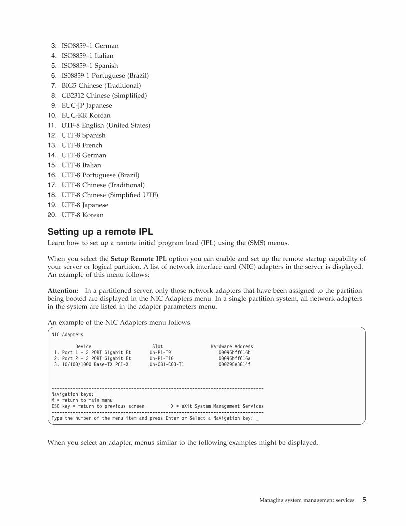
Setting up a remote IPLLearn how to set up a remote initial program load (IPL) using the (SMS) menus.
When you select the Setup Remote IPL option you can enable and set up the remote startup capability ofyour server or logical partition. A list of network interface card (NIC) adapters in the server is displayed.An example of this menu follows:
Attention: In a partitioned server, only those network adapters that have been assigned to the partitionbeing booted are displayed in the NIC Adapters menu. In a single partition system, all network adaptersin the system are listed in the adapter parameters menu.
An example of the NIC Adapters menu follows.
NIC Adapters
Device Slot Hardware Address1. Port 1 - 2 PORT Gigabit Et Un-P1-T9 00096bff616b2. Port 2 - 2 PORT Gigabit Et Un-P1-T10 00096bff616a3. 10/100/1000 Base-TX PCI-X Un-CB1-C03-T1 000295e3814f
--------------------------------------------------------------------------------Navigation keys:M = return to main menuESC key = return to previous screen X = eXit System Management Services--------------------------------------------------------------------------------Type the number of the menu item and press Enter or Select a Navigation key: _
When you select an adapter, menus similar to the following examples might be displayed.
Managing system management services 5

Select Internet Protocol Version.
1. IPv4 - Address Format 123.231.111.2222. IPv6 - Address Format 1234:5678:90ab:cdef:1234:5678:90ab:cdef
--------------------------------------------------------------------------------Navigation keys:M = return to main menuESC key = return to previous screen X = eXit System Management Services--------------------------------------------------------------------------------Type menu item number and press Enter or select Navigation key: _
Select Network ServiceNo alias : Port 1-IBM Host Ethernet Adapter: Un-P1-T6
1. BOOTP2. ISCSI
--------------------------------------------------------------------------------Navigation keys:M = return to main menuESC key = return to previous screen X = eXit System Management Services--------------------------------------------------------------------------------Type menu item number and press Enter or select Navigation key: _
Note: The menus depend on the selections you have made. For example, if IPv6 is chosen, the networkinterface card (NIC) might be configured for Trivial File Transfer Protocol (TFTP) boot. If IPv4 is chosen,the NIC might be configured for BOOTP.Related tasks:“Using system management services” on page 3Learn how the system management services (SMS) menus can help you manage your system.
Selecting the BOOTP or TFTP optionIf you select BOOTP or TFTP option, the adapter is set up (and the network parameters are entered) asusual. The Network Parameters menu is displayed.
After you select the BOOTP or TFTP option on the Select Network Service menu, the NetworkParameters menu is displayed. The menus and options change depending on whether IPv4 or IPv6 wasselected on the Select Internet Protocol Version menu. A menu similar to the following example isdisplayed.
Network Parameters
Port 1 - 2 PORT Gigabit Et Un-P1-T9 00096bff616b1. IP Parameters2. Adapter Parameters3. Ping Test4. Advanced Setup: BOOTP/TFTP
--------------------------------------------------------------------------------Navigation keys:M = return to main menuESC key = return to previous screen X = eXit System Management Services--------------------------------------------------------------------------------Type the number of the menu item and press Enter or Select a Navigation key: _
Selecting the IP (Internet Protocol) parameters option displays a menu similar to the following example.
6 Power Systems: Managing system management services

IP Parameters
Port 1 - 2 PORT Gigabit Et Un-P1-T9 00096bff616b1. Client IP Address [9.8.38.50]2. Server IP Address [9.8.38.51]3. Gateway IP Address [9.8.38.1]4. Subnet Mask [255.255.255.000]
--------------------------------------------------------------------------------Navigation keys:M = return to main menuESC key = return to previous screen X = eXit System Management Services--------------------------------------------------------------------------------Type the number of the menu item and press Enter or Select a Navigation key: _
To change IP parameters, type the number of the parameters for which you want to change the value.Entering IP parameters on this menu automatically updates the parameters on the ping test menu.
Select the Ping Test option from the Network Parameters menu to test the network connection of anadapter to a remote system. After you select the ping test option, the Ping Test menu is displayed.Perform a Ping test by selecting the configuration options.
Notes:
v After you start the ping test, it might take 60 seconds or longer to return a result.v After the ping test passes or fails, the firmware stops and waits for a key to be pressed before
continuing.
Select the Advanced Setup option from the Network Parameters menu to configure the BOOTP or TFTPboot parameters. For BOOTP, the values 5, 512, 5, 0 and 0 are the respective default values for thefollowing options.
Advanced Setup: BOOTP/TFTP
Port 1-IBM 2 PORT 1000 Base-SX PCI-X Adapter: U788D.001.23A0034-P1-T7
1. Bootp Retries 52. Bootp Blocksize 5123. TFTP Retries 54. VLAN Priority 05. VLAN ID 0
--------------------------------------------------------------------------------Navigation keys:M = return to main menuESC key = return to previous screen X = eXit System Management Services--------------------------------------------------------------------------------Type the number of the menu item and press Enter or Select a Navigation key: _
Select the VLAN Priority option from the Advanced Setup menu to set the VLAN priority, and select theVLAN ID option to set the VLAN ID.
Notes:
v The default setting of the VLAN Priority option is 0, but a decimal value in the range 0 - 7 can be setfor the frame priority.
v An error message is displayed if a value greater than 7 is entered, in which case the default value is setback to the VLAN Priority option.
v The default value for the VLAN ID option is 0 and is reserved, because this frame does not belong toany VLAN.
Managing system management services 7
v Values must be entered as a decimal numbers. Valid values for a VLAN ID must be in the range 1 -4094. If the VLAN ID option is set to 0, VLAN tagging is disabled.
v An error message is displayed if a decimal value greater than 4094 is entered, in which case the defaultvalue is set back to the VLAN ID option.
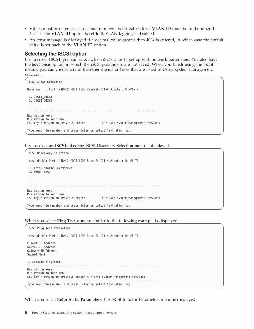
Selecting the ISCSI optionIf you select ISCSI, you can select which iSCSI alias to set up with network parameters. You also havethe boot once option, in which the iSCSI parameters are not saved. When you finish using the iSCSImenus, you can choose any of the other menus or tasks that are listed in Using system managementservices.
ISCSI Alias Selection
No alias : Port 1-IBM 2 PORT 1000 Base-SX PCI-X Adapter: Un-P1-T7
1. ISCSI_DISK12. ISCSI_DISK2
--------------------------------------------------------------------------------Navigation keys:M = return to main menuESC key = return to previous screen X = eXit System Management Services--------------------------------------------------------------------------------Type menu item number and press Enter or select Navigation key: _
If you select an ISCSI alias, the ISCSI Discovery Selection menu is displayed.
ISCSI Discovery Selection
iscsi_disk1: Port 1-IBM 2 PORT 1000 Base-SX PCI-X Adapter: Un-P1-T7
1. Enter Static Parameters.2. Ping Test.
--------------------------------------------------------------------------------Navigation keys:M = return to main menuESC key = return to previous screen X = eXit System Management Services--------------------------------------------------------------------------------Type menu item number and press Enter or select Navigation key: _
When you select Ping Test, a menu similar to the following example is displayed.
ISCSI Ping Test Parameters
iscsi_disk1: Port 1-IBM 2 PORT 1000 Base-SX PCI-X Adapter: Un-P1-T7
Client IP AddressServer IP AddressGateway IP AddressSubnet Mask
1. Execute ping test--------------------------------------------------------------------------------Navigation keys:M = return to main menuESC key = return to previous screen X = eXit System Management Services--------------------------------------------------------------------------------Type menu item number and press Enter or select Navigation key: _
When you select Enter Static Parameters, the ISCSI Initiator Parameters menu is displayed.
8 Power Systems: Managing system management services
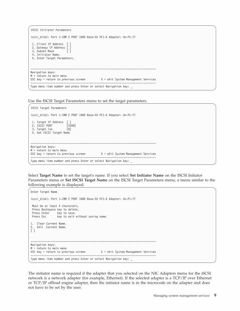
ISCSI Initiator Parameters
iscsi_disk1: Port 1-IBM 2 PORT 1000 Base-SX PCI-X Adapter: Un-P1-T7
1. Client IP Address [ ]2. Gateway IP Address [ ]3. Subnet Mask [ ]4. Initiator Name.5. Enter Target Parameters.
--------------------------------------------------------------------------------Navigation keys:M = return to main menuESC key = return to previous screen X = eXit System Management Services--------------------------------------------------------------------------------Type menu item number and press Enter or select Navigation key: _
Use the ISCSI Target Parameters menu to set the target parameters.
ISCSI Target Parameters
iscsi_disk1: Port 1-IBM 2 PORT 1000 Base-SX PCI-X Adapter: Un-P1-T7
1. Target IP Address [ ]2. ISCSI PORT [3260]3. Target lun [0]4. Set ISCSI Target Name
--------------------------------------------------------------------------------Navigation keys:M = return to main menuESC key = return to previous screen X = eXit System Management Services--------------------------------------------------------------------------------Type menu item number and press Enter or select Navigation key: _
Select Target Name to set the target's name. If you select Set Initiator Name on the ISCSI InitiatorParameters menu or Set ISCSI Target Name on the ISCSI Target Parameters menu, a menu similar to thefollowing example is displayed.
Enter Target Name
iscsi_disk1: Port 1-IBM 2 PORT 1000 Base-SX PCI-X Adapter: Un-P1-T7
Must be at least 4 characters.Press Backspace key to delete.Press Enter key to save.Press Esc key to exit without saving name.
1. Clear Current Name.2. Edit Current Name.[ ]
--------------------------------------------------------------------------------Navigation keys:M = return to main menuESC key = return to previous screen X = eXit System Management Services--------------------------------------------------------------------------------Type menu item number and press Enter or select Navigation key: _
The initiator name is required if the adapter that you selected on the NIC Adapters menu for the iSCSInetwork is a network adapter (for example, Ethernet). If the selected adapter is a TCP/IP over Ethernetor TCP/IP offload engine adapter, then the initiator name is in the microcode on the adapter and doesnot have to be set by the user.
Managing system management services 9
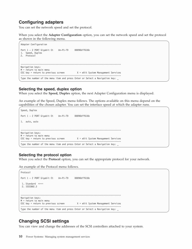
Configuring adaptersYou can set the network speed and set the protocol.
When you select the Adapter Configuration option, you can set the network speed and set the protocolas shown in the following menu.
Adapter Configuration
Port 1 - 2 PORT Gigabit Et Un-P1-T9 00096bff616b1. Speed, Duplex2. Protocol
--------------------------------------------------------------------------------Navigation keys:M = return to main menuESC key = return to previous screen X = eXit System Management Services--------------------------------------------------------------------------------Type the number of the menu item and press Enter or Select a Navigation key: _
Selecting the speed, duplex optionWhen you select the Speed, Duplex option, the next Adapter Configuration menu is displayed.
An example of the Speed, Duplex menu follows. The options available on this menu depend on thecapabilities of the chosen adapter. You can set the interface speed at which the adapter runs.
Speed, Duplex
Port 1 - 2 PORT Gigabit Et Un-P1-T9 00096bff616b
1. auto, auto
--------------------------------------------------------------------------------Navigation keys:M = return to main menuESC key = return to previous screen X = eXit System Management Services--------------------------------------------------------------------------------Type the number of the menu item and press Enter or Select a Navigation key: _
Selecting the protocol optionWhen you select the Protocol option, you can set the appropriate protocol for your network.
An example of the Protocol menu follows.
Protocol
Port 1 - 2 PORT Gigabit Et Un-P1-T9 00096bff616b
1. Standard <===2. IEEE802.3
--------------------------------------------------------------------------------Navigation keys:M = return to main menuESC key = return to previous screen X = eXit System Management Services--------------------------------------------------------------------------------Type the number of the menu item and press Enter or Select a Navigation key: _
Changing SCSI settingsYou can view and change the addresses of the SCSI controllers attached to your system.
10 Power Systems: Managing system management services

When you select the Change SCSI Settings option, you can view and change the addresses of the SCSIcontrollers attached to your system.
SCSI Utilities
1. Hardware Spin Up Delay2. Change SCSI Id
--------------------------------------------------------------------------------Navigation keys:M = return to main menuESC key = return to previous screen X = eXit System Management Services--------------------------------------------------------------------------------Type the number of the menu item and press Enter or Select a Navigation key: _
Selecting the consoleYou can select which console to use to display the SMS menus.
When you select the Select Console option, you can select which console to use to display the SMSmenus. This selection is only for the SMS menus and does not affect the console used by the operatingsystem.
Follow the instructions that are displayed on the console. The firmware automatically returns to the SMSmain menu after the console is chosen.
Note: If you do not change the console to another device before removing the current console, you mustreattach the current console to change your console selection.
Selecting boot optionsYou can install or boot a device, configure a boot device order, select the multiboot startup option, orselect the storage area network (SAN) zoning support option.
Selecting to install or boot a deviceOnly for the next boot, select a device from which to boot the operating system or install the operatingsystem. The boot list stored in nonvolatile random access memory (NVRAM) will not be changed.
Select the Select Install/Boot a Device option to view and set various options regarding the installationdevices and boot devices.
1. Select Install/Boot a Device2. Configure Boot Device Order3. Multiboot Startup [OFF]4. SAN Zoning Support
--------------------------------------------------------------------------------Navigation keys:M = return to main menuESC key = return to previous screen X = eXit System Management Services--------------------------------------------------------------------------------Type the number of the menu item and press Enter or Select a Navigation key: _
A menu similar to the following example is displayed.
Managing system management services 11

Select Device Type
1. Diskette2. Tape3. CD/DVD4. IDE5. Hard Drive6. Network7. List All Devices
--------------------------------------------------------------------------------Navigation keys:M = return to main menuESC key = return to previous screen X = eXit System Management Services--------------------------------------------------------------------------------Type the number of the menu item and press Enter or Select a Navigation key: _
If you select Hard Drive, a menu similar to the following example is displayed.
Select Hard Drive Type
1. SCSI2. SSA3. SAN4. SAS5. SATA6. USB7. IDE8. ISA9. List All Devices
--------------------------------------------------------------------------------Navigation keys:M = return to main menuESC key = return to previous screen X = eXit System Management Services--------------------------------------------------------------------------------Type the number of the menu item and press Enter or Select a Navigation key: _
If you select SCSI, for example, all of the SCSI adapters that are in the system, or assigned to the logicalpartition, are displayed on the next menu. Depending on the devices that are installed in your system, amenu similar to the following is displayed.
Version EM310_024SMS 1.6 (c) Copyright IBM Corp. 2000, 2005 All rights reserved.--------------------------------------------------------------------------------
Select Media Adapter
1. Un-P1-T14 /pci@80000002000000d/pci@2/pci1069,b166@1/scsi@02. Un-P1-T12 /pci@80000002000000f/pci@2,2/pci1069,b166@1/scsi@03. Un-P1-T13 /pci@80000002000000f/pci@2,2/pci1069,b166@1/scsi@14. List all devices
--------------------------------------------------------------------------------Navigation keys:M = return to main menuESC key = return to previous screen X = eXit System Management Services--------------------------------------------------------------------------------Type the number of the menu item and press Enter or Select a Navigation key: _
When you select an adapter, the next menu displays the bootable devices of the requested type that areattached to that adapter. In the following example, all of the bootable SCSI hard files that are attached tothe first adapter are listed.
12 Power Systems: Managing system management services

Version EM310_024SMS 1.6 (c) Copyright IBM Corp. 2000, 2005 All rights reserved.--------------------------------------------------------------------------------Select DeviceDevice Current DeviceNumber Position Name
1 1 SCSI 73407 MB Harddisk Un-P1-T14 /pci@80000002000000d/pci@2/pci1069,b166@1/scsi@0
--------------------------------------------------------------------------------Navigation keys:M = return to main menuESC key = return to previous screen X = eXit System Management Services--------------------------------------------------------------------------------Type the number of the menu item and press Enter or Select a Navigation key: _
You can now select the appropriate device for this installation or boot.
When a device is selected for installing the operating system, or to boot from, the Select Task menu mightbe used to retrieve more information about the device, or to boot from that device in normal mode orservice mode. The following is an example of this menu.
Select Task
SCSI 36401 MB Harddisk, part=2 (AIX 5.3.0)(loc=U788D.001.06A0034-P1-T10-L1-L0)
1. Information2. Normal Mode Boot3. Service Mode Boot
---------------------------------------------------------------------------------Navigation keys:M = return to main menuESC key = return to previous screen X = eXit System Management Services---------------------------------------------------------------------------------Type the number of the menu item and press Enter or Select a Navigation key: _
If you select either Normal Mode Boot or Service Mode Boot, the next menu asks, Are you sure? If youanswer yes, the device is booted in the appropriate mode. If you answer no, the firmware returns to theSelect Task menu.
Configuring boot device orderYou can view and change the customized boot list.
To minimize the search time for bootable devices, these menus follow this hierarchy:
device type > bus type > adapter > devices attached to the adapter
By selecting List All Devices from the Select Device Type menu or the Select Media Type menu, you canview all of the potentially bootable devices at one time. Only bootable hard disks are listed.
The List All Devices function can take a long time, or may be incomplete on a large system with manyI/O adapters and devices, such as large disk arrays. However, the following selection might reduce theoverall time required to scan for all of the devices because the scan is restricted to the selected adapter.
device type (for example, hard disk) > interface type (for example, SCSI) > specific adapter
Managing system management services 13

Select the Select Boot Devices option to view and change the customized boot list, which is the sequenceof devices read at startup.
Configure Boot Device Order
1. Select 1st Boot Device2. Select 2nd Boot Device3. Select 3rd Boot Device4. Select 4th Boot Device5. Select 5th Boot Device6. Display Current Setting7. Restore Default Setting
--------------------------------------------------------------------------------Navigation keys:M = return to main menuESC key = return to previous screen X = eXit System Management Services--------------------------------------------------------------------------------Type the number of the menu item and press Enter or Select a Navigation key: _
When you select any of the options 1 - 5, the Select Device Type menu is displayed.
Select Device Type
1. Diskette2. Tape3. CD/DVD4. IDE5. Hard Drive6. Network7. List All Devices
--------------------------------------------------------------------------------Navigation keys:M = return to main menuESC key = return to previous screen X = eXit System Management Services--------------------------------------------------------------------------------Type the number of the menu item and press Enter or Select a Navigation key: _
By selecting List All Devices from the Select Device Type menu or the Select Media Type menu, you canview all of the potentially bootable devices at one time. Only bootable hard disks are listed. The List AllDevices function can take a long time or may be incomplete on a large system with many I/O adaptersand devices, such as large disk arrays. However, the following selection might reduce the overall timerequired to scan for all of the devices because the scan is restricted to the selected adapter: device type(for example, hard disk) > interface type (for example, SCSI) > specific adapter.
When you select a device type, such as option 5, a Select Media Type menu is displayed. The following isan example of that menu.
14 Power Systems: Managing system management services
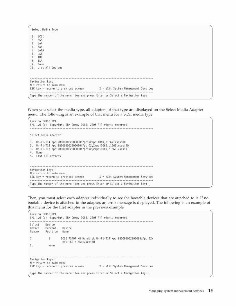
Select Media Type
1. SCSI2. SSA3. SAN4. SAS5. SATA6. USB7. IDE8. ISA9. None
10. List All Devices
--------------------------------------------------------------------------------Navigation keys:M = return to main menuESC key = return to previous screen X = eXit System Management Services--------------------------------------------------------------------------------Type the number of the menu item and press Enter or Select a Navigation key: _
When you select the media type, all adapters of that type are displayed on the Select Media Adaptermenu. The following is an example of that menu for a SCSI media type.
Version EM310_024SMS 1.6 (c) Copyright IBM Corp. 2000, 2005 All rights reserved.--------------------------------------------------------------------------------
Select Media Adapter
1. Un-P1-T14 /pci@80000002000000d/pci@2/pci1069,b166@1/scsi@02. Un-P1-T12 /pci@80000002000000f/pci@2,2/pci1069,b166@1/scsi@03. Un-P1-T13 /pci@80000002000000f/pci@2,2/pci1069,b166@1/scsi@14. None5. List all devices
--------------------------------------------------------------------------------Navigation keys:M = return to main menuESC key = return to previous screen X = eXit System Management Services--------------------------------------------------------------------------------Type the number of the menu item and press Enter or Select a Navigation key: _
Then, you must select each adapter individually to see the bootable devices that are attached to it. If nobootable device is attached to the adapter, an error message is displayed. The following is an example ofthis menu for the first adapter in the previous example.
Version EM310_024SMS 1.6 (c) Copyright IBM Corp. 2000, 2005 All rights reserved.--------------------------------------------------------------------------------Select DeviceDevice Current DeviceNumber Position Name
1 1 SCSI 73407 MB Harddisk Un-P1-T14 /pci@80000002000000d/pci@2/pci1069,b166@1/scsi@0
2. None
--------------------------------------------------------------------------------Navigation keys:M = return to main menuESC key = return to previous screen X = eXit System Management Services--------------------------------------------------------------------------------Type the number of the menu item and press Enter or Select a Navigation key: _
Managing system management services 15

When you select a device type, you can view detailed information about the device or set the devicelocation in the boot list from the Select Task menu. (Note that only bootable disks are listed.) Thefollowing is an example of the menu for a hard disk.
Select Task
SCSI 36401 MB Harddisk Un-P1-T14 /pci@80000002000000d/pci@2/pci1069,b166@1/scsi@01. Information2. Set Boot Sequence: Configure as 1st Boot Device
---------------------------------------------------------------------------------Navigation keys:M = return to main menuESC key = return to previous screen X = eXit System Management Services---------------------------------------------------------------------------------Type the number of the menu item and press Enter or Select a Navigation key: _
Selecting Information displays a menu similar to the following for a hard disk.
Device Information/pci@8000000200000dd/pci@2/pci1069,b166@1/scsi@1/sd@5,0
: (Bootable)DEVICE : SCSI 73407 MB Harddisk Un-P1-T14 /pci@80000002000000d/pci@2/
pci1069,b166@1/scsi@0NAME : sdDEVICE-TYPE : block
Parent InformationIBM,FW-ADAPTER-NAME: Ultra-320NAME : scsiDEVICE-TYPE : scsi-2
---------------------------------------------------------------------------------Navigation keys:M = return to main menuESC key = return to previous screen X = eXit System Management Services---------------------------------------------------------------------------------Type the number of the menu item and press Enter or Select a Navigation key: _
Select the Display Current Settings to display the current setting of the customized boot list.
An example of this menu, with one device in the boot list, follows.
Current Boot Sequence
1. SCSI 73407 MB Harddisk Un-P1-T14 /pci@80000002000000d/pci@2/pci1069,b166@1/scsi@02. None3. None4. None5. None
------------------------------------------------------------------------------------Navigation keys:M = return to main menuESC key = return to previous screen X = eXit System Management Services------------------------------------------------------------------------------------Type the number of the menu item and press Enter or Select a Navigation key: _
Select the Restore Default Settings option to restore the boot list to the default boot list.
The default boot list varies depending on the devices that are installed in the system. The default boot listis as follows:
16 Power Systems: Managing system management services

1. Primary diskette drive (if installed)2. Optical drive (if installed)3. Tape drive (if installed)4. Hard disk drive (if installed)5. Network adapter
Multiboot startupThe multiboot startup flag, if enabled, stops the system at the SMS menus every time the system starts. Itallows you to start the system from another device.
SAN zoning supportBy using the storage area network (SAN) zoning option, you can perform SAN zoning for all FibreChannel adapters, which includes the virtual Fibre Channel adapters that are assigned to the partitionbeing booted.
When an adapter is selected, the selected adapter is opened and remains open during the zoning activity,which ensures that the switch can determine the worldwide port number and worldwide node name ofthe adapter.
Select the SAN Zoning Support option. A menu similar to the following example is displayed.
PowerPC FirmwareVersion ZL740_052SMS 1.7 (c) Copyright IBM Corp. 2000,2008 All rights reserved.-------------------------------------------------------------------------------
Select Media Adapter
1. U78AA.001.WIH0029-P1-C7-T1 /pci@80000002000000d/fibre-channel@0
--------------------------------------------------------------------------------Navigation keys:M = return to main menuESC key = return to previous screen X = eXit System Management Services--------------------------------------------------------------------------------Type the number of the menu item and press Enter or Select a Navigation key: _
When an adapter is selected, a menu similar to the following example is displayed.
.---------------------------------------------------------------------.| The selected adapter has been opened. || Zoning of attached disks may now be possible. || Press any key to close the adapter and return to the previous menu. |`-----------------------------------------------------------------------’
Power-on self-test keysThe power-on self-test (POST) keys can start services or initiate service mode boots used for configuringthe system and diagnosing problems.
After power is turned on and before the operating system is loaded, the system does a power-on self-test(POST). This test performs checks to ensure that the hardware is functioning correctly before theoperating system is loaded. During the POST, a POST screen is displayed, and POST indicators appear onthe firmware console (if one is connected).
Managing system management services 17
The POST keys, if pressed after the keyboard POST indicator is displayed and before the last POSTindicator speaker is displayed, cause the system to start services or to initiate service mode boots used forconfiguring the system and diagnosing problems.
Note: The program function keys (F1-F12) on a keyboard attached to the service processor are not usedand are ignored. After the keyboard POST indicator is displayed, you must use the numeric numberkeys.
Numeric 1 key
The numeric 1 key, when pressed during POST, starts the system management services interface.
Numeric 5 key
The numeric 5 key, when pressed during POST, initiates a system boot in service mode using the defaultservice mode boot list.
This mode attempts to boot from the first device of each type found in the list. It does not search forother bootable devices of that type if the first device is not bootable. Instead, it continues to the nextdevice type in the list.
The default boot sequence is:1. Diskette (if installed)2. CD-ROM (if installed)3. Tape drive (if installed)4. Hard file5. Network
Numeric 6 key
The numeric 6 key works like the numeric 5 key.
Exiting system management servicesAfter you finish using the SMS menus, type x (for exit) to boot your system.
18 Power Systems: Managing system management services
Notices
This information was developed for products and services offered in the U.S.A.
The manufacturer may not offer the products, services, or features discussed in this document in othercountries. Consult the manufacturer's representative for information on the products and servicescurrently available in your area. Any reference to the manufacturer's product, program, or service is notintended to state or imply that only that product, program, or service may be used. Any functionallyequivalent product, program, or service that does not infringe any intellectual property right of themanufacturer may be used instead. However, it is the user's responsibility to evaluate and verify theoperation of any product, program, or service.
The manufacturer may have patents or pending patent applications covering subject matter described inthis document. The furnishing of this document does not grant you any license to these patents. You cansend license inquiries, in writing, to the manufacturer.
The following paragraph does not apply to the United Kingdom or any other country where suchprovisions are inconsistent with local law: THIS PUBLICATION IS PROVIDED “AS IS” WITHOUTWARRANTY OF ANY KIND, EITHER EXPRESS OR IMPLIED, INCLUDING, BUT NOT LIMITED TO,THE IMPLIED WARRANTIES OF NON-INFRINGEMENT, MERCHANTABILITY OR FITNESS FOR APARTICULAR PURPOSE. Some states do not allow disclaimer of express or implied warranties in certaintransactions, therefore, this statement may not apply to you.
This information could include technical inaccuracies or typographical errors. Changes are periodicallymade to the information herein; these changes will be incorporated in new editions of the publication.The manufacturer may make improvements and/or changes in the product(s) and/or the program(s)described in this publication at any time without notice.
Any references in this information to websites not owned by the manufacturer are provided forconvenience only and do not in any manner serve as an endorsement of those websites. The materials atthose websites are not part of the materials for this product and use of those websites is at your own risk.
The manufacturer may use or distribute any of the information you supply in any way it believesappropriate without incurring any obligation to you.
Any performance data contained herein was determined in a controlled environment. Therefore, theresults obtained in other operating environments may vary significantly. Some measurements may havebeen made on development-level systems and there is no guarantee that these measurements will be thesame on generally available systems. Furthermore, some measurements may have been estimated throughextrapolation. Actual results may vary. Users of this document should verify the applicable data for theirspecific environment.
Information concerning products not produced by this manufacturer was obtained from the suppliers ofthose products, their published announcements or other publicly available sources. This manufacturer hasnot tested those products and cannot confirm the accuracy of performance, compatibility or any otherclaims related to products not produced by this manufacturer. Questions on the capabilities of productsnot produced by this manufacturer should be addressed to the suppliers of those products.
All statements regarding the manufacturer's future direction or intent are subject to change or withdrawalwithout notice, and represent goals and objectives only.
The manufacturer's prices shown are the manufacturer's suggested retail prices, are current and aresubject to change without notice. Dealer prices may vary.
© Copyright IBM Corp. 2010, 2012 19

This information is for planning purposes only. The information herein is subject to change before theproducts described become available.
This information contains examples of data and reports used in daily business operations. To illustratethem as completely as possible, the examples include the names of individuals, companies, brands, andproducts. All of these names are fictitious and any similarity to the names and addresses used by anactual business enterprise is entirely coincidental.
If you are viewing this information in softcopy, the photographs and color illustrations may not appear.
The drawings and specifications contained herein shall not be reproduced in whole or in part without thewritten permission of the manufacturer.
The manufacturer has prepared this information for use with the specific machines indicated. Themanufacturer makes no representations that it is suitable for any other purpose.
The manufacturer's computer systems contain mechanisms designed to reduce the possibility ofundetected data corruption or loss. This risk, however, cannot be eliminated. Users who experienceunplanned outages, system failures, power fluctuations or outages, or component failures must verify theaccuracy of operations performed and data saved or transmitted by the system at or near the time of theoutage or failure. In addition, users must establish procedures to ensure that there is independent dataverification before relying on such data in sensitive or critical operations. Users should periodically checkthe manufacturer's support websites for updated information and fixes applicable to the system andrelated software.
Homologation statement
This product may not be certified in your country for connection by any means whatsoever to interfacesof public telecommunications networks. Further certification may be required by law prior to making anysuch connection. Contact an IBM representative or reseller for any questions.
TrademarksIBM, the IBM logo, and ibm.com are trademarks or registered trademarks of International BusinessMachines Corp., registered in many jurisdictions worldwide. Other product and service names might betrademarks of IBM or other companies. A current list of IBM trademarks is available on the web atCopyright and trademark information at www.ibm.com/legal/copytrade.shtml.
Linux is a registered trademark of Linus Torvalds in the United States, other countries, or both.
Electronic emission noticesWhen attaching a monitor to the equipment, you must use the designated monitor cable and anyinterference suppression devices supplied with the monitor.
Class A NoticesThe following Class A statements apply to the IBM servers that contain the POWER7 processor and itsfeatures unless designated as electromagnetic compatibility (EMC) Class B in the feature information.
Federal Communications Commission (FCC) statement
Note: This equipment has been tested and found to comply with the limits for a Class A digital device,pursuant to Part 15 of the FCC Rules. These limits are designed to provide reasonable protection againstharmful interference when the equipment is operated in a commercial environment. This equipmentgenerates, uses, and can radiate radio frequency energy and, if not installed and used in accordance with
20 Power Systems: Managing system management services

the instruction manual, may cause harmful interference to radio communications. Operation of thisequipment in a residential area is likely to cause harmful interference, in which case the user will berequired to correct the interference at his own expense.
Properly shielded and grounded cables and connectors must be used in order to meet FCC emissionlimits. IBM is not responsible for any radio or television interference caused by using other thanrecommended cables and connectors or by unauthorized changes or modifications to this equipment.Unauthorized changes or modifications could void the user's authority to operate the equipment.
This device complies with Part 15 of the FCC rules. Operation is subject to the following two conditions:(1) this device may not cause harmful interference, and (2) this device must accept any interferencereceived, including interference that may cause undesired operation.
Industry Canada Compliance Statement
This Class A digital apparatus complies with Canadian ICES-003.
Avis de conformité à la réglementation d'Industrie Canada
Cet appareil numérique de la classe A est conforme à la norme NMB-003 du Canada.
European Community Compliance Statement
This product is in conformity with the protection requirements of EU Council Directive 2004/108/EC onthe approximation of the laws of the Member States relating to electromagnetic compatibility. IBM cannotaccept responsibility for any failure to satisfy the protection requirements resulting from anon-recommended modification of the product, including the fitting of non-IBM option cards.
This product has been tested and found to comply with the limits for Class A Information TechnologyEquipment according to European Standard EN 55022. The limits for Class A equipment were derived forcommercial and industrial environments to provide reasonable protection against interference withlicensed communication equipment.
European Community contact:IBM Deutschland GmbHTechnical Regulations, Department M372IBM-Allee 1, 71139 Ehningen, GermanyTele: +49 7032 15 2941email: [email protected]
Warning: This is a Class A product. In a domestic environment, this product may cause radiointerference, in which case the user may be required to take adequate measures.
VCCI Statement - Japan
The following is a summary of the VCCI Japanese statement in the box above:
Notices 21

This is a Class A product based on the standard of the VCCI Council. If this equipment is used in adomestic environment, radio interference may occur, in which case, the user may be required to takecorrective actions.
Japanese Electronics and Information Technology Industries Association (JEITA)Confirmed Harmonics Guideline (products less than or equal to 20 A per phase)
Japanese Electronics and Information Technology Industries Association (JEITA)Confirmed Harmonics Guideline with Modifications (products greater than 20 A perphase)
Electromagnetic Interference (EMI) Statement - People's Republic of China
Declaration: This is a Class A product. In a domestic environment this product may cause radiointerference in which case the user may need to perform practical action.
Electromagnetic Interference (EMI) Statement - Taiwan
The following is a summary of the EMI Taiwan statement above.
Warning: This is a Class A product. In a domestic environment this product may cause radio interferencein which case the user will be required to take adequate measures.
IBM Taiwan Contact Information:
22 Power Systems: Managing system management services

Electromagnetic Interference (EMI) Statement - Korea
Germany Compliance Statement
Deutschsprachiger EU Hinweis: Hinweis für Geräte der Klasse A EU-Richtlinie zurElektromagnetischen Verträglichkeit
Dieses Produkt entspricht den Schutzanforderungen der EU-Richtlinie 2004/108/EG zur Angleichung derRechtsvorschriften über die elektromagnetische Verträglichkeit in den EU-Mitgliedsstaaten und hält dieGrenzwerte der EN 55022 Klasse A ein.
Um dieses sicherzustellen, sind die Geräte wie in den Handbüchern beschrieben zu installieren und zubetreiben. Des Weiteren dürfen auch nur von der IBM empfohlene Kabel angeschlossen werden. IBMübernimmt keine Verantwortung für die Einhaltung der Schutzanforderungen, wenn das Produkt ohneZustimmung von IBM verändert bzw. wenn Erweiterungskomponenten von Fremdherstellern ohneEmpfehlung von IBM gesteckt/eingebaut werden.
EN 55022 Klasse A Geräte müssen mit folgendem Warnhinweis versehen werden:"Warnung: Dieses ist eine Einrichtung der Klasse A. Diese Einrichtung kann im WohnbereichFunk-Störungen verursachen; in diesem Fall kann vom Betreiber verlangt werden, angemesseneMaßnahmen zu ergreifen und dafür aufzukommen."
Deutschland: Einhaltung des Gesetzes über die elektromagnetische Verträglichkeit von Geräten
Dieses Produkt entspricht dem “Gesetz über die elektromagnetische Verträglichkeit von Geräten(EMVG)“. Dies ist die Umsetzung der EU-Richtlinie 2004/108/EG in der Bundesrepublik Deutschland.
Zulassungsbescheinigung laut dem Deutschen Gesetz über die elektromagnetische Verträglichkeit vonGeräten (EMVG) (bzw. der EMC EG Richtlinie 2004/108/EG) für Geräte der Klasse A
Dieses Gerät ist berechtigt, in Übereinstimmung mit dem Deutschen EMVG das EG-Konformitätszeichen- CE - zu führen.
Notices 23

Verantwortlich für die Einhaltung der EMV Vorschriften ist der Hersteller:International Business Machines Corp.New Orchard RoadArmonk, New York 10504Tel: 914-499-1900
Der verantwortliche Ansprechpartner des Herstellers in der EU ist:IBM Deutschland GmbHTechnical Regulations, Abteilung M372IBM-Allee 1, 71139 Ehningen, GermanyTel: +49 7032 15 2941email: [email protected]
Generelle Informationen:
Das Gerät erfüllt die Schutzanforderungen nach EN 55024 und EN 55022 Klasse A.
Electromagnetic Interference (EMI) Statement - Russia
Class B NoticesThe following Class B statements apply to features designated as electromagnetic compatibility (EMC)Class B in the feature installation information.
Federal Communications Commission (FCC) statement
This equipment has been tested and found to comply with the limits for a Class B digital device,pursuant to Part 15 of the FCC Rules. These limits are designed to provide reasonable protection againstharmful interference in a residential installation.
This equipment generates, uses, and can radiate radio frequency energy and, if not installed and used inaccordance with the instructions, may cause harmful interference to radio communications. However,there is no guarantee that interference will not occur in a particular installation.
If this equipment does cause harmful interference to radio or television reception, which can bedetermined by turning the equipment off and on, the user is encouraged to try to correct the interferenceby one or more of the following measures:v Reorient or relocate the receiving antenna.v Increase the separation between the equipment and receiver.v Connect the equipment into an outlet on a circuit different from that to which the receiver is
connected.v Consult an IBM-authorized dealer or service representative for help.
Properly shielded and grounded cables and connectors must be used in order to meet FCC emissionlimits. Proper cables and connectors are available from IBM-authorized dealers. IBM is not responsible for
24 Power Systems: Managing system management services

any radio or television interference caused by unauthorized changes or modifications to this equipment.Unauthorized changes or modifications could void the user's authority to operate this equipment.
This device complies with Part 15 of the FCC rules. Operation is subject to the following two conditions:(1) this device may not cause harmful interference, and (2) this device must accept any interferencereceived, including interference that may cause undesired operation.
Industry Canada Compliance Statement
This Class B digital apparatus complies with Canadian ICES-003.
Avis de conformité à la réglementation d'Industrie Canada
Cet appareil numérique de la classe B est conforme à la norme NMB-003 du Canada.
European Community Compliance Statement
This product is in conformity with the protection requirements of EU Council Directive 2004/108/EC onthe approximation of the laws of the Member States relating to electromagnetic compatibility. IBM cannotaccept responsibility for any failure to satisfy the protection requirements resulting from anon-recommended modification of the product, including the fitting of non-IBM option cards.
This product has been tested and found to comply with the limits for Class B Information TechnologyEquipment according to European Standard EN 55022. The limits for Class B equipment were derived fortypical residential environments to provide reasonable protection against interference with licensedcommunication equipment.
European Community contact:IBM Deutschland GmbHTechnical Regulations, Department M372IBM-Allee 1, 71139 Ehningen, GermanyTele: +49 7032 15 2941email: [email protected]
VCCI Statement - Japan
Japanese Electronics and Information Technology Industries Association (JEITA)Confirmed Harmonics Guideline (products less than or equal to 20 A per phase)
Notices 25

Japanese Electronics and Information Technology Industries Association (JEITA)Confirmed Harmonics Guideline with Modifications (products greater than 20 A perphase)
IBM Taiwan Contact Information
Electromagnetic Interference (EMI) Statement - Korea
Germany Compliance Statement
Deutschsprachiger EU Hinweis: Hinweis für Geräte der Klasse B EU-Richtlinie zurElektromagnetischen Verträglichkeit
Dieses Produkt entspricht den Schutzanforderungen der EU-Richtlinie 2004/108/EG zur Angleichung derRechtsvorschriften über die elektromagnetische Verträglichkeit in den EU-Mitgliedsstaaten und hält dieGrenzwerte der EN 55022 Klasse B ein.
Um dieses sicherzustellen, sind die Geräte wie in den Handbüchern beschrieben zu installieren und zubetreiben. Des Weiteren dürfen auch nur von der IBM empfohlene Kabel angeschlossen werden. IBMübernimmt keine Verantwortung für die Einhaltung der Schutzanforderungen, wenn das Produkt ohneZustimmung von IBM verändert bzw. wenn Erweiterungskomponenten von Fremdherstellern ohneEmpfehlung von IBM gesteckt/eingebaut werden.
Deutschland: Einhaltung des Gesetzes über die elektromagnetische Verträglichkeit von Geräten
Dieses Produkt entspricht dem “Gesetz über die elektromagnetische Verträglichkeit von Geräten(EMVG)“. Dies ist die Umsetzung der EU-Richtlinie 2004/108/EG in der Bundesrepublik Deutschland.
Zulassungsbescheinigung laut dem Deutschen Gesetz über die elektromagnetische Verträglichkeit vonGeräten (EMVG) (bzw. der EMC EG Richtlinie 2004/108/EG) für Geräte der Klasse B
26 Power Systems: Managing system management services

Dieses Gerät ist berechtigt, in Übereinstimmung mit dem Deutschen EMVG das EG-Konformitätszeichen- CE - zu führen.
Verantwortlich für die Einhaltung der EMV Vorschriften ist der Hersteller:International Business Machines Corp.New Orchard RoadArmonk, New York 10504Tel: 914-499-1900
Der verantwortliche Ansprechpartner des Herstellers in der EU ist:IBM Deutschland GmbHTechnical Regulations, Abteilung M372IBM-Allee 1, 71139 Ehningen, GermanyTel: +49 7032 15 2941email: [email protected]
Generelle Informationen:
Das Gerät erfüllt die Schutzanforderungen nach EN 55024 und EN 55022 Klasse B.
Terms and conditionsPermissions for the use of these publications are granted subject to the following terms and conditions.
Applicability: These terms and conditions are in addition to any terms of use for the IBM website.
Personal Use: You may reproduce these publications for your personal, noncommercial use provided thatall proprietary notices are preserved. You may not distribute, display or make derivative works of thesepublications, or any portion thereof, without the express consent of IBM.
Commercial Use: You may reproduce, distribute and display these publications solely within yourenterprise provided that all proprietary notices are preserved. You may not make derivative works ofthese publications, or reproduce, distribute or display these publications or any portion thereof outsideyour enterprise, without the express consent of IBM.
Rights: Except as expressly granted in this permission, no other permissions, licenses or rights aregranted, either express or implied, to the Publications or any information, data, software or otherintellectual property contained therein.
IBM reserves the right to withdraw the permissions granted herein whenever, in its discretion, the use ofthe publications is detrimental to its interest or, as determined by IBM, the above instructions are notbeing properly followed.
You may not download, export or re-export this information except in full compliance with all applicablelaws and regulations, including all United States export laws and regulations.
IBM MAKES NO GUARANTEE ABOUT THE CONTENT OF THESE PUBLICATIONS. THEPUBLICATIONS ARE PROVIDED "AS-IS" AND WITHOUT WARRANTY OF ANY KIND, EITHEREXPRESSED OR IMPLIED, INCLUDING BUT NOT LIMITED TO IMPLIED WARRANTIES OFMERCHANTABILITY, NON-INFRINGEMENT, AND FITNESS FOR A PARTICULAR PURPOSE.
Notices 27

28 Power Systems: Managing system management services


����
Printed in USA