Embed Size (px)
Citation preview
Asian Power Electronics Journal, Vol. 8, No. 3, Dec 2014
80
Power Transfer Capability Improvement to HVDC
Transmission System using Artificial Neural Network and
Inference System (ANFIS) Controller
M. Ramesh 1
A. Jaya Laxmi 2
Abstract–High Voltage Direct Current (HVDC)
Transmission systems traditionally employ PI controllers
with fixed proportional (P) and integral (I) gains Kp and Ki
respectively. Although such controllers are robust and simple,
they are not easily optimized to obtain the best performance
under all conditions. In the field of intelligent control systems,
fuzzy logic control and artificial neural network based
control are the two most popular control methodologies
being used. Neuro-fuzzy systems, as the name suggests
combine ANNs and fuzzy logic into one system. The aim of
such a combination is to inherit advantages of both the
intelligent control techniques and shunt out their individual
disadvantages. The CIGRÉ model as one of the conventional
methods has been studied and new complementary
characteristics have been added to improve its stability and
damping rate of voltage and current oscillations during the
disturbance in the AC Systems and to increase the efficiency
of the proposed model.
Keywords–HVDC transmission, CIGRÉ Benchmark model,
faults in HVDC system, proportional integral (PI) Controller,
ANFIS controller.
I. INTRODUCTION
High Voltage Direct Current (HVDC) Transmission is the
preferred method for bulk Transmission of power over
long distances [1]. HVDC System is a mature Technology
[2], starting from mercury-arc to thyristors and presently
to IGBT and IGCT valves, from conventional PI
Controllers to more advanced Control Techniques. Further
work needs to be done particularly on the Control aspects
to further improve the Transmission performance and
efficiency of such Systems. The performance of these
systems depends on the control method being used.
Furthermore, the control of a HVDC System remains a
formidable challenge because of various factors such as
changes in system conditions, converter Transformer
saturation characteristics, presence of AC/DC filters, and
the generation of harmonics by converter units which
makes the HVDC System highly complex and non-linear
[3]. Since fuzzy logic uses intuitive rules for the control of
the system, a detailed system model is not required. This
makes Fuzzy Logic well-suited for use with complex and
nonlinear systems, such as HVDC Systems. Earlier
research on the use of Fuzzy Logic to tune the PI
Controller parameters employed constant triangular
The paper first received 10 June 14 and in revised form 28 Dec 2014.
Digital Ref: APEJ_2014-06-0439 1 Associate Professor &HOD, EEE Dept, Medak College of Engineering
and Technlogy, KondapakMedakDist, Research Scholar, EEE Dept.,
JNTU, Anantapur-515002, Andhra Pradesh, India. E-mail: Marpuramesh223@ gmail.com 2 Professor, Dept. of EEE & Coordinator Centre for Energy
Studies, ,Jawaharlal Nehru Technological University, Hyderabad, College of Engineering, Kukatpally, Hyderabad-500085, Telangana, India. Email:[email protected]
Membership functions [4]–[7]. The past work generally
concluded that fuzzy logic could improve the performance
of HVDC systems under various fault conditions or
operating point changes, by decreasing the number of
commutation failures, improving the commutation margin,
or dampening oscillations.
The use of properly-designed neuro-fuzzy logic controllers
has been widely shown to provide at least marginal
improvement in the operation of HVDC systems compared
to the use of conventional constant-parameter PI
controllers [4]–[9]. This is explained by the fact that the
tuning of constant-parameter PI controllers is a
compromise between the speed of response and stability
after small disturbances, and the robustness to tolerate
large signal disturbances due to faults.
II. HVDC TEST SYSTEM
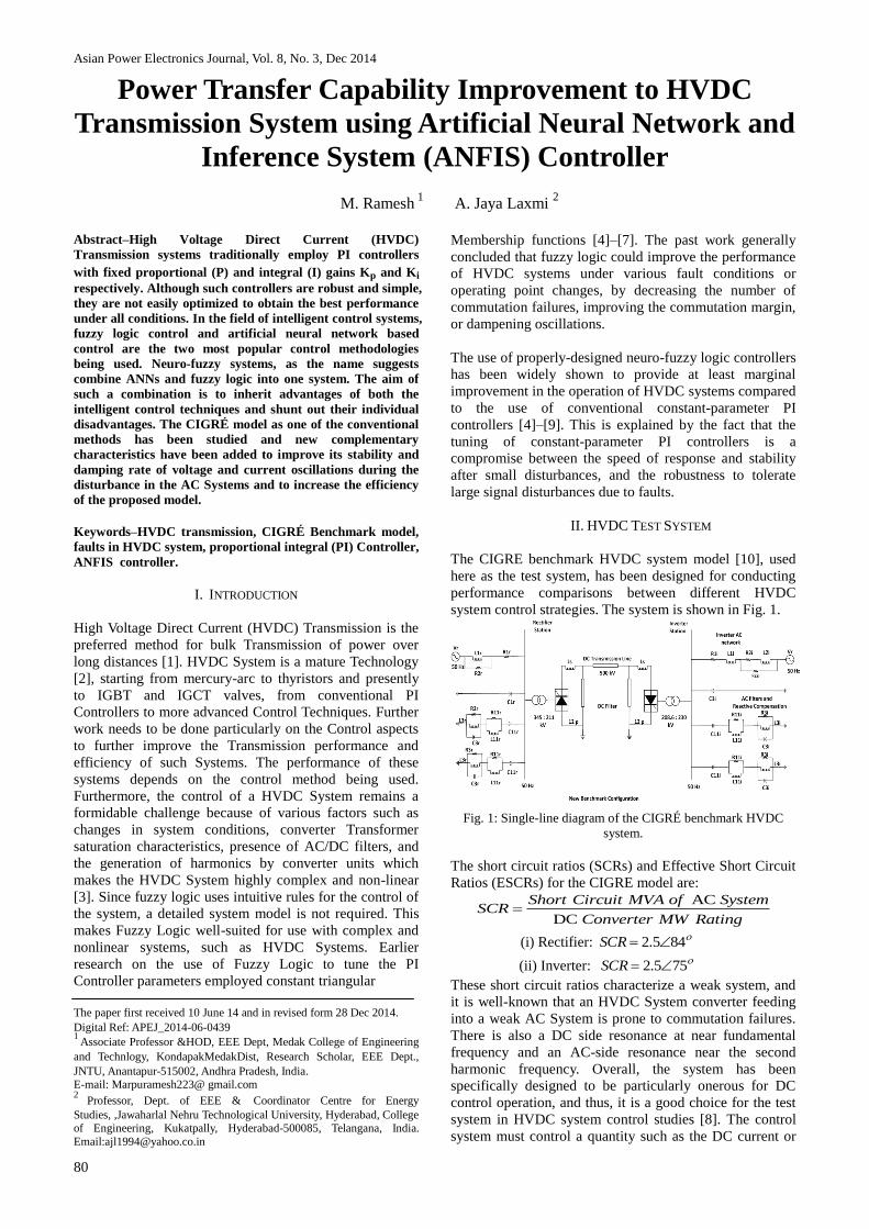
The CIGRE benchmark HVDC system model [10], used
here as the test system, has been designed for conducting
performance comparisons between different HVDC
system control strategies. The system is shown in Fig. 1.
Fig. 1: Single-line diagram of the CIGRÉ benchmark HVDC
system.
The short circuit ratios (SCRs) and Effective Short Circuit
Ratios (ESCRs) for the CIGRE model are:
AC
DC
Short Circuit MVA of System
ConvertSC
er MW R gR
atin
(i) Rectifier: 845.2 SCR
(ii) Inverter: 755.2 SCR
These short circuit ratios characterize a weak system, and
it is well-known that an HVDC System converter feeding
into a weak AC System is prone to commutation failures.
There is also a DC side resonance at near fundamental
frequency and an AC-side resonance near the second
harmonic frequency. Overall, the system has been
specifically designed to be particularly onerous for DC
control operation, and thus, it is a good choice for the test
system in HVDC system control studies [8]. The control
system must control a quantity such as the DC current or
M. Ramesh et. al: Power Transfer Capability Improvement to…
81
transmitted power, ensure stable operation in the presence
of small system disturbances, and minimize the
consequences of large disturbances or faults. To obtain
these objectives while consuming minimum reactive
power, the firing angles must be minimized [11]. The
rectifier operates under constant current (CC) control to
control the DC current and the inverter usually operates
under constant extinction angle (CEA) control to regulate
the DC voltage. For nominal conditions, the CEA control
ensures the extinction angle stays at its nominal value of
150, resulting in small reactive power consumption while
providing ample commutation margin to prevent
commutation failures. In a two terminal HVDC System,
the current margin control method is normally utilized
whereby the rectifier is kept in current control (CC) and
the inverter is in constant extinction angle (CEA) control.
An error signal, Ie, which is the difference between the
reference current, Id, and the measured current, Id, from
the system, is fed to the PI-controller. The error output of
the controller is acted upon by the PI gains to provide the
required alpha order for the HVDC converter. Due to
uncertainties in system parameters, the optimal choice of
gains is quite difficult. Proportional Integral (PI)
controllers are commonly used in HVDC System in
addition to AI controllers. A mathematical model of the
real plant is required for the controller design with
conventional methods. The difficulty of identifying the
accurate parameters for a complex nonlinear and time-
varying nature of real plants may render, in many cases,
the fine tuning of parameters which is time consuming.
Fig. 2 shows the structure of PI controller.
Fig. 2: Structure of PI controller.
III. ARTIFICIAL NEURAL NETWORK AND INFERENCE
SYSTEM CONTROLLER (ANFIS)
Previously, control techniques assumed a fixed
mathematical model of the plant but since HVDC systems
are highly uncertain, obtaining an accurate mathematical
model of the plant is not possible. Consequently, a lot of
research is being conducted in the application of
intelligent control techniques such as fuzzy logic, neural
networks and genetic algorithms to the control of HVDC
systems. Fuzzy logic (FL) based controllers have been
successful in improving the performance of the HVDC
system [11] ,However a combination of fuzzy logic and
artificial neural networks (ANNs) were used. Artificial
Neural Network and Inference System
(ANFIS) is developed from sugeno-type fuzzy inference
system (FIS) for effective data processing. The
development is a simple data learning technique by using
configuration of neuro-fuzzy model with hybrid learning
rule. FIS processes a given input mapping to get a target
output. This process involves membership function, fuzzy
logic operators and if-then rules. It has multiple inputs and
a single output with the capability in handling highly non-
linear functions and predicting future value of a chaotic
time series. Compared to the capabilities of the approaches
such as cascaded-correlation ANN, back propagation
ANN, sixth-order polynomial and other earlier methods,
the result obtained from the ANFIS gives a better
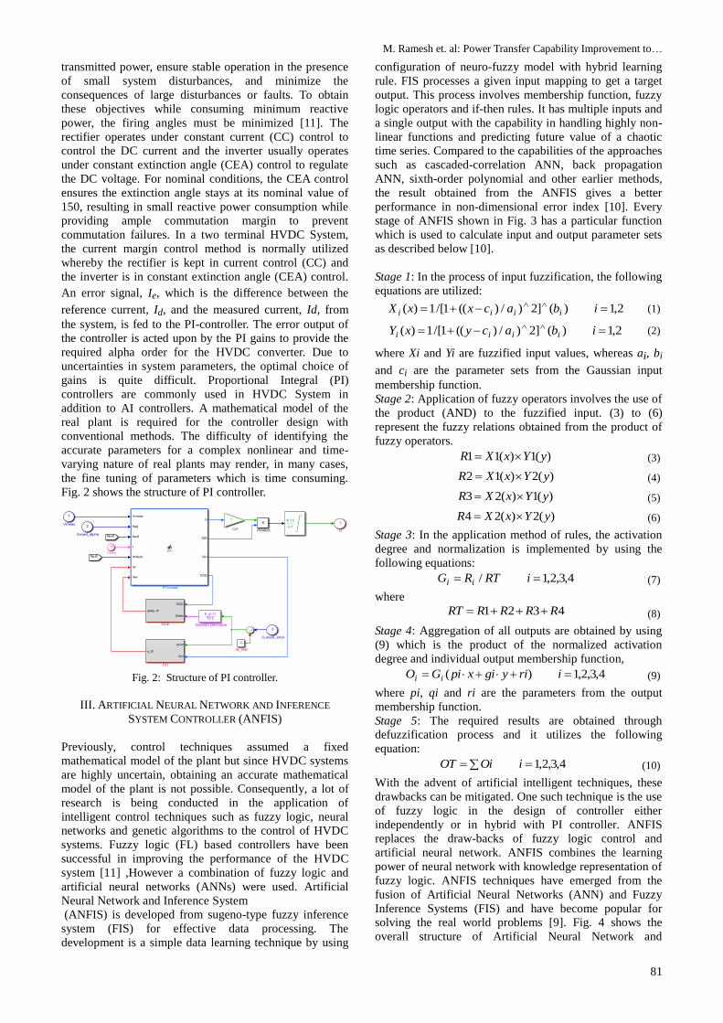
performance in non-dimensional error index [10]. Every
stage of ANFIS shown in Fig. 3 has a particular function
which is used to calculate input and output parameter sets
as described below [10].
Stage 1: In the process of input fuzzification, the following
equations are utilized:
2,1)(]2)/)((1/[1)( ibacxxX iiii (1)
2,1)(]2)/)((1/[1)( ibacyxY iiii
(2)
where Xi and Yi are fuzzified input values, whereas ai, bi
and ci are the parameter sets from the Gaussian input
membership function.
Stage 2: Application of fuzzy operators involves the use of
the product (AND) to the fuzzified input. (3) to (6)
represent the fuzzy relations obtained from the product of
fuzzy operators.
)(1)(11 yYxXR (3)
)(2)(12 yYxXR (4)
)(1)(23 yYxXR (5)
)(2)(24 yYxXR (6)
Stage 3: In the application method of rules, the activation
degree and normalization is implemented by using the
following equations:
4,3,2,1/ iRTRG ii (7)
where
4321 RRRRRT (8)
Stage 4: Aggregation of all outputs are obtained by using
(9) which is the product of the normalized activation
degree and individual output membership function,
4,3,2,1)( iriygixpiGO ii (9)
where pi, qi and ri are the parameters from the output
membership function.
Stage 5: The required results are obtained through
defuzzification process and it utilizes the following
equation:
4,3,2,1 iOiOT (10)
With the advent of artificial intelligent techniques, these
drawbacks can be mitigated. One such technique is the use
of fuzzy logic in the design of controller either
independently or in hybrid with PI controller. ANFIS
replaces the draw-backs of fuzzy logic control and
artificial neural network. ANFIS combines the learning
power of neural network with knowledge representation of
fuzzy logic. ANFIS techniques have emerged from the
fusion of Artificial Neural Networks (ANN) and Fuzzy
Inference Systems (FIS) and have become popular for
solving the real world problems [9]. Fig. 4 shows the
overall structure of Artificial Neural Network and
Asian Power Electronics Journal, Vol. 8, No. 3, Dec 2014
82
Inference System model. Fig. 5 shows HVDC System with
ANFIS Controller.
Fig. 3: Basic ANFIS structure.
Fig. 4: Artificial Neural Network and Inference System
model.
Fig. 5: HVDC system with ANFIS controller.
IV. COMPARISON ON PERFORMANCE ASSESSMENT OF
ANFIS CONTROLLER BASED HVDC TRANSMISSION
SYSTEM
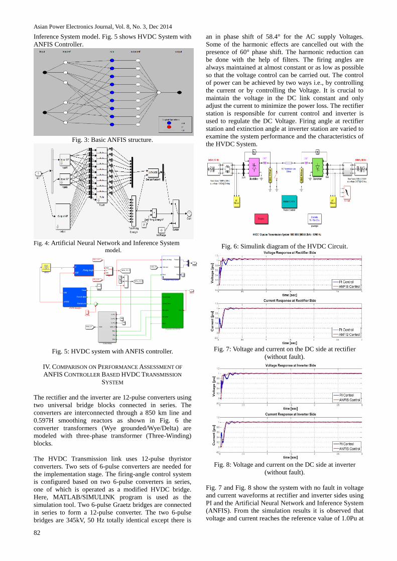
The rectifier and the inverter are 12-pulse converters using
two universal bridge blocks connected in series. The
converters are interconnected through a 850 km line and
0.597H smoothing reactors as shown in Fig. 6 the
converter transformers (Wye grounded/Wye/Delta) are
modeled with three-phase transformer (Three-Winding)
blocks.
The HVDC Transmission link uses 12-pulse thyristor
converters. Two sets of 6-pulse converters are needed for
the implementation stage. The firing-angle control system
is configured based on two 6-pulse converters in series,
one of which is operated as a modified HVDC bridge.
Here, MATLAB/SIMULINK program is used as the
simulation tool. Two 6-pulse Graetz bridges are connected
in series to form a 12-pulse converter. The two 6-pulse
bridges are 345kV, 50 Hz totally identical except there is
an in phase shift of 58.4° for the AC supply Voltages.
Some of the harmonic effects are cancelled out with the
presence of 60° phase shift. The harmonic reduction can
be done with the help of filters. The firing angles are
always maintained at almost constant or as low as possible
so that the voltage control can be carried out. The control
of power can be achieved by two ways i.e., by controlling
the current or by controlling the Voltage. It is crucial to
maintain the voltage in the DC link constant and only
adjust the current to minimize the power loss. The rectifier
station is responsible for current control and inverter is
used to regulate the DC Voltage. Firing angle at rectifier
station and extinction angle at inverter station are varied to
examine the system performance and the characteristics of
the HVDC System.
Fig. 6: Simulink diagram of the HVDC Circuit.
Fig. 7: Voltage and current on the DC side at rectifier
(without fault).
Fig. 8: Voltage and current on the DC side at inverter
(without fault).
Fig. 7 and Fig. 8 show the system with no fault in voltage
and current waveforms at rectifier and inverter sides using
PI and the Artificial Neural Network and Inference System
(ANFIS). From the simulation results it is observed that
voltage and current reaches the reference value of 1.0Pu at
M. Ramesh et. al: Power Transfer Capability Improvement to…
83
0.25 second, i.e. about 0.1 seconds later after starting
HVDC System. It is clear that for no fault, both the
controllers perform well but ANFIS gives a better
transient performance and quite a low overshoot as
compared to the conventional PI controller. The complete
HVDC system reaches stable state after 0.25sec.
Fig. 9: Active power at rectifier.
Fig.9 shows the change process of the active power of
HVDC system without fault with PI controller and the
Artificial Neural Network and Inference System (ANFIS).
It is clear that for no fault, both the controllers perform
well but ANFIS gives a better transient performance and
quite a low overshoot as compared to the conventional PI
controller.
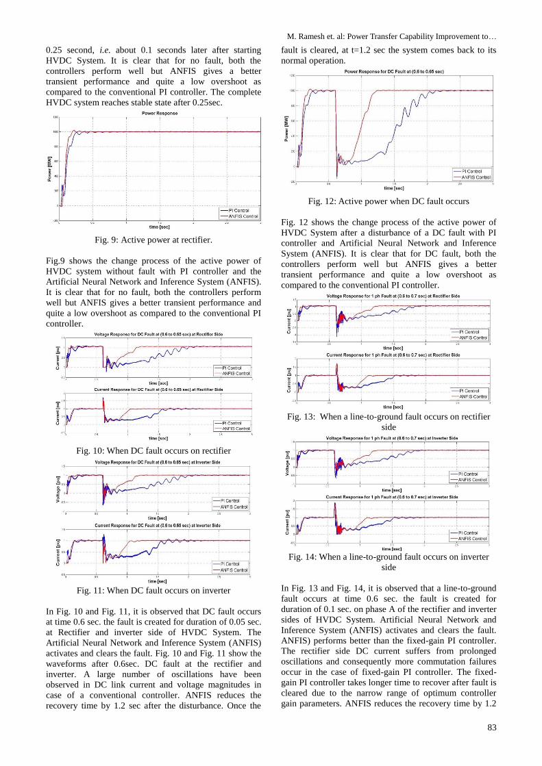
Fig. 10: When DC fault occurs on rectifier
Fig. 11: When DC fault occurs on inverter
In Fig. 10 and Fig. 11, it is observed that DC fault occurs
at time 0.6 sec. the fault is created for duration of 0.05 sec.
at Rectifier and inverter side of HVDC System. The
Artificial Neural Network and Inference System (ANFIS)
activates and clears the fault. Fig. 10 and Fig. 11 show the
waveforms after 0.6sec. DC fault at the rectifier and
inverter. A large number of oscillations have been
observed in DC link current and voltage magnitudes in
case of a conventional controller. ANFIS reduces the
recovery time by 1.2 sec after the disturbance. Once the
fault is cleared, at t=1.2 sec the system comes back to its
normal operation.
Fig. 12: Active power when DC fault occurs
Fig. 12 shows the change process of the active power of
HVDC System after a disturbance of a DC fault with PI
controller and Artificial Neural Network and Inference
System (ANFIS). It is clear that for DC fault, both the
controllers perform well but ANFIS gives a better
transient performance and quite a low overshoot as
compared to the conventional PI controller.
Fig. 13: When a line-to-ground fault occurs on rectifier
side
Fig. 14: When a line-to-ground fault occurs on inverter
side
In Fig. 13 and Fig. 14, it is observed that a line-to-ground
fault occurs at time 0.6 sec. the fault is created for
duration of 0.1 sec. on phase A of the rectifier and inverter
sides of HVDC System. Artificial Neural Network and
Inference System (ANFIS) activates and clears the fault.
ANFIS) performs better than the fixed-gain PI controller.
The rectifier side DC current suffers from prolonged
oscillations and consequently more commutation failures
occur in the case of fixed-gain PI controller. The fixed-
gain PI controller takes longer time to recover after fault is
cleared due to the narrow range of optimum controller
gain parameters. ANFIS reduces the recovery time by 1.2
Asian Power Electronics Journal, Vol. 8, No. 3, Dec 2014
84
sec after the disturbance. Once the fault is cleared, at t=1.2
sec the system comes back to its normal operation.
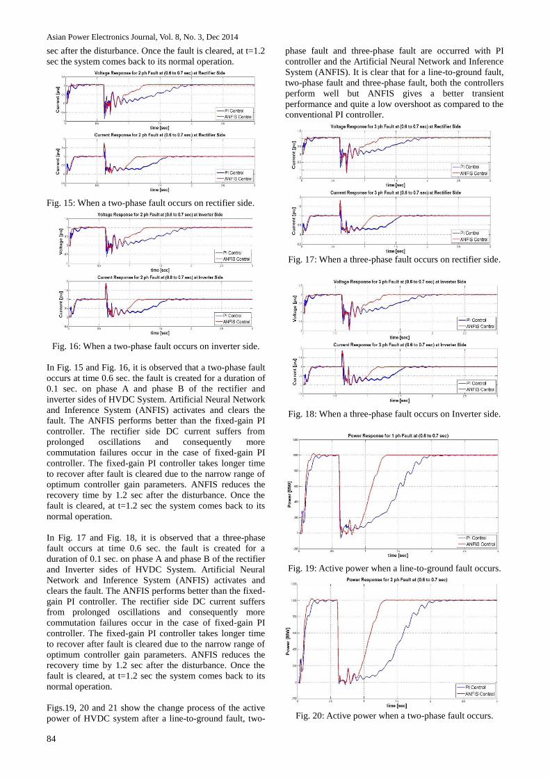
Fig. 15: When a two-phase fault occurs on rectifier side.
Fig. 16: When a two-phase fault occurs on inverter side.
In Fig. 15 and Fig. 16, it is observed that a two-phase fault
occurs at time 0.6 sec. the fault is created for a duration of
0.1 sec. on phase A and phase B of the rectifier and
inverter sides of HVDC System. Artificial Neural Network
and Inference System (ANFIS) activates and clears the
fault. The ANFIS performs better than the fixed-gain PI
controller. The rectifier side DC current suffers from
prolonged oscillations and consequently more
commutation failures occur in the case of fixed-gain PI
controller. The fixed-gain PI controller takes longer time
to recover after fault is cleared due to the narrow range of
optimum controller gain parameters. ANFIS reduces the
recovery time by 1.2 sec after the disturbance. Once the
fault is cleared, at t=1.2 sec the system comes back to its
normal operation.
In Fig. 17 and Fig. 18, it is observed that a three-phase
fault occurs at time 0.6 sec. the fault is created for a
duration of 0.1 sec. on phase A and phase B of the rectifier
and Inverter sides of HVDC System. Artificial Neural
Network and Inference System (ANFIS) activates and
clears the fault. The ANFIS performs better than the fixed-
gain PI controller. The rectifier side DC current suffers
from prolonged oscillations and consequently more
commutation failures occur in the case of fixed-gain PI
controller. The fixed-gain PI controller takes longer time
to recover after fault is cleared due to the narrow range of
optimum controller gain parameters. ANFIS reduces the
recovery time by 1.2 sec after the disturbance. Once the
fault is cleared, at t=1.2 sec the system comes back to its
normal operation.
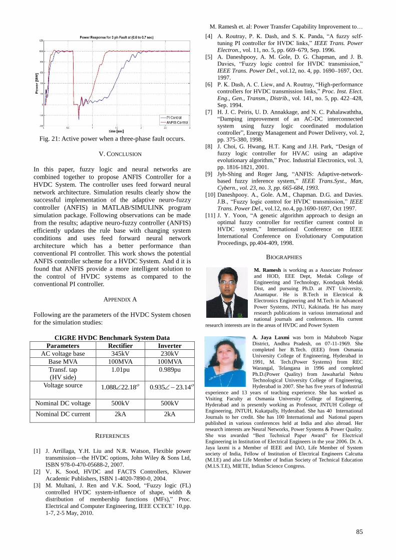
Figs.19, 20 and 21 show the change process of the active
power of HVDC system after a line-to-ground fault, two-
phase fault and three-phase fault are occurred with PI
controller and the Artificial Neural Network and Inference
System (ANFIS). It is clear that for a line-to-ground fault,
two-phase fault and three-phase fault, both the controllers
perform well but ANFIS gives a better transient
performance and quite a low overshoot as compared to the
conventional PI controller.
Fig. 17: When a three-phase fault occurs on rectifier side.
Fig. 18: When a three-phase fault occurs on Inverter side.
Fig. 19: Active power when a line-to-ground fault occurs.
Fig. 20: Active power when a two-phase fault occurs.
M. Ramesh et. al: Power Transfer Capability Improvement to…
85
Fig. 21: Active power when a three-phase fault occurs.
V. CONCLUSION
In this paper, fuzzy logic and neural networks are
combined together to propose ANFIS Controller for a
HVDC System. The controller uses feed forward neural
network architecture. Simulation results clearly show the
successful implementation of the adaptive neuro-fuzzy
controller (ANFIS) in MATLAB/SIMULINK program
simulation package. Following observations can be made
from the results; adaptive neuro-fuzzy controller (ANFIS)
efficiently updates the rule base with changing system
conditions and uses feed forward neural network
architecture which has a better performance than
conventional PI controller. This work shows the potential
ANFIS controller scheme for a HVDC System. And d it is
found that ANFIS provide a more intelligent solution to
the control of HVDC systems as compared to the
conventional PI controller.
APPENDIX A
Following are the parameters of the HVDC System chosen
for the simulation studies:
CIGRE HVDC Benchmark System Data
Parameters Rectifier Inverter
AC voltage base 345kV 230kV
Base MVA 100MVA 100MVA
Transf. tap
(HV side)
1.01pu 0.989pu
Voltage source 18.22088.1 14.23935.0
Nominal DC voltage 500kV 500kV
Nominal DC current 2kA 2kA
REFERENCES
[1] J. Arrillaga, Y.H. Liu and N.R. Watson, Flexible power
transmission—the HVDC options, John Wiley & Sons Ltd,
ISBN 978-0-470-05688-2, 2007.
[2] V. K. Sood, HVDC and FACTS Controllers, Kluwer
Academic Publishers, ISBN 1-4020-7890-0, 2004.
[3] M. Multani, J. Ren and V.K. Sood, “Fuzzy logic (FL)
controlled HVDC system-influence of shape, width &
distribution of membership functions (MFs),” Proc.
Electrical and Computer Engineering, IEEE CCECE’ 10,pp.
1-7, 2-5 May, 2010.
[4] A. Routray, P. K. Dash, and S. K. Panda, “A fuzzy self-
tuning PI controller for HVDC links,” IEEE Trans. Power
Electron., vol. 11, no. 5, pp. 669–679, Sep. 1996.
[5] A. Daneshpooy, A. M. Gole, D. G. Chapman, and J. B.
Davies, “Fuzzy logic control for HVDC transmission,”
IEEE Trans. Power Del., vol.12, no. 4, pp. 1690–1697, Oct.
1997.
[6] P. K. Dash, A. C. Liew, and A. Routray, “High-performance
controllers for HVDC transmission links,” Proc. Inst. Elect.
Eng., Gen., Transm., Distrib., vol. 141, no. 5, pp. 422–428,
Sep. 1994.
[7] H. J. C. Peiris, U. D. Annakkage, and N. C. Pahalawaththa,
“Damping improvement of an AC-DC interconnected
system using fuzzy logic coordinated modulation
controller”, Energy Management and Power Delivery, vol. 2,
pp. 375-380, 1998.
[8] J. Choi, G. Hwang, H.T. Kang and J.H. Park, “Design of
fuzzy logic controller for HVAC using an adaptive
evolutionary algorithm,” Proc. Industrial Electronics, vol. 3,
pp. 1816-1821, 2001.
[9] Jyh-Shing and Roger Jang, “ANFIS: Adaptive-network-
based fuzzy inference system,” IEEE Trans.Syst., Man,
Cybern., vol. 23, no. 3, pp. 665-684, 1993.
[10] Daneshpooy. A., Gole. A.M., Chapman. D.G. and Davies.
J.B., “Fuzzy logic control for HVDC transmission,” IEEE
Trans. Power Del., vol.12, no.4, pp.1690-1697, Oct 1997.
[11] J. Y. Yoon, “A genetic algorithm approach to design an
optimal fuzzy controller for rectifier current control in
HVDC system,” International Conference on IEEE
International Conference on Evolutionary Computation
Proceedings, pp.404-409, 1998.
BIOGRAPHIES
M. Ramesh is working as a Associate Professor and HOD, EEE Dept, Medak College of
Engineering and Technology, Kondapak Medak
Dist, and pursuing Ph.D. at JNT University, Anantapur. He is B.Tech in Electrical &
Electronics Engineering and M.Tech in Advanced
Power Systems, JNTU, Kakinada. He has many research publications in various international and
national journals and conferences. His current
research interests are in the areas of HVDC and Power System
A. Jaya Laxmi was born in Mahaboob Nagar
District, Andhra Pradesh, on 07-11-1969. She completed her B.Tech. (EEE) from Osmania
University College of Engineering, Hyderabad in
1991, M. Tech.(Power Systems) from REC Warangal, Telangana in 1996 and completed
Ph.D.(Power Quality) from Jawaharlal Nehru
Technological University College of Engineering, Hyderabad in 2007. She has five years of Industrial
experience and 13 years of teaching experience. She has worked as
Visiting Faculty at Osmania University College of Engineering, Hyderabad and is presently working as Professor, JNTUH College of
Engineering, JNTUH, Kukatpally, Hyderabad. She has 40 International
Journals to her credit. She has 100 International and National papers
published in various conferences held at India and also abroad. Her
research interests are Neural Networks, Power Systems & Power Quality. She was awarded “Best Technical Paper Award” for Electrical
Engineering in Institution of Electrical Engineers in the year 2006. Dr. A.
Jaya laxmi is a Member of IEEE and IAO, Life Member of System society of India, Fellow of Institution of Electrical Engineers Calcutta
(M.I.E) and also Life Member of Indian Society of Technical Education
(M.I.S.T.E), MIETE, Indian Science Congress.