Embed Size (px)
Citation preview
Power transformer fault diagnosis system based on Internet of ThingsGuoshi Wang1*, Ying Liu2, Xiaowen Chen1, Qing Yan1, Haibin Sui1, Chao Ma1 and Junfei Zhang1
1 IntroductionIn the power supply system, transformer plays an important role in power production and transmission. If the transformer breaks down suddenly in the process of operation, it will cause serious harm to human safety and economic property. Therefore, it is of great value to improve the specific monitoring and troubleshooting of transformers.
The application of the Internet of Things to the power system can not only improve the basic network of power transmission and communication, but also enhance the security and stability of its transmission and communication network. As the main
Abstract: Transformer is the most important equipment in the power system. The research and development of fault diagnosis technology for Internet of Things equip-ment can effectively detect the operation status of equipment and eliminate hidden faults in time, which is conducive to reducing the incidence of accidents and improv-ing people’s life safety index.
Objective: To explore the utility of Internet of Things in power transformer fault diag-nosis system.
Methods: A total of 30 groups of transformer fault samples were selected, and 10 groups were randomly selected for network training, and the rest samples were used for testing. The matter-element extension mathematical model of power transformer fault diagnosis was established, and the correlation function was improved accord-ing to the characteristics of three ratio method. Each group of power transformer was diagnosed for four months continuously, and the monitoring data and diagnosis were recorded and analyzed result. GPRS communication network is used to complete the communication between data acquisition terminal and monitoring terminal. Accord-ing to the parameters of the database, the working state of the equipment is set, and various sensors are controlled by the instrument driver module to complete the diag-nosis of transformer fault system.
Results: The detection success rate of the power transformer fault diagnosis system model established in this paper is as high as 95.6%, the training error is less than 0.0001, and it can correctly identify the fault types of the non training samples. It can be seen that the technical support of the Internet of Things is helpful to the upgrading and maintenance of the power transformer fault diagnosis system.
Keywords: Internet of things, Power transformer, Fault diagnosis, Wireless communication and network
Open Access
© The Author(s) 2021. Open Access This article is licensed under a Creative Commons Attribution 4.0 International License, which permits use, sharing, adaptation, distribution and reproduction in any medium or format, as long as you give appropriate credit to the original author(s) and the source, provide a link to the Creative Commons licence, and indicate if changes were made. The images or other third party material in this article are included in the article’s Creative Commons licence, unless indicated otherwise in a credit line to the mate-rial. If material is not included in the article’s Creative Commons licence and your intended use is not permitted by statutory regulation or exceeds the permitted use, you will need to obtain permission directly from the copyright holder. To view a copy of this licence, visit http://creat iveco mmons .org/licen ses/by/4.0/.
RESEARCH
Wang et al. J Wireless Com Network (2021) 2021:21 https://doi.org/10.1186/s13638-020-01871-6
*Correspondence: [email protected] 1 Hainan Power Grid Co., Ltd, Haikou 460100, Hainan, ChinaFull list of author information is available at the end of the article
Page 2 of 24Wang et al. J Wireless Com Network (2021) 2021:21
communication channel of distribution network, it can provide the functions that the current public and wireless networks lack. In addition, the Internet of Things can with-stand the power emergency in negative weather and improve the disaster resistance abil-ity of the communication system. The Internet of Things will become an important way for the rapid development of information technology in the future.
Di Renzo’s research relied on modeling the location of the base station as the points of spatial Poisson point process, and carries out system level analysis by using ran-dom geometry. The trade-off between wireless information and power transmission is described by the concept of "feasible region," and quantified by the joint cumula-tive distribution function of average power and average rate. Di Renzo proposed a new mathematical method to analyze and optimize cellular low-energy mobile devices with wireless information and power transmission capabilities. The method is ingenious, but requires high accuracy, and needs to be improved in practical application [1]. In order to reduce the difficulty of data acquisition and transmission in the fault diagnosis system of mine hoist, and solve the problems of low efficiency of fault diagnosis and unreason-able reasoning process of mine hoist, a fault diagnosis method of mine hoist equipment based on Internet of Things is proposed. Based on ZigBee short-range wireless com-munication technology, the collaborative acquisition system of key components of mine hoisting equipment is designed in the Internet of Things. Juanli adopted remote wireless general packet radio service (GPRS) transmission mode to realize real-time data acqui-sition and network layer establishment. Juanli through the fault diagnosis test of mine hoist, the diagnosis method obtains complete diagnosis data, and the diagnosis result of this method has high accuracy and reliability [2]. Qian designed a relay with dual inter-face of wireless and PLC, which connects PLC and wireless sensor into an Internet of Things network. In addition, the dual interface relay adaptively selects the interface to forward the message according to the channel state. Qian proposed a general mathe-matical model of the dual interface relay protection system. According to the statistical characteristics of PLC and wireless channel, Qian derived the probability density func-tion of output signal-to-noise ratio (SNR). Qian’s research has constructed the general mathematical model of double interface relay protection system. This method has high accuracy, but lacks feasibility [3]. Zikria connected the digital and physical worlds by combining energy-efficient microcontrollers, low-power transceivers, sensors, and actu-ators in so-called "small objects." In general, intelligent objects are severely limited in computing, memory and energy resources. New verification methods and experimen-tal tools are needed to study the intelligent object network, new software platform is needed to operate intelligent objects effectively, and innovative network models and protocols are needed to interconnect intelligent objects. Zikria’s research connected the digital world with the physical world, which has many innovations, but needs more veri-fication methods to support the accuracy of the research data [4].
In this paper, a total of 30 groups of transformer fault samples are selected, and 10 groups are randomly selected for network training, and the remaining samples are used for testing. The transformer fault diagnosis system model is established for each group of power transformers for four consecutive months, and the monitoring data and diagnosis results are recorded and analyzed. The communication network uses GPRS to realize the communication between the data acquisition terminal and the monitoring terminal.

Page 3 of 24Wang et al. J Wireless Com Network (2021) 2021:21
According to the parameters of the sample library, the working state of the equipment is set, and various sensors are controlled by the instrument driver module to complete the detection of the transformer fault system. The results show that the detection success rate of the power transformer fault diagnosis using this model is as high as 95.6, and the training error is less than 0.0001, and it can accurately identify the fault types of the sam-ples in the non training set.
2 Principle about Internet of Things and fault diagnosis system2.1 Internet of Things
1. Combination of Internet of Things technology and smart grid
Since its successful development, the Internet of Things has undergone many signifi-cant changes. From the logistics network mainly relying on radio frequency identifica-tion technology at the beginning, it has now been studied that a variety of information sensing equipment relying on Internet technology, sensing technology and computer technology can use Internet facilities for information exchange, coordination and pro-cessing. Then, it is an interconnection to meet the requirements of information exchange between people and objects in various regions or large areas [5, 6]. The application of Internet of Things technology in smart grid can realize the perception and exchange of advanced level, convenient operation and unified standard communication information, and complete the distributed intelligent information transmission, measurement and control. Using smart sensors to connect a variety of equipment and facilities as a whole, and then constitute an integrated information service system, not only can process and analyze a variety of information, but also can save costs through this way, and optimize the operation and control of power grid.
2. The role of IOT technology in power maintenance
The periodic maintenance mode formulated in 1950s is used for the maintenance of power equipment in China. So far, the main maintenance mode is still the method [7, 8]. There are two inevitable deficiencies in this method. One is the large-scale maintenance of normal equipment, the other is the equipment damage caused by accidents, which forces the regular maintenance to inevitably lead to a large amount of human and mate-rial resources consumption.
The primary problem to be solved by Internet of Things technology is information acquisition. How to process information and how to realize overhaul decision should be scientifically planned [9, 10]. As an independent management subject, maintenance management is inseparable from the advanced technology management system. A vari-ety of maintenance systems are composed of various management objectives in many countries around the world. Under the condition of market factors and technical level, a maintenance management mechanism including conditional maintenance and flexible application of various methods is proposed. The addition of diagnosis expert system can make the reliability and safety of the system meet the level of people’s needs, and opti-mize the maintenance plan and maintenance process.

Page 4 of 24Wang et al. J Wireless Com Network (2021) 2021:21
3 Power transformer
1. Brief introduction
Power transformer is one of the key equipment of power system, and its reliable operation characteristic is the guarantee of the whole power mechanism to supply power safely. The fault of power transformer will directly interfere with the normal operation of the power system, and also cause serious harm to the economy of power companies and power users [11]. At present, the power system is developing rapidly in the direction of ultra-high voltage, large power grid and automation, and the influ-ence and interference of transformer fault on the normal operation of power system is becoming more and more serious [12]. Because the improvement process of power transformer fault is related to the operating environment, load capacity and insula-tion level, it is difficult to find out some hidden faults immediately by using preventive maintenance means. Preventive maintenance not only needs high cost, but also does not have advanced level for development faults such as insulation. Therefore, it is very useful to detect the transformer running fault system on-line at any time. The combi-nation of on-line detection technology and intelligent diagnosis of transformer fault can timely discover the hidden dangers in the development, reduce the probability of accidents, and do a good job of prevention.
2. Application of power transformer
In the contemporary society, electricity is a particularly important energy, it has pen-etrated into every corner of human society. However, the power generated by power plants usually needs to be transported over long distances to reach the power area [13, 14]. When the transmission power is fixed, because the voltage and current are in positive proportion, the current required for transmission decreases with the increase in voltage. Because the impedance of the transmission path is almost a fixed value, and the line loss is proportional to the square of the current, increasing the transmis-sion voltage can greatly reduce the line voltage drop and line loss. At present, there are great difficulties in the manufacture of high-voltage generators. Therefore, spe-cial equipment must be used to boost the voltage before the voltage at the end of the generator is sent out. This special equipment is the transformer. In addition, at the receiving end, it is necessary to use step-down transformer to reduce the high-voltage to the distribution system voltage, so many distribution transformers are used to reg-ulate the high-voltage to the exact application value. In the power system, transform-ers occupy a very important position, not only need a large number, but also have high efficiency and stable operation.
When the transformer is in operation, the transformer will fail due to various fac-tors [15, 16]. If the transformer fails, it will affect the output of the generator, reduce and interrupt the power supply of some users, and prolong the maintenance time of the transformer. If the accident cannot be detected and solved immediately, it will cause serious harm to the conventional power supply and residents’ property.

Page 5 of 24Wang et al. J Wireless Com Network (2021) 2021:21
3.1 Power transformer fault diagnosis system based on Internet of Things
The decision-level fusion in the system uses extension theory to establish a fault diag-nosis model, uses correlation functions for evaluation, and comprehensively diagno-ses the fault type of the transformer [17, 18]. The specific implementation process of decision-level data fusion based on extension theory is as follows:
1. Structure matter element matrix
According to the concept of matter element and the ratio coding of each transformer and the fault type, the transformer fault type is divided into 9 levels, namely: U = {u1, u2, u4, u5, u6, u7, u8, u9} = {I1, I2, I4, I5, I6, I7, I8, I9}, and according to the three ratio codes of C2H2/C2H4, CH4/H2, C2H4/C2H6 and the corresponding failure interval, the three-dimensional matter element matrix constructed is:
The classic domain-free matrix for determining the fault type is:
The analysis result of the detected dissolved gas in the transformer oil is repre-sented by the matter element Z0, and the following three-dimensional matrix of the matter to be diagnosed is obtained:
2. Determine the substance to be diagnosed
3. For the status information of each group of data, the steps to determine the objective weight of the status information between components by the Ou method are as fol-lows:
(1)Z =
Transformer Ratio of C2H2/C2H4 Quantities of Failure Types V1
Fault Type Ratio of CH4/H2 Quantities of Failure Types V2
U Ratio of C2H4/C2H6 Quantities of Failure Types V3
(2)BMI (b) = 2n ln(σ )+ n ln(2π)+ n
{
n+ tr(S)
n− 2− tr(S)
}
(3)Zi =
U1 U2 U3 U4 U5 U6 U7 U8 U9
c1 [0, 0.1] [0, 0.1] [0, 0.1] [0, 0.1] [0, 0.1] [0, 1.3] [0.1, 3] [3,∞] [3,∞]
c2 [0.1, 1] [1,∞] [1,∞] [0,∞] [0, 0.1] [0, 1] [3,∞] [0, 1] [1,∞]
c3 [1, 3] [0, 1] [1, 3] [3,∞] [0, 1] [0,∞] [0,∞] [0,∞] [0,∞]
(4)W (T ) = K(
y(T − 1), . . . , y(t − n),u(T − d − 1), . . . ,u(k − d − n))
(5)Z0 =
U0 c1 V1
c2 V 2
c3 V3
Page 6 of 24Wang et al. J Wireless Com Network (2021) 2021:21
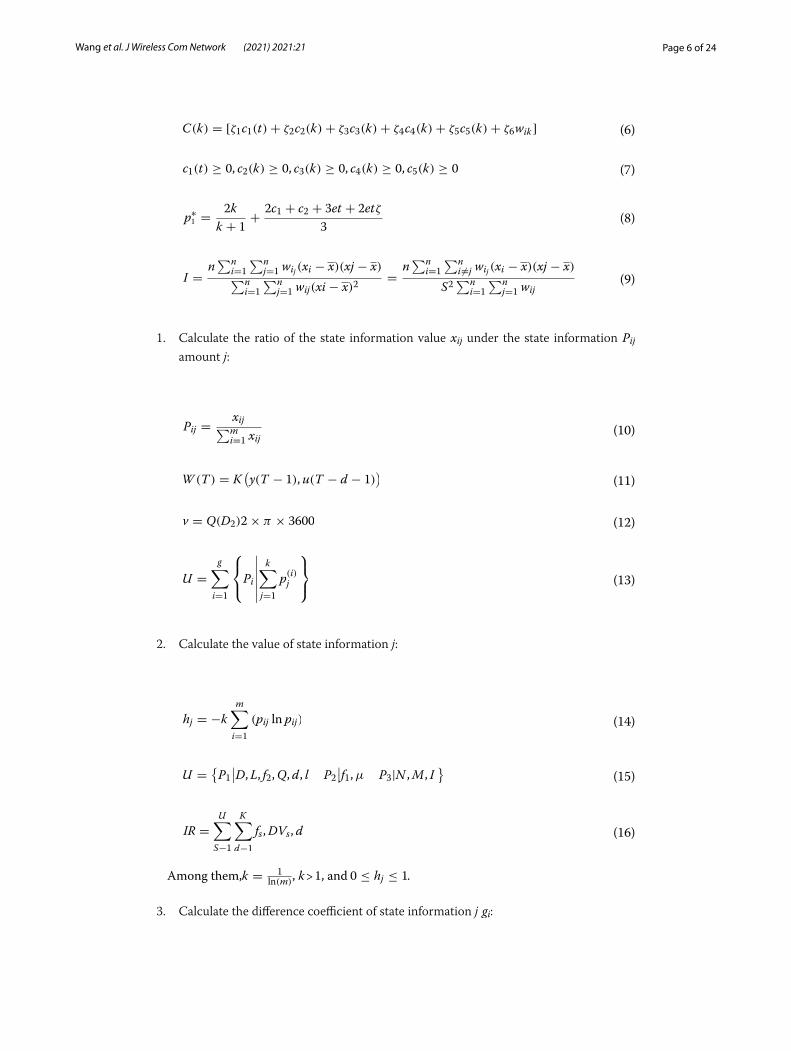
1. Calculate the ratio of the state information value xij under the state information Pij amount j:
2. Calculate the value of state information j:
Among them,k = 1ln(m)
, k > 1, and 0 ≤ hj ≤ 1.
3. Calculate the difference coefficient of state information j gi:
(6)C(k) = [ζ1c1(t)+ ζ2c2(k)+ ζ3c3(k)+ ζ4c4(k)+ ζ5c5(k)+ ζ6wik ]
(7)c1(t) ≥ 0, c2(k) ≥ 0, c3(k) ≥ 0, c4(k) ≥ 0, c5(k) ≥ 0
(8)p∗1 =2k
k + 1+
2c1 + c2 + 3et + 2etζ
3
(9)I =n∑n
i=1
∑nj=1 wij (xi − x)(xj − x)
∑ni=1
∑nj=1 wij(xi − x)2
=n∑n
i=1
∑ni �=j wij (xi − x)(xj − x)
S2∑n
i=1
∑nj=1 wij
(10)Pij =xij
∑mi=1 xij
(11)W (T ) = K(
y(T − 1),u(T − d − 1))
(12)v = Q(D2)2× π × 3600
(13)U =
g�
i=1
Pi
�
�
�
�
�
�
k�
j=1
p(i)j
(14)hj = −k
m∑
i=1
(pij ln pij)
(15)U ={
P1∣
∣D, L, f2,Q, d, l P2∣
∣f1,µ P3|N ,M, I}
(16)IR =
U∑
S−1
K∑
d−1
fs,DVs, d
Page 7 of 24Wang et al. J Wireless Com Network (2021) 2021:21
4. Data collection terminal
1. GPRS communication module
The online monitoring and diagnosis system will use the GR47 module in the embedded TCP/IP protocol stack. The GR47 module mainly includes GPRS communication mod-ule and IP module, which are used to complete the TCP/IP protocol replacement, com-plete the receiving and sending of various information in turn, and provide data supply for GPRS [19, 20]. In order to achieve various types of operating states, this module has also designed various types of interfaces to meet work requirements. The adoption of this module provides a lot of convenience for many users. It is mainly reflected in the fact that the protocol replacement process between TCP and IP does not need to send people to manually operate, which reduces a variety of complicated control time, and makes data transmission more clear and active. The transmitted data can reach the ter-minal of the other party’s network system directly after GR47 processing, which greatly reduces the development time of the system.
2. Fault diagnosis module
After receiving the exact data information, the fault diagnosis module is fused and ana-lyzed, and compared with the sample parameters in the diagnosis database to determine whether the transformer is intact and its failure mechanism [21, 22]. If the fault is a gen-eral type of low function, the diagnostic system will give a warning, allowing the user to complete the simple equipment adjustment according to the given operation steps [23]. When the fault is more serious and the performance is worse, the diagnostic system will compare the collected data with the corresponding parameters of the transformer, ana-lyze the self-check data and important information in the technical reference library in all aspects, and determine the modules that can be replaced after the fault occurs. After meeting the previous requirements, the system will give the user the specified repair steps. In this stage, the system technical guidance from the determination of the trans-former fault type to the fault resolution method is completed.
3. Transformer fault diagnosis based on information fusion technology
Due to the complexity of the transformer manufacturing process and the instability of the operating state, the variety of transformer fault causes is caused, which is mainly reflected in the same type of fault mode with different fault characteristics, and the same type of fault characteristic is the combined result of multiple failure modes [24, 25]. Therefore, there are various nonlinear correspondences between failure modes and failure characteristics. Therefore, in the transformer fault diagnosis, determining its
(17)gi = 1− hj(0 ≤ hj ≤ 1)
(18)βj = (XTWjX)−1XTWjY

Page 8 of 24Wang et al. J Wireless Com Network (2021) 2021:21
relationship is extremely critical. Information fusion technology is to analyze and pro-cess information and data from various information sources, to maximize the use of all fault characteristics of the transformer, to obtain multiple aspects of the same object of the transformer from multiple angles, and to integrate them to achieve better accurate and more scientific online diagnosis. After the initial data evaluation and simple fault diagnosis and analysis, the final result needs to be displayed concisely and clearly on the LCD screen of the monitoring site to facilitate the direct collection of information and management planning.
4 Experiment and analysis4.1 Materials and experimental design
1. Data collection and determination of training samples
Select 30 groups of transformer fault samples, and randomly select 10 groups for net-work training. The remaining samples are used for testing. According to the designed transformer diagnosis system model, each group of power transformers will be diag-nosed for four consecutive months, and the monitoring data will be recorded and analyzed.
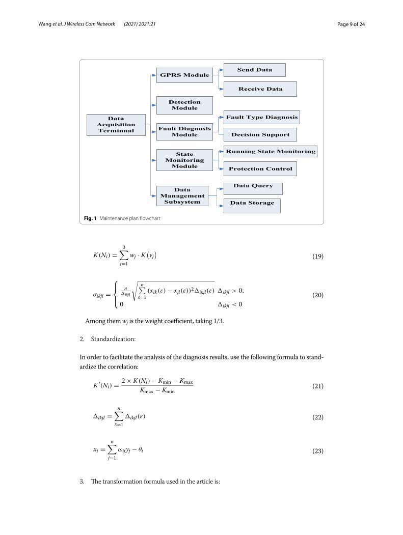
2. Information analysis and processing (flowchart) The GPRS communication network mode is used to complete the communication
between the data acquisition terminal and the monitoring terminal. The data acquisi-tion terminal transmits the data of the detected transformer parameters to the moni-toring terminal or receives the monitoring information of the monitoring terminal. The flowchart of the inspection plan is shown in Fig. 1.
3. Detection and fault diagnosis module Measure the dissolved gas in the transformer oil and cooperate with the monitoring
management system, compare with the standard parameters in the diagnostic knowl-edge base, determine the performance status and fault type of the voltage trans-former, give the user the operation steps for maintenance, and finally complete the fault type analysis of the transformer, and provide data support to technicians.
4. Status monitoring module and IoT management system
Set the operating status of the equipment according to the database parameters, and use the instrument driver module to control multiple sensors to complete the monitor-ing of the transformer operating status, and take appropriate measures to protect and control the transformer.
5. Calculation formulas needed by each module in the experiment
1. Calculate the correlation between the object to be measured and the standard faulty object:
Page 9 of 24Wang et al. J Wireless Com Network (2021) 2021:21
Among them wj is the weight coefficient, taking 1/3.
2. Standardization:
In order to facilitate the analysis of the diagnosis results, use the following formula to stand-ardize the correlation:
3. The transformation formula used in the article is:
(19)K (Ni) =
3∑
j=1
wj · K(
vj)
(20)σikjl =
n�ikjl
�
n�
s=1
(xik(ε)− xjl(ε))2�ikjl(ε) �ikjl > 0;
0 �ikjl < 0
(21)K ′(Ni) =2× K (Ni)− Kmin − Kmax
Kmax − Kmin
(22)�ikjl =
n∑
δ=1
�ikjl(ε)
(23)xi =
n∑
j=1
ωijyj − θi
DataAcquisitionTerminnal
DetectionModule
Fault Diagnosis Module
StateMonitoring
Module
GPRS Module
DataManagement
Subsystem
Send Data
Receive Data
Fault Type Diagnosis
Decision Support
Running State Monitoring
Protection Control
Data Query
Data Storage
Fig. 1 Maintenance plan flowchart
Page 10 of 24Wang et al. J Wireless Com Network (2021) 2021:21
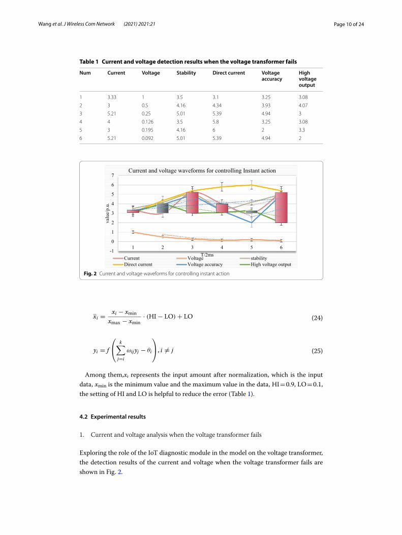
Among them,xi represents the input amount after normalization, which is the input data, xmin is the minimum value and the maximum value in the data, HI = 0.9, LO = 0.1, the setting of HI and LO is helpful to reduce the error (Table 1).
4.2 Experimental results
1. Current and voltage analysis when the voltage transformer fails
Exploring the role of the IoT diagnostic module in the model on the voltage transformer, the detection results of the current and voltage when the voltage transformer fails are shown in Fig. 2.
(24)xi =xi − xmin
xmax − xmin· (HI− LO)+ LO
(25)yi = f
k�
j=i
ωijyj − θi
, i �= j
Table 1 Current and voltage detection results when the voltage transformer fails
Num Current Voltage Stability Direct current Voltage accuracy
High voltage output
1 3.33 1 3.5 3.1 3.25 3.08
2 3 0.5 4.16 4.34 3.93 4.07
3 5.21 0.25 5.01 5.39 4.94 3
4 4 0.126 3.5 5.8 3.25 3.08
5 3 0.195 4.16 6 2 3.3
6 5.21 0.092 5.01 5.39 4.94 2
-1
0
1
2
3
4
5
6
7
1 2 3 4 5 6
valu
e/p.
u.
T/2ms
Current and voltage waveforms for controlling Instant action
Current Voltage stabilityDirect current Voltage accuracy High voltage output
Fig. 2 Current and voltage waveforms for controlling instant action

Page 11 of 24Wang et al. J Wireless Com Network (2021) 2021:21
It can be seen from Fig. 2 that the average voltage of the transformer sample is not higher than 3 V every 2 ms, and the fault location also has an impact on the cur-rent and voltage after the fault, but the DC line resistance is relatively small, so the fault location has little effect on the short-circuit current and voltage. Therefore, the diagnosis method using the Internet of Things technology comprehensively uses the entropy method to assign weights to each single diagnosis module, which reduces the error interference, and the diagnosis accuracy is much higher than that of the single diagnosis method, which can reflect the amount of uncertainty information of ran-dom variables. Use the acquired data information to eliminate the influence of sub-jective factors and reflect the state of the system more objectively. The system state information is shown in Table 2.
As shown in Fig. 3, because the transformer input and output power supply is 5 V, its core and on-chip peripherals power supply is 3.3 V, so the system uses two sets of regulated power supplies. The 220 V AC power is first stepped down by a step-down transformer, the step-down AC power is rectified to DC by the rectifier bridge, fil-tered by C1, and then entered into the LM7805 voltage regulator module, and finally output 5 V DC after R1 is divided. As shown in Table 3, the IoT system diagnoses that if the 5 V DC power is used in the sample and the high voltage output is 5.5 V, the device has characteristics such as low output current, low output voltage accuracy, and lack of stability.
Table 2 Make full use of the acquired data and information results
Rectifier C1 LM7805 R1-pressure D-current I-Things Regulator
Input 1.96 2.17 2.45 2.08 2.08 2.35 2.45
Output 2.77 2.48 2.75 2.89 2.88 2.34 2.83
Kernel 3.33 1.3 3.5 3.1 3.25 3.08 3.06
Regulated 4.42 4.28 4.16 4.34 3.93 4.07 4.47
Alternating 5.21 5.36 5.01 5.39 4.94 5.38 4.8
Step-down 4.84 5.34 5.45 5.45 4.94 5.24 2.3
05
10152025303540
Input Output Kernel Regulated Alternating Step-down
Tran
sfor
mer
stab
ility
inde
x
Transformer interface type
The relarelationship between step-down module and step-down stabilityregulator I-Things D-current R1-pressure LM7805 C1 Rectifier
Fig. 3 The relationship between step-down module and step-down stability

Page 12 of 24Wang et al. J Wireless Com Network (2021) 2021:21
As shown in Fig. 4, the joint GPRS communication module and IP module are used to complete the TCP/IP protocol replacement, which in turn completes the receiving and sending of various information, and provides data supply for GPRS; 100 sensing nodes are randomly deployed in an area of 100 × 100, and the communication distance of all sensing nodes is set to 50 m, and the fault diagnosis situation when the node failure rate of the wireless sensor network of the sensing layer of the Internet of Things is 0.05 ~ 0.30 is reduced. This kind of complicated control time, the operation time corresponding to various node failures is shown in Table 4.
As shown in Fig. 5, the decision-level fusion in the research system of this paper uses extension theory to establish a fault diagnosis model, constructs a matter-element matrix and uses correlation functions for evaluation, which can comprehensively diagnose the fault types of power transformers, thereby making data transmission more clear, and the actively transmitted data can directly reach the terminal of the other party’s network sys-tem after GR47 processing, which greatly reduces the development time of the system.
Table 3 The IoT system diagnoses the sample
Num R-deployment N-communication IoT perception Node failure Troubleshooting
1 2.08 2.1 2.37 1.86 0.3
2 2.17 2.34 2.25 0.6 2.01
3 2.08 5 2.18 1.97 1.83
4 2.29 1.84 0.3 2.02 2.22
5 2.3 2.6 2.41 4.3 2.82
6 3.07 3.06 3.46 3.23 1.6
0% 10% 20% 30% 40% 50% 60% 70% 80% 90% 100%
1
2
3
4
5
6
Failure rate
Mod
ule
com
pone
nts
Comparison of communication module processing information failure rateR-deployment N-communication IoT perception Node failure Troubleshooting
Fig. 4 Comparison of communication module processing information failure rate
Table 4 Reduced a variety of complicated control time
Decision Fault-DM Matter Correlation Diagnosis Power transformer
3.28 3.86 2.32 4.86 3.02 2.47
3.08 3.8 5.49 4.93 1.12 1.96
3.34 4.26 5.36 4.96 7.44 2.24
2.91 3.88 1.02 5.33 7.15 2.04
3.25 1.32 5.3 5.25 7.07 2.12
Page 13 of 24Wang et al. J Wireless Com Network (2021) 2021:21
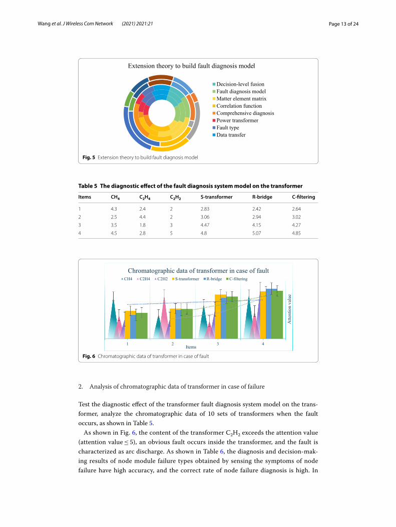
2. Analysis of chromatographic data of transformer in case of failure
Test the diagnostic effect of the transformer fault diagnosis system model on the trans-former, analyze the chromatographic data of 10 sets of transformers when the fault occurs, as shown in Table 5.
As shown in Fig. 6, the content of the transformer C2H2 exceeds the attention value (attention value ≤ 5), an obvious fault occurs inside the transformer, and the fault is characterized as arc discharge. As shown in Table 6, the diagnosis and decision-mak-ing results of node module failure types obtained by sensing the symptoms of node failure have high accuracy, and the correct rate of node failure diagnosis is high. In
Extension theory to build fault diagnosis model
Decision-level fusionFault diagnosis modelMatter element matrixCorrelation functionComprehensive diagnosisPower transformerFault typeData transfer
Fig. 5 Extension theory to build fault diagnosis model
Table 5 The diagnostic effect of the fault diagnosis system model on the transformer
Items CH4 C2H4 C2H2 S-transformer R-bridge C-filtering
1 4.3 2.4 2 2.83 2.42 2.64
2 2.5 4.4 2 3.06 2.94 3.02
3 3.5 1.8 3 4.47 4.15 4.27
4 4.5 2.8 5 4.8 5.07 4.85
Fig. 6 Chromatographic data of transformer in case of fault
Page 14 of 24Wang et al. J Wireless Com Network (2021) 2021:21
this system, the Internet of Things network has strong self-learning ability, robust-ness and anti-interference ability, and can determine the redundant test sample data. Therefore, the model constructed in this paper has more excellent characteristics when applied to transformer fault diagnosis.
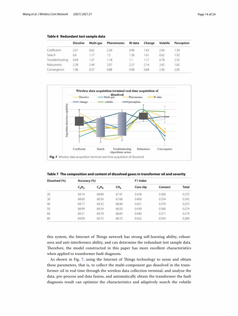
As shown in Fig. 7, using the Internet of Things technology to sense and obtain these parameters, that is, to collect the multi-component gas dissolved in the trans-former oil in real time through the wireless data collection terminal, and analyze the data, pre-process and data fusion, and automatically obtain the transformer the fault diagnosis result can optimize the characteristics and adaptively search the volatile
Table 6 Redundant test sample data
Dissolve Multi-gas Pheromones W-data Change Volatile Perception
Coefficient 2.01 0.62 2.26 0.96 1.63 2.06 1.39
Search 0.6 1.17 1.5 1.36 1.61 0.62 1.92
Troubleshooting 0.69 1.37 1.18 1.1 1.17 0.78 2.32
Robustness 2.28 2.49 2.07 2.27 2.14 2.42 1.82
Convergence 1.96 0.37 0.88 0.96 0.68 2.36 2.05
Coefficient Search Troubleshooting Robustness Convergence
Alg
orith
m d
etec
tion
capa
bilit
y
Algorithmic action
Wireless data acquisition terminal real-time acquisition of dissolved
Dissolve Multi-gas Pheromones W-data
change volatile perception
Fig. 7 Wireless data acquisition terminal real-time acquisition of dissolved
Table 7 The composition and content of dissolved gases in transformer oil and severity
Dissolved (%) Accuracy (%) F1 Index
C2H2 C2H4 CH4 Core clip Connect Total
20 69.14 68.89 67.91 0.428 0.360 0.225
30 68.60 68.56 67.66 0.409 0.354 0.242
40 69.17 69.32 68.40 0.421 0.379 0.255
50 68.99 69.54 68.50 0.439 0.360 0.274
60 69.21 69.79 68.83 0.440 0.371 0.279
80 69.09 69.72 68.72 0.422 0.354 0.289
Page 15 of 24Wang et al. J Wireless Com Network (2021) 2021:21
coefficient to change the pheromone, so that the algorithm detection ability reaches 87%, enhance the robustness of the network and accelerate the convergence.
As shown in Table 7, the composition and content of dissolved gas in transformer oil are closely related to the type of fault and the severity of the fault. The Internet of Things model combines qualitative and quantitative aspects to study the laws and methods for solving contradictory problems, and establish things the matter-element evaluation model of multiple index parameters can completely reflect the comprehen-sive quality level of things.
3. Research on the effect of model processing after diagnosis
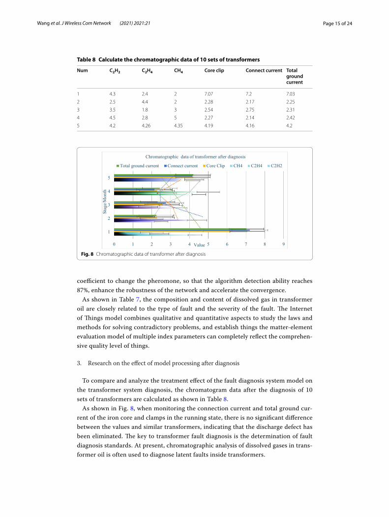
To compare and analyze the treatment effect of the fault diagnosis system model on the transformer system diagnosis, the chromatogram data after the diagnosis of 10 sets of transformers are calculated as shown in Table 8.
As shown in Fig. 8, when monitoring the connection current and total ground cur-rent of the iron core and clamps in the running state, there is no significant difference between the values and similar transformers, indicating that the discharge defect has been eliminated. The key to transformer fault diagnosis is the determination of fault diagnosis standards. At present, chromatographic analysis of dissolved gases in trans-former oil is often used to diagnose latent faults inside transformers.
Table 8 Calculate the chromatographic data of 10 sets of transformers
Num C2H2 C2H4 CH4 Core clip Connect current Total ground current
1 4.3 2.4 2 7.07 7.2 7.03
2 2.5 4.4 2 2.28 2.17 2.25
3 3.5 1.8 3 2.54 2.75 2.31
4 4.5 2.8 5 2.27 2.14 2.42
5 4.2 4.26 4.35 4.19 4.16 4.2
Fig. 8 Chromatographic data of transformer after diagnosis
Page 16 of 24Wang et al. J Wireless Com Network (2021) 2021:21
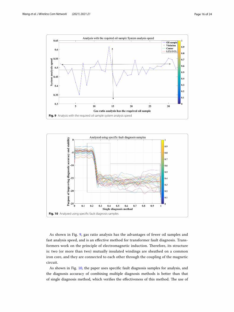
As shown in Fig. 9, gas ratio analysis has the advantages of fewer oil samples and fast analysis speed, and is an effective method for transformer fault diagnosis. Trans-formers work on the principle of electromagnetic induction. Therefore, its structure is: two (or more than two) mutually insulated windings are sheathed on a common iron core, and they are connected to each other through the coupling of the magnetic circuit.
As shown in Fig. 10, the paper uses specific fault diagnosis samples for analysis, and the diagnosis accuracy of combining multiple diagnosis methods is better than that of single diagnosis method, which verifies the effectiveness of this method. The use of
Fig. 9 Analysis with the required oil sample system analysis speed
Fig. 10 Analyzed using specific fault diagnosis samples
Page 17 of 24Wang et al. J Wireless Com Network (2021) 2021:21
Internet of Things diagnostic technology is a new research direction, which can effec-tively combine different diagnostic methods and ideas, make full use of known informa-tion, and achieve the purpose of improving the accuracy and stability of diagnosis.
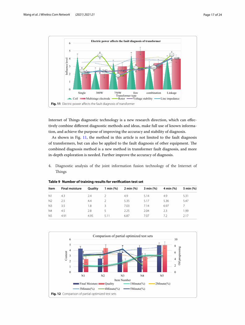
As shown in Fig. 11, the method in this article is not limited to the fault diagnosis of transformers, but can also be applied to the fault diagnosis of other equipment. The combined diagnosis method is a new method in transformer fault diagnosis, and more in-depth exploration is needed. Further improve the accuracy of diagnosis.
4. Diagnostic analysis of the joint information fusion technology of the Internet of Things
0
1
2
3
4
5
6
Single 300W 750W 1kw combination Linkage
Influ
ence
leve
l
Transformer type
Electric power affects the fault diagnosis of transformer
Coil Multistage electrode Rotor Voltage stability Line impedance
Fig. 11 Electric power affects the fault diagnosis of transformer
Table 9 Number of training results for verification test set
Item Final moisture Quality 1 min (%) 2 min (%) 3 min (%) 4 min (%) 5 min (%)
N1 4.3 2.4 2 4.9 5.14 4.9 5.31
N2 2.5 4.4 2 5.35 5.17 5.36 5.47
N3 3.5 1.8 3 7.03 7.14 6.97 7
N4 4.5 2.8 5 2.25 2.04 2.3 1.99
N5 4.91 4.95 5.11 6.87 7.07 7.2 2.17
0
2
4
6
8
10
0
1
2
3
4
5
6
N1 N2 N3 N4 N5
Oil
prog
ress
ing
Con
tent
Item Number
Comparison of partial optimized test sets
Final Moisture Quality 1Minute(%) 2Minute(%)
3Minute(%) 4Minute(%) 5Minute(%)
Fig. 12 Comparison of partial optimized test sets
Page 18 of 24Wang et al. J Wireless Com Network (2021) 2021:21
After training with the training set data, the forward propagation network within the error range is obtained, and then input the test set to verify the training results. The test set data is shown in Table 9.
As shown in Fig. 12, based on the addition of information fusion technology to the Internet of Things, the fault diagnosis system constructed in this article can quickly obtain sample data within 5 Min, which can better cooperate with the terminal data collection link and improve actual efficiency.
As shown in Table 10, the experiment in this article takes the online diagnosis of transformer faults as an example. If a traditional IoT measurement system is used, it will take more than 20 min to get the final fault parameters. In this way, the required measurement time will be very long. It is long and very wasteful of time and cost. Therefore, the combination of extension theory proposed in this paper is used to train the data samples in the Internet of Things to obtain a network model that meets the convergence conditions and apply it to the data processing server. Through the infor-mation fusion technology, the information and data from various information sources are analyzed and processed, and all the fault characteristic quantities of the trans-former are used to the greatest extent, and the multi-faceted information of the same object of the transformer is obtained from multiple angles, and the integrated use can achieve more accurate and more scientific online diagnosis. After the initial data eval-uation and simple fault diagnosis and analysis, the final result needs to be displayed concisely and clearly on the LCD screen of the monitoring site to facilitate the direct collection of information and management planning. The Internet of Things can rea-sonably solve the terminal and communication problems in the distribution network. Only by connecting the equipment and accessories in the distribution network to the Internet, the communication work of the distribution network can be completed, and the remote signaling, remote measurement, and automation technology such as remote control. It can be seen that the Internet of Things can deal with the problem of many and frequently changing power distribution terminals.
5. Training sample statistics
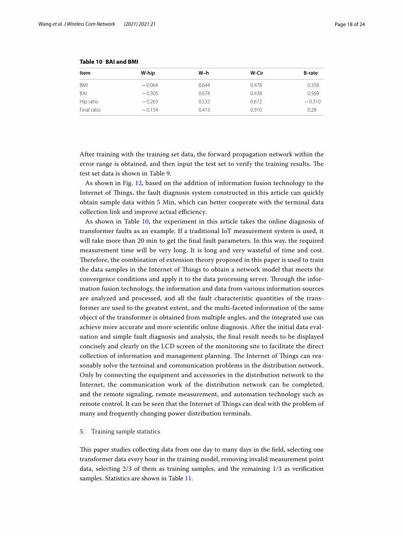
This paper studies collecting data from one day to many days in the field, selecting one transformer data every hour in the training model, removing invalid measurement point data, selecting 2/3 of them as training samples, and the remaining 1/3 as verification samples. Statistics are shown in Table 11.
Table 10 BAI and BMI
Item W-hip W–h W-Cir B-rate
BMI − 0.064 0.644 0.478 0.358
BAI − 0.305 0.674 0.438 0.569
Hip ratio − 0.263 0.532 0.672 − 0.310
Final ratio − 0.154 0.413 0.910 0.28
Page 19 of 24Wang et al. J Wireless Com Network (2021) 2021:21
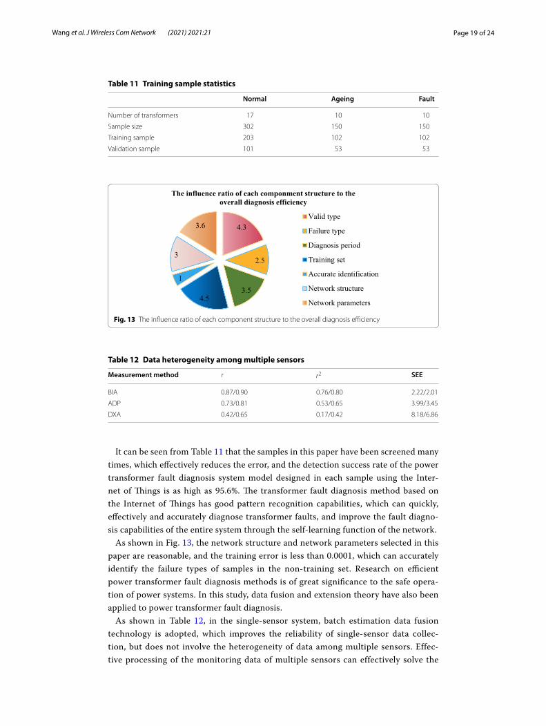
It can be seen from Table 11 that the samples in this paper have been screened many times, which effectively reduces the error, and the detection success rate of the power transformer fault diagnosis system model designed in each sample using the Inter-net of Things is as high as 95.6%. The transformer fault diagnosis method based on the Internet of Things has good pattern recognition capabilities, which can quickly, effectively and accurately diagnose transformer faults, and improve the fault diagno-sis capabilities of the entire system through the self-learning function of the network.
As shown in Fig. 13, the network structure and network parameters selected in this paper are reasonable, and the training error is less than 0.0001, which can accurately identify the failure types of samples in the non-training set. Research on efficient power transformer fault diagnosis methods is of great significance to the safe opera-tion of power systems. In this study, data fusion and extension theory have also been applied to power transformer fault diagnosis.
As shown in Table 12, in the single-sensor system, batch estimation data fusion technology is adopted, which improves the reliability of single-sensor data collec-tion, but does not involve the heterogeneity of data among multiple sensors. Effec-tive processing of the monitoring data of multiple sensors can effectively solve the
Table 11 Training sample statistics
Normal Ageing Fault
Number of transformers 17 10 10
Sample size 302 150 150
Training sample 203 102 102
Validation sample 101 53 53
4.3
2.5
3.54.5
1
3
3.6
The influence ratio of each componment structure to the overall diagnosis efficiency
Valid type
Failure type
Diagnosis period
Training set
Accurate identification
Network structure
Network parameters
Fig. 13 The influence ratio of each component structure to the overall diagnosis efficiency
Table 12 Data heterogeneity among multiple sensors
Measurement method r r2 SEE
BIA 0.87/0.90 0.76/0.80 2.22/2.01
ADP 0.73/0.81 0.53/0.65 3.99/3.45
DXA 0.42/0.65 0.17/0.42 8.18/6.86
Page 20 of 24Wang et al. J Wireless Com Network (2021) 2021:21
problem that a single sensor cannot diagnose the safe state of the transformer, and the problem that the coding rules are incomplete or there are multiple state types.
6. Exploration of diagnosis results
Quoting the transformer fault diagnosis system model and inputting the fault parameters, the diagnosis results obtained are shown in Table 13.
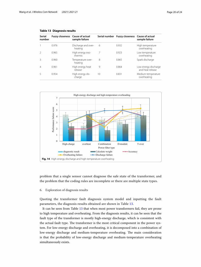
It can be seen from Table 13 that when most power transformers fail, they are prone to high temperature and overheating. From the diagnosis results, it can be seen that the fault type of the transformer is mostly high-energy discharge, which is consistent with the actual fault type. The transformer is the most critical component in the power sys-tem. For low-energy discharge and overheating, it is decomposed into a combination of low-energy discharge and medium-temperature overheating. The main consideration is that the probability of low-energy discharge and medium-temperature overheating simultaneously exists.
Table 13 Diagnosis results
Serial number
Fuzzy closeness Cause of actual sample failure
Serial number Fuzzy closeness Cause of actual sample failure
1 0.976 Discharge and over-heating
6 0.932 High temperature overheating
2 0.965 High energy exo-thermic
7 0.923 Low temperature overheating
3 0.960 Temperature over-heating
8 0.865 Spark discharge
4 0.961 High energy heat release
9 0.864 Low energy discharge and heat release
5 0.954 High energy dis-charge
10 0.831 Medium temperature overheating
0
1
2
3
4
5
6
7
High-charge overheat Combination D-module T-over
Perf
orm
ance
failu
re sc
ore
Power filter type
High-energy discharge and high-temperature overheading
diagnostic result Calculate weight AccuracyOverheating failure Discharge failure
Fig. 14 High-energy discharge and high-temperature overheating
Page 21 of 24Wang et al. J Wireless Com Network (2021) 2021:21
As shown in Fig. 14, for the same consideration, high-energy discharge and overheat-ing are decomposed into a combination of high-energy discharge and high-temperature overheating. The implementation process of the data module involved in the diagnosis in this system is: decompose each diagnosis result, calculate the weighted (accuracy) scores of overheating faults and discharge faults, score according to the principle of rounding, and then judge according to the size of the score at the level, the fault type is finally obtained, and the score is shown in Table 14.
Table 14 Fault type score data table
Item Diagnostic result Calculate weight
Accuracy Overheating failure
Discharge failure
High-charge 4.3 2.4 2 3.06 3.13
Overheat 2.5 4.4 2 4.2 4.26
Combination 3.5 1.8 3 2.3 4.95
D-module 3.13 2.8 5 5.12 5.01
T-over 4.37 4.2 4.26 5.32 4.19
0
1
2
3
4
5
6
D-failed N-fault C-diagnosis overheat Discharge Module
Cop
ing
beha
vior
Diagnostic module
The diagnostic module fails to exit the comprehensive diagnosisCoefficient Troubleshooting Search Robustness Convergence
Fig. 15 The diagnostic module fails to exit the comprehensive diagnosis
Table 15 False judgment rate of fault type
Coefficient Search Troubleshooting Robustness Convergence
D-failed 4.3 2.4 2 2.28 2.17
N-fault 2.5 4.4 2 2.54 2.75
C-diagnosis 3.5 1.8 3 2.27 2.14
Overheat 4.5 2.8 5 2.46 2.6
Discharge 2.66 2.57 2.36 2.42 1.82
Module 2.31 2.47 2.59 2.25 2.04
Page 22 of 24Wang et al. J Wireless Com Network (2021) 2021:21
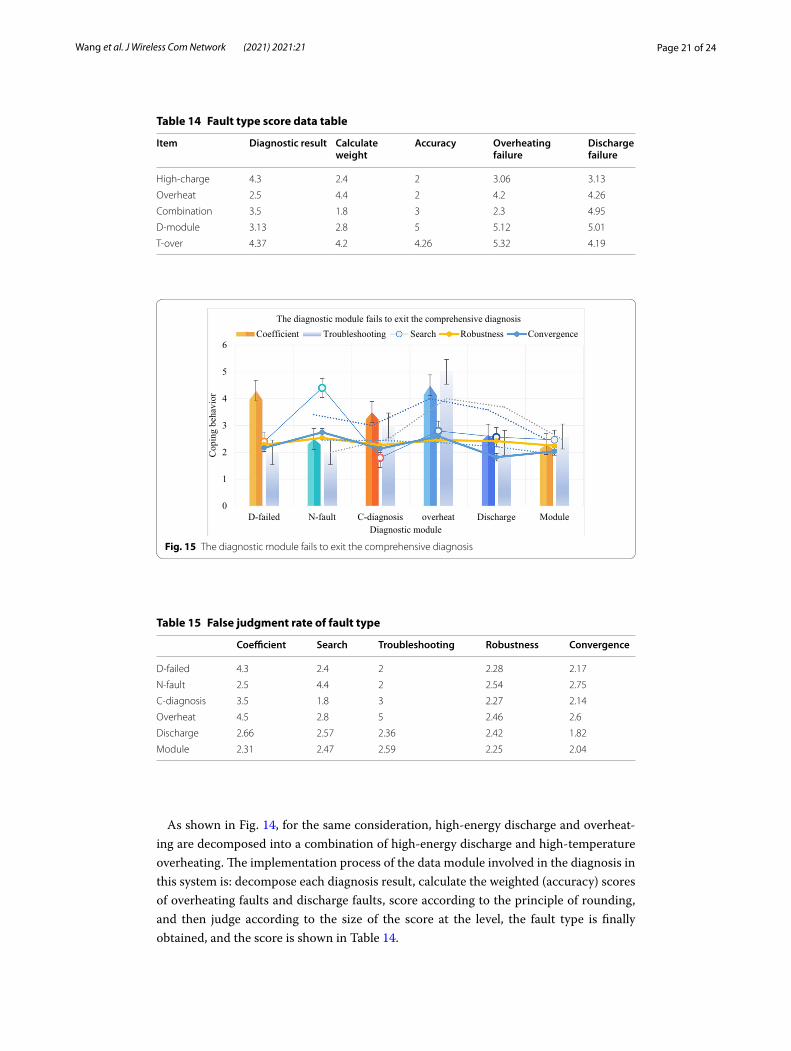
As shown in Fig. 15, if a diagnosis module fails to diagnose (no diagnosis result) or diagnoses no fault, the diagnosis module will automatically exit the comprehensive diag-nosis. In this way, it is easy for two modules to think that there is discharge (or overheat-ing), and only one module thinks that there is both overheating (and discharge), and the diagnosis result will be a discharge and overheating fault. This is mainly considered from the aspect of causing users to pay enough attention.
As shown in Table 15, using the combined diagnosis model to diagnose transformer faults, the misjudgment rate of each fault type is much lower than that of using a sin-gle diagnostic module. It can be seen that the use of the Internet of Things and a series of methods to diagnose power transformer faults is better than traditional diagnostic methods, and can effectively improve the accuracy of fault diagnosis.
5 ConclusionThis paper mainly expounds the combination of Internet of Things and smart grid technology and the role of Internet of Things technology in power maintenance, ana-lyzes the use of power transformer and its fault diagnosis system, and focuses on GPRS communication module and fault diagnosis module in data acquisition termi-nal, and deeply explores transformer fault diagnosis and data management subsystem based on information fusion technology. It can be seen that GPRS communication network combined with Internet of Things technology can effectively diagnose the fault system of power transformer.
The research results of this paper: 30 groups of transformer fault samples are selected, and 10 groups are randomly selected for network training, and the remain-ing samples are used for testing. The transformer fault system diagnosis model is established for each group of power transformers for four consecutive months. This paper studies the detection success rate of power transformer fault diagnosis system model based on the Internet of Things. The training error is less than 0.0001, and it can accurately identify the fault types of non training samples.
Although many scholars have made outstanding achievements in the research of power transformer fault diagnosis system and Internet of Things technology, but at the same time, in view of some limitations of this study, we hope that the Internet of Things and transformer fault diagnosis technology should also consider other prob-lems that are easy to be ignored while meeting the demand, so as to better improve the fault diagnosis technology and more widely use it. If the fault system diagnosis technology can be further improved and applied to power transformer better, it will greatly improve the safety of people’s life.
AbbreviationsPLC: Programmable Logic Controller; SNR: Signal Noise Ratio; IOT: Indexed Organized Table; TCP: Transmission Control Protocol; IP: Internet Protocol; LCD: Liquid crystal display; DC: Direct current; GPRS: General Packet Radio Service.
AcknowledgementsThe authors thank the editor and anonymous reviewers for their helpful comments and valuable suggestions.
Author’s contributionsAll authors take part in the discussion of the work described in this paper. All authors read and approved the final manuscript.
FundingThis work was supported by Digital grid platform (Hainan) construction project (number: 072900HQ42190001).
Page 23 of 24Wang et al. J Wireless Com Network (2021) 2021:21
Consent for publication.Approved.
Competing interestsThere is no potential competitive advantage in our paper. All the authors have reviewed the manuscript and agreed to submit it to your magazine. We confirm that the contents of the manuscript have not been published or submitted for publication elsewhere.
Author details1 Hainan Power Grid Co., Ltd, Haikou 460100, Hainan, China. 2 Hainan Power Grid Co., Ltd., Information Communication Branch, Haikou 460100, Hainan, China.
Received: 2 September 2020 Accepted: 2 December 2020
References 1. M. Di Renzo, W. Lu, System-level analysis/optimization of cellular networks with simultaneous wireless information
and power transfer: stochastic geometry modeling. IEEE Trans. Veh. Technol. 66(3), 1–1 (2017) 2. L. Juanli, X. Jiacheng, Y. Zhaojian et al., Fault diagnosis method for a mine hoist in the internet of things environ-
ment. Sensors 18(6), 1920 (2018) 3. Y. Qian, J. Yan, H. Guan et al., Design of hybrid wireless and power line sensor networks with dual-interface relay in
IoT. IEEE Internet Things J. 6(1), 239–249 (2019) 4. Y.B. Zikria, H. Yu, M.K. Afzal et al., Internet of Things (IoT): operating system, applications and protocols design, and
validation techniques. Future Gen. Comput. Syst. 88, 699–706 (2018) 5. A.M. Zungeru, S. Subashini, P. Vetrivelan, NR-DCSK-based MIMO chaotic communication system: chapter 22, in
Wireless Communication Networks and Internet of Things. Lecture Notes in Electrical Engineering, vol. 493 (2019), pp. 207–215. 10.1007/978-981-10-8663-2
6. A.M. Zungeru, S. Subashini, P. Vetrivelan, Throughput analysis of MacroUE for varied transmit power of small cell in heterogeneous network: chapter 17, in Wireless Communication Networks and Internet of Things. Lecture Notes in Electrical Engineering, vol. 493 (2019), pp. 161–170. 10.1007/978-981-10-8663-2
7. G. Manogaran, N. Chilamkurti, C.H. Hsu, Emerging trends, issues, and challenges in Internet of Medical Things and wireless networks. Pers. Ubiquitous Comput. 22(5–6), 879–882 (2018)
8. M.S. Mahmoud, A.A.H. Mohamad, A study of efficient power consumption wireless communication techniques/modules for Internet of Things (IoT) applications. Adv. Internet Things 06(2), 19–29 (2016)
9. S. Krueger, Critical theory of communication: new readings of Lukács, Adorno, Marcuse, Honneth and Habermas in the age of the internet. Inf. Commun. Soc. 21(11–12), 1808–1812 (2018)
10. A.M. Zungeru, S. Subashini, P. Vetrivelan, Dependency analysis of control parameter configuration on ISD and ran-dom mobility of UE in LTE-A network: chapter 16, in Wireless Communication Networks and Internet of Things. Lecture Notes in Electrical Engineering, vol. 493 (2019), pp. 151–159. 10.1007/978-981-10-8663-2
11. Z. Ma, M. Xiao, Y. Xiao et al., High-reliability and low-latency wireless communication for Internet of Things: chal-lenges, fundamentals and enabling technologies. IEEE Internet Things J. 6, 7946–7970 (2019)
12. A.M. Zungeru, S. Subashini, P. Vetrivelan, Modelling and performance analysis of Wi-fi offloading: chapter 4, in Wire-less Communication Networks and Internet of Things. Lecture Notes in Electrical Engineering, vol. 493 (2019), pp. 33–39. 10.1007/978-981-10-8663-2
13. A.M. Zungeru, S. Subashini, P. Vetrivelan, Enhancement of QOS parameters in cluster-based wireless sensor network using cooperative MIMO: chapter 20, in Wireless Communication Networks and Internet of Things. Lecture Notes in Electrical Engineering, vol. 493 (2019), pp. 187–195. 10.1007/978-981-10-8663-2
14. K.V. Arya, R.S. Bhadoria, N.S. Chaudhari, Realizing the wireless technology in Internet of Things (IoT): chap-ter 10, in Emerging Wireless Communication and Network Technologies (2018), pp. 173–192. https ://doi.org/10.1007/978-981-13-0396-8
15. M.M. Rana, W. Xiang, IoT communications network for wireless power transfer system state estimation and stabiliza-tion. IEEE Internet Things J. 5, 4142–4150 (2018)
16. A. Vinel, Chen W S E, Xiong N N, et al. Enabling wireless communication and networking technologies for the inter-net of things [Guest editorial]. IEEE Wirel. Commun. 2016, 23(5):8–9.
17. A.M. Zungeru, S. Subashini, P. Vetrivelan, Efficient relaying for enhanced network longevity for E-health IOT services in medical body area networks: chapter 2, in Wireless Communication Networks and Internet of Things, Lecture Notes in Electrical Engineering, vol. 493 (2019), pp. 13–19. 10.1007/978-981-10-8663-2
18. P. Ramezani, A. Jamalipour, Toward the evolution of wireless powered communication networks for the future Internet of Things. IEEE Netw. 31(6), 62–69 (2017)
19. W. Ejaz, A. Anpalagan, M.A. Imran et al., Internet of Things (IoT) in 5G wireless communications. IEEE Access 4, 10310–10314 (2017)
20. Z. Junqing, D. Trung, W. Roger et al., Securing wireless communications of the Internet of Things from the physical layer: an overview. Entropy 19(8), 420 (2017)
21. S. Gao, G. Tian, X. Dai et al., A novel distributed linear-spatial-array sensing system based on multichannel LPWAN for large-scale blast wave monitoring. IEEE Internet Things J. 6(6), 9679–9688 (2019)
22. V. Freschi, E. Lattanzi, A study on the impact of packet length on communication in low power wireless sensor networks under interference. IEEE Internet Things J. 6, 3820–3830 (2019)
23. O. Kaiwartya, A.H. Abdullah, Y. Cao et al., Virtualization in wireless sensor networks: fault tolerant embedding for Internet of Things. IEEE Internet Things J. 5(2), 571–580 (2018)
Page 24 of 24Wang et al. J Wireless Com Network (2021) 2021:21
24. P. Hu, J. Zhang, 5G-enabled fault detection and diagnostics: how do we achieve efficiency? IEEE Internet Things J. 7(4), 3267–3281 (2020)
25. G. Yang, D. Yuan, Y.C. Liang et al., Optimal resource allocation in full-duplex ambient backscatter communication networks for wireless-powered IoT. IEEE Internet Things J. 6, 2612–2625 (2018)
Publisher’s NoteSpringer Nature remains neutral with regard to jurisdictional claims in published maps and institutional affiliations.