Embed Size (px)
Citation preview
Power Transformer Protection
Power Transformer Protection
By
Velimir Lackovic, Electrical Engineer
PDHLibrary Course No 02017050
5 PDH HOURS
2
Power Transformer Protection | www.pdhlibrary.com
Power Transformer Protection
The advancement of electrical power systems has been reflected in the developments
in power transformer manufacturing. This has led to a wide range of power
transformers. Their ratings range from a few kVA to several hundred MVA and are
used for a wide variety of applications. Power transformer protection varies with the
application and transformer importance. In the case of a fault within the power
transformer it is important to minimize tripping time in order to decrease the impact of
thermal stress and electrodynamic forces. Distribution power transformers can be
protected by using fuses or overcurrent protection relays. This leads to time-delayed
protection due to downstream co-ordination requirements. Nevertheless, time delayed
short circuit clearance is unacceptable on larger power transformers due to system
operation/stability and cost of repair.
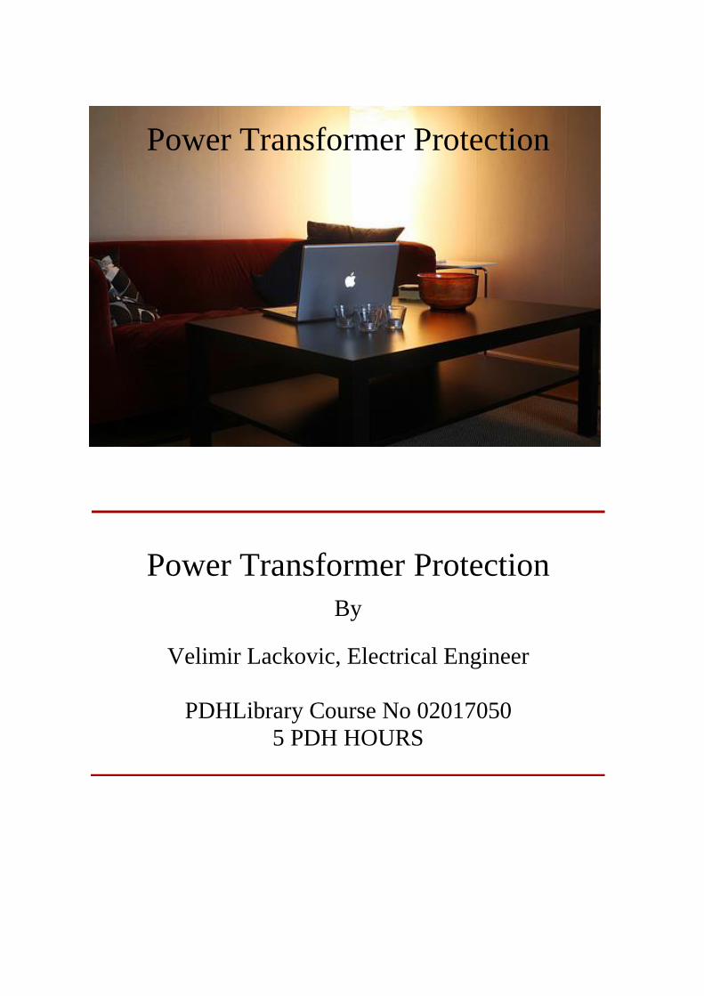
Power transformer short circuits are typically grouped into five categories:
- Winding and terminal short circuits
- Core short circuits
- Tank and transformer accessory short circuits
- On–load tap changer short circuits
- Prolonged or uncleared external short circuits
Summary of short circuit causes initiated in the power transformer itself, is shown in
Figure 1.
Figure 1. Power transformer short circuit statistics
Winding and Terminal Core Tank and Accessories OLTC

3
Power Transformer Protection | www.pdhlibrary.com
TRANSFORMER WINDING FAULTS
A transformer winding fault is limited in magnitude by the following factors:
- source impedance
- neutral grounding impedance
- winding connection arrangement
- fault voltage
- power transformer leakage reactance
Few distinct cases come up and are described below.
STAR-CONNECTED TRANSFORMER WINDING WITH NEUTRAL POINT
GROUNDED THROUGH AN IMPEDANCE
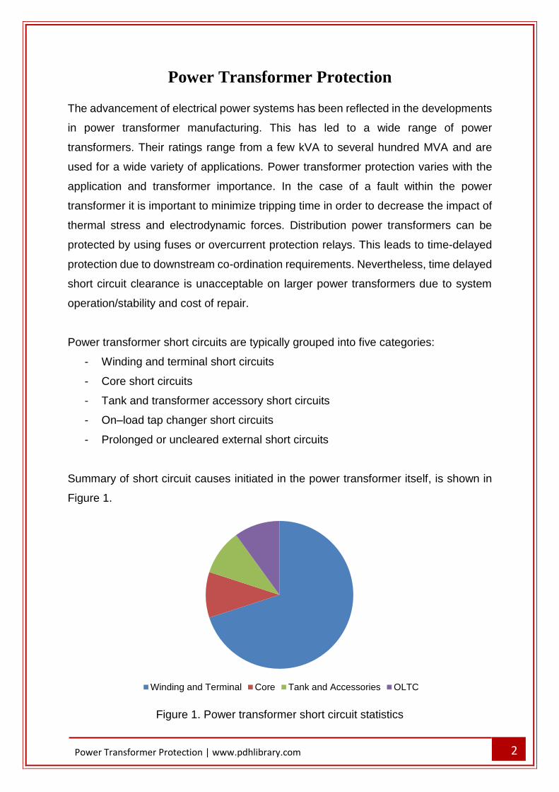
The winding ground fault current depends on the grounding impedance value and is
also directly proportional to the distance of the fault from the transformer neutral point,
since the fault voltage will be directly proportional to this distance. For a fault on a
transformer secondary winding, the matching primary current will depend on the
transformation ratio between the primary winding and the short-circuited secondary
turns. This also changes with fault position, so that the fault current in the transformer
primary winding is directly proportional to the square of the fraction of the winding that
is short-circuited. The case is presented in Figure 2. Faults in the lower third of the
transformer winding generate very little current in the primary winding and that makes
fault detection by primary current measurement challenging.
4
Power Transformer Protection | www.pdhlibrary.com
Figure 2. Ground fault current in resistance grounded star winding
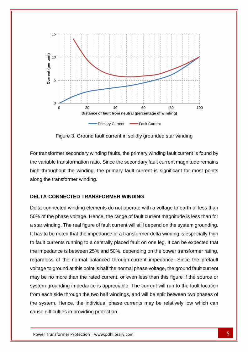
STAR-CONNECTED WINDING WITH NEUTRAL POINT SOLIDLY GROUNDED
The fault current is limited by the leakage reactance of the transformer winding, which
changes in a complex pattern with the fault position. The variable fault point voltage is
also a critical factor, as in the case of impedance grounding. For faults close to the
neutral end of the transformer winding, the reactance is very low, and results in the
greatest fault currents. The variation of current with fault location is presented in Figure
3.
0
10
20
30
40
50
60
70
80
90
100
0 10 20 30 40 50 60 70 80 90 100Pe
rce
nta
ge
of
res
pe
cti
ve
ma
xim
um
s
ing
le p
ha
se
ea
rth
fa
ult
cu
rre
nt
Distance of fault from neutral (percentage of winding)
Fault Current Primary Current
IF
IP
5
Power Transformer Protection | www.pdhlibrary.com
Figure 3. Ground fault current in solidly grounded star winding
For transformer secondary winding faults, the primary winding fault current is found by
the variable transformation ratio. Since the secondary fault current magnitude remains
high throughout the winding, the primary fault current is significant for most points
along the transformer winding.
DELTA-CONNECTED TRANSFORMER WINDING
Delta-connected winding elements do not operate with a voltage to earth of less than
50% of the phase voltage. Hence, the range of fault current magnitude is less than for
a star winding. The real figure of fault current will still depend on the system grounding.
It has to be noted that the impedance of a transformer delta winding is especially high
to fault currents running to a centrally placed fault on one leg. It can be expected that
the impedance is between 25% and 50%, depending on the power transformer rating,
regardless of the normal balanced through-current impedance. Since the prefault
voltage to ground at this point is half the normal phase voltage, the ground fault current
may be no more than the rated current, or even less than this figure if the source or
system grounding impedance is appreciable. The current will run to the fault location
from each side through the two half windings, and will be split between two phases of
the system. Hence, the individual phase currents may be relatively low which can
cause difficulties in providing protection.
0
5
10
15
0 20 40 60 80 100
Cu
rre
nt
(pe
r u
nit
)
Distance of fault from neutral (percentage of winding)
Primary Current Fault Current
6
Power Transformer Protection | www.pdhlibrary.com
PHASE TO PHASE TRANSFORMER FAULTS
Faults between phases within a transformer are relatively uncommon. However, in the
case such fault happens, it will give rise to a significant current comparable to the
ground fault currents.
INTERTURN TRANSFORMER FAULTS
In low voltage transformers, interturn insulation breakdown is unlikely to happen
unless the mechanical force on the winding due to external short circuits has caused
insulation degradation, or insulating oil (if used) has become contaminated by
moisture. A high voltage power transformer connected to an overhead transmission
line will be exposed to steep fronted impulse voltages, developing from lightning
strikes, network faults and switching processes. A line surge, which may be of few
times the nominal system voltage, will concentrate on the transformer winding end
turns because of the high equivalent frequency of the surge front. Part-winding
resonance, involving voltages up to 20 times nominal voltage may happen. The
interturn insulation of the winding end turns is strengthened, but cannot be enhanced
in proportion to the insulation to ground, which is relatively high. Therefore, partial
winding flashover is more likely. The consequent progress of the fault, if not discovered
in the earliest stage, may well destruct the evidence of the real cause.
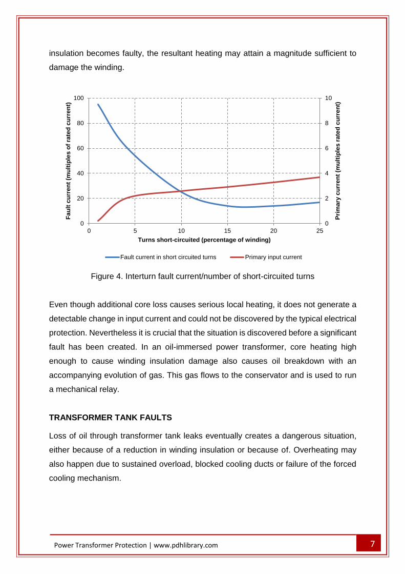
A short circuit of a few turns of the transformer winding will give rise to a big fault
current in the short-circuited loop. However, the terminal currents will be very small,
because of the high ratio of transformation between the whole winding and the short
circuited turns.
The graph in Figure 4 presents the relevant information for a typical transformer of
3.25% impedance with the short circuited turns symmetrically placed in the winding
center.
TRANSFORMER CORE FAULTS
A conducting bridge across the laminated structures of the transformer core can allow
sufficient eddy-currents which can cause serious overheating. The bolts that clamp
the core together are always insulated to prevent this problem. If any part of the core
7
Power Transformer Protection | www.pdhlibrary.com
insulation becomes faulty, the resultant heating may attain a magnitude sufficient to
damage the winding.
Figure 4. Interturn fault current/number of short-circuited turns
Even though additional core loss causes serious local heating, it does not generate a
detectable change in input current and could not be discovered by the typical electrical
protection. Nevertheless it is crucial that the situation is discovered before a significant
fault has been created. In an oil-immersed power transformer, core heating high
enough to cause winding insulation damage also causes oil breakdown with an
accompanying evolution of gas. This gas flows to the conservator and is used to run
a mechanical relay.
TRANSFORMER TANK FAULTS
Loss of oil through transformer tank leaks eventually creates a dangerous situation,
either because of a reduction in winding insulation or because of. Overheating may
also happen due to sustained overload, blocked cooling ducts or failure of the forced
cooling mechanism.
0
2
4
6
8
10
0
20
40
60
80
100
0 5 10 15 20 25
Pri
ma
ry c
urr
en
t (m
ult
iple
s r
ate
d c
urr
en
t)
Fa
ult
cu
rre
nt
(mu
ltip
les
of
rate
d c
urr
en
t)
Turns short-circuited (percentage of winding)
Fault current in short circuited turns Primary input current
8
Power Transformer Protection | www.pdhlibrary.com
EXTERNALLY APPLIED CONSIDERATIONS
Causes of abnormal stress in a power transformer are:
- overload
- system short circuits
- overvoltage
- reduced system frequency
OVERLOAD
Overload creates increased 'copper loss' and a subsequent temperature increase.
Overloads can be tolerated for limited periods and suggestions for oil-immersed power
transformers are provided in IEC 60354.
The transformer thermal time constant of naturally cooled power transformers lies
between 2.5-5 hours. Shorter time constants are applicable for the force-cooled power
transformers.
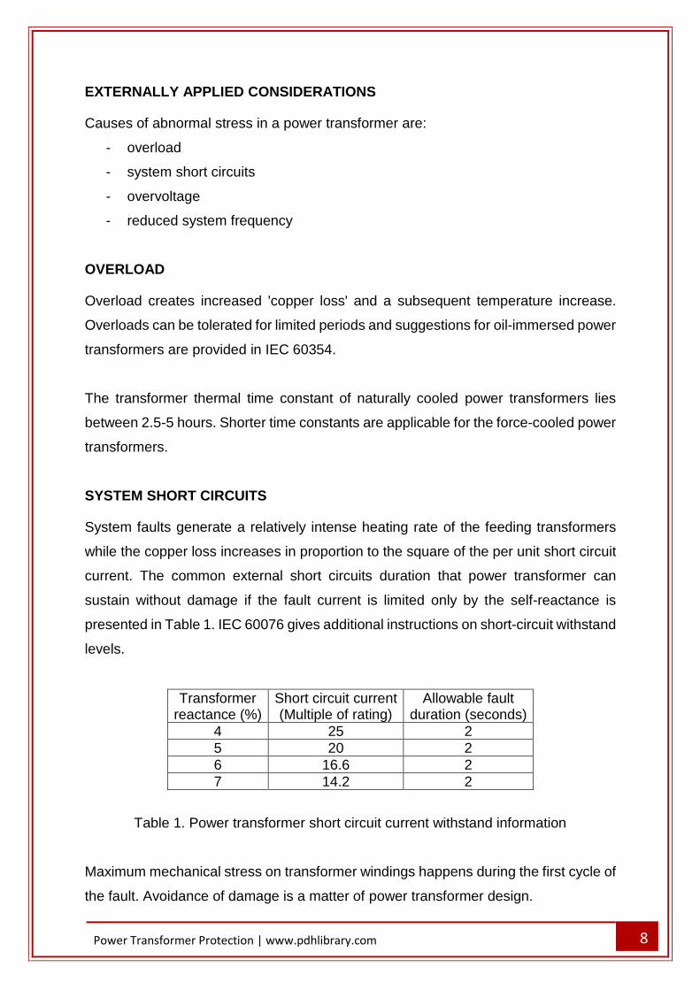
SYSTEM SHORT CIRCUITS
System faults generate a relatively intense heating rate of the feeding transformers
while the copper loss increases in proportion to the square of the per unit short circuit
current. The common external short circuits duration that power transformer can
sustain without damage if the fault current is limited only by the self-reactance is
presented in Table 1. IEC 60076 gives additional instructions on short-circuit withstand
levels.
Transformer reactance (%)
Short circuit current (Multiple of rating)
Allowable fault duration (seconds)
4 25 2
5 20 2
6 16.6 2
7 14.2 2
Table 1. Power transformer short circuit current withstand information
Maximum mechanical stress on transformer windings happens during the first cycle of
the fault. Avoidance of damage is a matter of power transformer design.
9
Power Transformer Protection | www.pdhlibrary.com
OVERVOLTAGES
Overvoltage situations are of two kinds:
- transient surge voltages
- power frequency overvoltage
Transient overvoltages develop from faults, switching, and lightning disturbances.
They are liable to cause interturn faults. These overvoltages are typically fixed by
shunting the high voltage terminals to ground either with a plain rod gap or by surge
diverters, which constitute a stack of short gaps in series with a non-linear resistor.
The surge diverter, in contrast to the rod gap, has the advantage of eliminating the
flow of power current after discharging a surge. In this way it prevents subsequent
transformer isolation.
Power frequency overvoltage causes both an increase in insulation stress and a
proportionate working flux increase. The second effect increases both the iron loss
and magnetising current. In addition, flux is diverted from the laminated core into
structural steel elements. The core bolts, which typically carry little flux, may be
exposed to a high flux diverted from the greatly saturated region of core alongside.
This ends in a rapid temperature rise in the bolts, damaging their and coil insulation.
REDUCED SYSTEM FREQUENCY
System frequency reduction affects flux density. Transformer can function with some
degree of overvoltage with a matching increase in frequency, but transformer service
must not be extended with a high voltage input at a low frequency. Service cannot be
maintained when the ratio of voltage to frequency, with these quantities expressed in
per unit of their rated values, exceeds unity by more than a small number, for example
if V/f >1.1. If a significant increase in system voltage has been taken care of in the
transformer design stage, the base of 'unit voltage' should be taken as the greatest
voltage for which the power transformer is designed.
TRANSFORMER MAGNETISING INRUSH
The process of magnetising inrush is a transient condition that primarily happens when
a power transformer is energised. It is not a fault condition, and hence transformer
10
Power Transformer Protection | www.pdhlibrary.com
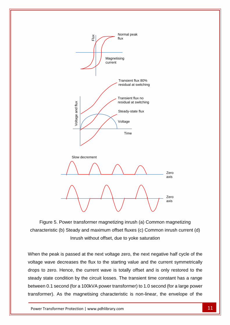
protection must stay stable during the inrush transient. Figure 5(a) presents a power
transformer magnetizing characteristic. To minimize costs, weight and size, power
transformers are typically operated near to the ‘knee point’ of the magnetising curve.
Accordingly, only a small raise in core flux above normal working levels will end in a
great magnetising current. Under normal steady-state conditions, the magnetising
current related with the operating flux level is relatively small, as presented in Figure
5(b). Nevertheless, if a power transformer winding is energized at a voltage zero, with
no remanent flux, the flux level during the first voltage cycle (2 x normal flux) will end
in core saturation and a great non-sinusoidal magnetizing current waveform, as
presented in Figure 5(c). This current is known as magnetising inrush current and may
remain for few cycles. Few factors impact the magnitude and magnetising current
inrush duration:
- point on wave switching
- residual flux – worst-case conditions end in the flux peak value achieving 280%
of normal value
- number of banked power transformers
- transformer design and rating
- system short circuit current level
The big flux densities mentioned above are so far beyond the normal working range
that the incremental relative permeability of the core approximates to unity and the
inductance of the transformer winding falls to a figure near that of the 'aircored'
inductance. The current wave, starting from zero, increases slowly at first. The flux
has a value just above the residual value and the permeability of the core being fairly
big. As the flux passes the normal working value and enters the greatly saturated
portion of the magnetizing curve, the inductance decreases and the current quickly
rises to a peak that may be 500% of the steady state magnetizing current.
11
Power Transformer Protection | www.pdhlibrary.com
Figure 5. Power transformer magnetizing inrush (a) Common magnetizing
characteristic (b) Steady and maximum offset fluxes (c) Common inrush current (d)
Inrush without offset, due to yoke saturation
When the peak is passed at the next voltage zero, the next negative half cycle of the
voltage wave decreases the flux to the starting value and the current symmetrically
drops to zero. Hence, the current wave is totally offset and is only restored to the
steady state condition by the circuit losses. The transient time constant has a range
between 0.1 second (for a 100kVA power transformer) to 1.0 second (for a large power
transformer). As the magnetising characteristic is non-linear, the envelope of the
Zero axis
Zero axis
Slow decrement
Time
Vo
lta
ge
and
flu
x
Voltage
Steady-state flux
Transient flux no
residual at switching
Transient flux 80%
residual at switching
Magnetising current
Normal peak flux F
lux
12
Power Transformer Protection | www.pdhlibrary.com
transient current is not purely of exponential form. It can be noted that the magnetising
current changes up to 30 minutes after switching on. Even though right choice of the
point on the wave for a single– phase power transformer will result in no transient
inrush, mutual effects ensure that a transient inrush happens in all phases for three-
phase power transformers.
INRUSH WAVEFORM HARMONIC CONTENT
The power transformer magnetising current waveform contains a proportion of
harmonics that increments as the peak flux density is raised to the saturating condition.
The transformer magnetising current contains a third harmonic and increasingly
smaller amounts of fifth and higher harmonics. If the saturation degree is progressively
increased, not only will the harmonic content increment as a whole, but the relative
proportion of fifth harmonic will increase and finally outmatch the third harmonic. At a
higher level the seventh would overcome the fifth harmonic but this needs a degree of
saturation that will not be experienced with power transformers.
The energising conditions that end in an offset inrush current create a waveform that
is asymmetrical. Such a wave commonly comprises both even and odd harmonics.
Common inrush currents contain significant amounts of second and third harmonics
and diminishing amounts of higher orders. As with the steady state wave, the
proportion of harmonics changes with the saturation degree, so that as a dangerous
inrush transient decays, the harmonic makeup of the current goes through a range of
conditions.
POWER TRANSFORMER OVERHEATING
The power transformer rating is based on the temperature increase above an assumed
maximum ambient temperature. Sustained overload is not typically allowable under
this condition. Certain degree of sustained overload can be tolerated at a lower
ambient temperature. Short-term overloads are also allowable to an extent dependent
on the previous loading conditions. IEC 60354 standard gives assistance in this
respect. The only true statement is that the transformer winding must not overheat.
Temperature of about 95°C is conceived as the normal maximum working value
beyond which an additional increase of 8°- 10°C, if maintained, will halve the
13
Power Transformer Protection | www.pdhlibrary.com
transformer insulation life. Hence, overload protection is based on winding
temperature, which is typically measured by a thermal image technique. Protection is
set to trip the power transformer if excessive temperature is achieved. The trip signal
is typically routed via a digital input of a protection relay on one side of the power
transformer, with both alarm and trip facilities made available through programmable
logic in the protection relay. Intertripping between protection relays on the two sides
of the power transformer is typically used to ensure total disconnection of the
transformer. Winding temperature protection may be part of a overall monitoring
package.
OVERVIEW OF THE POWER TRANSFORMER PROTECTION
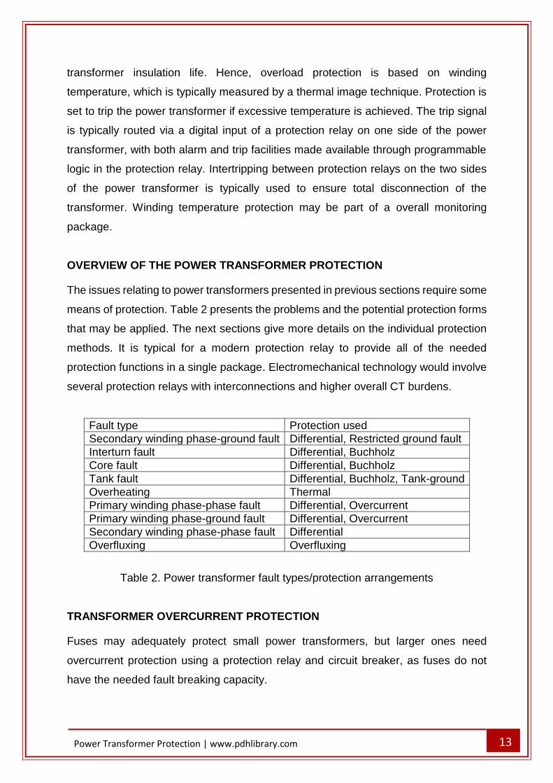
The issues relating to power transformers presented in previous sections require some
means of protection. Table 2 presents the problems and the potential protection forms
that may be applied. The next sections give more details on the individual protection
methods. It is typical for a modern protection relay to provide all of the needed
protection functions in a single package. Electromechanical technology would involve
several protection relays with interconnections and higher overall CT burdens.
Fault type Protection used
Secondary winding phase-ground fault Differential, Restricted ground fault
Interturn fault Differential, Buchholz
Core fault Differential, Buchholz
Tank fault Differential, Buchholz, Tank-ground
Overheating Thermal
Primary winding phase-phase fault Differential, Overcurrent
Primary winding phase-ground fault Differential, Overcurrent
Secondary winding phase-phase fault Differential
Overfluxing Overfluxing
Table 2. Power transformer fault types/protection arrangements
TRANSFORMER OVERCURRENT PROTECTION
Fuses may adequately protect small power transformers, but larger ones need
overcurrent protection using a protection relay and circuit breaker, as fuses do not
have the needed fault breaking capacity.
14
Power Transformer Protection | www.pdhlibrary.com
FUSES
Fuses typically protect small distribution transformers up to ratings of 1MVA at
distribution voltages. In many situations no circuit breaker is provided, making fuse
protection the only available way of automatic isolation. The fuse must have a rating
well above the maximum power transformer load current to resist the short duration
overloads that may happen. Also, the fuses must resist the magnetising inrush
currents taken when power transformers are energised. High Rupturing Capacity
(HRC) fuses, even though very fast in operation with huge fault currents, are super
slow with currents of less than three times their nominal value. Such fuses will do little
to protect the power transformer, serving only to protect the system by disconnecting
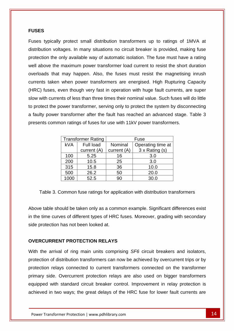
a faulty power transformer after the fault has reached an advanced stage. Table 3
presents common ratings of fuses for use with 11kV power transformers.
Transformer Rating Fuse
kVA Full load current (A)
Nominal current (A)
Operating time at 3 x Rating (s)
100 5.25 16 3.0
200 10.5 25 3.0
315 15.8 36 10.0
500 26.2 50 20.0
1000 52.5 90 30.0
Table 3. Common fuse ratings for application with distribution transformers
Above table should be taken only as a common example. Significant differences exist
in the time curves of different types of HRC fuses. Moreover, grading with secondary
side protection has not been looked at.
OVERCURRENT PROTECTION RELAYS
With the arrival of ring main units comprising SF6 circuit breakers and isolators,
protection of distribution transformers can now be achieved by overcurrent trips or by
protection relays connected to current transformers connected on the transformer
primary side. Overcurrent protection relays are also used on bigger transformers
equipped with standard circuit breaker control. Improvement in relay protection is
achieved in two ways; the great delays of the HRC fuse for lower fault currents are
15
Power Transformer Protection | www.pdhlibrary.com
averted and ground-fault tripping element is provided in addition to the overcurrent
element. The time delay curve should be selected to discriminate with circuit protection
on the transformer secondary side. A high-set instantaneous protection relay element
is typically provided, the current setting being selected to avoid operation for a
secondary short circuit. This allows high-speed clearance of primary terminal short
circuits.
RESTRICTED EARTH FAULT PROTECTION
Conventional ground fault protection using overcurrent devices fails to give proper
protection for power transformer windings. This is especially true for a star-connected
winding with an impedance-grounded neutral. The protection degree is considerably
improved by the usage of restricted earth fault protection (or REF protection). This is
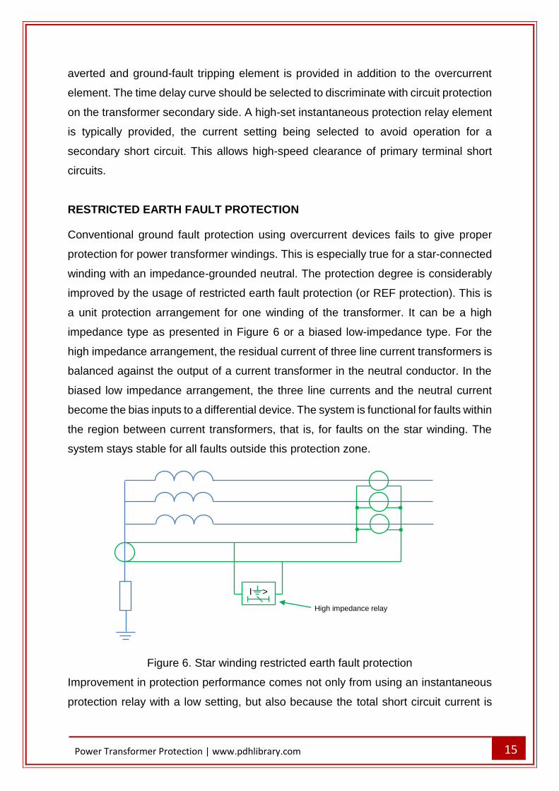
a unit protection arrangement for one winding of the transformer. It can be a high
impedance type as presented in Figure 6 or a biased low-impedance type. For the
high impedance arrangement, the residual current of three line current transformers is
balanced against the output of a current transformer in the neutral conductor. In the
biased low impedance arrangement, the three line currents and the neutral current
become the bias inputs to a differential device. The system is functional for faults within
the region between current transformers, that is, for faults on the star winding. The
system stays stable for all faults outside this protection zone.
Figure 6. Star winding restricted earth fault protection
Improvement in protection performance comes not only from using an instantaneous
protection relay with a low setting, but also because the total short circuit current is
I >
High impedance relay
16
Power Transformer Protection | www.pdhlibrary.com
measured, not only the transformed component in the transformer HV primary winding
(if the star winding is a secondary winding). Restricted earth fault protection is usually
used even when the neutral is solidly grounded. Since short circuit current then stays
at a high value even to the last turn of the transformer winding, nearly complete cover
for ground faults is achieved. This is an improvement in comparison with the
performance of systems that do not measure the neutral conductor current.
Ground fault protection use for delta-connected or ungrounded star winding is
inherently restricted, since no zero sequence components can be transferred through
the transformer to the other windings. Both transformer windings can be separately
protected with restricted earth fault protection. This arrangement provides high speed
protection against ground faults for the complete transformer with relatively simple
equipment. A high impedance relay is applied, allowing fast operation and phase fault
stability.
TRANSFORMER DIFFERENTIAL PROTECTION
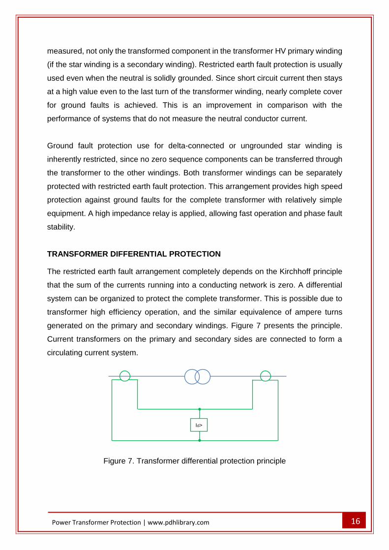
The restricted earth fault arrangement completely depends on the Kirchhoff principle
that the sum of the currents running into a conducting network is zero. A differential
system can be organized to protect the complete transformer. This is possible due to
transformer high efficiency operation, and the similar equivalence of ampere turns
generated on the primary and secondary windings. Figure 7 presents the principle.
Current transformers on the primary and secondary sides are connected to form a
circulating current system.
Figure 7. Transformer differential protection principle
Id>
17
Power Transformer Protection | www.pdhlibrary.com
TRANSFORMER DIFFERENTIAL PROTECTION BASIC CONSIDERATIONS
A variety of considerations have to be kept in mind when applying the principles of
differential protection to power transformers. These considerations include:
- the possible occurrence of overfluxing
- the impacts of the variety of grounding and winding arrangements (filtering of
zero sequence currents)
- correction for potential phase shift across the transformer windings (phase
correction)
- the impact of magnetising inrush during initial start
- correction for potential unbalance of signals from current transformers on either
side of the transformer windings (ratio correction)
In traditional transformer differential arrangements, the demands for phase and ratio
correction were met by the application of external interposing current transformers
(ICTs) or by a delta connection of the main CTs to give phase correction.
Digital/numerical protection relays use ratio and phase correction. It is implemented
through the software and enables most combinations of transformer winding schemes,
irrespective of the winding connections of the primary CTs. It does not need the
additional space and cost requirements of hardware interposing CTs.
LINE CURRENT TRANSFORMER PRIMARY RATINGS
Line current transformers have primary ratings chosen to be about same as nominal
currents of the transformer windings to which they are applied. Primary ratings will
typically be fixed to those of available standard ratio CTs.
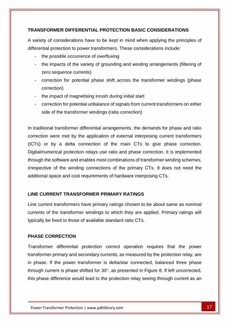
PHASE CORRECTION
Transformer differential protection correct operation requires that the power
transformer primary and secondary currents, as measured by the protection relay, are
in phase. If the power transformer is delta/star connected, balanced three phase
through current is phase shifted for 30°, as presented in Figure 8. If left uncorrected,
this phase difference would lead to the protection relay seeing through current as an
18
Power Transformer Protection | www.pdhlibrary.com
unbalanced fault current, and result in relay operation. Phase correction must be
applied.
Figure 8. Differential protection for two-winding delta/star power transformer
Electromechanical and static protection relays use adequate CT/ICT connections to
assure that the primary and secondary currents transferred to the protection relay are
in phase. For digital and numerical protection relays, it is typical to use star connected
line CTs on all transformer windings and compensate for the winding phase shift using
software. Depending on protection relay design, the only information needed in such
circumstances may be the transformer vector group. Phase compensation is then
automatically completed. Caution is needed if such protection relay is used to replace
an existing electromechanical or static relay since the primary and secondary line CTs
may not have the same winding arrangement. In such situations, phase compensation
and related protection relay data entry needs more detailed consideration.
Occasionally, the available phase compensation facilities cannot accommodate the
power transformer winding connection. Interposing CTs must be used in such
situations.
A
B
C
Id> Id> Id>
19
Power Transformer Protection | www.pdhlibrary.com
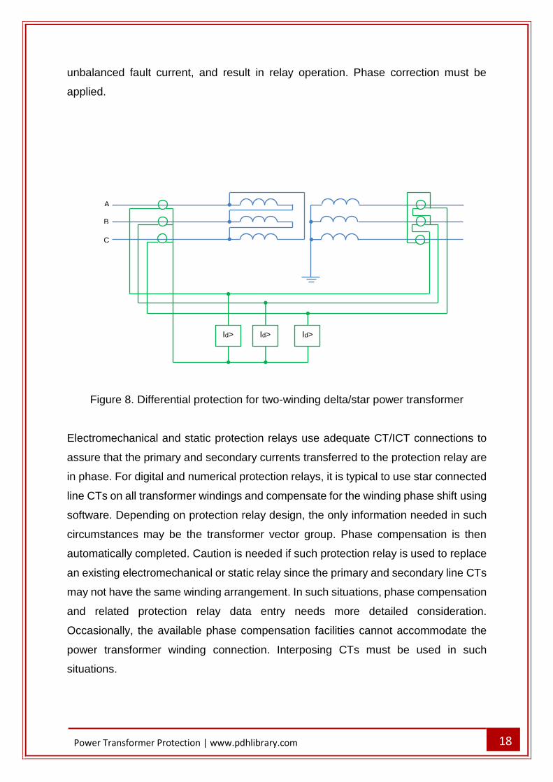
ZERO SEQUENCE CURRENT FILTERING
It is important to provide some method of zero sequence filtering when a transformer
winding can pass zero sequence current to an external ground fault. This is to ensure
that out-of-zone ground faults are not detected by the power transformer protection as
an in-zone fault. This is accomplished by use of delta-connected line CTs or
interposing CTs for older protection relays. The winding connection of the line and/or
interposing CTs must take this into consideration, in addition to any necessary phase
compensation. For digital/numerical protection relays, the required filtering is provided
in the protection relay software. Table 4 presents the phase compensation and zero
sequence filtering requirements.
Transformer Connection
Transformer Phase Shift
Clock face
vector
Phase compensation
needed
HV Zero Sequence Filtering
LV Zero Sequence Filtering
Yy0
0° 0° 0°
Yes Yes
Zd0 Yes
Dz0 Yes
Dd0
Yz1 Zy1
30° 1 30°
Yes Yes
Yd1 Yes
Dy1 Yes
Yy6
180° 1 180°
Yes Yes
Zd6 Yes
Dz6 Yes
Dd6
Yz11 Zy11
30° 11 30°
Yes Yes
Yd11 Yes
Dy11 Yes
YyH YzH
(H/12)x360° Hour ‘H’
-(H/12)x360°
Yes Yes
YdH ZdH Yes
DzH DyH Yes
DdH
Table 4. Current transformer connection for power transformers of different vector
groups
RATIO CORRECTION
Correct service of the differential element demands that currents in the differential
element balance under load and through fault conditions. As the primary and
secondary line CT ratios may not precisely match the power transformer rated winding
currents, digital/numerical protection relays are provided with ratio correction factors
20
Power Transformer Protection | www.pdhlibrary.com
for each of the CT inputs. The correction factors may be automatically computed by
the protection relay from knowledge of the line CT ratios and the transformer MVA
rating. Nevertheless, if interposing CTs are applied, ratio correction may not be simple
task and may need to consider a factor of √3 if delta-connected CTs or ICTs are
involved. If the power transformer is equipped with a tap changer, line CT ratios and
correction factors are typically selected to reach current balance at the mid tap of the
power transformer. It is mandatory to ensure that current mismatch due to off-nominal
tap service will not cause spurious operation.
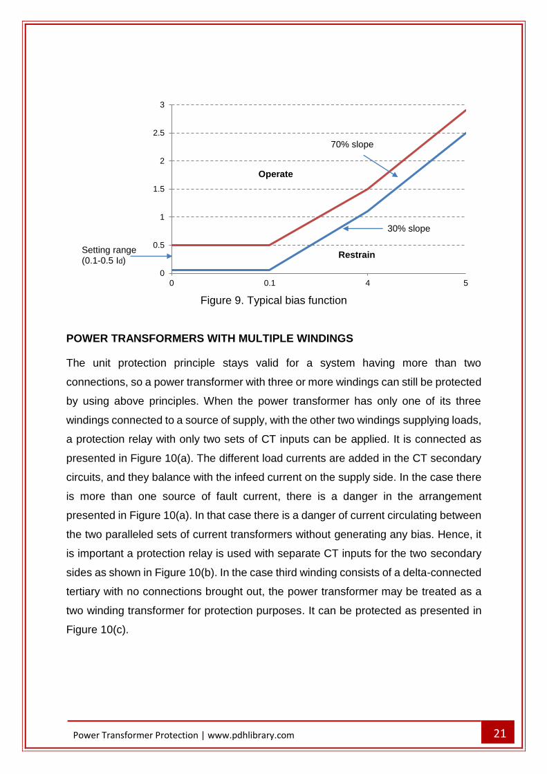
BIAS SETTING
Bias is used for transformer differential protection for the same reasons as any unit
protection arrangement – to give stability for external faults while allowing sensitive
settings to pick up internal faults. The situation is more complex if a tap changer is
present. With line CT/ICT ratios and correction factors set to reach current balance at
nominal tap, an off-nominal tap may be perceived by the differential protection as an
internal fault. By choosing the minimum bias to be higher than sum of the maximum
tap of the power transformer and possible CT errors, malfunctioning due to this cause
is averted. Some protection relays use a bias characteristic with three parts, as
presented in Figure 9. The first part is set higher than the transformer magnetising
current. The second part is set to allow for off-nominal tap settings, while the third part
has bigger bias slope beginning well above nominal current to cater for heavy through-
fault situations.
21
Power Transformer Protection | www.pdhlibrary.com
Figure 9. Typical bias function
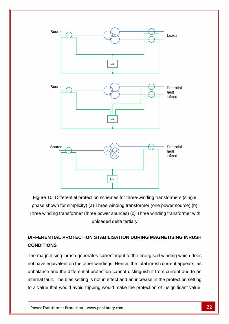
POWER TRANSFORMERS WITH MULTIPLE WINDINGS
The unit protection principle stays valid for a system having more than two
connections, so a power transformer with three or more windings can still be protected
by using above principles. When the power transformer has only one of its three
windings connected to a source of supply, with the other two windings supplying loads,
a protection relay with only two sets of CT inputs can be applied. It is connected as
presented in Figure 10(a). The different load currents are added in the CT secondary
circuits, and they balance with the infeed current on the supply side. In the case there
is more than one source of fault current, there is a danger in the arrangement
presented in Figure 10(a). In that case there is a danger of current circulating between
the two paralleled sets of current transformers without generating any bias. Hence, it
is important a protection relay is used with separate CT inputs for the two secondary
sides as shown in Figure 10(b). In the case third winding consists of a delta-connected
tertiary with no connections brought out, the power transformer may be treated as a
two winding transformer for protection purposes. It can be protected as presented in
Figure 10(c).
0
0.5
1
1.5
2
2.5
3
0 0.1 4 5
Operate
Restrain
70% slope
30% slope
Setting range (0.1-0.5 Id)
22
Power Transformer Protection | www.pdhlibrary.com
Figure 10. Differential protection schemes for three-winding transformers (single
phase shown for simplicity) (a) Three winding transformer (one power source) (b)
Three winding transformer (three power sources) (c) Three winding transformer with
unloaded delta tertiary
DIFFERENTIAL PROTECTION STABILISATION DURING MAGNETISING INRUSH
CONDITIONS
The magnetising inrush generates current input to the energised winding which does
not have equivalent on the other windings. Hence, the total inrush current appears, as
unbalance and the differential protection cannot distinguish it from current due to an
internal fault. The bias setting is not in effect and an increase in the protection setting
to a value that would avoid tripping would make the protection of insignificant value.
Id>
Loads Source
Id>
Potential fault infeed
Source
Id>
Potential fault infeed
Source
23
Power Transformer Protection | www.pdhlibrary.com
Therefore methods of delaying, restraining or blocking the differential device must be
applied to prevent protection mal-operation.
TIME DELAY
Since the process is transient, stability can be kept by implementing a small time delay.
However, the method is no longer used since this time delay also delays functioning
of the protection relay in the event of a fault happening at switch-on.
HARMONIC RESTRAINT
Although the inrush current typically resembles an in-zone fault current, it differs a lot
once the waveforms are compared. The waveform difference can be applied to
distinguish between these conditions. As previously mentioned, the inrush current
contains all harmonic orders, but not all of them are equally suited for providing bias.
In reality, only the second harmonic is used since it is present in all inrush waveforms.
The ratio of second harmonic changes with the degree of saturation of the core, but is
always present as long as the uni-directional component of flux exists. The amount
changes depending on the transformer design. Normal fault currents do not contain
second or other even harmonics. Also, distorted currents flowing in saturated iron
cored coils under steady state conditions do not contain second harmonics. Current
transformer output current that is energized into steady state saturation will contain
odd harmonics but not even harmonics. Nevertheless, should the current transformer
be saturated by the transient component of the fault current, the resulting saturation is
not symmetrical and even harmonics are introduced into the output current. This can
enhance the through fault stability performance of a differential protection relay.
Hence, the second harmonic is an attractive basis for a stabilizing bias against inrush
effects. However, care has to be taken to ensure that the current transformers are
large enough so that the harmonics generated by transient saturation do not delay
protection relay normal operation. The differential current is transferred through a filter
that pulls out the second harmonic. This component is then used to generate a
restraining quantity sufficient to overcome the operating tendency due to the whole of
the inrush current that runs in the operating circuit. Sensitive and high-speed system
can be obtained by using this principle.
24
Power Transformer Protection | www.pdhlibrary.com
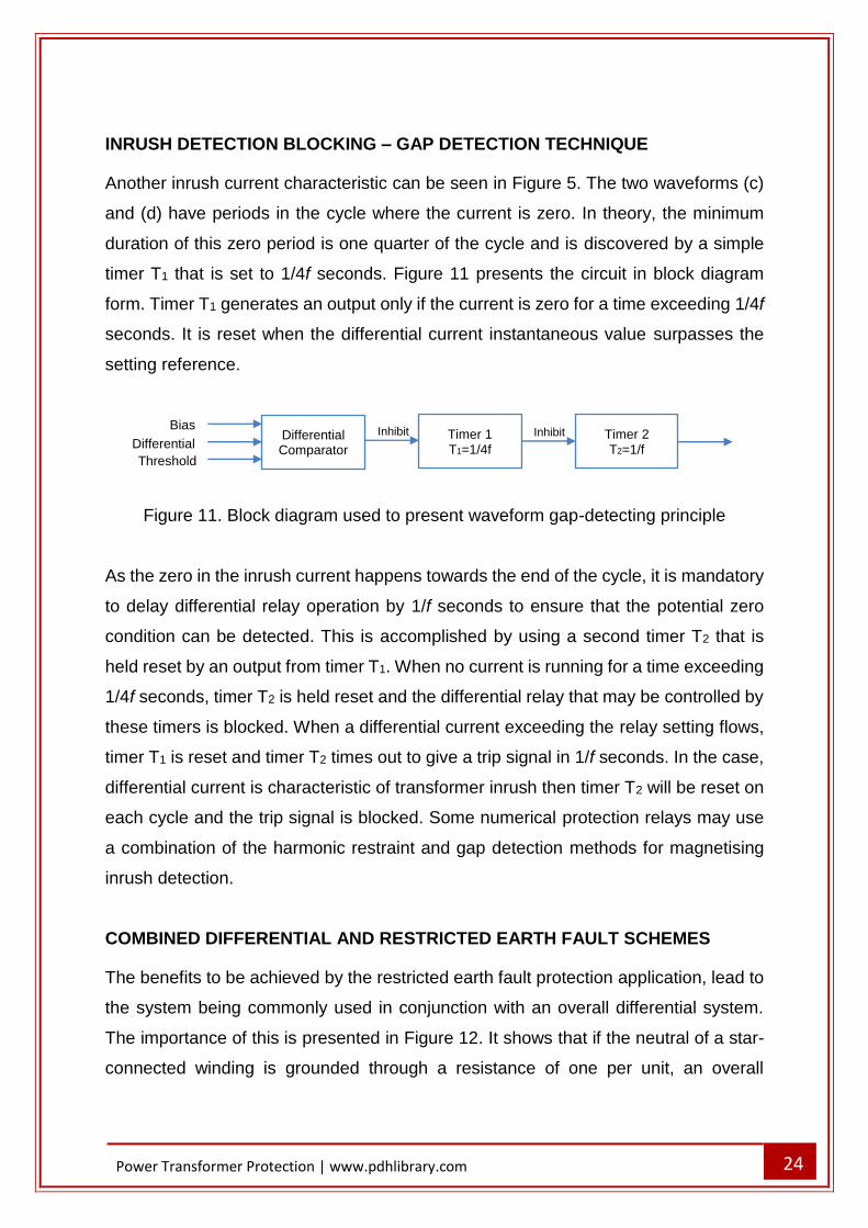
INRUSH DETECTION BLOCKING – GAP DETECTION TECHNIQUE
Another inrush current characteristic can be seen in Figure 5. The two waveforms (c)
and (d) have periods in the cycle where the current is zero. In theory, the minimum
duration of this zero period is one quarter of the cycle and is discovered by a simple
timer T1 that is set to 1/4f seconds. Figure 11 presents the circuit in block diagram
form. Timer T1 generates an output only if the current is zero for a time exceeding 1/4f
seconds. It is reset when the differential current instantaneous value surpasses the
setting reference.
Figure 11. Block diagram used to present waveform gap-detecting principle
As the zero in the inrush current happens towards the end of the cycle, it is mandatory
to delay differential relay operation by 1/f seconds to ensure that the potential zero
condition can be detected. This is accomplished by using a second timer T2 that is
held reset by an output from timer T1. When no current is running for a time exceeding
1/4f seconds, timer T2 is held reset and the differential relay that may be controlled by
these timers is blocked. When a differential current exceeding the relay setting flows,
timer T1 is reset and timer T2 times out to give a trip signal in 1/f seconds. In the case,
differential current is characteristic of transformer inrush then timer T2 will be reset on
each cycle and the trip signal is blocked. Some numerical protection relays may use
a combination of the harmonic restraint and gap detection methods for magnetising
inrush detection.
COMBINED DIFFERENTIAL AND RESTRICTED EARTH FAULT SCHEMES
The benefits to be achieved by the restricted earth fault protection application, lead to
the system being commonly used in conjunction with an overall differential system.
The importance of this is presented in Figure 12. It shows that if the neutral of a star-
connected winding is grounded through a resistance of one per unit, an overall
Differential Comparator
Timer 1 T1=1/4f
Timer 2 T2=1/f
Bias
Differential
Threshold
Inhibit Inhibit
25
Power Transformer Protection | www.pdhlibrary.com
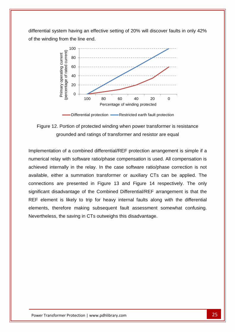
differential system having an effective setting of 20% will discover faults in only 42%
of the winding from the line end.
Figure 12. Portion of protected winding when power transformer is resistance
grounded and ratings of transformer and resistor are equal
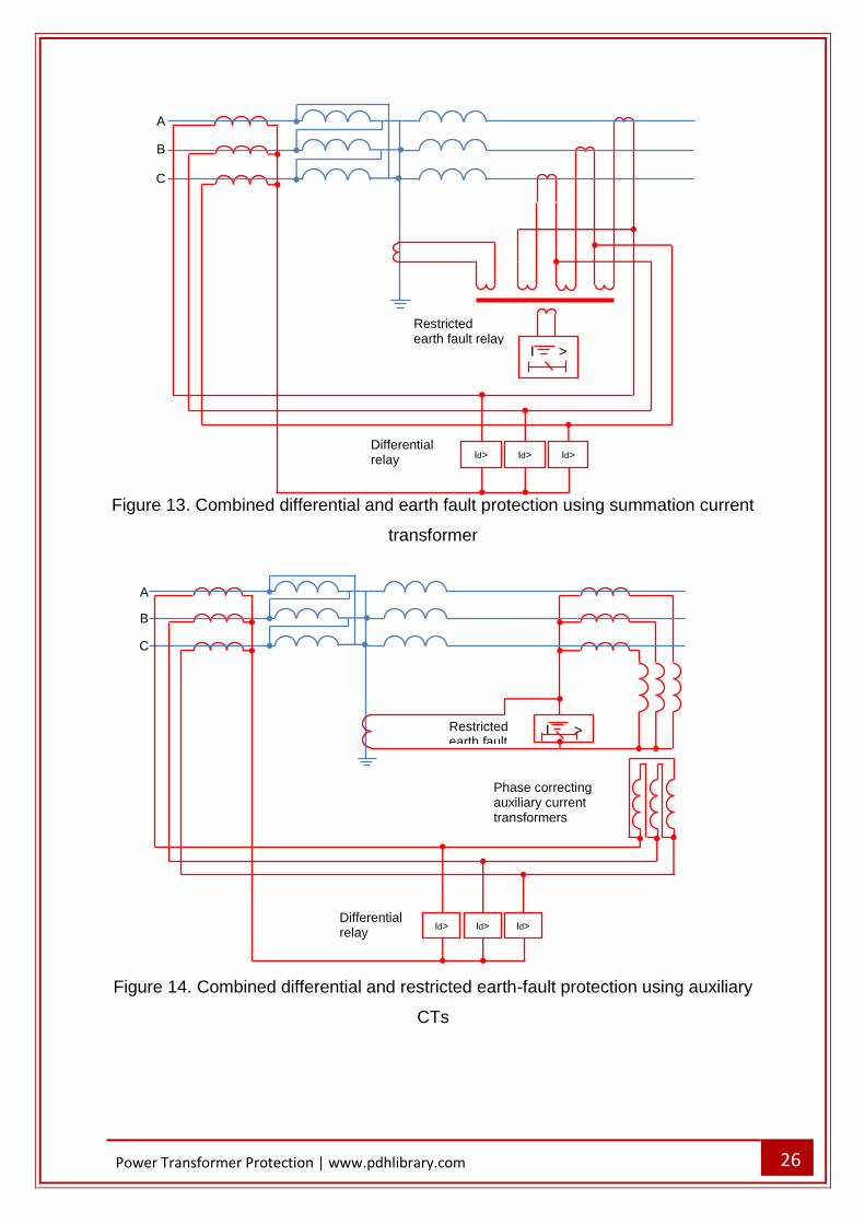
Implementation of a combined differential/REF protection arrangement is simple if a
numerical relay with software ratio/phase compensation is used. All compensation is
achieved internally in the relay. In the case software ratio/phase correction is not
available, either a summation transformer or auxiliary CTs can be applied. The
connections are presented in Figure 13 and Figure 14 respectively. The only
significant disadvantage of the Combined Differential/REF arrangement is that the
REF element is likely to trip for heavy internal faults along with the differential
elements, therefore making subsequent fault assessment somewhat confusing.
Nevertheless, the saving in CTs outweighs this disadvantage.
0
20
40
60
80
100
100 80 60 40 20 0
Prim
ary
opera
ting c
urr
ent
(perc
enta
ge o
f ra
ted c
urr
ent)
Percentage of winding protected
Differential protection Restricted earth fault protection
26
Power Transformer Protection | www.pdhlibrary.com
Figure 13. Combined differential and earth fault protection using summation current
transformer
Figure 14. Combined differential and restricted earth-fault protection using auxiliary
CTs
Phase correcting auxiliary current transformers
Restricted earth fault
I >
Id> Id> Id>
A
B
C
Differential relay
Restricted earth fault relay
I >
Id> Id> Id>
A
B
C
Differential relay
27
Power Transformer Protection | www.pdhlibrary.com
APPLICATION WHEN AN EARTHING TRANSFORMER IS CONNECTED WITHIN
THE PROTECTED ZONE
A delta-connected winding cannot transfer any zero sequence current to ground fault
on the connected system. Any current that does flow is in consequence of the
grounded neutral elsewhere on the system and will have a 2-1-1 pattern of current
distribution between phases. When the power transformer represents a major power
feed, the system may be grounded at that point by an earthing transformer or earthing
reactor. They are frequently used in the system, close to the main supply transformer
and within the transformer protection zone. Zero sequence current that runs through
the earthing transformer during system ground faults will run through the line current
transformers on this side, and, without an equivalent current in the balancing current
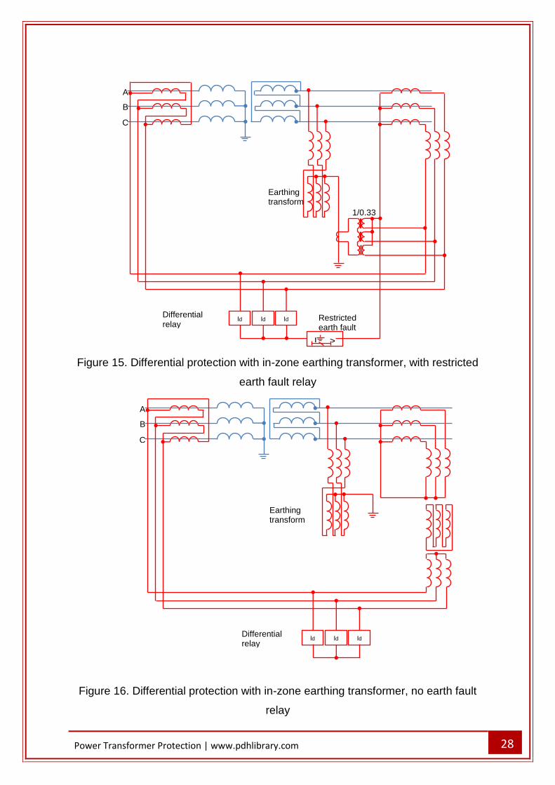
transformers, will cause unwanted tripping of the relays. The problem can be resolved
by subtracting the appropriate component of current from the main CT output. The
earthing transformer neutral current is utilized for this purpose. Since this represents
three times the zero sequence current, ratio correction is needed. This can take the
form of interposing CT’s of ratio 1/0.333, put to subtract their output from that of the
line current transformers in each phase, as presented in Figure 15. The zero sequence
component is cancelled, restoring balance to the differential system. Alternatively,
numerical protection relays may use software to complete the subtraction, having
computed the zero sequence component internally.
A high impedance protection relay device can be connected in the neutral lead
between current transformers and differential relays to give restricted earth fault
protection to the winding. As an alternative to the above arrangement, the circulating
current system can be accomplished via a three-phase group of interposing
transformers that are provided with tertiary windings connected in delta. This winding
short-circuits the zero sequence component and removes it from the balancing
quantities in the relay circuit. Arrangement is shown in Figure 16. Provided restricted
earth fault protection is not needed, the arrangement presented in Figure 16 has the
benefit of not needing a current transformer. The arrangement can also be connected
as presented in Figure 17 in situations when restricted earth fault protection is needed.
28
Power Transformer Protection | www.pdhlibrary.com
Figure 15. Differential protection with in-zone earthing transformer, with restricted
earth fault relay
Figure 16. Differential protection with in-zone earthing transformer, no earth fault
relay
Id>
Id>
Id>
Earthing transformer
A
B
C
Differential relay
I >
Id>
Id>
Id>
Earthing transformer
A
B
C
Differential relay
Restricted earth fault relay
1/0.33
29
Power Transformer Protection | www.pdhlibrary.com
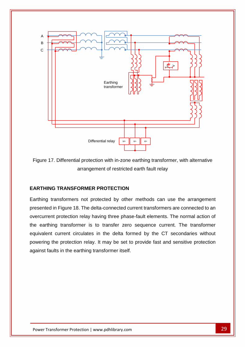
Figure 17. Differential protection with in-zone earthing transformer, with alternative
arrangement of restricted earth fault relay
EARTHING TRANSFORMER PROTECTION
Earthing transformers not protected by other methods can use the arrangement
presented in Figure 18. The delta-connected current transformers are connected to an
overcurrent protection relay having three phase-fault elements. The normal action of
the earthing transformer is to transfer zero sequence current. The transformer
equivalent current circulates in the delta formed by the CT secondaries without
powering the protection relay. It may be set to provide fast and sensitive protection
against faults in the earthing transformer itself.
Id> Id> Id>
I >
Earthing transformer
A
B
C
Differential relay
30
Power Transformer Protection | www.pdhlibrary.com
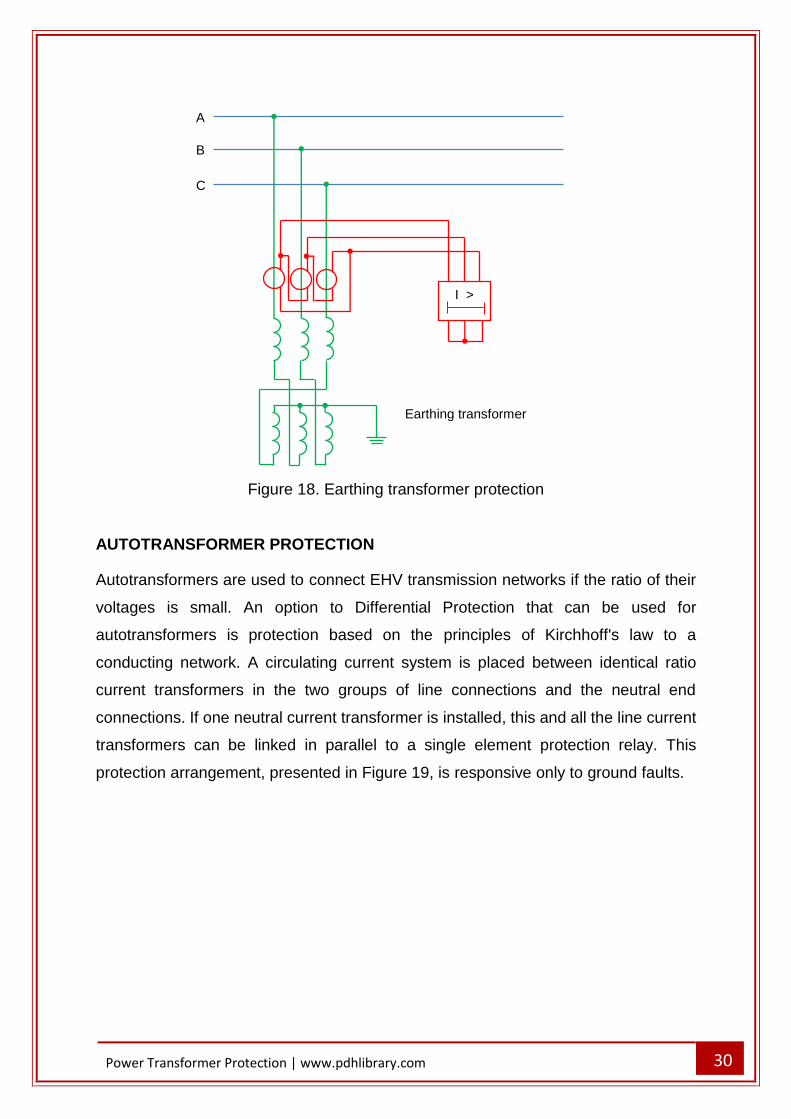
Figure 18. Earthing transformer protection
AUTOTRANSFORMER PROTECTION
Autotransformers are used to connect EHV transmission networks if the ratio of their
voltages is small. An option to Differential Protection that can be used for
autotransformers is protection based on the principles of Kirchhoff's law to a
conducting network. A circulating current system is placed between identical ratio
current transformers in the two groups of line connections and the neutral end
connections. If one neutral current transformer is installed, this and all the line current
transformers can be linked in parallel to a single element protection relay. This
protection arrangement, presented in Figure 19, is responsive only to ground faults.
A
B
C
Earthing transformer
I >
31
Power Transformer Protection | www.pdhlibrary.com
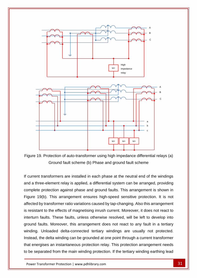
Figure 19. Protection of auto-transformer using high impedance differential relays (a)
Ground fault scheme (b) Phase and ground fault scheme
If current transformers are installed in each phase at the neutral end of the windings
and a three-element relay is applied, a differential system can be arranged, providing
complete protection against phase and ground faults. This arrangement is shown in
Figure 19(b). This arrangement ensures high-speed sensitive protection. It is not
affected by transformer ratio variations caused by tap-changing. Also this arrangement
is resistant to the effects of magnetising inrush current. Moreover, it does not react to
interturn faults. These faults, unless otherwise resolved, will be left to develop into
ground faults. Moreover, this arrangement does not react to any fault in a tertiary
winding. Unloaded delta-connected tertiary windings are usually not protected.
Instead, the delta winding can be grounded at one point through a current transformer
that energises an instantaneous protection relay. This protection arrangement needs
to be separated from the main winding protection. If the tertiary winding earthing lead
Id> Id>
A
B
C
Id>
a
b
c
Id>
A
B
C
High
impedance
relay
32
Power Transformer Protection | www.pdhlibrary.com
is linked to the main winding neutral above the neutral current transformer in an
attempt to make a combined system, there could be ‘blind spots’ which the protection
cannot reach and cover.
TRANSFORMER OVERFLUXING PROTECTION
Transformer overfluxing primarily happens due to following system conditions:
- low system frequency
- high system voltage
- geomagnetic disturbances
Geomagnetic disturbances result in low frequency ground currents circulating through
a transmission system. Since momentary system disturbances can cause transient
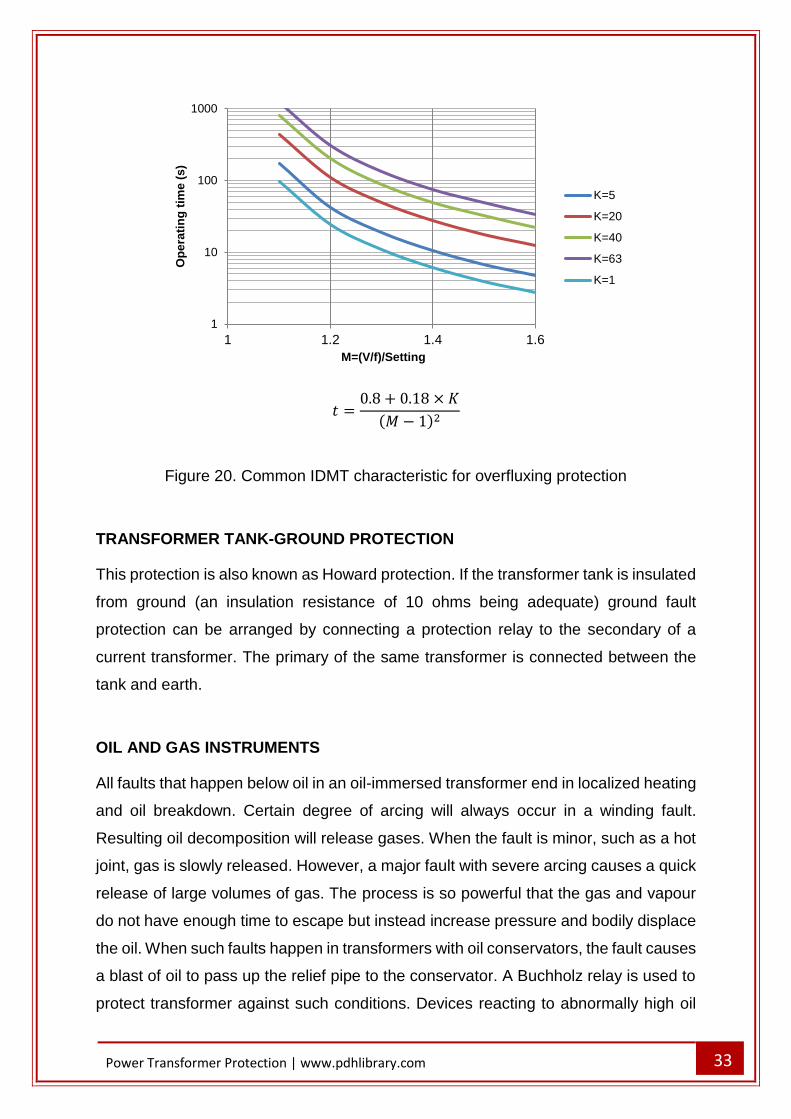
overfluxing that is not critical, time delayed tripping is needed. The normal protection
is an IDMT or definite time curve, started if a set V/f threshold is surpassed. Frequently,
separate alarm and trip elements are given. The alarm function would be definite time-
delayed and the trip function would be an IDMT characteristic. A common
characteristic is presented in Figure 20. Geomagnetic disturbances may cause
overfluxing without the V/f threshold being surpassed. Some protection relays provide
a 5th harmonic detection feature, which can be utilized to discover such situation, as
levels of this harmonic increase under overfluxing conditions.
33
Power Transformer Protection | www.pdhlibrary.com
𝑡 =0.8 + 0.18 × 𝐾
(𝑀 − 1)2
Figure 20. Common IDMT characteristic for overfluxing protection
TRANSFORMER TANK-GROUND PROTECTION
This protection is also known as Howard protection. If the transformer tank is insulated
from ground (an insulation resistance of 10 ohms being adequate) ground fault
protection can be arranged by connecting a protection relay to the secondary of a
current transformer. The primary of the same transformer is connected between the
tank and earth.
OIL AND GAS INSTRUMENTS
All faults that happen below oil in an oil-immersed transformer end in localized heating
and oil breakdown. Certain degree of arcing will always occur in a winding fault.
Resulting oil decomposition will release gases. When the fault is minor, such as a hot
joint, gas is slowly released. However, a major fault with severe arcing causes a quick
release of large volumes of gas. The process is so powerful that the gas and vapour
do not have enough time to escape but instead increase pressure and bodily displace
the oil. When such faults happen in transformers with oil conservators, the fault causes
a blast of oil to pass up the relief pipe to the conservator. A Buchholz relay is used to
protect transformer against such conditions. Devices reacting to abnormally high oil
1
10
100
1000
1 1.2 1.4 1.6
Op
era
tin
g t
ime
(s
)
M=(V/f)/Setting
K=5
K=20
K=40
K=63
K=1
34
Power Transformer Protection | www.pdhlibrary.com
pressure or rate-of-rise of oil pressure are also available and may be applied together
with a Buchholz relay.
OIL PRESSURE RELIEF INSTRUMENTS
The simplest pressure relief device is the widely adopted ‘frangible disc’. It is usually
installed at the end of an oil relief pipe protruding from the transformer tank top. The
surge of oil caused by a severe fault bursts the disc, letting the oil to quickly discharge.
Relieving and limiting the pressure rise prevents explosive rupture of the tank and
subsequent fire risk. Outdoor oil-immersed power transformers are frequently installed
in a catchment pit to collect and contain spilt oil, thereby minimising the possibility of
pollution. A drawback of the frangible disc is that the oil remaining in the transformer
tank is left exposed to the atmosphere after rupture. This can be avoided using more
effective device, the sudden pressure relief valve. This device opens to allow
discharge of oil if the pressure exceeds a predetermined level, but closes automatically
as soon as the internal pressure drops below preset level. If the abnormal pressure is
rather high, the valve can function within a few milliseconds, and provide quick tripping
when suitable contacts are fitted. The device is usually installed in power transformers
rated at 2MVA or higher. Also it can be used for distribution transformers rated as low
as 200kVA, especially those placed in hazardous locations.
SUDDEN PRESSURE RISE RELAY
This relay observes pressure rise rather than absolute pressure and thereby can react
even faster than the pressure relief valve to sudden abnormally high pressures.
Precision as low as 0.07bar/s is achievable, but when installed in forced-cooled
transformers the operating speed of the device may have to be deliberately slowed to
avoid spurious tripping during circulation pump starts. Optionally, fast pressure rise
relays may have their output monitored by instantaneous high-set overcurrent
elements.
BUCHHOLZ PROTECTION
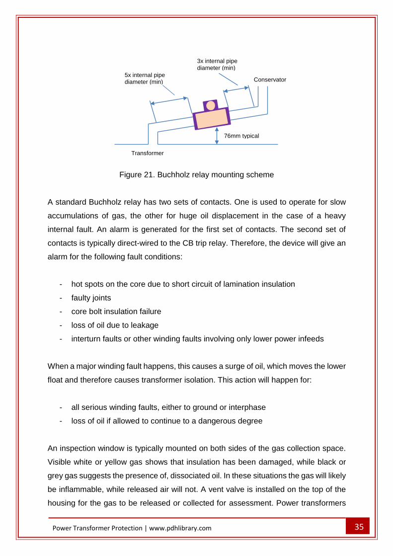
Buchholz protection is typically installed on all power transformers equipped with a
conservator. The Buchholz relay is placed in a cast housing which is connected in the
pipe to the conservator, as presented in Figure 21.
35
Power Transformer Protection | www.pdhlibrary.com
Figure 21. Buchholz relay mounting scheme
A standard Buchholz relay has two sets of contacts. One is used to operate for slow
accumulations of gas, the other for huge oil displacement in the case of a heavy
internal fault. An alarm is generated for the first set of contacts. The second set of
contacts is typically direct-wired to the CB trip relay. Therefore, the device will give an
alarm for the following fault conditions:
- hot spots on the core due to short circuit of lamination insulation
- faulty joints
- core bolt insulation failure
- loss of oil due to leakage
- interturn faults or other winding faults involving only lower power infeeds
When a major winding fault happens, this causes a surge of oil, which moves the lower
float and therefore causes transformer isolation. This action will happen for:
- all serious winding faults, either to ground or interphase
- loss of oil if allowed to continue to a dangerous degree
An inspection window is typically mounted on both sides of the gas collection space.
Visible white or yellow gas shows that insulation has been damaged, while black or
grey gas suggests the presence of, dissociated oil. In these situations the gas will likely
be inflammable, while released air will not. A vent valve is installed on the top of the
housing for the gas to be released or collected for assessment. Power transformers
Conservator
Transformer
76mm typical
5x internal pipe diameter (min)
3x internal pipe diameter (min)
36
Power Transformer Protection | www.pdhlibrary.com
with forced oil circulation may face oil flow to/from the conservator on starting/stopping
of the pumps. The Buchholz relay must not function in these situations. Cleaning
procedures may cause oil aeration. During these situations, transformer tripping due
to Buchholz operation should be inhibited for an adequate period.
Because of its universal response to faults within the power transformer, some of
which are hard to discover by other means, the Buchholz relay is invaluable, whether
regarded as a main protection or as an addition to other protection arrangements.
Tests completed by striking a high voltage arc in a transformer tank filled with oil, have
indicated that tripping times of 0.05-0.1s are achievable. Electrical protection is
typically also used, either to achieve faster operation for major faults, or because
Buchholz relays have to be stopped from tripping during oil maintenance intervals.
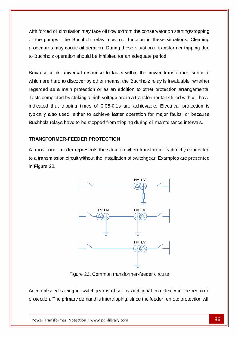
TRANSFORMER-FEEDER PROTECTION
A transformer-feeder represents the situation when transformer is directly connected
to a transmission circuit without the installation of switchgear. Examples are presented
in Figure 22.
Figure 22. Common transformer-feeder circuits
Accomplished saving in switchgear is offset by additional complexity in the required
protection. The primary demand is intertripping, since the feeder remote protection will
HV LV
HV LV LV HV
HV LV
37
Power Transformer Protection | www.pdhlibrary.com
not react to the low current fault conditions. These conditions can be discovered by
restricted earth fault and Buchholz protections. Either unrestricted or restricted
protection can be used. Next, the transformer-feeder can be protected as a single zone
or used with separate protections for the feeder and the transformer. In the second
case, the separate protections can both be unit type systems. An adequate option is
the combination of transformer unit protection with an unrestricted system of feeder
protection, including an intertripping feature.
NON-UNIT ARRANGEMENTS
The next sections present how non-unit arrangements are used to protect power
transformer-feeders against various fault types.
TRANSFORMER FEEDER PHASE AND GROUND FAULTS
High-speed protection against phase and ground faults can be accomplished by
distance protection relays installed at the end of the feeder. The transformer
represents considerable lumped impedance. Hence, it is possible to set a distance
relay zone to protect the whole feeder and reach part way into the transformer
impedance. Even though the distance zone is represented as being set ’half way into
the transformer’, it must not be considered that half the transformer winding will be
protected. The implications of autotransformer actions and changes in the resulting
winding impedance prevent this. Protected part of the winding beyond the terminals is
very small. The protection is practically limited to the feeder, which gets high-speed
protection.
FEEDER PHASE FAULTS
A distance protection is not impacted by varying fault levels on the high voltage
busbars. Hence, it is the best arrangement in the case fault level may vary. In
situations where the fault level is rather constant, similar protection can be achieved
using high set instantaneous overcurrent protection relays. These relays should have
a low transient overreach (t), expressed as:
𝐼𝑆 − 𝐼𝐹
𝐼𝐹× 100%
38
Power Transformer Protection | www.pdhlibrary.com
Where:
𝐼𝑆 − setting current
𝐼𝐹 − steady state r.m.s value of the fault current, which when completely offset, just
triggers the protection relay. The instantaneous overcurrent protection relays must be
set without risk of them tripping for faults on the transformer remote side. Referring to
Figure 23, the required setting to ensure that the protection relay will not trip for a fully
offset fault IF2 is expressed as:
𝐼𝑆 = 1.2(1 + 𝑡)𝐼𝐹2
where IF2 is the fault current under maximum source conditions, which happens when
ZS is minimum. The factor of 1.2 takes into account potential errors in the system
impedance and relay and CT errors. Since it is preferable for the instantaneous
overcurrent protection to clear all phase faults anywhere within the feeder under
varying system operating conditions, it is mandatory to have a protection relay setting
less than IF1 to ensure fast and reliable operation. Let us define setting ratio resulting
from setting Is as:
𝑟 =𝐼𝑠
𝐼𝐹1
Hence,
𝑟𝐼𝐹1 = 1.2(1 + 𝑡)𝐼𝐹2
Therefore,
𝑟 = 1.2(1 + 𝑡)𝑍𝑆 + 𝑍𝐿
𝑍𝑆 + 𝑍𝐿 + 𝑍𝑇
= 1.2(1 + 𝑡)𝑍𝑆 + 𝑍𝐿
(1 + 𝑥)(𝑍𝑆 + 𝑍𝐿)
=1.2(1 + 𝑡)
1 + 𝑥
Where:
𝑥 =𝑍𝑇
𝑍𝑆 + 𝑍𝐿
39
Power Transformer Protection | www.pdhlibrary.com
Setting ratio 𝑟 =𝐼𝑆
𝐼𝐹1
Transient over-reach (%) 5 25 50 100
𝑥 =𝑍𝑇
𝑍𝑆 + 𝑍𝐿
0.25 1.01 1.20 1.44 1.92
0.5 0.84 1.00 1.20 1.60
1.0 0.63 0.75 0.90 1.20
2.0 0.42 0.50 0.60 0.80
4.0 0.25 0.30 0.36 0.48
8.0 0.14 0.17 0.20 0.27
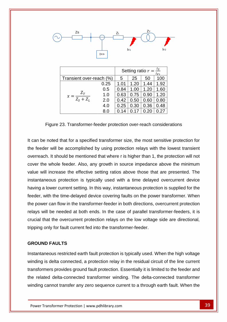
Figure 23. Transformer-feeder protection over-reach considerations
It can be noted that for a specified transformer size, the most sensitive protection for
the feeder will be accomplished by using protection relays with the lowest transient
overreach. It should be mentioned that where r is higher than 1, the protection will not
cover the whole feeder. Also, any growth in source impedance above the minimum
value will increase the effective setting ratios above those that are presented. The
instantaneous protection is typically used with a time delayed overcurrent device
having a lower current setting. In this way, instantaneous protection is supplied for the
feeder, with the time-delayed device covering faults on the power transformer. When
the power can flow in the transformer-feeder in both directions, overcurrent protection
relays will be needed at both ends. In the case of parallel transformer-feeders, it is
crucial that the overcurrent protection relays on the low voltage side are directional,
tripping only for fault current fed into the transformer-feeder.
GROUND FAULTS
Instantaneous restricted earth fault protection is typically used. When the high voltage
winding is delta connected, a protection relay in the residual circuit of the line current
transformers provides ground fault protection. Essentially it is limited to the feeder and
the related delta-connected transformer winding. The delta-connected transformer
winding cannot transfer any zero sequence current to a through earth fault. When the
Zs ZL ZT
IF2 IF1
I>>
40
Power Transformer Protection | www.pdhlibrary.com
feeder is associated with grounded star-connected winding, normal restricted earth
fault protection cannot be used because of the remoteness of the transformer neutral.
Restricted protection can be used using a directional earth fault protection relay. A
simple sensitive and high-speed directional device can be applied, but care has to be
taken for the element transient stability. Optionally, a directional IDMT protection relay
can be applied but the time multiplier has to be set low. The slight inverse time delay
in operation will ensure that unwanted transient operation is avoided. When the supply
source is on the high voltage star side, an optional arrangement that does not need a
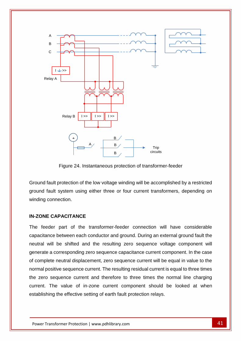
voltage transformer can be applied. The arrangement is presented in Figure 24. For
the circuit breaker to trip, both protection relays A and B must function. That will
happen for ground faults on the feeder or transformer winding.
External ground faults cause the power transformer to deliver only zero sequence
current. It will circulate in the closed delta connection of the secondary windings of the
three auxiliary current transformers. Output is not available to protection relay B.
Through phase faults will trigger relay B, but not the residual relay A. Relay B must
have a setting above the maximum load. Since the grounding of the neutral at a
receiving point is likely to be solid, the ground fault current will be comparable with the
phase fault current. Therefore, high settings are not a serious limitation.
41
Power Transformer Protection | www.pdhlibrary.com
Figure 24. Instantaneous protection of transformer-feeder
Ground fault protection of the low voltage winding will be accomplished by a restricted
ground fault system using either three or four current transformers, depending on
winding connection.
IN-ZONE CAPACITANCE
The feeder part of the transformer-feeder connection will have considerable
capacitance between each conductor and ground. During an external ground fault the
neutral will be shifted and the resulting zero sequence voltage component will
generate a corresponding zero sequence capacitance current component. In the case
of complete neutral displacement, zero sequence current will be equal in value to the
normal positive sequence current. The resulting residual current is equal to three times
the zero sequence current and therefore to three times the normal line charging
current. The value of in-zone current component should be looked at when
establishing the effective setting of earth fault protection relays.
A
+
Trip circuits
B
B
B
A
B
C
I >>
Relay A
I >> I >> I >> Relay B
42
Power Transformer Protection | www.pdhlibrary.com
UNIT ARRANGEMENTS
The major differences between the demands of feeder and transformer protections lie
in the limitation imposed on the transfer of ground fault current by the transformer and
the need for transformer high sensitivity protection. This implies that the two
components of a transformer-feeder connection should be separately protected. This
means installation of current transformers adjacent to, or on, the transformer high
voltage terminals. Separate current transformers are needed for the feeder and
transformer protections so that these can be organized in two separate overlapping
zones. The application of common current transformers is possible, but may involve
the application of auxiliary current transformers, or relay special winding and
connection arrangements. Intertripping of the remote circuit breaker from the
transformer protection will be required, but this can be accomplished using the
communication facilities of the feeder protection relays. Even though technically
dominant, the application of different protection systems is rarely justifiable in
comparison with an overall system or a combination of non-unit feeder protection and
a unit transformer system. An overall unit system must consider the fact that zero
sequence current on one side of a transformer may not be reproduced in any form on
the other side. This introduces little trouble to a modern numerical relay using software
phase/zero sequence compensation and digital communications to transmit complete
information on the phase and ground currents from one relay to the other.
Nevertheless, it does create a more challenging problem for protection relays using
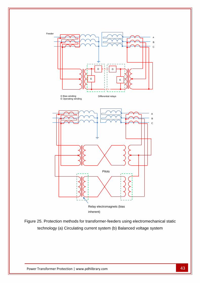
older technology. The line current transformers can be connected to a summation
transformer with unequal taps, as presented in Figure 25(a). This scheme generates
an output for phase faults and also some response for A and B phase-ground faults.
Nevertheless, the resulting settings will be similar to those for phase faults and no
protection will be given for C phase earth faults. An optional arrangement is presented
in Figure 25(b). The B phase is taken through a separate winding on another
transformer or protection relay electromagnet, to create another balancing system.
The two power transformers are connected with their counterparts at the other end of
the feeder-transformer by four pilot wires. Service with three pilot cores is possible but
four are preferred, requiring insignificant increase in pilot cost.
43
Power Transformer Protection | www.pdhlibrary.com
Figure 25. Protection methods for transformer-feeders using electromechanical static
technology (a) Circulating current system (b) Balanced voltage system
E
A
B
C
E
Differential relays
Feeder
D Bias winding E Operating winding
D D
A
B
C
Pilots
Relay electromagnets (bias
inherent)
44
Power Transformer Protection | www.pdhlibrary.com
INTERTRIPPING
To make sure that both the high and low voltage circuit breakers trip for faults within
the transformer and feeder, it is mandatory to operate both circuit breakers from
protection typically associated with one. The technique for accomplishing this is known
as intertripping. The requirement for intertripping on transformer-feeders is based on
the fact that certain fault types generate insufficient current to operate the protection
associated with one of the circuit breakers. These faults are:
- Transformer faults that operate the Buchholz relay and trip the local low voltage
circuit breaker. However, these faults fail to generate sufficient fault current to
operate the protection related with the remote high voltage circuit breaker
- Ground faults on the transformer star winding, which, because of the position
of the fault in the winding, again cannot generate sufficient current for relay
operation at the remote circuit breaker
- Ground faults on the feeder or high voltage delta connected winding which only
trip the high voltage circuit breaker. However, the transformer is left energised
form the low voltage side and with two high voltage phases at near line-to-line
voltage above ground. Intermittent arcing may happen and there is a chance of
transient overvoltage happening and causing a further insulation breakdown.
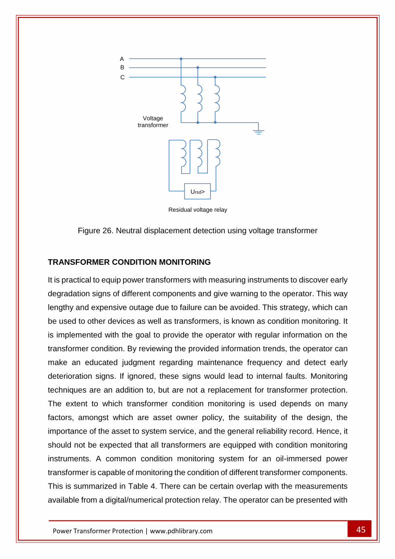
NEUTRAL DISPLACEMENT
An alternative to intertripping is to find the condition by measuring the residual voltage
on the feeder. Ground fault happening on the feeder connected to an unearthed
transformer winding should be cleared by the feeder circuit. In the case there is a
source of supply on the transformer secondary side, the feeder may be still energized.
The feeder will then be a local unearthed system, and, if the ground fault continues in
an arcing condition, severe overvoltages may happen. A voltage protection relay is
energised from the broken-delta connected secondary winding of a voltage
transformer on the high voltage line. It gets an input proportional to the zero sequence
voltage of the line. Arrangement is shown in Figure 26. The protection relay typically
receives zero voltage, but, in the case of ground fault, the broken-delta voltage will
rise to three times the phase voltage. Ground faults elsewhere in the system may also
result in displacement of the neutral. Therefore, discrimination is accomplished using
definite or inverse time characteristics.
45
Power Transformer Protection | www.pdhlibrary.com
Figure 26. Neutral displacement detection using voltage transformer
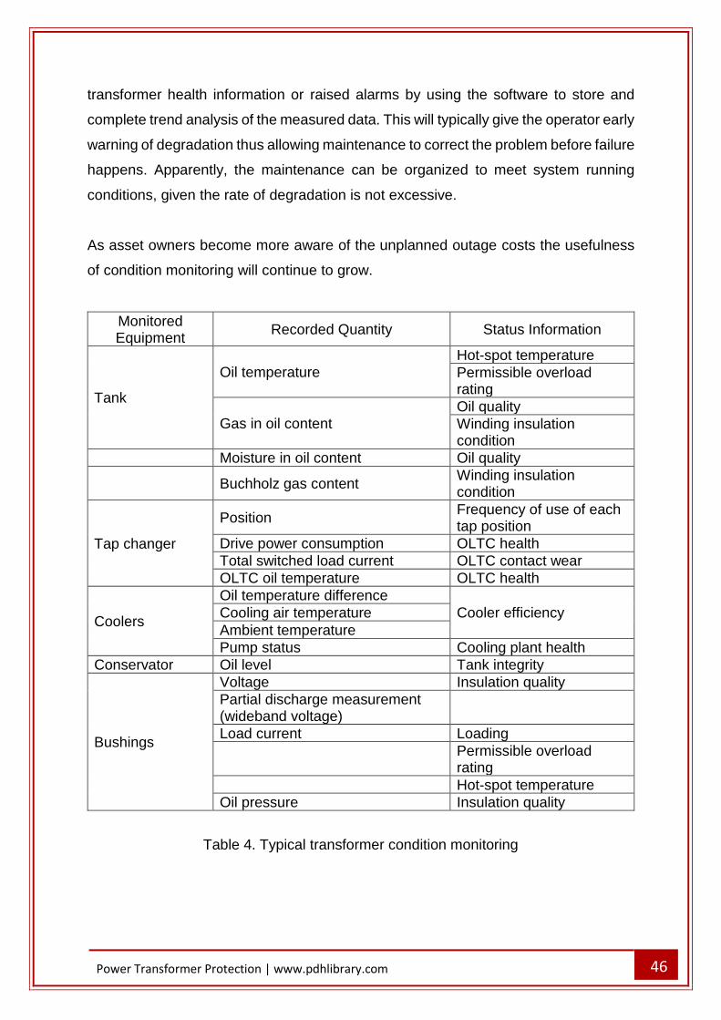
TRANSFORMER CONDITION MONITORING
It is practical to equip power transformers with measuring instruments to discover early
degradation signs of different components and give warning to the operator. This way
lengthy and expensive outage due to failure can be avoided. This strategy, which can
be used to other devices as well as transformers, is known as condition monitoring. It
is implemented with the goal to provide the operator with regular information on the
transformer condition. By reviewing the provided information trends, the operator can
make an educated judgment regarding maintenance frequency and detect early
deterioration signs. If ignored, these signs would lead to internal faults. Monitoring
techniques are an addition to, but are not a replacement for transformer protection.
The extent to which transformer condition monitoring is used depends on many
factors, amongst which are asset owner policy, the suitability of the design, the
importance of the asset to system service, and the general reliability record. Hence, it
should not be expected that all transformers are equipped with condition monitoring
instruments. A common condition monitoring system for an oil-immersed power
transformer is capable of monitoring the condition of different transformer components.
This is summarized in Table 4. There can be certain overlap with the measurements
available from a digital/numerical protection relay. The operator can be presented with
B
A
C
Voltage transformer
Ursd>
Residual voltage relay
46
Power Transformer Protection | www.pdhlibrary.com
transformer health information or raised alarms by using the software to store and
complete trend analysis of the measured data. This will typically give the operator early
warning of degradation thus allowing maintenance to correct the problem before failure
happens. Apparently, the maintenance can be organized to meet system running
conditions, given the rate of degradation is not excessive.
As asset owners become more aware of the unplanned outage costs the usefulness
of condition monitoring will continue to grow.
Monitored Equipment
Recorded Quantity Status Information
Tank
Oil temperature Hot-spot temperature
Permissible overload rating
Gas in oil content Oil quality
Winding insulation condition
Moisture in oil content Oil quality
Buchholz gas content Winding insulation condition
Tap changer
Position Frequency of use of each tap position
Drive power consumption OLTC health
Total switched load current OLTC contact wear
OLTC oil temperature OLTC health
Coolers
Oil temperature difference
Cooler efficiency Cooling air temperature
Ambient temperature
Pump status Cooling plant health
Conservator Oil level Tank integrity
Bushings
Voltage Insulation quality
Partial discharge measurement (wideband voltage)
Load current Loading
Permissible overload rating
Hot-spot temperature
Oil pressure Insulation quality
Table 4. Typical transformer condition monitoring
47
Power Transformer Protection | www.pdhlibrary.com
TRANSFORMER PROTECTION EXAMPLES
Next sections give examples of the modern relays used for transformer protection.
Alstom type KBCH protection relay is used to present the complexity of the required
calculations.
PROVISION OF VECTOR GROUP COMPENSATION AND ZERO-SEQUENCE
FILTERING
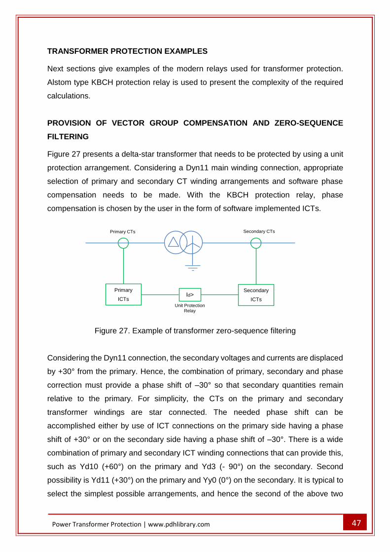
Figure 27 presents a delta-star transformer that needs to be protected by using a unit
protection arrangement. Considering a Dyn11 main winding connection, appropriate
selection of primary and secondary CT winding arrangements and software phase
compensation needs to be made. With the KBCH protection relay, phase
compensation is chosen by the user in the form of software implemented ICTs.
Figure 27. Example of transformer zero-sequence filtering
Considering the Dyn11 connection, the secondary voltages and currents are displaced
by +30° from the primary. Hence, the combination of primary, secondary and phase
correction must provide a phase shift of –30° so that secondary quantities remain
relative to the primary. For simplicity, the CTs on the primary and secondary
transformer windings are star connected. The needed phase shift can be
accomplished either by use of ICT connections on the primary side having a phase
shift of +30° or on the secondary side having a phase shift of –30°. There is a wide
combination of primary and secondary ICT winding connections that can provide this,
such as Yd10 (+60°) on the primary and Yd3 (- 90°) on the secondary. Second
possibility is Yd11 (+30°) on the primary and Yy0 (0°) on the secondary. It is typical to
select the simplest possible arrangements, and hence the second of the above two
Primary CTs Secondary CTs
Id> Secondary
ICTs
Primary
ICTs Unit Protection
Relay
48
Power Transformer Protection | www.pdhlibrary.com
possibilities could be selected. Nevertheless, the current distribution in the transformer
primary and secondary windings caused by an external earth fault on the transformer
secondary side must be considered. The transformer has an earth connection on the
secondary winding, so it can transfer zero sequence current to the fault. Application of
star connected main CTs and Yy0 connected ICTs gives a path for the zero sequence
current that can reach the protection relay. On the transformer primary side, the delta
connected main primary winding causes zero-sequence current to circulate round the
delta. Therefore they will not be detected by the primary side main CTs. Hence, the
protection relay will not detect any zero-sequence current on the transformer primary
side. Instead it detects the secondary side zero sequence current incorrectly as an in-
zone fault. The solution is to install the ICTs on the transformer secondary side with a
delta winding. That way the zero-sequence current would circulate round the delta and
would not be detected by the relay. Hence, a general rule can be adopted. It states
that the transformer winding with a connection to earth must have a delta-connected
main or ICT for unit protection to function correctly. Yy0 connection selection for the
primary side ICTs and Yd1 (–30°) for the secondary side ICTs gives the required
phase shift and the zero-sequence trap on the secondary side. Modern numerical
protection relays use a setting wizard that requires entering only vector group and zero
sequence data. The protection relay then automatically adjusts itself to suit the
application.
DELTA-STAR TRANSFORMER UNIT PROTECTION
Figure 28 presents a delta-star transformer to which unit protection needs to be
applied. Restricted earth fault protection to the star winding also needs to be used.
Referring to the figure, the ICTs have already been correctly chosen, and are
conveniently set in software. Hence, it remains to compute adequate compensation
ratio (it is assumed that the transformer does not have taps), transformer differential
protection settings and restricted earth fault settings.
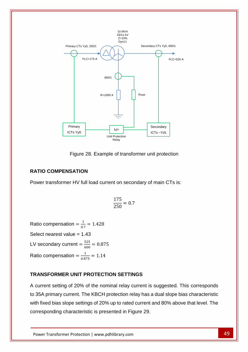
49
Power Transformer Protection | www.pdhlibrary.com
Figure 28. Example of transformer unit protection
RATIO COMPENSATION
Power transformer HV full load current on secondary of main CTs is:
175
250= 0.7
Ratio compensation =1
0.7= 1.428
Select nearest value = 1.43
LV secondary current =525
600= 0.875
Ratio compensation =1
0.875= 1.14
TRANSFORMER UNIT PROTECTION SETTINGS
A current setting of 20% of the nominal relay current is suggested. This corresponds
to 35A primary current. The KBCH protection relay has a dual slope bias characteristic
with fixed bias slope settings of 20% up to rated current and 80% above that level. The
corresponding characteristic is presented in Figure 29.
600/1
Rstab
Primary CTs Yy0, 250/1 Secondary CTs Yy0, 600/1
Id> Secondary
ICTs –Yd1
Primary
ICTs Yy0 Unit Protection
Relay
R=1000 A
10 MVA 33/11 kV Z=10% Dyn11
FLC=525 A FLC=175 A
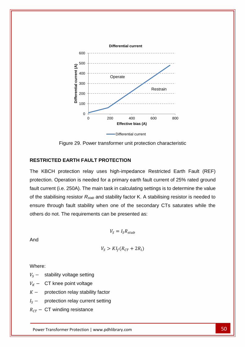
50
Power Transformer Protection | www.pdhlibrary.com
Figure 29. Power transformer unit protection characteristic
RESTRICTED EARTH FAULT PROTECTION
The KBCH protection relay uses high-impedance Restricted Earth Fault (REF)
protection. Operation is needed for a primary earth fault current of 25% rated ground
fault current (i.e. 250A). The main task in calculating settings is to determine the value
of the stabilising resistor Rstab and stability factor K. A stabilising resistor is needed to
ensure through fault stability when one of the secondary CTs saturates while the
others do not. The requirements can be presented as:
𝑉𝑆 = 𝐼𝑆𝑅𝑠𝑡𝑎𝑏
And
𝑉𝑆 > 𝐾𝐼𝑓(𝑅𝐶𝑇 + 2𝑅𝑙)
Where:
𝑉𝑆 − stability voltage setting
𝑉𝐾 − CT knee point voltage
𝐾 − protection relay stability factor
𝐼𝑆 − protection relay current setting
𝑅𝐶𝑇 − CT winding resistance
0
100
200
300
400
500
600
0 200 400 600 800
Dif
fere
nti
al c
urr
en
t (A
)
Effective bias (A)
Differential current
Differential current
Restrain
Operate
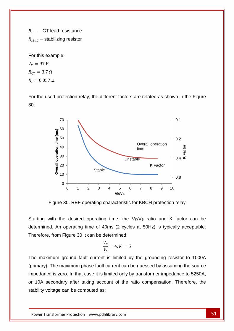
51
Power Transformer Protection | www.pdhlibrary.com
𝑅𝑙 − CT lead resistance
𝑅𝑠𝑡𝑎𝑏 − stabilizing resistor
For this example:
𝑉𝐾 = 97 𝑉
𝑅𝐶𝑇 = 3.7 Ω
𝑅𝑙 = 0.057 Ω
For the used protection relay, the different factors are related as shown in the Figure
30.
Figure 30. REF operating characteristic for KBCH protection relay
Starting with the desired operating time, the VK/VS ratio and K factor can be
determined. An operating time of 40ms (2 cycles at 50Hz) is typically acceptable.
Therefore, from Figure 30 it can be determined:
𝑉𝐾
𝑉𝑆= 4, 𝐾 = 5
The maximum ground fault current is limited by the grounding resistor to 1000A
(primary). The maximum phase fault current can be guessed by assuming the source
impedance is zero. In that case it is limited only by transformer impedance to 5250A,
or 10A secondary after taking account of the ratio compensation. Therefore, the
stability voltage can be computed as:
0.1
0.2
0.4
0.8
0
10
20
30
40
50
60
70
0 1 2 3 4 5 6 7 8 9 10K
Fa
cto
r
Ove
rall
op
era
tio
n t
ime
(m
s)
Vk/Vs
Unstable
Stable K Factor
Overall operation time

52
Power Transformer Protection | www.pdhlibrary.com
𝑉𝑆 = 0.5 × 10(3.7 + 2 × 0.057) = 19.07 𝑉
Therefore,
Calculated VK =4x19.07= 76.28 V
However,
Actual VK = 91V and VK/VS = 4.77
Therefore, with K = 0.5, the protection is unstable as can be seen in Figure 30.
By applying an iterative process for VK/VS and K, a final acceptable result of VK/VS =
4.55, K=0.6 is reached. This results in a tripping time faster than 40ms.
The needed ground fault setting current IOP is 250A. The selected E/F CT has an
exciting current Ie of 1%. Therefore, using the formula:
𝐼𝑂𝑃 = 𝐶𝑇𝑟𝑎𝑡𝑖𝑜 × (𝐼𝑆 + 𝑛𝐼𝑒)
where:
n = no of CTs in parallel (=4)
IS = 0.377, use 0.38 nearest settable value.
The stabilising resistance Rstab can be calculated as 60.21Ω.
The protection relay can only withstand a maximum of 3kV peak under fault conditions.
A check is needed to understand if this voltage is surpassed – if it is, a non-linear
resistor, must be connected across the protection relay and stabilising resistor. The
peak voltage is calculated using the equation:
𝑉𝑃 = 2√2𝑉𝐾(𝑉𝑓 − 𝑉𝐾)
Where:
𝑉𝑓 = 𝐼𝑓(𝑅𝐶𝑇 + 2𝑅𝑙 + 𝑅𝑠𝑡𝑎𝑏)
And
53
Power Transformer Protection | www.pdhlibrary.com
𝐼𝑓= fault current in secondary of CT circuit. Substituting values gives 𝑉𝑃 = 544 𝑉. Thus
a non-linear resistor is not needed.
ON-LOAD TAP CHANGING TRANSFORMER UNIT PROTECTION
The previous example considers a transformer without the taps. In reality, majority of
transformers have a range of taps to cater for different loading situations. While
majority of transformers have an off-load tap-changer, power transformers used for
network voltage control are equipped with an on-load tap-changer. The protection
settings must consider tap-change variation to avoid the chance of spurious trips at
extreme tap positions. For this example, the same transformer as in previous section
will be used, but with an on-load tapping range of +5% to -15%. The tap-changer is
installed on the primary winding, while the tap-step typically does not matter.
RATIO CORRECTION
The mid-tap position is used to compute the ratio correction factors. The mid tap
position is –5%. At this tap position:
Primary voltage to give rated secondary voltage: = 33 x 0.95 = 31.35kV
Rated Primary Current = 184A
Transformer HV full load current on secondary of main CTs is:
184
250= 0.737
Ratio compensation = 1
0.737= 1.36
LV secondary current = 525
600= 0.875
Ratio compensation = 1
0.875= 1.14
Both of the above values can be set in the protection relay.
BIAS SLOPE SETTING
The on-load tapping range of +5% to -15% provides rise to a maximum excursion of -
10% from the -5% mid-tap position. Since the differential protection scheme notionally
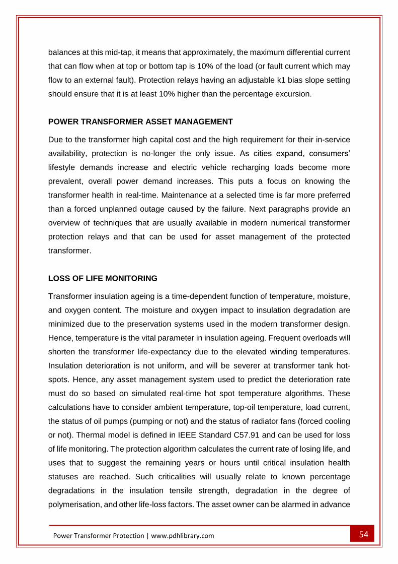
54
Power Transformer Protection | www.pdhlibrary.com
balances at this mid-tap, it means that approximately, the maximum differential current
that can flow when at top or bottom tap is 10% of the load (or fault current which may
flow to an external fault). Protection relays having an adjustable k1 bias slope setting
should ensure that it is at least 10% higher than the percentage excursion.
POWER TRANSFORMER ASSET MANAGEMENT
Due to the transformer high capital cost and the high requirement for their in-service
availability, protection is no-longer the only issue. As cities expand, consumers’
lifestyle demands increase and electric vehicle recharging loads become more
prevalent, overall power demand increases. This puts a focus on knowing the
transformer health in real-time. Maintenance at a selected time is far more preferred
than a forced unplanned outage caused by the failure. Next paragraphs provide an
overview of techniques that are usually available in modern numerical transformer
protection relays and that can be used for asset management of the protected
transformer.
LOSS OF LIFE MONITORING
Transformer insulation ageing is a time-dependent function of temperature, moisture,
and oxygen content. The moisture and oxygen impact to insulation degradation are
minimized due to the preservation systems used in the modern transformer design.
Hence, temperature is the vital parameter in insulation ageing. Frequent overloads will
shorten the transformer life-expectancy due to the elevated winding temperatures.
Insulation deterioration is not uniform, and will be severer at transformer tank hot-
spots. Hence, any asset management system used to predict the deterioration rate
must do so based on simulated real-time hot spot temperature algorithms. These
calculations have to consider ambient temperature, top-oil temperature, load current,
the status of oil pumps (pumping or not) and the status of radiator fans (forced cooling
or not). Thermal model is defined in IEEE Standard C57.91 and can be used for loss
of life monitoring. The protection algorithm calculates the current rate of losing life, and
uses that to suggest the remaining years or hours until critical insulation health
statuses are reached. Such criticalities will usually relate to known percentage
degradations in the insulation tensile strength, degradation in the degree of
polymerisation, and other life-loss factors. The asset owner can be alarmed in advance
55
Power Transformer Protection | www.pdhlibrary.com
that an outage will be needed for reconditioning or rewinding. That way investment
budgeting can be made years and months ahead of time.
TRANSFORMER THROUGH-FAULT MONITORING
Loss of life monitoring is used to track the deterioration caused by long term, repeated
overloading. Nevertheless, it is not the right method to monitor short-term heavy fault
currents which flow through the transformer. Through faults are a major cause of
transformer failure and damage, as they stress the insulation and mechanical integrity.
A special through-fault monitor is needed to monitor currents introduced by external
faults that pass through the transformer. These currents may range from 3.5 times up
to tens of times of the transformer rated current. Many relays perform an I2t calculation
when the through current exceeds a user-set threshold. That way the heating effect of
the square of the maximum phase current, and the fault duration are calculated.
Calculation results are added to monitored cumulative values so that utilities can
organize transformer maintenance or specify required system reinforcement.
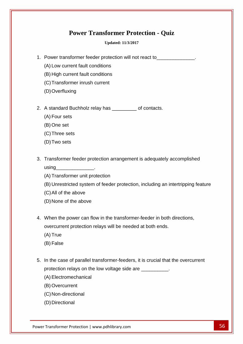
56
Power Transformer Protection | www.pdhlibrary.com
Power Transformer Protection - Quiz
Updated: 11/3/2017
1. Power transformer feeder protection will not react to______________.
(A) Low current fault conditions
(B) High current fault conditions
(C) Transformer inrush current
(D) Overfluxing
2. A standard Buchholz relay has _________ of contacts.
(A) Four sets
(B) One set
(C) Three sets
(D) Two sets
3. Transformer feeder protection arrangement is adequately accomplished
using______________.
(A) Transformer unit protection
(B) Unrestricted system of feeder protection, including an intertripping feature
(C) All of the above
(D) None of the above
4. When the power can flow in the transformer-feeder in both directions,
overcurrent protection relays will be needed at both ends.
(A) True
(B) False
5. In the case of parallel transformer-feeders, it is crucial that the overcurrent
protection relays on the low voltage side are __________.
(A) Electromechanical
(B) Overcurrent
(C) Non-directional
(D) Directional
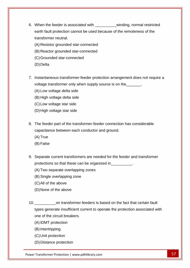
57
Power Transformer Protection | www.pdhlibrary.com
6. When the feeder is associated with __________winding, normal restricted
earth fault protection cannot be used because of the remoteness of the
transformer neutral.
(A) Resistor grounded star-connected
(B) Reactor grounded star-connected
(C) Grounded star-connected
(D) Delta
7. Instantaneous transformer-feeder protection arrangement does not require a
voltage transformer only when supply source is on the_______.
(A) Low voltage delta side
(B) High voltage delta side
(C) Low voltage star side
(D) High voltage star side
8. The feeder part of the transformer-feeder connection has considerable
capacitance between each conductor and ground.
(A) True
(B) False
9. Separate current transformers are needed for the feeder and transformer
protections so that these can be organized in__________.
(A) Two separate overlapping zones
(B) Single overlapping zone
(C) All of the above
(D) None of the above
10. __________on transformer-feeders is based on the fact that certain fault
types generate insufficient current to operate the protection associated with
one of the circuit breakers.
(A) IDMT protection
(B) Intertripping
(C) Unit protection
(D) Distance protection
58
Power Transformer Protection | www.pdhlibrary.com
11. An alternative to intertripping is to detect fault condition by
measuring_________.
(A) Feeder residual voltage
(B) Neutral residual voltage
(C) All of the above
(D) None of the above
12. Ground faults in the system may result in displacement of the transformer
neutral. Therefore, discrimination is accomplished using ____________.
(A) Definite time
(B) Inverse time
(C) All of the above
(D) None of the above
13. A current setting of _________ of the nominal relay current is suggested for
transformer unit protection.
(A) 20%
(B) 10%
(C) 15%
(D) 25%
14. A stabilising resistor is needed to ensure _________when one of the
secondary CTs saturates while the others do not.
(A) Through fault stability
(B) Inrush current stability
(C) All of the above
(D) None of the above
15. A transformer winding fault is limited in magnitude by___________.
(A) Winding connection arrangement
(B) Neutral grounding impedance
(C) All of the above
(D) None of the above
59
Power Transformer Protection | www.pdhlibrary.com
16. In the case transformer is grounded through impedance, for a fault on a
transformer secondary winding, the matching primary current will depend on
the ______________.
(A) Transformation ratio between the primary winding and the short-circuited
secondary turns
(B) Transformation ratio between the primary winding and the open-circuited
secondary turns
(C) Winding connection arrangement
(D) Neutral grounding impedance
17. Transformer tank protection is also known as__________.
(A) Buchholz protection
(B) Howard protection
(C) All of the above
(D) None of the above
18. A line surge can cause part-winding resonance, involving voltages up to
_______times of the nominal voltage.
(A) 5
(B) 15
(C) 10
(D) 20
19. Transformer overheating may happen due to ___________.
(A) Sustained overload
(B) Failure of the forced cooling mechanism
(C) All of the above
(D) None of the above

60
Power Transformer Protection | www.pdhlibrary.com
20. Maximum mechanical stress on transformer windings happens during the
_____________of the fault.
(A) Second cycle
(B) First cycle
(C) First two cycles
(D) First three cycles
21. Transformer overvoltages can be grouped in ____________.
(A) Transient surge voltages
(B) Power frequency overvoltages
(C) All of the above
(D) None of the above
22. Temperature of around ___________is conceived as the transformer normal
maximum working value.
(A) 90°C
(B) 100°C
(C) 85°C
(D) 95°C
23. High Rupturing Capacity (HRC) fuses, even though very fast in operation with
huge fault currents, are super slow with currents of less than _________their
nominal value.
(A) Three times
(B) Two times
(C) Four times
(D) Two times
24. Restricted earth fault protection is a unit protection arrangement for one
winding of the transformer.
(A) True
(B) False
61
Power Transformer Protection | www.pdhlibrary.com
25. Demands for phase and ratio correction can be met by ______________.
(A) External interposing current transformers (ICTs)
(B) Delta connection of the main CTs
(C) All of the above
(D) None of the above
26. When the power transformer has only one of its three windings connected to a
source of supply, with the other two windings supplying loads, a protection
relay with __________ can be applied.
(A) Two CT inputs
(B) Three sets of CT inputs
(C) Three CT inputs
(D) Two sets of CT inputs
27. The only significant disadvantage of the Combined Differential/REF
arrangement is that the REF element is likely to trip for heavy internal faults
along with the differential elements.
(A) True
(B) False
28. Transformer overfluxing primarily happens due to____________.
(A) Low system frequency
(B) High system voltage
(C) All of the above
(D) None of the above
29. Geomagnetic disturbances may cause _________ without the V/f threshold
being surpassed.
(A) Overfluxing
(B) Excessive heating
(C) Increased inrush currents
(D) Increased harmonics

62
Power Transformer Protection | www.pdhlibrary.com
30. Restricted earth fault protection is not stable for all faults outside protection
zone.
(A) True
(B) False


![Winding temperature prediction in split-winding traction transformer · manufactured as seen in the Figure 1 [1] and is usually called a split-winding transformer. The transformer](https://img.pdfslide.net/doc/110x75/60b5dfb61a68b1378b3649a5/winding-temperature-prediction-in-split-winding-traction-transformer-manufactured.jpg)