Embed Size (px)
Citation preview
Power Transformers Basics
Transformer Basic Objective
• Introduce Basic Transformer Theory as it
Relates to Diagnostics
• Provide a Better Understanding of the
Diagnostic Test Environment
• Identify Important Information that should be
collected in the Diagnostic Test Process
Topics of Discussion
• Definition
• Transformer Types and Classifications
• Transformer Configurations
• Vector Groups
• Life Expectance
• Oil Preservation Systems
• Insulating Materials and Fluids
• Construction Forms
• Core Steel
• Nameplates
• Ratings
• Cooling Schemes
• Tap Changers (OLTC, DETC)
Transformer Categories
• Insulation System- Liquid Immersed- Dry Type- Gas Filled
• Construction- Tank Type- Core Type / Shell Type- 1 Phase / 3 Phase- Double-Wound, Multi-Winding, Auto
- Winding Configuration and Type
• Application
Transformer Types and Classifications
• Distribution
• Power
• Rectifier
• Arc-Furnace
• Network
• Regulating (Voltage Regulators)
• Phase Shifting
• Reactors*
Transformer Classifications
• Distribution• Rated 500 kVA and Below• Up to 34.5 kV• Step-down Application• Used in Customer Circuit
• Power• Rated 500 kVA and Above• Between Generation and Distribution• GSU Generator Step-Up, Autos, Transmission
Class XFMRs• Autotransformers
Winding Configurations
• Delta
• Wye
• Auto
• Zig-Zag
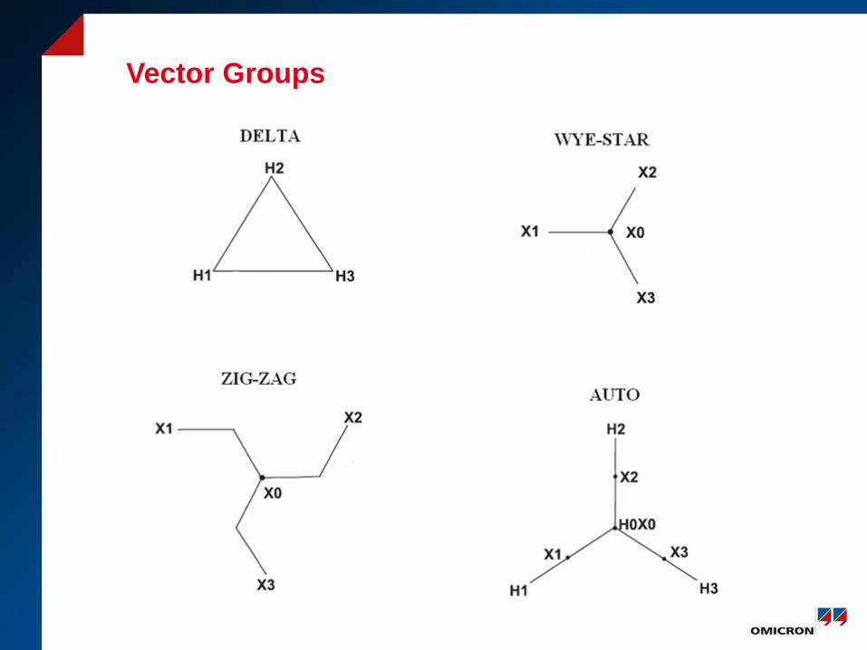
Vector Groups
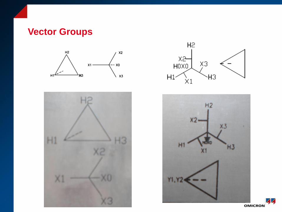
Vector Groups
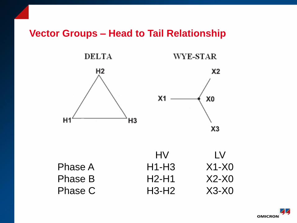
Vector Groups – Head to Tail Relationship
HV LV
Phase A H1-H3 X1-X0
Phase B H2-H1 X2-X0
Phase C H3-H2 X3-X0
Life Expectancy of Transformer Insulation
• 180,000 hrs or 20.55 years
• 110 C Hottest Spot for 65 C Temp Rise insulation
• Degree of Polymerization (200 -1200 DP)
• 1200 DP - New Paper
• 200 DP at 150,000 hrs (end of life)
Heat
Moisture
Oxygen
Insulating Materials and Fluids
• Oil• Mineral• Silicone• Askeral – Polychlorinated Biphenyls (PCB)• Natural and Synthetic Esters • High Molecular Weight Hydrocarbons• Synthetic
• Paper (cellulose)• wood fiber• manila rope
• Pressboard (wood fiber and cotton)
• Resin
• Varnish
Oil
• Most insulating fluids have very good properties,
however the unique characteristics and attributes of each
product must be considered when selecting an insulating
fluid for a specific application.
• Purpose
a. Dielectric Withstand
b. Heat Exchange (Cooling)
c. Arc Mitigation
Winding Types
1. Disk Winding
2. Pancake Winding
3. Helical Winding
4. Cylindrical or Layer Winding
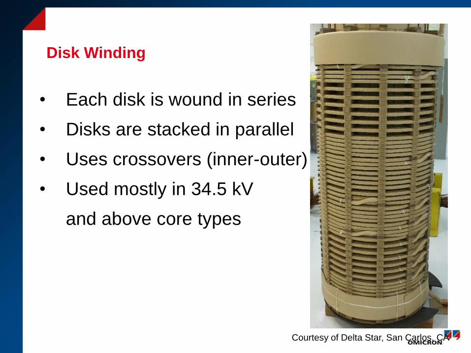
Disk Winding
• Each disk is wound in series
• Disks are stacked in parallel
• Uses crossovers (inner-outer)
• Used mostly in 34.5 kV
and above core types
Courtesy of Delta Star, San Carlos, CA
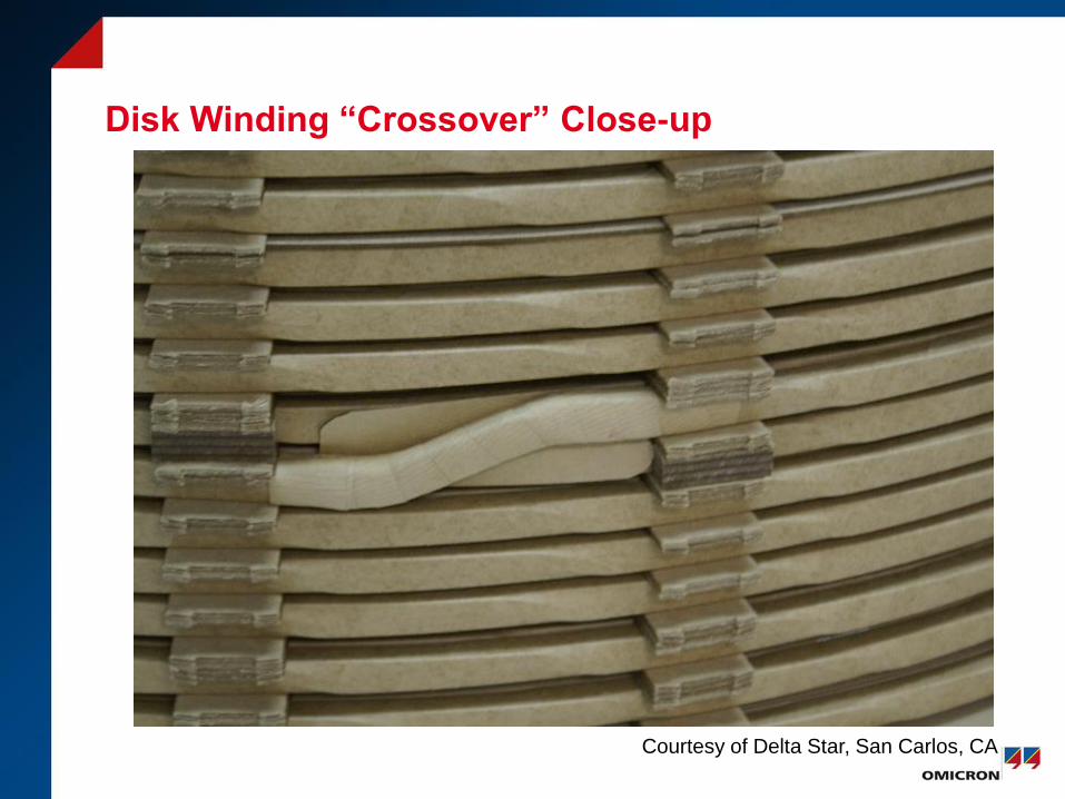
Disk Winding “Crossover” Close-up
Courtesy of Delta Star, San Carlos, CA
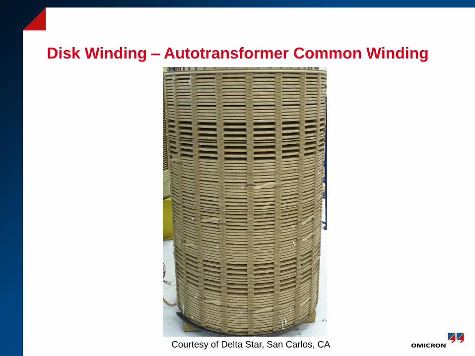
Disk Winding – Autotransformer Common Winding
Courtesy of Delta Star, San Carlos, CA
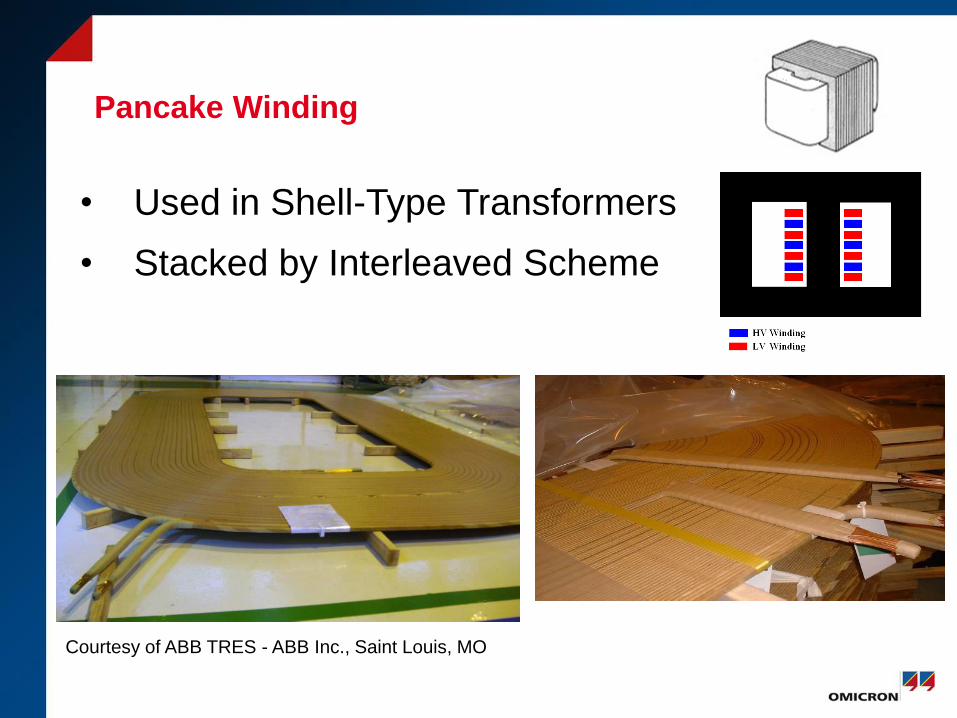
Pancake Winding
• Used in Shell-Type Transformers
• Stacked by Interleaved Scheme
Courtesy of ABB TRES - ABB Inc., Saint Louis, MO
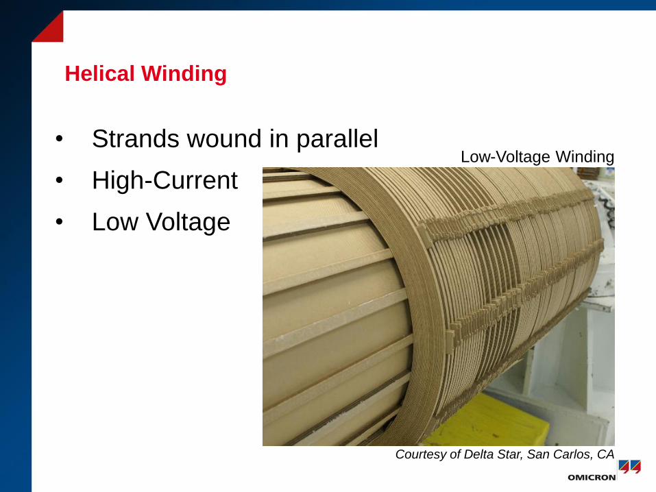
Helical Winding
• Strands wound in parallel
• High-Current
• Low Voltage
Courtesy of Delta Star, San Carlos, CA
Low-Voltage Winding
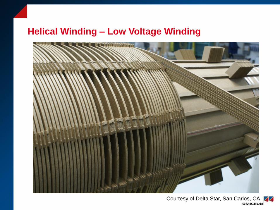
Helical Winding – Low Voltage Winding
Courtesy of Delta Star, San Carlos, CA

Layer or Barrel Winding
• Conductors wound side by side
• Layers can be wound
on top each other
• Regulating Windings
• Tertiary Windings
Regulating Winding
Courtesy of Delta Star, San Carlos, CA
Oil Preservation Systems
• Free Breathing Conservator
• Sealed - Air/Gas Headspace
• Pressurized Nitrogen
• Conservator with Bladder
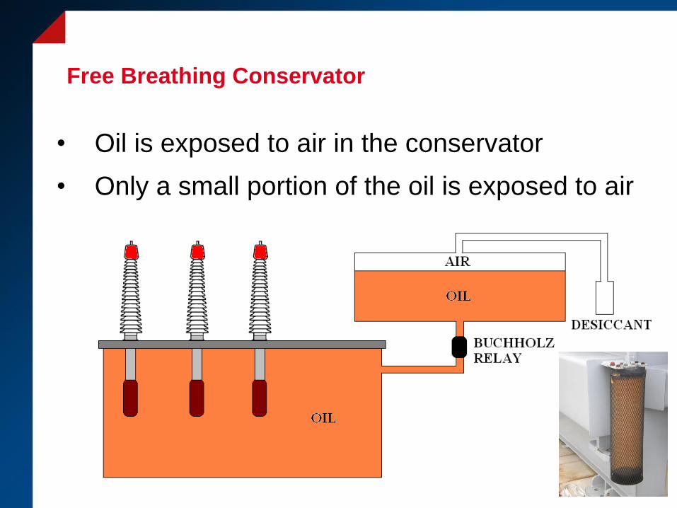
Free Breathing Conservator
• Oil is exposed to air in the conservator
• Only a small portion of the oil is exposed to air
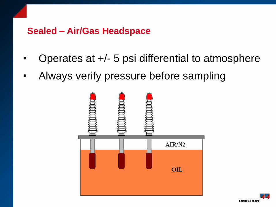
Sealed – Air/Gas Headspace
• Operates at +/- 5 psi differential to atmosphere
• Always verify pressure before sampling
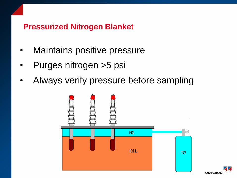
Pressurized Nitrogen Blanket
• Maintains positive pressure
• Purges nitrogen >5 psi
• Always verify pressure before sampling
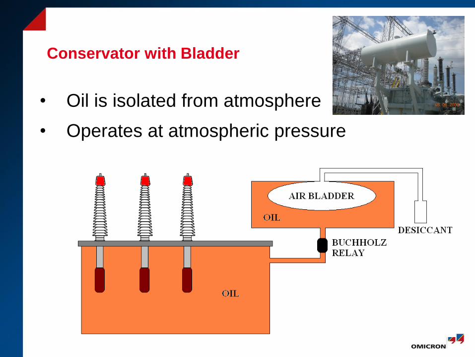
Conservator with Bladder
• Oil is isolated from atmosphere
• Operates at atmospheric pressure
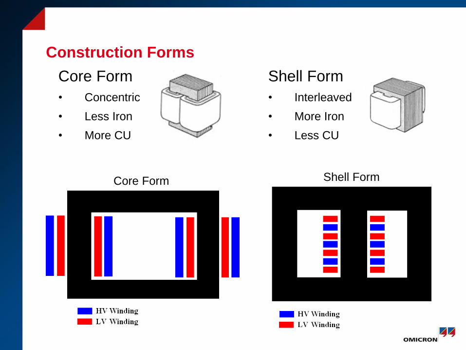
Construction Forms
Core Form
• Concentric
• Less Iron
• More CU
Shell Form
• Interleaved
• More Iron
• Less CU
Core Form Shell Form
Core Steel
• Goal – Minimize cost of ownership by minimizing losses
• Constructed from steel sheets (0.25 mm) that has a
coating (insulation); stacked laminations
• Eddy Losses – Proportional to the sheet thickness
• Hysteresis Losses – Influenced by the metallurgical
recipe and process
• Grain Oriented – Align magnetic domains for the best
performance in plane of intended flux paths.
Core Steel
• Cold Rolled Grain Oriented (CGO)
• High Flux Density Grain Oriented (HGO) Hi-B
• Laser Etched
• Plasma Irradiated
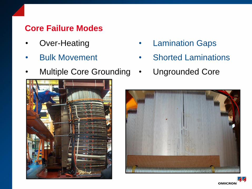
Core Failure Modes
• Over-Heating
• Bulk Movement
• Multiple Core Grounding
• Lamination Gaps
• Shorted Laminations
• Ungrounded Core
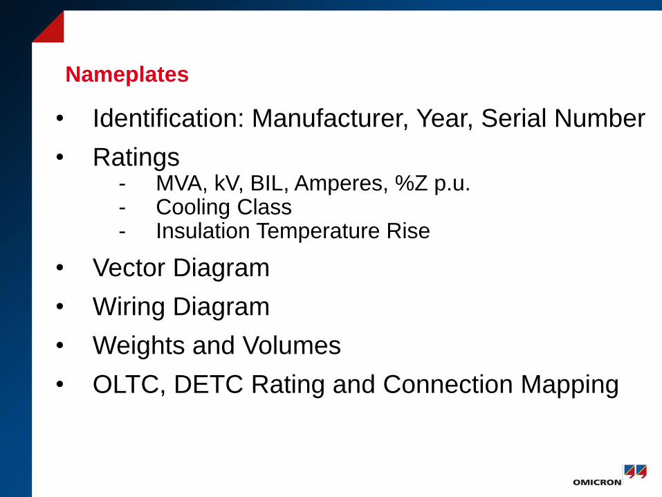
Nameplates
• Identification: Manufacturer, Year, Serial Number
• Ratings - MVA, kV, BIL, Amperes, %Z p.u.- Cooling Class- Insulation Temperature Rise
• Vector Diagram
• Wiring Diagram
• Weights and Volumes
• OLTC, DETC Rating and Connection Mapping
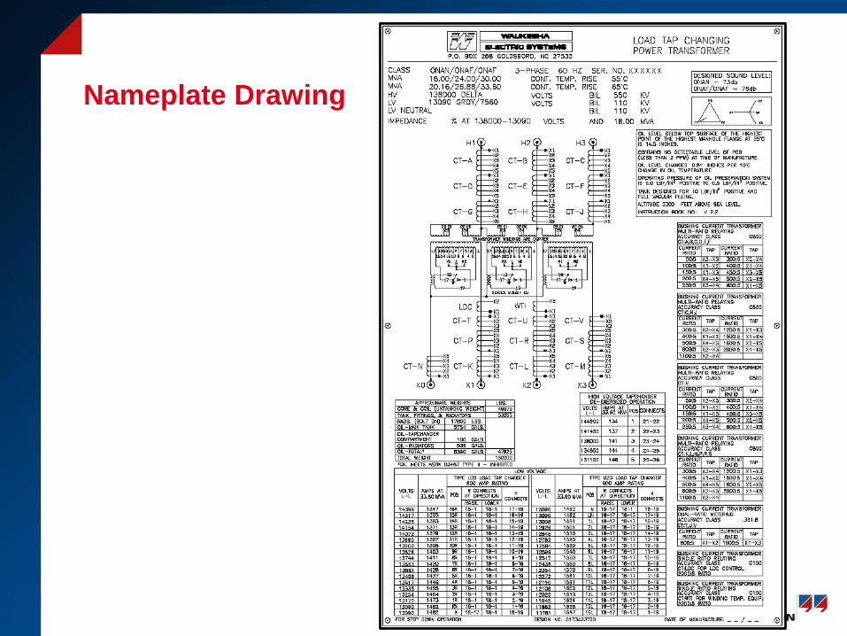
Nameplate Drawing
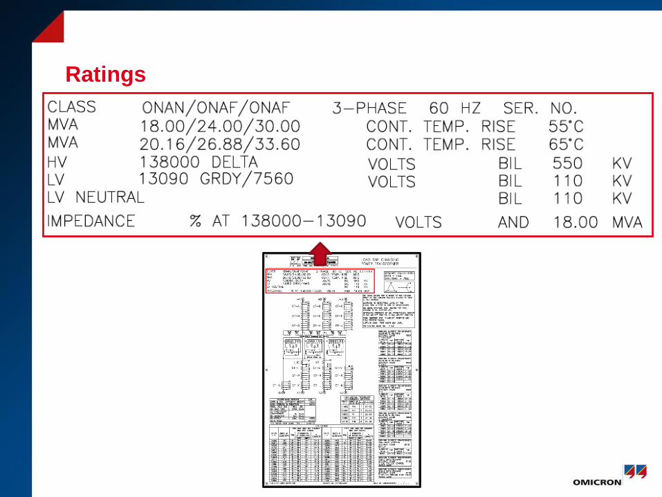
Ratings
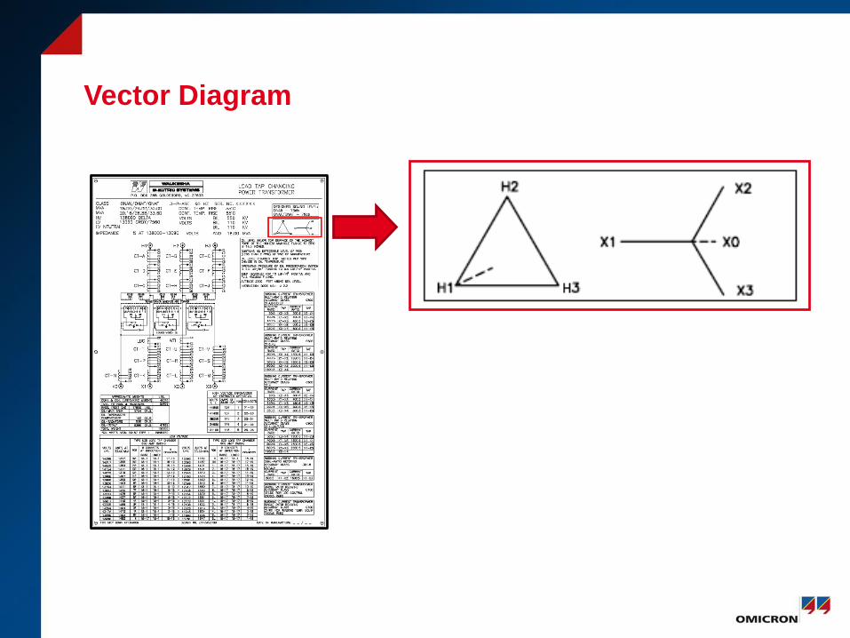
Vector Diagram
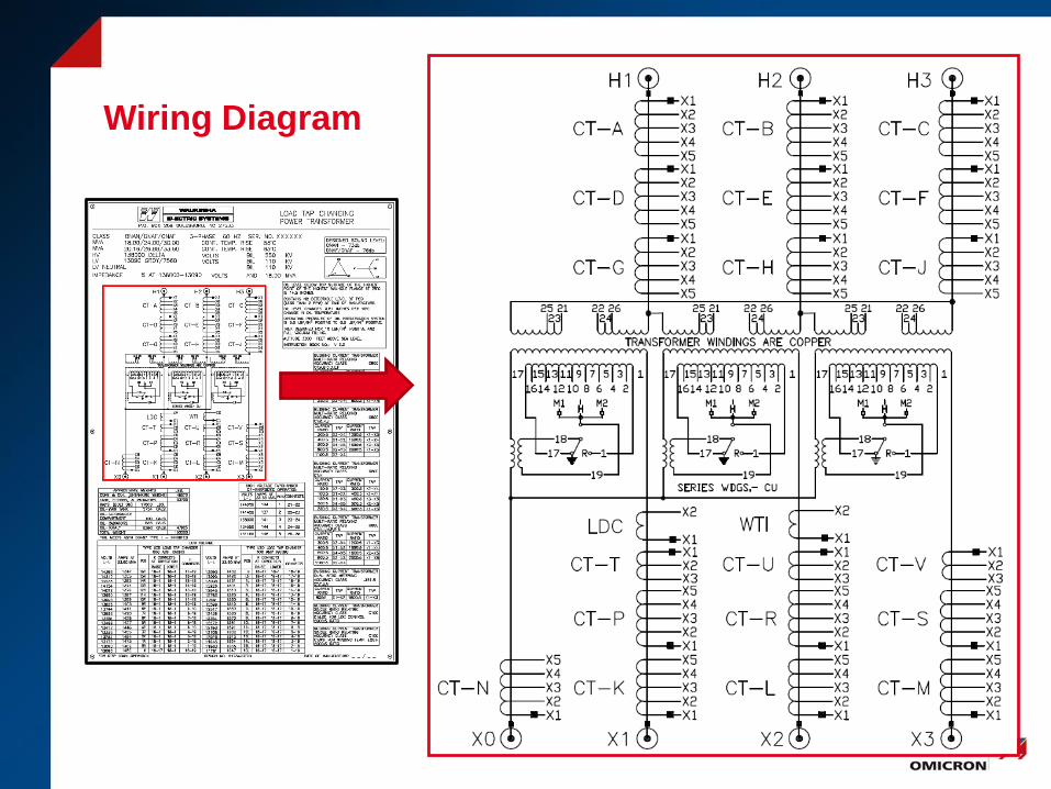
Wiring Diagram
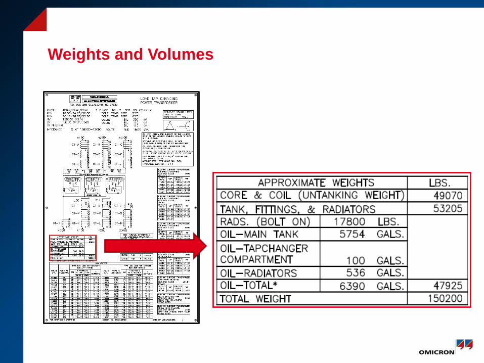
Weights and Volumes
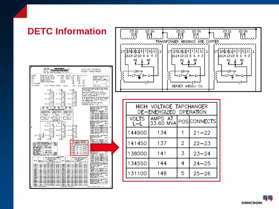
DETC Information
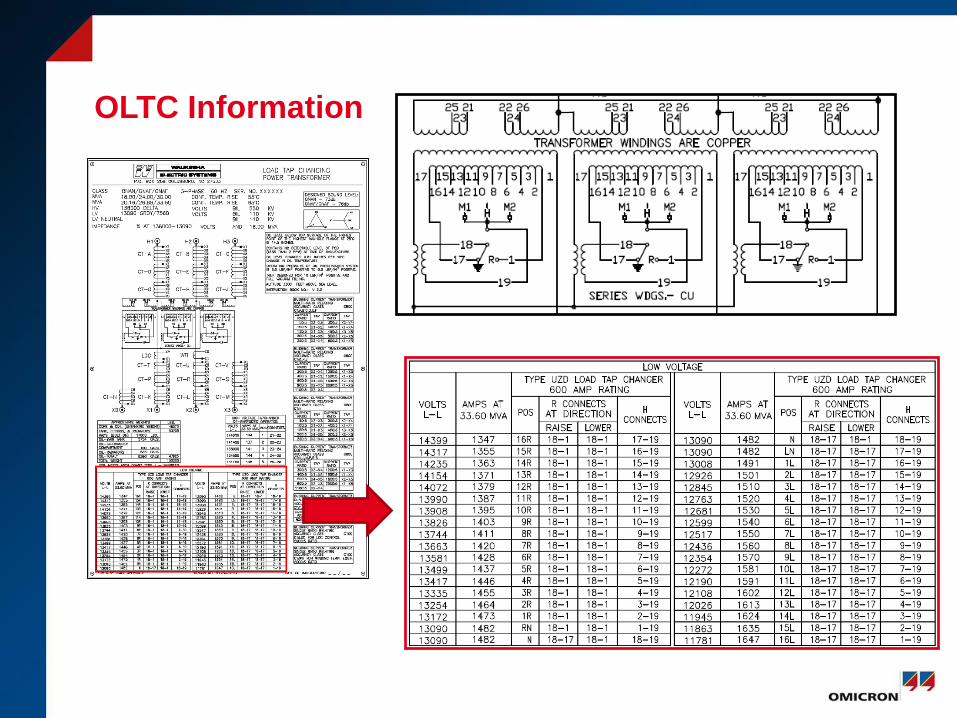
OLTC Information
Fault Protection
1. Pressure Relief Valves
2. Sudden Pressure Relay
3. Buchholtz Relay
• Sudden Pressure Relay
• Gas Accumulation Relay
• Only Applied to Conservator Systems
Cooling
• Prevent damage and loss of life to the insulation system
• Ages paper, pressboard, and oil
• Natural Convection
• Fans
• Pumps
• Water
• Directed Flow
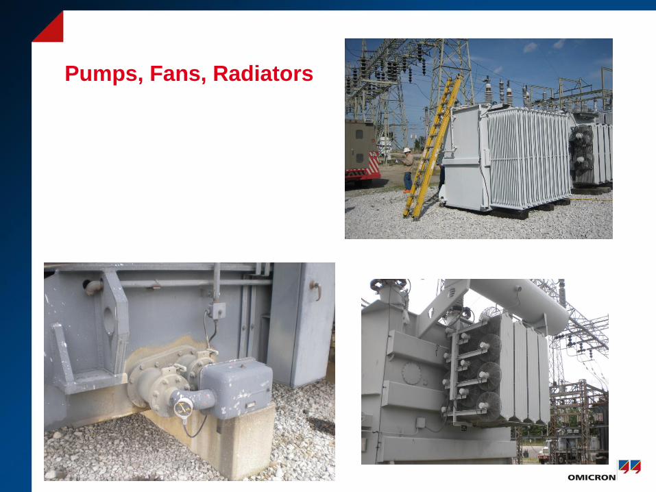
Pumps, Fans, Radiators
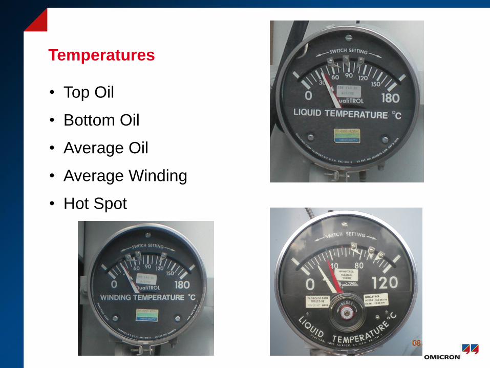
Temperatures
• Top Oil
• Bottom Oil
• Average Oil
• Average Winding
• Hot Spot
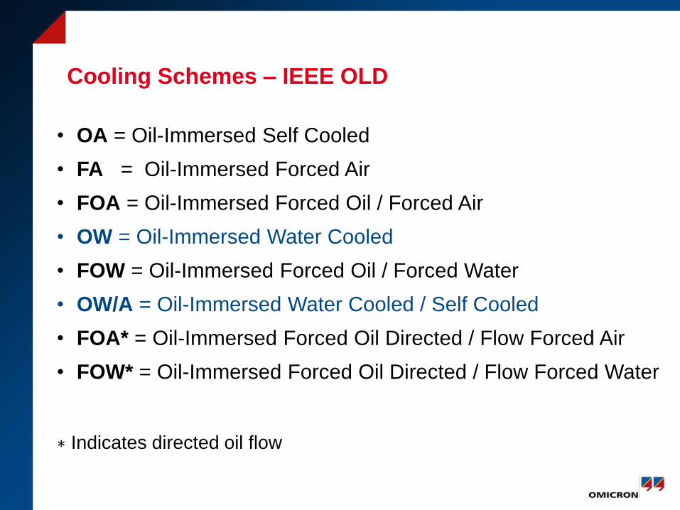
Cooling Schemes – IEEE OLD
• OA = Oil-Immersed Self Cooled
• FA = Oil-Immersed Forced Air
• FOA = Oil-Immersed Forced Oil / Forced Air
• OW = Oil-Immersed Water Cooled
• FOW = Oil-Immersed Forced Oil / Forced Water
• OW/A = Oil-Immersed Water Cooled / Self Cooled
• FOA* = Oil-Immersed Forced Oil Directed / Flow Forced Air
• FOW* = Oil-Immersed Forced Oil Directed / Flow Forced Water
∗ Indicates directed oil flow
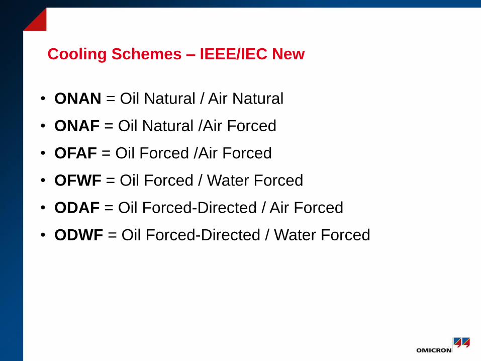
Cooling Schemes – IEEE/IEC New
• ONAN = Oil Natural / Air Natural
• ONAF = Oil Natural /Air Forced
• OFAF = Oil Forced /Air Forced
• OFWF = Oil Forced / Water Forced
• ODAF = Oil Forced-Directed / Air Forced
• ODWF = Oil Forced-Directed / Water Forced
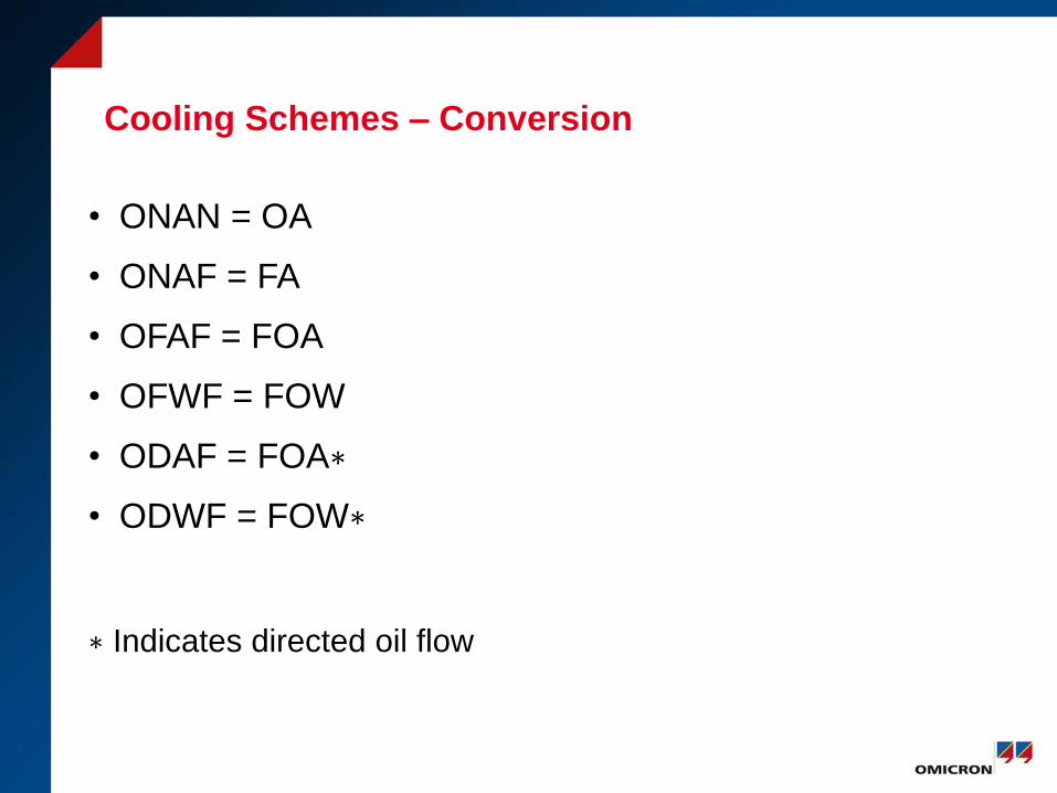
Cooling Schemes – Conversion
• ONAN = OA
• ONAF = FA
• OFAF = FOA
• OFWF = FOW
• ODAF = FOA∗
• ODWF = FOW∗
∗ Indicates directed oil flow
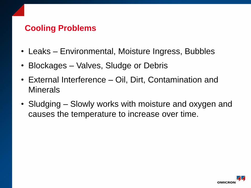
Cooling Problems
• Leaks – Environmental, Moisture Ingress, Bubbles
• Blockages – Valves, Sludge or Debris
• External Interference – Oil, Dirt, Contamination and
Minerals
• Sludging – Slowly works with moisture and oxygen and
causes the temperature to increase over time.
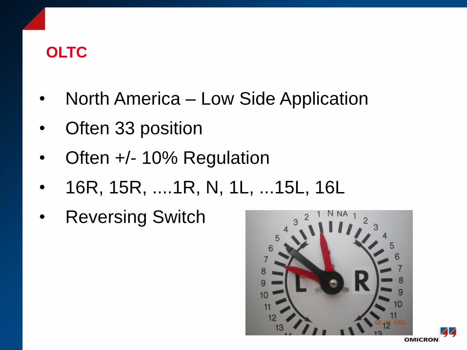
OLTC
• North America – Low Side Application
• Often 33 position
• Often +/- 10% Regulation
• 16R, 15R, ....1R, N, 1L, ...15L, 16L
• Reversing Switch
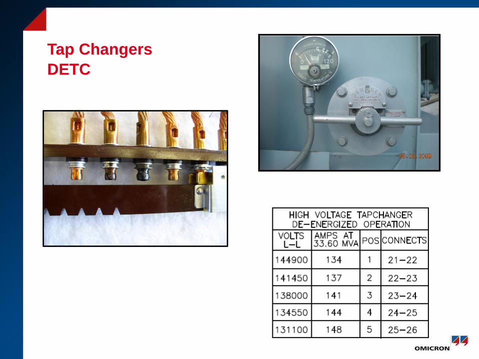
Tap Changers
DETC
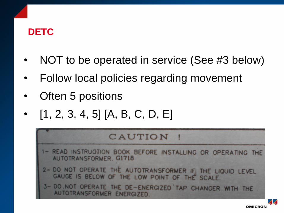
DETC
• NOT to be operated in service (See #3 below)
• Follow local policies regarding movement
• Often 5 positions
• [1, 2, 3, 4, 5] [A, B, C, D, E]
Active LTC Diagnostics
• Exciting Currents
• Turns Ratio
• DC Winding Resistance, Slope, Ripple
• DGA
• IR
• Acoustics
© OMICRON
Thank You for Your Attention