Embed Size (px)
Citation preview
Technical Marketing Sheet
©National Oilwell Varco - All rights reserved - RigDoc 95894250 Rev.2
PowerBlade™ - Kinetic Energy Recovery SystemNOV PowerBlade is an innovative technology suitable for drilling and hoisting systems. It preserves energy to reduce fuel costs and lower emissions while increasing operational safety and reliability.
During operation, the PowerBlade system captures regenerated electrical energy when the drawworks, crane or winch slows and stops the load on the hook. Previously, this energy was dissipated as heat using braking resistors.
The PowerBlade stores this as kinetic energy using a flywheel that accelerates and gathers speed, capturing energy from vessel rising and block lowering during active heave compensation. This energy is then recycled and utilized to put power back onto the power grid when needed. The spinning flywheel rotates between 1,000 and 2,000 RPMs, charging and discharging energy in a safe fashion.
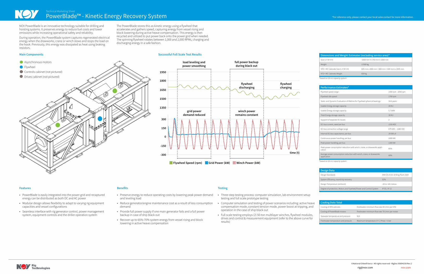
Main Components
Asynchronous motors
Flywheel
Controls cabinet (not pictured)
Drives cabinet (not pictured)
Features
• PowerBlade is easily integrated into the power grid and recaptured energy can be distributed as both DC and AC power
• Modular design allows flexibility to adapt to varying rig equipment capacities and vessel configurations
• Seamless interface with rig generator control, power management system, equipment controls and the driller operation system
Benefits
• Preserve energy to reduce operating costs by lowering peak power demand and leveling load
• Reduce generator/engine maintenance cost as a result of less consumption demand
• Provide full power supply if one main generator fails and a full power backup in case of ship black out
• Recover up to 65%-70% system energy from vessel rising and block lowering in active heave compensation
Testing
• Three-step testing process: computer simulation, lab environment setup testing and full scale prototype testing
• Computer simulation and testing of power scenarios including: active heave compensation mode, constant tension mode, power boost at tripping, and operation in the case of ship black out
• Full scale testing employs (2) 50-ton multilayer winches, flywheel modules, drives and control & measurement equipment (refer to the above curve for results)
Successful Full Scale Test Results
Grid Power (kW) Winch Power (kW)Flywheel Speed (rpm)
flywheel discharging
winch power remains constant
full power backup during black out
0
-150
-300
150
300
1350
1500
1650
1800
1950
load leveling and power smoothing
grid power demand reduced
time (t)
flywheel charging
Dimensions and Weight Estimates (excluding service area)*Size (L X W X H) 5500 mm X 1750 mm X 1600 mm
Weight 17500 kg
VFD + MC Cabinets Size (L X W X H) 605 mm x (800 mm + 800 mm + 600 mm) x 2405 mm
VFD + MC Cabinets Weight 650 kg
*based on 20 mJ capacity system
Performance Estimates*Flywheel speed range 1000 rpm - 2000 rpm
Flywheel idle speed 1700 rpm
Static and Dynamic Evaluation of lifetime for Flywheel spherical bearings 34.6 years
Usable Energy storage capacity 20 MJ
Usable Energy storage capacity 5.7 kWh
Total Energy storage capacity 30 MJ
Support of separate DC-buses 2
DC-bus current, rated per bus 1550 ADC
DC-bus connection voltage range 675 VDC – 1080 VDC
Internal DC-bus capacitance, per bus 20 000 uF
Continuous power handling, per bus 1000 kW
Peak power handling, per bus 1300 kW
Peak power consumption reduction with winch, crane, or drawworks appli-cation 85%
Average power consumption reduction with winch, crane, or drawworks application 60%
*based on 20 mJ capacity system
Design DataDesign Standards DNV OS-E101 Drilling Plant 2009
92%
Design Temperature (ambient) -20 to +45 Celsius
Degree of protection, Motors and Flywheel/Power and Control System IP 55 / IP 22
Cooling Data TotalCooling of VFD cabinets Freshwater minimum flow rate 30 I/min per VFD
Cooling of PowerBlade motors Freshwater minimum flow rate 70 I/min per motor
Seawater temperature and pressure N/A
Freshwater temperature and pressure Maximum temperature 37 C; Pmax = 5 bar
*For reference only, please contact your local sales contact for more information.
[email protected] nov.com


![PRINOTH MAGAZINE EN | 2018 [1] · details on winch operation, tilling operation, etc.), fuel consumption and other individually configurable data. PRINOTH’s fleet management system](https://img.pdfslide.net/doc/110x75/5f1940afbc9ca82ef713b102/prinoth-magazine-en-2018-1-details-on-winch-operation-tilling-operation-etc.jpg)