Embed Size (px)
Citation preview
PowerEdge R210 II
Technical Guide
The PowerEdge
R210 II offers
performance, energy
efficiency and ease
of management for
businesses of all
sizes.
ii
PowerEdge R210 II Technical Guide
This document is for informational purposes only. Dell reserves the right to make changes without further notice to any products herein. The content provided is as is and without express or implied warranties of any kind.
Dell, the DELL logo, PowerEdge, OpenManage, and ReadyRails are trademarks of Dell, Inc. Intel, Xeon, Celeron, and Pentium are registered trademarks and Core is a trademark of Intel Corporation in the U.S. and other countries. Broadcom and NetXtreme are registered trademarks of Broadcom Corporation and/or its affiliates in the United States, certain other countries and/or the EU. Matrox is a registered trademark of Matrox Electronic Systems Ltd. Microsoft, Windows, Windows Server, SQL Server, BitLocker, and Hyper-V are either registered trademarks or trademarks of Microsoft Corporation in the United States and/or other countries. Red Hat is a registered trademark of Red Hat, Inc. in the United States and other countries. Linux is a registered trademark of Linus Torvalds. VMware is a registered trademark of VMware, Inc. in the United States and/or other jurisdictions. Insyde is a registered trademark of Insyde Software. Other trademarks and trade names may be used in this document to refer to either the entities claiming the marks and names or their products. Dell disclaims proprietary interest in the marks and names of others.
©Copyright 2013 Dell Inc. All rights reserved. Reproduction or translation of any part of this work beyond that permitted by U.S. copyright laws without the written permission of Dell Inc. is unlawful and strictly forbidden.
September 2013 | Version 6.0
iii
PowerEdge R210 II Technical Guide
Table of Contents
1 Product Comparison ........................................................................................... 7 1.1 Overview .................................................................................................. 7 1.2 Key Benefits .............................................................................................. 7 1.3 Flexible, Secure Technology ............................................................................ 7 1.4 Easy to Manage ........................................................................................... 8 1.5 Comparison ............................................................................................... 8
2 Key Technologies ............................................................................................. 11 3 System Overview ............................................................................................. 12 4 Mechanical .................................................................................................... 15
4.1 Chassis Description..................................................................................... 15 4.2 Dimensions and Weight ................................................................................ 15 4.3 Front Panel View and Features ...................................................................... 16 4.4 Back Panel View and Features ....................................................................... 16 4.5 Power Button LED ...................................................................................... 17 4.6 System Status ID ........................................................................................ 17 4.7 NIC Indicators ........................................................................................... 17 4.8 Internal Chassis Views ................................................................................. 17 4.9 Rails ...................................................................................................... 18
4.9.1 ReadyRails Static Rails .......................................................................... 18 4.10 Fans ...................................................................................................... 19 4.11 LED Control Panel ...................................................................................... 19 4.12 Security .................................................................................................. 19
4.12.1 Cover Latch ....................................................................................... 19 4.12.2 Bezel ............................................................................................... 19 4.12.3 Hard Drive ......................................................................................... 20 4.12.4 Trusted Platform Module (TPM) ................................................................ 20 4.12.5 Power Switch Security ........................................................................... 20 4.12.6 Intrusion Alert .................................................................................... 20 4.12.7 Secure Mode ...................................................................................... 20
4.13 USB Key .................................................................................................. 20 4.14 Battery ................................................................................................... 21
4.14.1 Field Replaceable Units (FRU) .................................................................. 21 4.15 User Accessible Jumpers, Sockets, and Connectors ............................................... 21
5 Power, Thermal, Acoustic .................................................................................. 22 5.1 Power Supplies ......................................................................................... 22 5.2 Power Supply Specifications .......................................................................... 22 5.3 Heat Dissipation ........................................................................................ 22 5.4 Environmental Specifications......................................................................... 23 5.5 ENERGY STAR Compliance ............................................................................ 24 5.6 Thermal.................................................................................................. 24 5.7 Acoustics ................................................................................................ 24
6 Processors ..................................................................................................... 27 6.1 Overview ................................................................................................ 27 6.2 Features ................................................................................................. 27 6.3 Supported Processors .................................................................................. 27 6.4 Processor Configurations .............................................................................. 28 6.5 Processor Installation .................................................................................. 28
7 Memory ........................................................................................................ 29
iv
PowerEdge R210 II Technical Guide
7.1 Overview ................................................................................................ 29 7.2 DIMMs Supported ....................................................................................... 29 7.3 DIMM Slots ............................................................................................... 29 7.4 Speed .................................................................................................... 29 7.5 Sparing ................................................................................................... 30 7.6 Mirroring ................................................................................................. 30 7.7 RAID ...................................................................................................... 30 7.8 Supported Configurations ............................................................................. 30
8 Chipset ........................................................................................................ 32 8.1 Overview ................................................................................................ 32 8.2 Direct Media Interface ................................................................................ 32 8.3 PCI Express Interface .................................................................................. 32 8.4 SATA Interface .......................................................................................... 32 8.5 AHCI ...................................................................................................... 32 8.6 PCI Interface ............................................................................................ 32 8.7 Low Pin Count (LPC) Interface ....................................................................... 33 8.8 Serial Peripheral Interface (SPI) ..................................................................... 33 8.9 Compatibility Module .................................................................................. 33 8.10 Advanced Programmable Interrupt Controller (APIC) ............................................. 33 8.11 USB Interface ........................................................................................... 34 8.12 Real-Time Clock (RTC) ................................................................................ 34 8.13 GPIO ...................................................................................................... 34 8.14 Enhanced Power Management........................................................................ 34 8.15 System Management Features ........................................................................ 34
8.15.1 TCO Timer ......................................................................................... 35 8.15.2 Processor Present Indicator ..................................................................... 35 8.15.3 Error Code Correction (ECC) Reporting ....................................................... 35 8.15.4 Function Disable .................................................................................. 35 8.15.5 Intruder Detect ................................................................................... 35
8.16 System Management Bus (SMBus 2.0) ............................................................... 35 8.17 Intel Virtualization Technology for Directed I/O .................................................. 36
9 BIOS ............................................................................................................ 37 9.1 Overview ................................................................................................ 37 9.2 Supported ACPI States ................................................................................. 38
9.2.1 Power Management Modes ...................................................................... 38 10 Embedded NICs/LAN on Motherboard (LOM) ............................................................. 41
10.1 Overview ................................................................................................ 41 10.2 Features ................................................................................................. 41
11 PCI Slots ....................................................................................................... 43 11.1 Overview ................................................................................................ 43 11.2 Quantities and Priorities .............................................................................. 43 11.3 PCI Card Dimensions ................................................................................... 43
12 Storage ........................................................................................................ 44 12.1 Overview ................................................................................................ 44 12.2 Hard Drives .............................................................................................. 44 12.3 RAID Configurations .................................................................................... 44 12.4 Optical Drives ........................................................................................... 46 12.5 Tape Drives ............................................................................................. 46
13 Video ........................................................................................................... 47 14 Rack Information ............................................................................................. 48
14.1 Overview ................................................................................................ 48
v
PowerEdge R210 II Technical Guide
14.2 Rails ...................................................................................................... 48 14.3 Cable Management Arm (CMA) ....................................................................... 49 14.4 Rack View ............................................................................................... 49
15 Operating Systems ........................................................................................... 52 16 Systems Management ........................................................................................ 53
16.1 Overview ................................................................................................ 53 16.2 Server Management .................................................................................... 53 16.3 Embedded Server Management ...................................................................... 54 16.4 Dell Lifecycle Controller and Unified Server Configurator ....................................... 54 16.5 Integrated Dell Remote Access Controller .......................................................... 55 16.6 iDRAC6 Express ......................................................................................... 55 16.7 iDRAC6 Enterprise ...................................................................................... 55 16.8 iDRAC6 Enterprise with Virtual Flash (vFlash) Media ............................................. 56
17 Peripherals .................................................................................................... 59 Appendix A. Statement of Volatility .......................................................................... 60 Appendix B. Certifications ..................................................................................... 63
B 1. Regulatory Certifications ............................................................................. 63 B 2. Product Safety Certifications ......................................................................... 63 B 3. Electromagnetic Compatibility ....................................................................... 64 B 4. Ergonomics, Acoustics and Hygienics ............................................................... 64
Appendix C. Industry Standards ............................................................................... 66
Tables
Table 1. Comparison of PowerEdge R210 II to R210 and R310............................................. 8 Table 2. Product Feature Summary ......................................................................... 12 Table 3. Power Supply Specifications ....................................................................... 22 Table 4. Environmental Specifications ...................................................................... 23 Table 5. Shock and Vibration Specifications ............................................................... 24 Table 6. Acoustical Specifications ........................................................................... 25 Table 7. Supported Processors ............................................................................... 27 Table 8. DIMMs Supported .................................................................................... 29 Table 9. Supported Configurations .......................................................................... 30 Table 10. Supported ACPI States .............................................................................. 38 Table 11. Power Management Features ...................................................................... 39 Table 12. Power Profiles ....................................................................................... 40 Table 13. Supported Hard Drives .............................................................................. 44 Table 14. Factory RAID Configurations ....................................................................... 44 Table 15. Graphics Video Modes .............................................................................. 47 Table 16. Supported Racks ..................................................................................... 48 Table 17. Rail Adjustability Ranges and Depth ............................................................. 49 Table 18. Unified Server Configurator Features and Description......................................... 54 Table 19. Features List for Base Management Functionality, iDRAC6, and vFlash ..................... 56 Table 20. Volatility Table ...................................................................................... 60 Table 21. Product Safety Certifications ...................................................................... 63 Table 22. Electromagnetic Compatibility Certifications ................................................... 64 Table 23. Ergonomics, Acoustics and Hygienics ............................................................. 65 Table 24. Industry Standards .................................................................................. 66
vi
PowerEdge R210 II Technical Guide
Figures
Figure 1. Chassis Dimensions .................................................................................. 15 Figure 2. Front View (With Bezel) ............................................................................ 16 Figure 3. Front View (Without Bezel) ........................................................................ 16 Figure 4. Back View ............................................................................................ 16 Figure 5. Power Button ........................................................................................ 17 Figure 6. Internal Chassis View ............................................................................... 18 Figure 7. Front Panel View with LED Control Panel ....................................................... 19 Figure 8. LED Control Panel (Detailed View) ............................................................... 19 Figure 9. Formulas for Maximum Operating Temperature for Given Altitude (°C) ................... 23 Figure 10. Formulas for Maximum Operating Temperature for Given Altitude (°F) ................. 23 Figure 11. A4 Static Rail System ............................................................................ 49 Figure 12. A6 Static Rail System ............................................................................ 50 Figure 13. A4 and A6 Rail Systems in 2-post Center-Mount Configuration ............................ 50 Figure 14. A4 and A6 Rail Systems in 2-post Flush-Mount Configuration .............................. 51
Dell PowerEdge R210 II Technical Guide 7
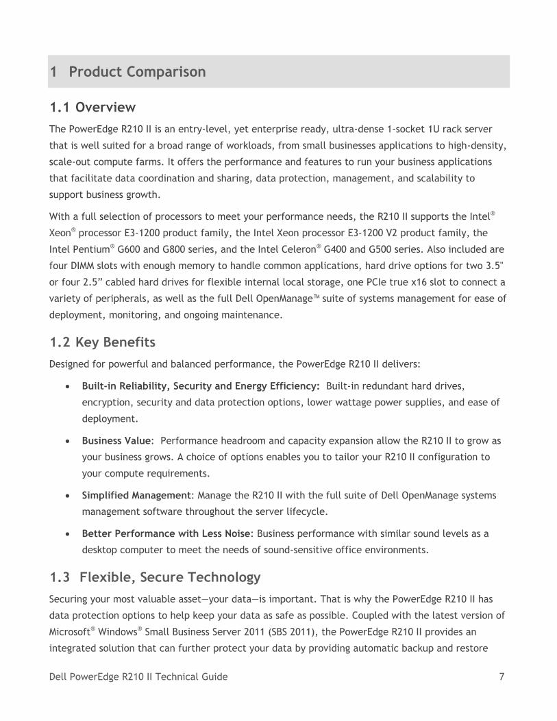
1 Product Comparison
1.1 Overview
The PowerEdge R210 II is an entry-level, yet enterprise ready, ultra-dense 1-socket 1U rack server
that is well suited for a broad range of workloads, from small businesses applications to high-density,
scale-out compute farms. It offers the performance and features to run your business applications
that facilitate data coordination and sharing, data protection, management, and scalability to
support business growth.
With a full selection of processors to meet your performance needs, the R210 II supports the Intel®
Xeon® processor E3-1200 product family, the Intel Xeon processor E3-1200 V2 product family, the
Intel Pentium® G600 and G800 series, and the Intel Celeron® G400 and G500 series. Also included are
four DIMM slots with enough memory to handle common applications, hard drive options for two 3.5"
or four 2.5” cabled hard drives for flexible internal local storage, one PCIe true x16 slot to connect a
variety of peripherals, as well as the full Dell OpenManage™ suite of systems management for ease of
deployment, monitoring, and ongoing maintenance.
1.2 Key Benefits
Designed for powerful and balanced performance, the PowerEdge R210 II delivers:
Built-in Reliability, Security and Energy Efficiency: Built-in redundant hard drives,
encryption, security and data protection options, lower wattage power supplies, and ease of
deployment.
Business Value: Performance headroom and capacity expansion allow the R210 II to grow as
your business grows. A choice of options enables you to tailor your R210 II configuration to
your compute requirements.
Simplified Management: Manage the R210 II with the full suite of Dell OpenManage systems
management software throughout the server lifecycle.
Better Performance with Less Noise: Business performance with similar sound levels as a
desktop computer to meet the needs of sound-sensitive office environments.
1.3 Flexible, Secure Technology
Securing your most valuable asset—your data—is important. That is why the PowerEdge R210 II has
data protection options to help keep your data as safe as possible. Coupled with the latest version of
Microsoft® Windows® Small Business Server 2011 (SBS 2011), the PowerEdge R210 II provides an
integrated solution that can further protect your data by providing automatic backup and restore
Dell PowerEdge R210 II Technical Guide 8
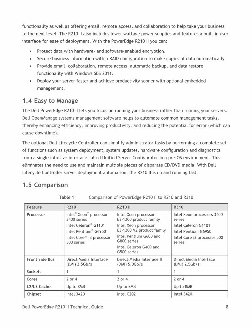
functionality as well as offering email, remote access, and collaboration to help take your business
to the next level. The R210 II also includes lower wattage power supplies and features a built-in user
interface for ease of deployment. With the PowerEdge R210 II you can:
Protect data with hardware- and software-enabled encryption.
Secure business information with a RAID configuration to make copies of data automatically.
Provide email, collaboration, remote access, automatic backup, and data restore
functionality with Windows SBS 2011.
Deploy your server faster and achieve productivity sooner with optional embedded
management.
1.4 Easy to Manage
The Dell PowerEdge R210 II lets you focus on running your business rather than running your servers.
Dell OpenManage systems management software helps to automate common management tasks,
thereby enhancing efficiency, improving productivity, and reducing the potential for error (which can
cause downtime).
The optional Dell Lifecycle Controller can simplify administrator tasks by performing a complete set
of functions such as system deployment, system updates, hardware configuration and diagnostics
from a single intuitive interface called Unified Server Configurator in a pre-OS environment. This
eliminates the need to use and maintain multiple pieces of disparate CD/DVD media. With Dell
Lifecycle Controller server deployment automation, the R210 II is up and running fast.
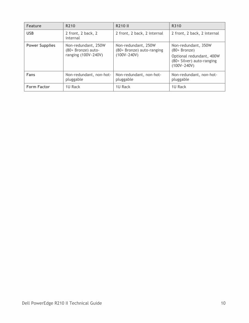
1.5 Comparison
Table 1. Comparison of PowerEdge R210 II to R210 and R310
Feature R210 R210 II R310
Processor Intel® Xeon® processor 3400 series
Intel Celeron® G1101
Intel Pentium® G6950
Intel Core™ i3 processor 500 series
Intel Xeon processor E3-1200 product family
Intel Xeon processor E3-1200 V2 product family
Intel Pentium G600 and G800 series
Intel Celeron G400 and G500 series
Intel Xeon processors 3400 series
Intel Celeron G1101
Intel Pentium G6950
Intel Core i3 processor 500 series
Front Side Bus Direct Media Interface (DMI) 2.5Gb/s
Direct Media Interface II (DMI) 5.0Gb/s
Direct Media Interface (DMI) 2.5Gb/s
Sockets 1 1 1
Cores 2 or 4 2 or 4 2 or 4
L2/L3 Cache Up to 8MB Up to 8MB Up to 8MB
Chipset Intel 3420 Intel C202 Intel 3420
Dell PowerEdge R210 II Technical Guide 9
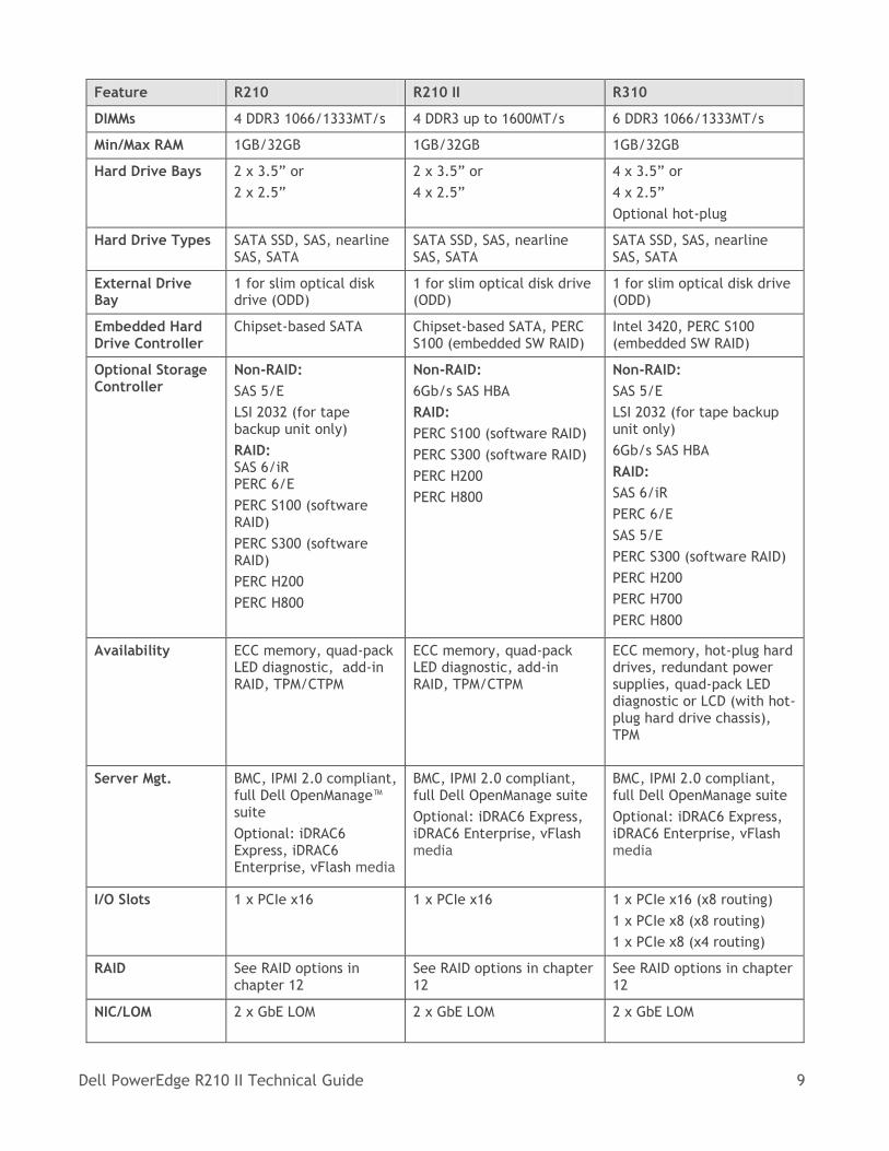
Feature R210 R210 II R310
DIMMs 4 DDR3 1066/1333MT/s 4 DDR3 up to 1600MT/s 6 DDR3 1066/1333MT/s
Min/Max RAM 1GB/32GB 1GB/32GB 1GB/32GB
Hard Drive Bays 2 x 3.5” or
2 x 2.5”
2 x 3.5” or
4 x 2.5”
4 x 3.5” or
4 x 2.5”
Optional hot-plug
Hard Drive Types SATA SSD, SAS, nearline SAS, SATA
SATA SSD, SAS, nearline SAS, SATA
SATA SSD, SAS, nearline SAS, SATA
External Drive Bay
1 for slim optical disk drive (ODD)
1 for slim optical disk drive (ODD)
1 for slim optical disk drive (ODD)
Embedded Hard Drive Controller
Chipset-based SATA Chipset-based SATA, PERC S100 (embedded SW RAID)
Intel 3420, PERC S100 (embedded SW RAID)
Optional Storage Controller
Non-RAID:
SAS 5/E
LSI 2032 (for tape backup unit only)
RAID: SAS 6/iR PERC 6/E
PERC S100 (software RAID)
PERC S300 (software RAID)
PERC H200
PERC H800
Non-RAID:
6Gb/s SAS HBA
RAID:
PERC S100 (software RAID)
PERC S300 (software RAID)
PERC H200
PERC H800
Non-RAID:
SAS 5/E
LSI 2032 (for tape backup unit only)
6Gb/s SAS HBA
RAID:
SAS 6/iR
PERC 6/E
SAS 5/E
PERC S300 (software RAID)
PERC H200
PERC H700
PERC H800
Availability ECC memory, quad-pack LED diagnostic, add-in RAID, TPM/CTPM
ECC memory, quad-pack LED diagnostic, add-in RAID, TPM/CTPM
ECC memory, hot-plug hard drives, redundant power supplies, quad-pack LED diagnostic or LCD (with hot-plug hard drive chassis), TPM
Server Mgt. BMC, IPMI 2.0 compliant, full Dell OpenManage™ suite
Optional: iDRAC6 Express, iDRAC6 Enterprise, vFlash media
BMC, IPMI 2.0 compliant, full Dell OpenManage suite
Optional: iDRAC6 Express, iDRAC6 Enterprise, vFlash media
BMC, IPMI 2.0 compliant, full Dell OpenManage suite
Optional: iDRAC6 Express, iDRAC6 Enterprise, vFlash media
I/O Slots 1 x PCIe x16 1 x PCIe x16 1 x PCIe x16 (x8 routing)
1 x PCIe x8 (x8 routing)
1 x PCIe x8 (x4 routing)
RAID See RAID options in chapter 12
See RAID options in chapter 12
See RAID options in chapter 12
NIC/LOM 2 x GbE LOM 2 x GbE LOM 2 x GbE LOM
Dell PowerEdge R210 II Technical Guide 10
Feature R210 R210 II R310
USB 2 front, 2 back, 2 internal
2 front, 2 back, 2 internal 2 front, 2 back, 2 internal
Power Supplies Non-redundant, 250W (80+ Bronze) auto-ranging (100V~240V)
Non-redundant, 250W (80+ Bronze) auto-ranging (100V~240V)
Non-redundant, 350W (80+ Bronze)
Optional redundant, 400W (80+ Silver) auto-ranging (100V~240V)
Fans Non-redundant, non-hot- pluggable
Non-redundant, non-hot- pluggable
Non-redundant, non-hot- pluggable
Form Factor 1U Rack 1U Rack 1U Rack
Dell PowerEdge R210 II Technical Guide 11
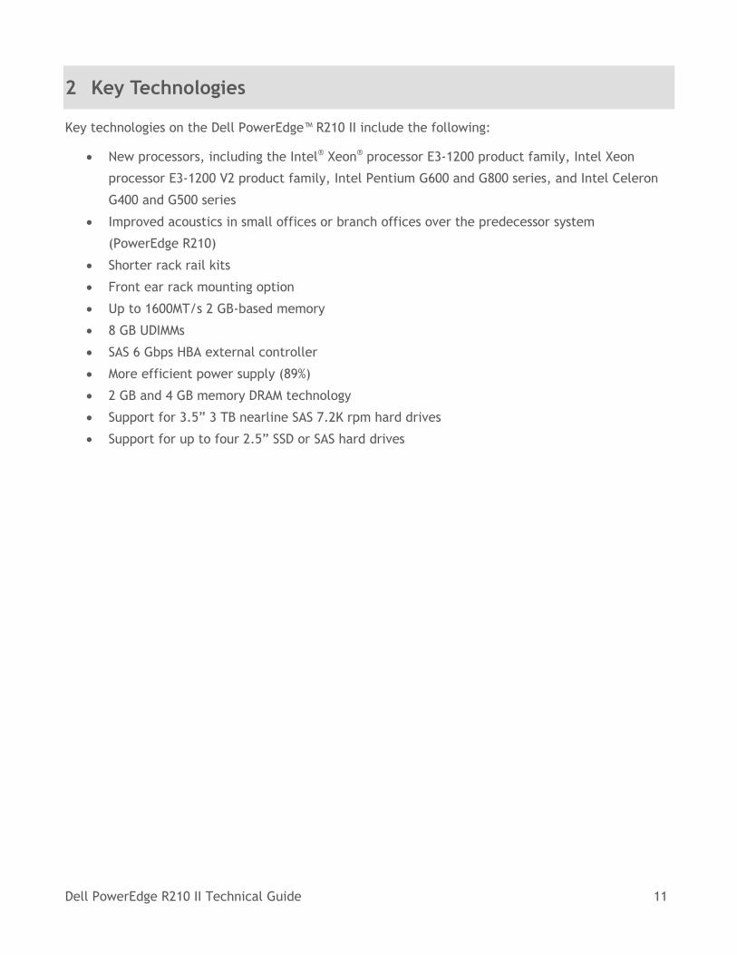
2 Key Technologies
Key technologies on the Dell PowerEdge™ R210 II include the following:
New processors, including the Intel® Xeon® processor E3-1200 product family, Intel Xeon
processor E3-1200 V2 product family, Intel Pentium G600 and G800 series, and Intel Celeron
G400 and G500 series
Improved acoustics in small offices or branch offices over the predecessor system
(PowerEdge R210)
Shorter rack rail kits
Front ear rack mounting option
Up to 1600MT/s 2 GB-based memory
8 GB UDIMMs
SAS 6 Gbps HBA external controller
More efficient power supply (89%)
2 GB and 4 GB memory DRAM technology
Support for 3.5” 3 TB nearline SAS 7.2K rpm hard drives
Support for up to four 2.5” SSD or SAS hard drives
Dell PowerEdge R210 II Technical Guide 12
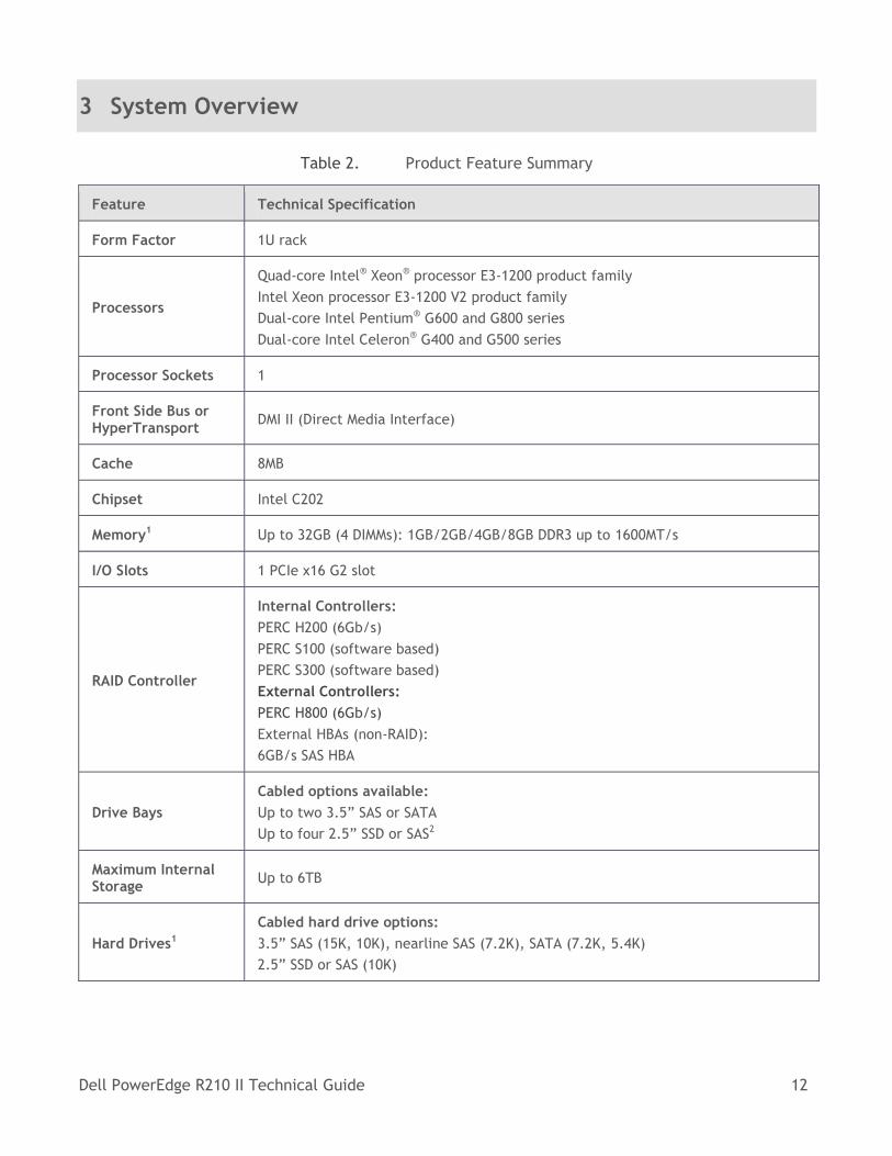
3 System Overview
Table 2. Product Feature Summary
Feature Technical Specification
Form Factor 1U rack
Processors
Quad-core Intel® Xeon® processor E3-1200 product family
Intel Xeon processor E3-1200 V2 product family
Dual-core Intel Pentium® G600 and G800 series
Dual-core Intel Celeron® G400 and G500 series
Processor Sockets 1
Front Side Bus or HyperTransport
DMI II (Direct Media Interface)
Cache 8MB
Chipset Intel C202
Memory1 Up to 32GB (4 DIMMs): 1GB/2GB/4GB/8GB DDR3 up to 1600MT/s
I/O Slots 1 PCIe x16 G2 slot
RAID Controller
Internal Controllers:
PERC H200 (6Gb/s)
PERC S100 (software based)
PERC S300 (software based)
External Controllers:
PERC H800 (6Gb/s)
External HBAs (non-RAID):
6GB/s SAS HBA
Drive Bays
Cabled options available:
Up to two 3.5” SAS or SATA
Up to four 2.5” SSD or SAS2
Maximum Internal Storage
Up to 6TB
Hard Drives1
Cabled hard drive options:
3.5” SAS (15K, 10K), nearline SAS (7.2K), SATA (7.2K, 5.4K)
2.5” SSD or SAS (10K)
Dell PowerEdge R210 II Technical Guide 13
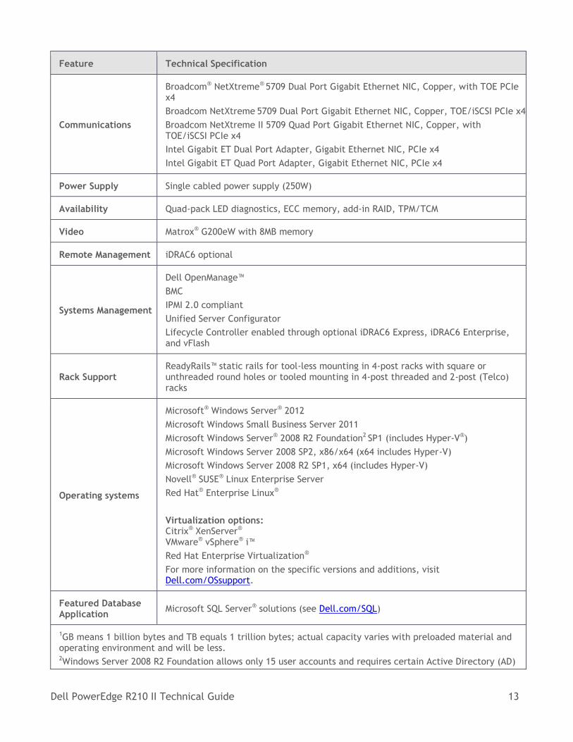
Feature Technical Specification
Communications
Broadcom® NetXtreme® 5709 Dual Port Gigabit Ethernet NIC, Copper, with TOE PCIe x4
Broadcom NetXtreme 5709 Dual Port Gigabit Ethernet NIC, Copper, TOE/iSCSI PCIe x4
Broadcom NetXtreme II 5709 Quad Port Gigabit Ethernet NIC, Copper, with TOE/iSCSI PCIe x4
Intel Gigabit ET Dual Port Adapter, Gigabit Ethernet NIC, PCIe x4
Intel Gigabit ET Quad Port Adapter, Gigabit Ethernet NIC, PCIe x4
Power Supply Single cabled power supply (250W)
Availability Quad-pack LED diagnostics, ECC memory, add-in RAID, TPM/TCM
Video Matrox® G200eW with 8MB memory
Remote Management iDRAC6 optional
Systems Management
Dell OpenManage™
BMC
IPMI 2.0 compliant
Unified Server Configurator
Lifecycle Controller enabled through optional iDRAC6 Express, iDRAC6 Enterprise, and vFlash
Rack Support ReadyRails™ static rails for tool-less mounting in 4-post racks with square or unthreaded round holes or tooled mounting in 4-post threaded and 2-post (Telco) racks
Operating systems
Microsoft® Windows Server® 2012
Microsoft Windows Small Business Server 2011
Microsoft Windows Server® 2008 R2 Foundation2 SP1 (includes Hyper-V®)
Microsoft Windows Server 2008 SP2, x86/x64 (x64 includes Hyper-V)
Microsoft Windows Server 2008 R2 SP1, x64 (includes Hyper-V)
Novell® SUSE® Linux Enterprise Server
Red Hat® Enterprise Linux®
Virtualization options: Citrix® XenServer® VMware® vSphere® i™
Red Hat Enterprise Virtualization®
For more information on the specific versions and additions, visit Dell.com/OSsupport.
Featured Database Application
Microsoft SQL Server® solutions (see Dell.com/SQL)
1GB means 1 billion bytes and TB equals 1 trillion bytes; actual capacity varies with preloaded material and operating environment and will be less. 2Windows Server 2008 R2 Foundation allows only 15 user accounts and requires certain Active Directory (AD)
Dell PowerEdge R210 II Technical Guide 14
Feature Technical Specification
configurations. If not configured according to the product documentation, the software will generate warnings to correct the configuration. After a certain amount of time, the software will only run for one hour at a time until the configuration is corrected. For more information about these features review the product documentation located at go.microsoft.com/fwlink/?LinkId=143551
Dell PowerEdge R210 II Technical Guide 15
4 Mechanical
4.1 Chassis Description
The PowerEdge R210 II is a 1U rack-mount design that supports the following features:
Two cabled 3.5” drive bays for SATA or SAS hard drives or four 2.5” drive bays for SAS or SSD drives
Dual Gigabit LAN on motherboard (LOM)
Four DIMM slots
TPM security feature
One riser card for optional PCIe expansion card
Optional iDRAC6 Enterprise and iDRAC6 Express card mounted on planar (without PCI slot occupied)
Support for slim static and slim sliding rails
Single non-redundant power supply
Diagnostic LED panel
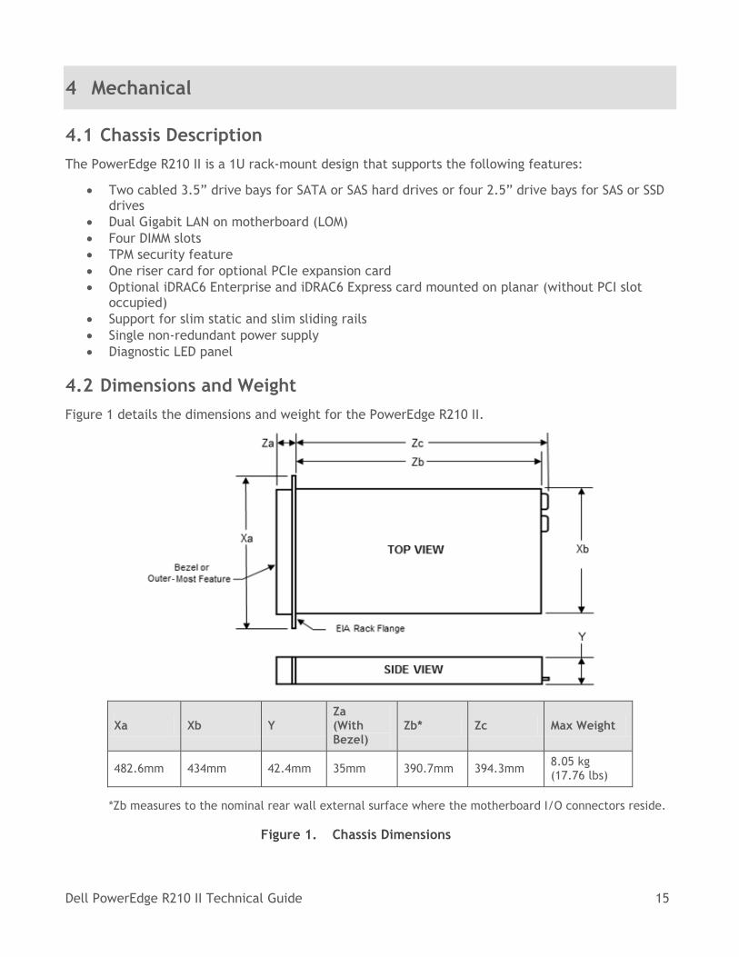
4.2 Dimensions and Weight
Figure 1 details the dimensions and weight for the PowerEdge R210 II.
Xa Xb Y Za (With Bezel)
Zb* Zc Max Weight
482.6mm 434mm 42.4mm 35mm 390.7mm 394.3mm 8.05 kg (17.76 lbs)
*Zb measures to the nominal rear wall external surface where the motherboard I/O connectors reside.
Figure 1. Chassis Dimensions
Dell PowerEdge R210 II Technical Guide 16
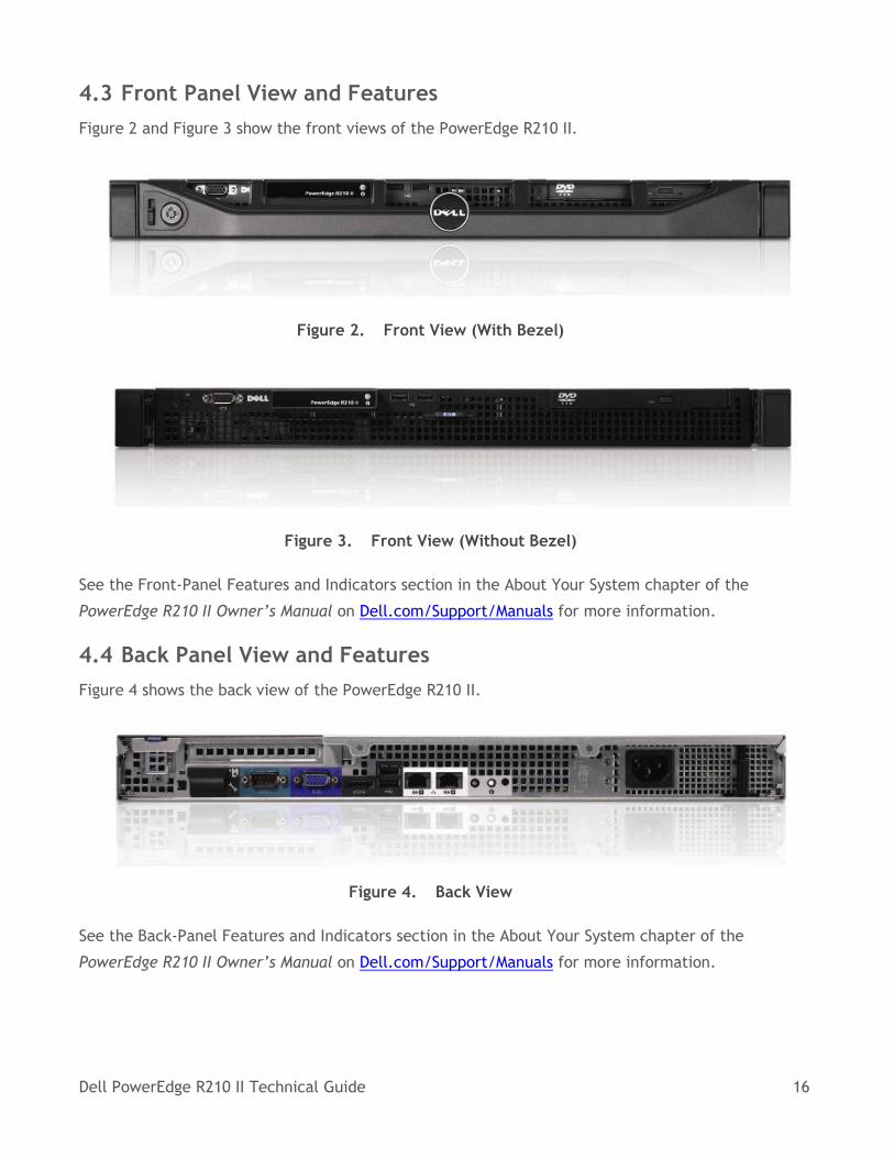
4.3 Front Panel View and Features
Figure 2 and Figure 3 show the front views of the PowerEdge R210 II.
Figure 2. Front View (With Bezel)
Figure 3. Front View (Without Bezel)
See the Front-Panel Features and Indicators section in the About Your System chapter of the
PowerEdge R210 II Owner’s Manual on Dell.com/Support/Manuals for more information.
4.4 Back Panel View and Features
Figure 4 shows the back view of the PowerEdge R210 II.
Figure 4. Back View
See the Back-Panel Features and Indicators section in the About Your System chapter of the
PowerEdge R210 II Owner’s Manual on Dell.com/Support/Manuals for more information.
Dell PowerEdge R210 II Technical Guide 17
4.5 Power Button LED
All Dell PowerEdge servers have a green LED integrated in the power button which indicates the
system’s power state.
Figure 5. Power Button
See the About Your System chapter of the PowerEdge R210 II Owner’s Manual on
Dell.com/Support/Manuals for more information.
4.6 System Status ID
The System Status ID indicators are two LEDs—one on the front panel of the system and one on the
back panel. These LEDs indicates the system state.
See the About Your System chapter of the PowerEdge R210 II Owner’s Manual on
Dell.com/Support/Manuals for more information.
4.7 NIC Indicators
See the NIC Indicator Codes section in the About Your System chapter of the PowerEdge R210 II
Owner’s Manual on Dell.com/Support/Manuals for more information.
4.8 Internal Chassis Views
Figure 6 shows the internal view of the PowerEdge R210 II server.
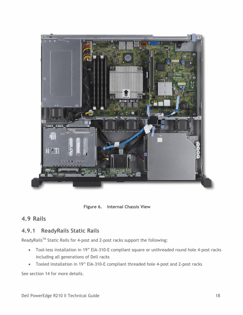
Dell PowerEdge R210 II Technical Guide 18
Figure 6. Internal Chassis View
4.9 Rails
4.9.1 ReadyRails Static Rails
ReadyRailsTM Static Rails for 4-post and 2-post racks support the following:
Tool-less installation in 19” EIA-310-E compliant square or unthreaded round hole 4-post racks
including all generations of Dell racks
Tooled installation in 19” EIA-310-E compliant threaded hole 4-post and 2-post racks
See section 14 for more details.
Dell PowerEdge R210 II Technical Guide 19
4.10 Fans
There are three system fans located in the R210 II system.
For information on removing and installing the system fans, see the Installing System Components
chapter of the PowerEdge R210 II Owner’s Manual on Dell.com/Support/Manuals for more
information.
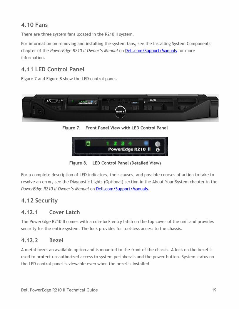
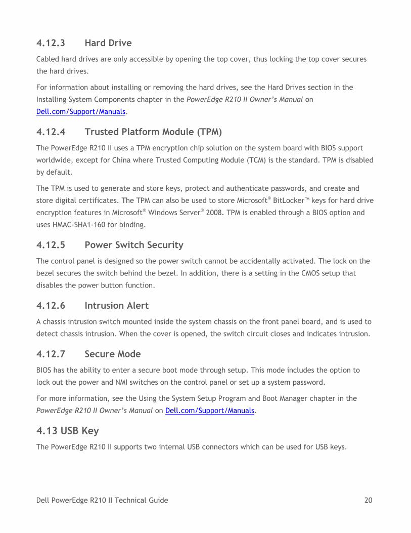
4.11 LED Control Panel
Figure 7 and Figure 8 show the LED control panel.
Figure 7. Front Panel View with LED Control Panel
Figure 8. LED Control Panel (Detailed View)
For a complete description of LED indicators, their causes, and possible courses of action to take to
resolve an error, see the Diagnostic Lights (Optional) section in the About Your System chapter in the
PowerEdge R210 II Owner’s Manual on Dell.com/Support/Manuals.
4.12 Security
4.12.1 Cover Latch
The PowerEdge R210 II comes with a coin-lock entry latch on the top cover of the unit and provides
security for the entire system. The lock provides for tool-less access to the chassis.
4.12.2 Bezel
A metal bezel an available option and is mounted to the front of the chassis. A lock on the bezel is
used to protect un-authorized access to system peripherals and the power button. System status on
the LED control panel is viewable even when the bezel is installed.
Dell PowerEdge R210 II Technical Guide 20
4.12.3 Hard Drive
Cabled hard drives are only accessible by opening the top cover, thus locking the top cover secures
the hard drives.
For information about installing or removing the hard drives, see the Hard Drives section in the
Installing System Components chapter in the PowerEdge R210 II Owner’s Manual on
Dell.com/Support/Manuals.
4.12.4 Trusted Platform Module (TPM)
The PowerEdge R210 II uses a TPM encryption chip solution on the system board with BIOS support
worldwide, except for China where Trusted Computing Module (TCM) is the standard. TPM is disabled
by default.
The TPM is used to generate and store keys, protect and authenticate passwords, and create and
store digital certificates. The TPM can also be used to store Microsoft® BitLocker™ keys for hard drive
encryption features in Microsoft® Windows Server® 2008. TPM is enabled through a BIOS option and
uses HMAC-SHA1-160 for binding.
4.12.5 Power Switch Security
The control panel is designed so the power switch cannot be accidentally activated. The lock on the
bezel secures the switch behind the bezel. In addition, there is a setting in the CMOS setup that
disables the power button function.
4.12.6 Intrusion Alert
A chassis intrusion switch mounted inside the system chassis on the front panel board, and is used to
detect chassis intrusion. When the cover is opened, the switch circuit closes and indicates intrusion.
4.12.7 Secure Mode
BIOS has the ability to enter a secure boot mode through setup. This mode includes the option to
lock out the power and NMI switches on the control panel or set up a system password.
For more information, see the Using the System Setup Program and Boot Manager chapter in the
PowerEdge R210 II Owner’s Manual on Dell.com/Support/Manuals.
4.13 USB Key
The PowerEdge R210 II supports two internal USB connectors which can be used for USB keys.
Dell PowerEdge R210 II Technical Guide 21
4.14 Battery
A replaceable coin cell CR2032 3V battery is mounted on the planar to provide backup power for the
Real-Time Clock and CMOS RAM on the Intel® SP5100 chip.
4.14.1 Field Replaceable Units (FRU)
The planar contains a serial EEPROM to store Field Replaceable Unit (FRU) information including Dell
part numbers, part revision levels, and serial numbers. This information is used by the SEL (system
event log) and the BMC (baseboard management controller).
4.15 User Accessible Jumpers, Sockets, and Connectors
See the Jumpers and Connectors chapter in the PowerEdge R210 II Owner’s Manual on
Dell.com/Support/Manuals.
Dell PowerEdge R210 II Technical Guide 22
5 Power, Thermal, Acoustic
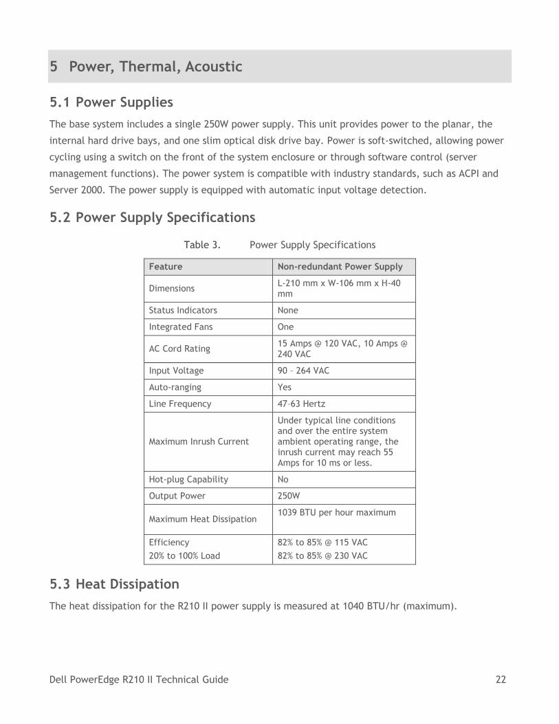
5.1 Power Supplies
The base system includes a single 250W power supply. This unit provides power to the planar, the
internal hard drive bays, and one slim optical disk drive bay. Power is soft-switched, allowing power
cycling using a switch on the front of the system enclosure or through software control (server
management functions). The power system is compatible with industry standards, such as ACPI and
Server 2000. The power supply is equipped with automatic input voltage detection.
5.2 Power Supply Specifications
Table 3. Power Supply Specifications
Feature Non-redundant Power Supply
Dimensions L-210 mm x W-106 mm x H-40 mm
Status Indicators None
Integrated Fans One
AC Cord Rating 15 Amps @ 120 VAC, 10 Amps @ 240 VAC
Input Voltage 90 – 264 VAC
Auto-ranging Yes
Line Frequency 47–63 Hertz
Maximum Inrush Current
Under typical line conditions and over the entire system ambient operating range, the inrush current may reach 55 Amps for 10 ms or less.
Hot-plug Capability No
Output Power 250W
Maximum Heat Dissipation 1039 BTU per hour maximum
Efficiency
20% to 100% Load
82% to 85% @ 115 VAC
82% to 85% @ 230 VAC
5.3 Heat Dissipation
The heat dissipation for the R210 II power supply is measured at 1040 BTU/hr (maximum).
Dell PowerEdge R210 II Technical Guide 23
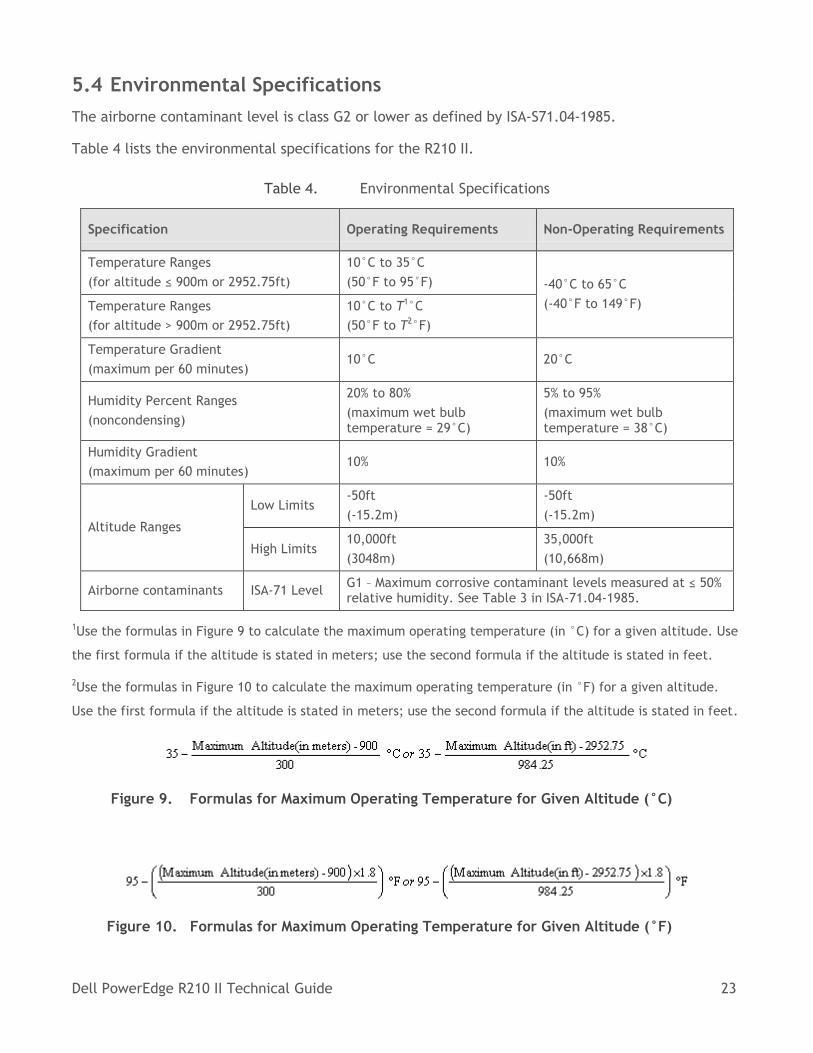
5.4 Environmental Specifications
The airborne contaminant level is class G2 or lower as defined by ISA-S71.04-1985.
Table 4 lists the environmental specifications for the R210 II.
Table 4. Environmental Specifications
Specification Operating Requirements Non-Operating Requirements
Temperature Ranges
(for altitude ≤ 900m or 2952.75ft)
10°C to 35°C
(50°F to 95°F) -40°C to 65°C
(-40°F to 149°F) Temperature Ranges
(for altitude > 900m or 2952.75ft)
10°C to T1°C
(50°F to T2°F)
Temperature Gradient
(maximum per 60 minutes) 10°C 20°C
Humidity Percent Ranges
(noncondensing)
20% to 80%
(maximum wet bulb temperature = 29°C)
5% to 95%
(maximum wet bulb temperature = 38°C)
Humidity Gradient
(maximum per 60 minutes) 10% 10%
Altitude Ranges
Low Limits -50ft
(-15.2m)
-50ft
(-15.2m)
High Limits 10,000ft
(3048m)
35,000ft
(10,668m)
Airborne contaminants ISA-71 Level G1 – Maximum corrosive contaminant levels measured at ≤ 50% relative humidity. See Table 3 in ISA-71.04-1985.
1Use the formulas in Figure 9 to calculate the maximum operating temperature (in °C) for a given altitude. Use
the first formula if the altitude is stated in meters; use the second formula if the altitude is stated in feet.
2Use the formulas in Figure 10 to calculate the maximum operating temperature (in °F) for a given altitude.
Use the first formula if the altitude is stated in meters; use the second formula if the altitude is stated in feet.
Figure 9. Formulas for Maximum Operating Temperature for Given Altitude (°C)
Figure 10. Formulas for Maximum Operating Temperature for Given Altitude (°F)
Dell PowerEdge R210 II Technical Guide 24
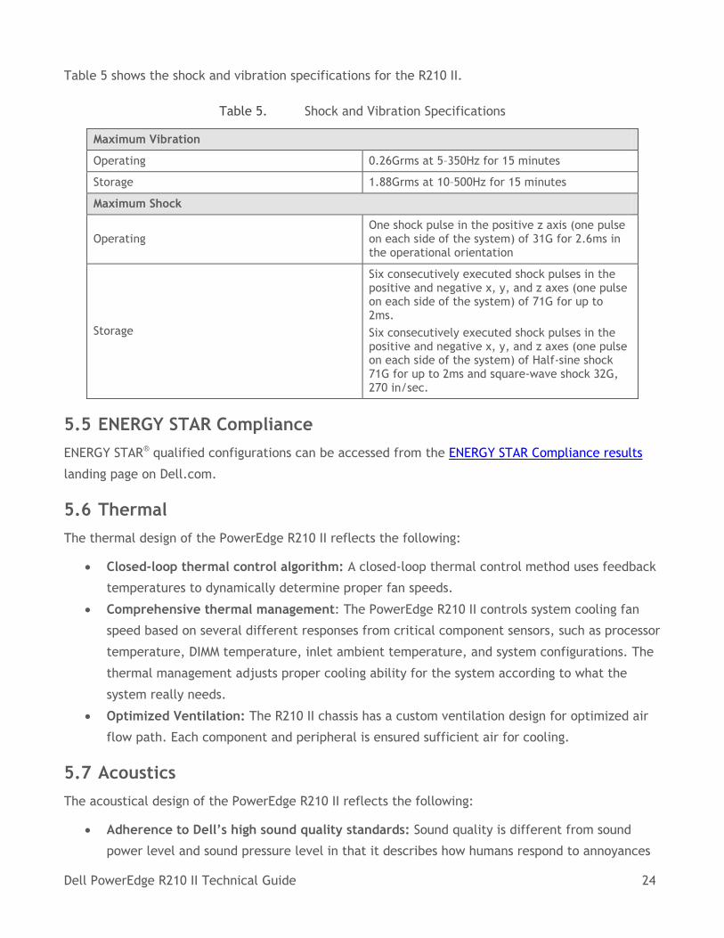
Table 5 shows the shock and vibration specifications for the R210 II.
Table 5. Shock and Vibration Specifications
Maximum Vibration
Operating 0.26Grms at 5–350Hz for 15 minutes
Storage 1.88Grms at 10–500Hz for 15 minutes
Maximum Shock
Operating One shock pulse in the positive z axis (one pulse on each side of the system) of 31G for 2.6ms in the operational orientation
Storage
Six consecutively executed shock pulses in the positive and negative x, y, and z axes (one pulse on each side of the system) of 71G for up to 2ms.
Six consecutively executed shock pulses in the positive and negative x, y, and z axes (one pulse on each side of the system) of Half-sine shock 71G for up to 2ms and square-wave shock 32G, 270 in/sec.
5.5 ENERGY STAR Compliance
ENERGY STAR® qualified configurations can be accessed from the ENERGY STAR Compliance results
landing page on Dell.com.
5.6 Thermal
The thermal design of the PowerEdge R210 II reflects the following:
Closed-loop thermal control algorithm: A closed-loop thermal control method uses feedback
temperatures to dynamically determine proper fan speeds.
Comprehensive thermal management: The PowerEdge R210 II controls system cooling fan
speed based on several different responses from critical component sensors, such as processor
temperature, DIMM temperature, inlet ambient temperature, and system configurations. The
thermal management adjusts proper cooling ability for the system according to what the
system really needs.
Optimized Ventilation: The R210 II chassis has a custom ventilation design for optimized air
flow path. Each component and peripheral is ensured sufficient air for cooling.
5.7 Acoustics
The acoustical design of the PowerEdge R210 II reflects the following:
Adherence to Dell’s high sound quality standards: Sound quality is different from sound
power level and sound pressure level in that it describes how humans respond to annoyances
Dell PowerEdge R210 II Technical Guide 25
in sound, like whistles and hums. One of the sound quality metrics in the Dell specification is
the prominence ratio of a tone, which is listed in Table 6.
Office environment acoustics: Compare the values for LpA in Table 6 and note that they are
lower than ambient measurements of typical office environments.
Hardware configurations affect system noise levels: Dell’s thermal control provides for
cooling flexible to varying hardware configurations. Acoustical performance associated with
two common configurations is listed in Table 6.
Noise ramp and descent at boot: Fan speeds (and corresponding noise levels) ramp up during
the boot process to add a layer of protection for component cooling, in the event that the
system does not boot properly.
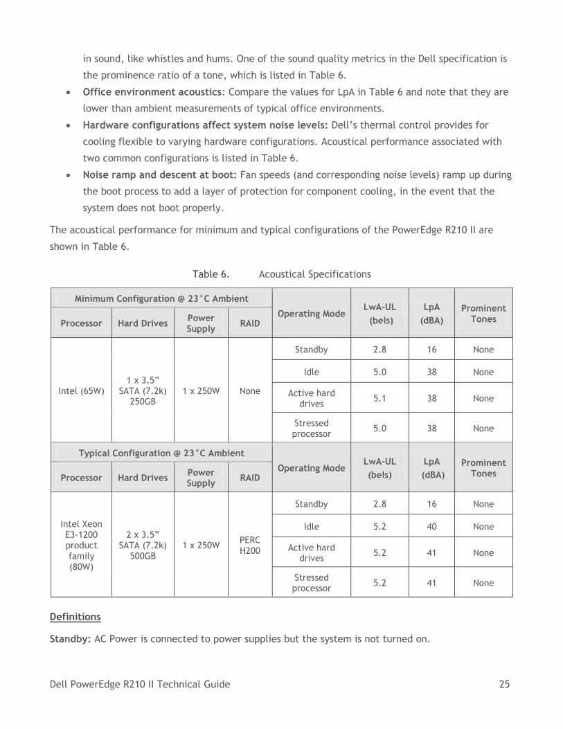
The acoustical performance for minimum and typical configurations of the PowerEdge R210 II are
shown in Table 6.
Table 6. Acoustical Specifications
Minimum Configuration @ 23°C Ambient
Operating Mode LwA-UL
(bels)
LpA
(dBA)
Prominent Tones Processor Hard Drives
Power Supply
RAID
Intel (65W) 1 x 3.5”
SATA (7.2k) 250GB
1 x 250W None
Standby 2.8 16 None
Idle 5.0 38 None
Active hard drives
5.1 38 None
Stressed processor
5.0 38 None
Typical Configuration @ 23°C Ambient
Operating Mode LwA-UL
(bels)
LpA
(dBA)
Prominent Tones Processor Hard Drives
Power Supply
RAID
Intel Xeon E3-1200 product family (80W)
2 x 3.5” SATA (7.2k)
500GB 1 x 250W
PERC H200
Standby 2.8 16 None
Idle 5.2 40 None
Active hard drives
5.2 41 None
Stressed processor
5.2 41 None
Definitions
Standby: AC Power is connected to power supplies but the system is not turned on.
Dell PowerEdge R210 II Technical Guide 26
Idle: Reference ISO7779 (1999) definition 3.1.7; system is running in its OS but no other specific
activity.
Active Hard Drives: An operating mode per ISO7779 (1999) definition 3.1.6; Section C.9 of ECMA-74
9th ed. (2005) is followed in exercising the hard disk drives.
Stressed Processor: An operating mode per ISO7779 (1999) definition 3.1.6; SPECPower set to 50%
loading is used.
LwA–UL: The upper limit sound power level (LwA) calculated per section 4.4.2 of ISO 9296 (1988) and
measured in accordance to ISO 7779 (1999).
LpA-Op: A-Weighted sound pressure level. The system is placed in center of ISO7779 table, while the
acoustic transducer is located 150 cm above the floor and 50 cm in front of the equipment.
Prominent tones: Criteria of D.6 and D.11 of ECMA-74 11th ed. (2010) are followed to determine if
discrete tones are prominent. The system is placed in a rack with its bottom at 75-cm from the floor.
The acoustic transducer is at front bystander position, ref ISO7779 3rd (2010), Section 8.6.2.
Dell PowerEdge R210 II Technical Guide 27
6 Processors
6.1 Overview
The processors for the R210 II are based on the latest two- and four-core offerings from the Intel®
Xeon® processor E3-1200 product family, Intel Xeon processor E3-1200 V2 product family, Intel
Pentium® G600 and G800 series, and Intel Celeron® G400 and G500 series.
6.2 Features
Key features of the R210 II processors include:
New microarchitecture on 32nm process delivers higher performance and lower power.
Intel® Advanced Vector Extensions (AVX) allows for better acceleration of floating point
intensive applications.
Next generation Intel Turbo Boost Technology maximizes processor performance during
workload spikes by allowing the processor to briefly operate above TDP.
New Advanced Encryption Standard (AES) provides improved encryption and decryption
performance.
Increased processor performance of up to 25% over previous generation.
Memory and I/O: 2x memory footprint at 32GB; 4 additional PCIe lanes (2.0).
Storage: 6 SATA 3Gb/s ports.
Efficiency: Low power Intel Xeon® processor options.
Reliability: Error Correcting Code (ECC) memory to improve data integrity.
Server validation: With server operating systems, server class peripherals and adapters to
ensure compatibility.
Storage: RAID support for Linux operating systems.
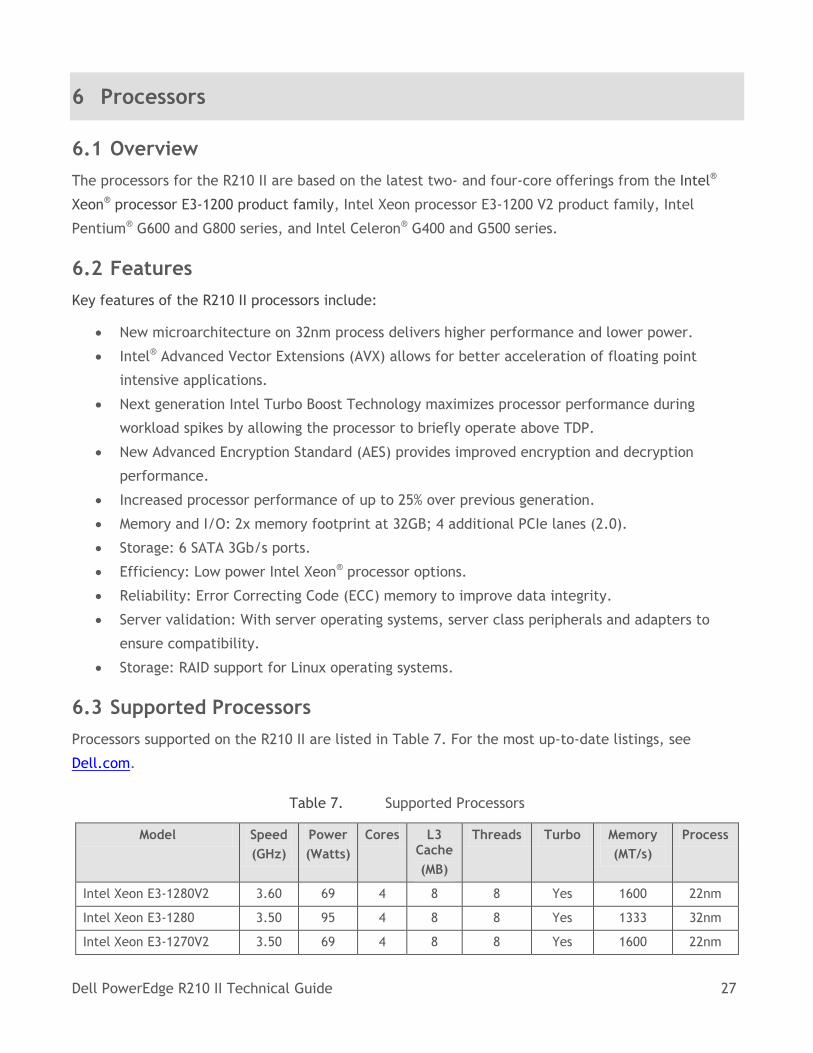
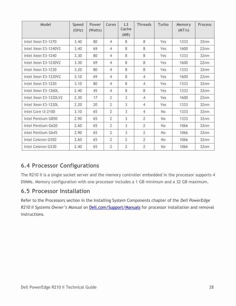
6.3 Supported Processors
Processors supported on the R210 II are listed in Table 7. For the most up-to-date listings, see
Dell.com.
Table 7. Supported Processors
Model Speed
(GHz)
Power
(Watts)
Cores L3 Cache
(MB)
Threads Turbo Memory
(MT/s)
Process
Intel Xeon E3-1280V2 3.60 69 4 8 8 Yes 1600 22nm
Intel Xeon E3-1280 3.50 95 4 8 8 Yes 1333 32nm
Intel Xeon E3-1270V2 3.50 69 4 8 8 Yes 1600 22nm
Dell PowerEdge R210 II Technical Guide 28
Model Speed
(GHz)
Power
(Watts)
Cores L3 Cache
(MB)
Threads Turbo Memory
(MT/s)
Process
Intel Xeon E3-1270 3.40 80 4 8 8 Yes 1333 32nm
Intel Xeon E3-1240V2 3.40 69 4 8 8 Yes 1600 22nm
Intel Xeon E3-1240 3.30 80 4 8 8 Yes 1333 32nm
Intel Xeon E3-1230V2 3.30 69 4 8 8 Yes 1600 22nm
Intel Xeon E3-1230 3.20 80 4 8 8 Yes 1333 32nm
Intel Xeon E3-1220V2 3.10 69 4 8 4 Yes 1600 22nm
Intel Xeon E3-1220 3.10 80 4 8 4 Yes 1333 32nm
Intel Xeon E3-1260L 2.40 45 4 8 8 Yes 1333 32nm
Intel Xeon E3-1220LV2 2.30 17 2 3 4 Yes 1600 22nm
Intel Xeon E3-1220L 2.20 20 2 3 4 Yes 1333 32nm
Intel Core i3-2100 3.10 65 2 3 4 No 1333 32nm
Intel Pentium G850 2.90 65 2 3 2 No 1333 32nm
Intel Pentium G620 2.60 65 2 3 2 No 1066 32nm
Intel Pentium G645 2.90 65 2 3 2 No 1066 32nm
Intel Celeron G550 2.60 65 2 2 2 No 1066 32nm
Intel Celeron G530 2.40 65 2 2 2 No 1066 32nm
6.4 Processor Configurations
The R210 II is a single socket server and the memory controller embedded in the processor supports 4
DIMMs. Memory configuration with one processor includes a 1 GB minimum and a 32 GB maximum.
6.5 Processor Installation
Refer to the Processors section in the Installing System Components chapter of the Dell PowerEdge
R210 II Systems Owner’s Manual on Dell.com/Support/Manuals for processor installation and removal
instructions.
Dell PowerEdge R210 II Technical Guide 29
7 Memory
7.1 Overview
The R210 II supports DDR3 memory, providing a high performance, high speed memory interface
capable of low latency response and high throughput. For the Intel processor-based R210 II, up to 4
total DIMMs are supported. Additional specifics regarding memory include:
2Gb DRAM technology
2 channels per processor
Unbuffered (UDIMM) ECC DDR3 DIMMs
DDR3 speeds of up to 1600MT/s (UDIMM only)
Single- and dual-rank UDIMMs (all channels in a system run at the fastest common frequency)
Support for up to 32GB UDIMM memory (4 x 8GB UDIMMs)
Single DIMM configuration only with DIMM in socket A1
No support for quad-rank DIMMs
No RDIMM support
Low-voltage (LV) DIMM supported @ 3.5V only
Non-ECC DIMMs not supported
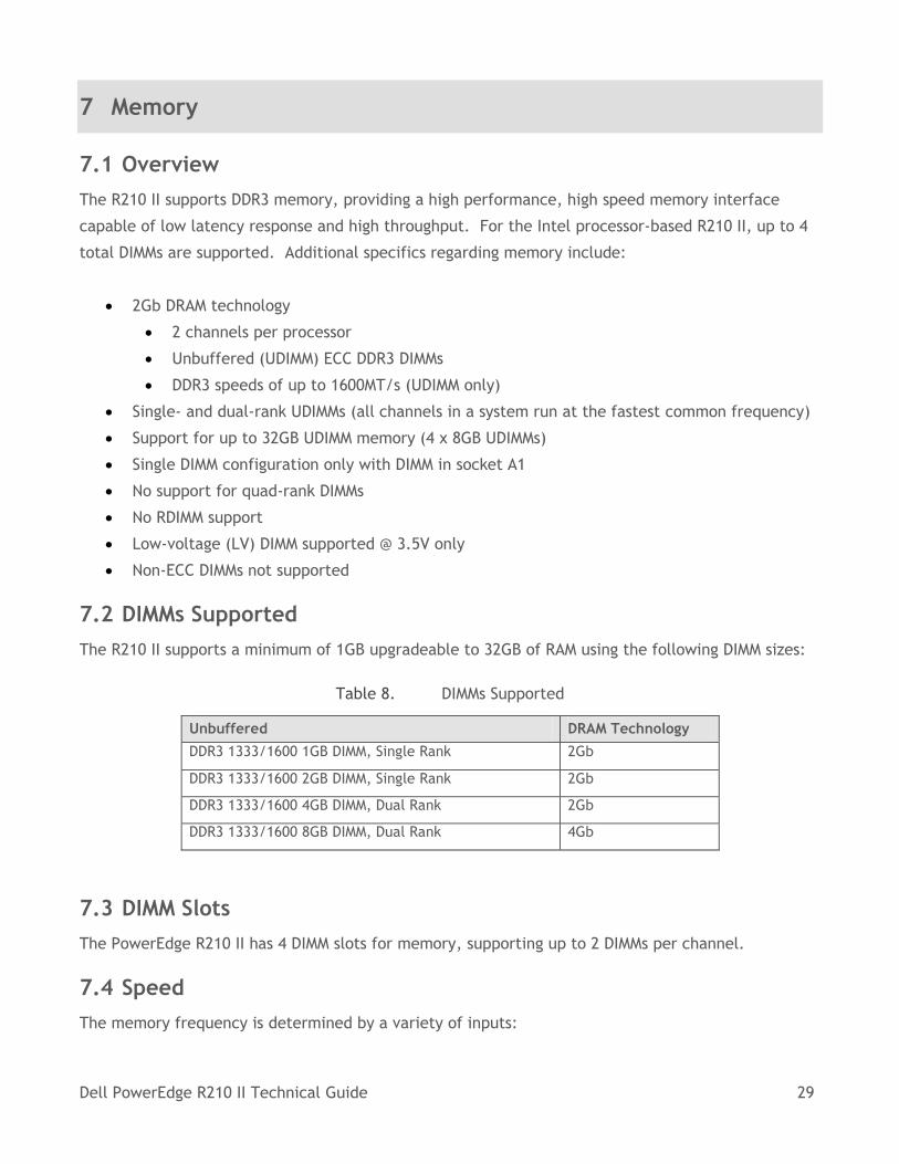
7.2 DIMMs Supported
The R210 II supports a minimum of 1GB upgradeable to 32GB of RAM using the following DIMM sizes:
Table 8. DIMMs Supported
Unbuffered DRAM Technology
DDR3 1333/1600 1GB DIMM, Single Rank 2Gb
DDR3 1333/1600 2GB DIMM, Single Rank 2Gb
DDR3 1333/1600 4GB DIMM, Dual Rank 2Gb
DDR3 1333/1600 8GB DIMM, Dual Rank 4Gb
7.3 DIMM Slots
The PowerEdge R210 II has 4 DIMM slots for memory, supporting up to 2 DIMMs per channel.
7.4 Speed
The memory frequency is determined by a variety of inputs:
Dell PowerEdge R210 II Technical Guide 30
Speed of the DIMMs
Speed supported by the processor
Configuration of the DIMMs
The memory speed of each channel depends on the memory configuration:
For single-rank memory modules
o One memory module per channel supports up to 1600 MT/s
o Two memory modules per channel support up to 1600 MT/s
For dual-rank memory modules
o One memory module per channel supports up to 1600MT/s
o Two memory modules per channel support up to 1600MT/s
If memory modules with different speeds are installed, they will operate at the speed of the slowest
installed memory module(s).
7.5 Sparing
Memory sparing is not supported.
7.6 Mirroring
Memory mirroring is not supported.
7.7 RAID
Memory RAID is not supported.
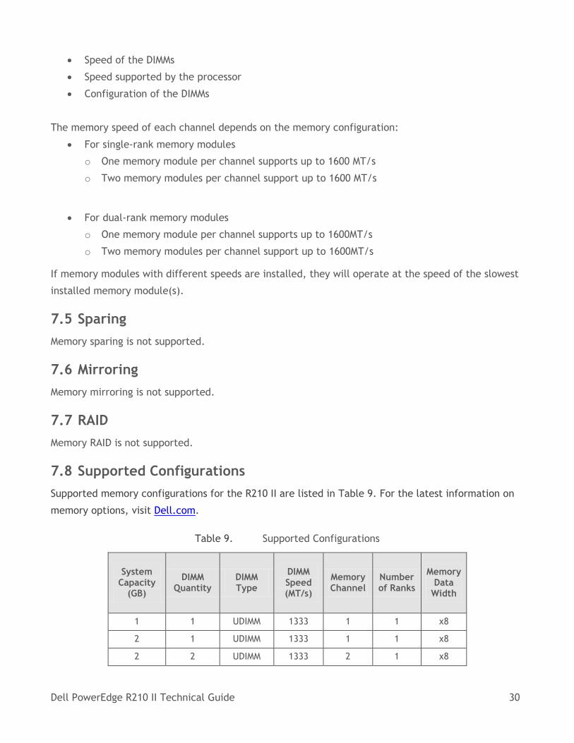
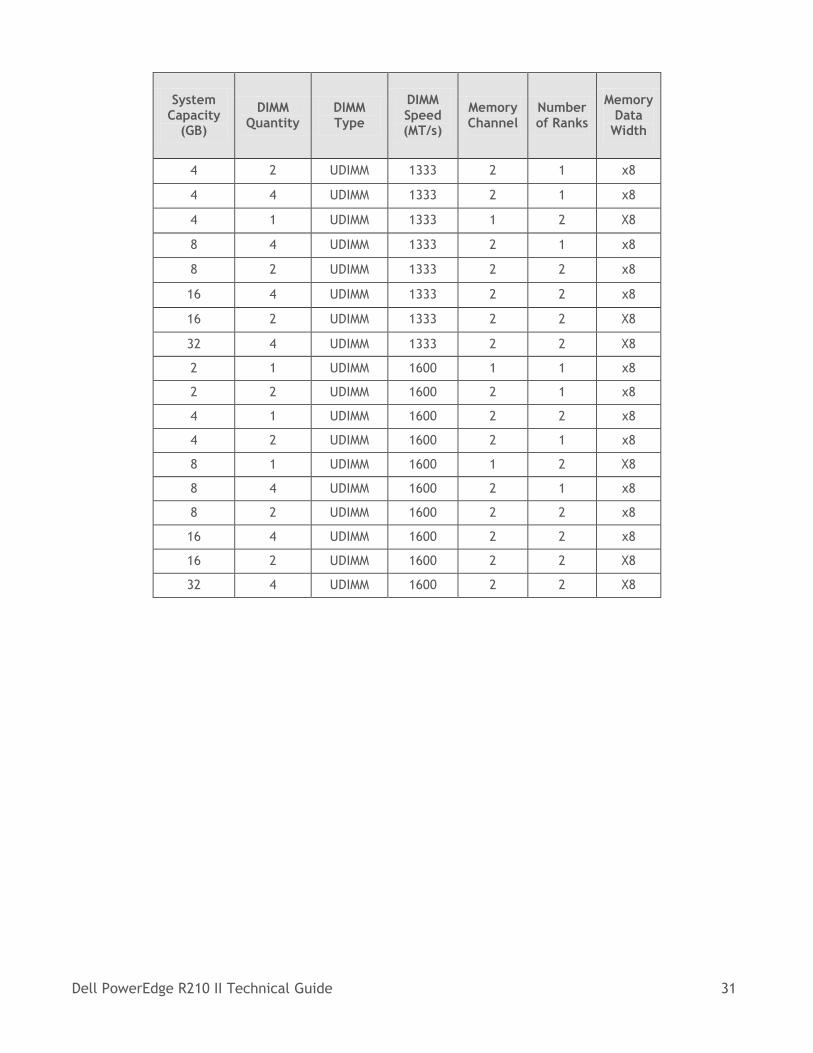
7.8 Supported Configurations
Supported memory configurations for the R210 II are listed in Table 9. For the latest information on
memory options, visit Dell.com.
Table 9. Supported Configurations
System Capacity
(GB)
DIMM Quantity
DIMM Type
DIMM Speed (MT/s)
Memory Channel
Number of Ranks
Memory Data
Width
1 1 UDIMM 1333 1 1 x8
2 1 UDIMM 1333 1 1 x8
2 2 UDIMM 1333 2 1 x8
Dell PowerEdge R210 II Technical Guide 31
System Capacity
(GB)
DIMM Quantity
DIMM Type
DIMM Speed (MT/s)
Memory Channel
Number of Ranks
Memory Data
Width
4 2 UDIMM 1333 2 1 x8
4 4 UDIMM 1333 2 1 x8
4 1 UDIMM 1333 1 2 X8
8 4 UDIMM 1333 2 1 x8
8 2 UDIMM 1333 2 2 x8
16 4 UDIMM 1333 2 2 x8
16 2 UDIMM 1333 2 2 X8
32 4 UDIMM 1333 2 2 X8
2 1 UDIMM 1600 1 1 x8
2 2 UDIMM 1600 2 1 x8
4 1 UDIMM 1600 2 2 x8
4 2 UDIMM 1600 2 1 x8
8 1 UDIMM 1600 1 2 X8
8 4 UDIMM 1600 2 1 x8
8 2 UDIMM 1600 2 2 x8
16 4 UDIMM 1600 2 2 x8
16 2 UDIMM 1600 2 2 X8
32 4 UDIMM 1600 2 2 X8
Dell PowerEdge R210 II Technical Guide 32
8 Chipset
8.1 Overview
The PowerEdge R210 II planar incorporates the Intel C200 Series PCH chipset. The features listed
below are part of the chipset.
8.2 Direct Media Interface
Direct Media Interface (DMI) is the chip-to-chip connection between the processor and C200 series
chipset. This high-speed interface integrates advanced priority-based servicing allowing for
concurrent traffic and true isochronous transfer capabilities. Base functionality is completely
software-transparent, permitting current and legacy software to operate normally.
8.3 PCI Express Interface
The C200 series provides up to 8 PCI Express root ports. Each root port supports 5GT/s bandwidth.
PCI Express Root Ports 1-4 can be statically configured as four x1 ports or ganged together to form
one x4 port. Ports 5 and 6 can only be used as two x1 ports.
8.4 SATA Interface
The chipset has two integrated SATA host controllers that support independent DMA operation on up
to six port: 6 x 3Gb/s SATA. The SATA controller contains two modes of operation, a legacy mode
using I/O space and an AHCI mode using memory space. Software that uses legacy mode will not have
AHCI capabilities.
8.5 AHCI
The chipset provides hardware support for Advanced Host Controller Interface (AHCI), a new
programming interface for SATA host controllers. Platforms supporting AHCI may take advantage of
performance features such as no master/slave designation for SATA devices — each device is treated
as a master — and hardware-assisted native command queuing. AHCI also provides usability
enhancements such as Hot-Plug. AHCI requires appropriate software support (for example, an AHCI
driver) and for some features, hardware support in the SATA device or additional platform hardware.
8.6 PCI Interface
The C200 Series chipset PCI interface provides a 33 MHz, Revision 2.3 implementation. The chipset
integrates a PCI arbiter that supports up to four external PCI bus masters in addition to the internal
requests. This allows for combinations of up to 8 PCI down devices and PCI slots.
Dell PowerEdge R210 II Technical Guide 33
8.7 Low-Pin Count (LPC) Interface
The LPC bridge function of the PCH resides in PCI Device 31: Function 0. In addition to the LPC bridge
function, D31:F0 contains other functional units including DMA, Interrupt controllers, Timers, Power
Management, System Management, GPIO, and RTC.
8.8 Serial Peripheral Interface (SPI)
The chipset implements an SPI Interface as an alternative interface for the BIOS flash device. An SPI
flash device can be used as a replacement for the FWH, and is required to support Gigabit Ethernet,
Intel® Active Management Technology, and integrated Intel Quiet System Technology. The chipset
supports up to two SPI flash devices with speed up to 20 MHz, 33 MHz utilizing two chip select pins.
8.9 Compatibility Module
The DMA controller incorporates the logic of two 82C37 DMA controllers, with seven independently
programmable channels. Channels 0–3 are hardwired to 8-bit, count-by-byte transfers, and channels
5–7 are hardwired to 16-bit, count-by-word transfers. Any two of the seven DMA channels can be
programmed to support fast Type-F transfers. Channel 4 is reserved as a generic bus master request.
The chipset supports LPC DMA, which is similar to ISA DMA, through the DMA controller. LPC DMA is
handled through the use of the LDRQ# lines from peripherals and special encoding on LAD[3:0] from
the host. Single, Demand, Verify, and Increment modes are supported on the LPC interface.
The timer/counter block contains three counters that are equivalent in function to those found in
one 82C54 programmable interval timer. These three counters are combined to provide the system
timer function, and speaker tone. The 14.31818 MHz oscillator input provides the clock source for
these three counters.
The chipset provides an ISA-Compatible Programmable Interrupt Controller (PIC) that incorporates
the functionality of two, 82C59 interrupt controllers. The two interrupt controllers are cascaded so
that 14 external and two internal interrupts are possible. In addition, the chipset supports a serial
interrupt scheme.
All of the registers in these modules can be read and restored. This is required to save and restore
system state after power has been removed and restored to the platform.
8.10 Advanced Programmable Interrupt Controller (APIC)
In addition to the standard ISA compatible Programmable Interrupt Controller (PIC) described in the
previous section, the Ibex Peak incorporates the Advanced Programmable Interrupt Controller (APIC).
Dell PowerEdge R210 II Technical Guide 34
8.11 USB Interface
The C200 Series chipset contains up to two Enhanced Host Controller Interface (EHCI) host controllers
that support USB high-speed signaling. High-speed USB 2.0 allows data transfers up to 480 Mb/s
which is 40 times faster than full-speed USB. The chipset also contains up to seven Universal Host
Controller Interface (UHCI) controllers that support USB full-speed and low-speed signaling.
The chipset supports up to fourteen USB 2.0 ports. All fourteen ports are high-speed, full-speed, and
low-speed capable. The port-routing logic determines whether a USB port is controlled by one of the
UHCI or EHCI controllers.
8.12 Real-Time Clock (RTC)
The Real Time Clock (RTC) module provides a battery backed-up date and time keeping device with
two banks of static RAM with 128 bytes each, although the first bank has 114 bytes for general
purpose usage. Three interrupt features are available: time of day alarm with once a second to once
a month range, periodic rates of 122 μs to 500 ms, and end of update cycle notification. Seconds,
minutes, hours, days, day of week, month, and year are counted. Daylight savings compensation is no
longer supported. The hour is represented in twelve or twenty-four hour format, and data can be
represented in BCD or binary format. The design is functionally compatible with the Motorola
MS146818B. The time keeping comes from a 32.768 kHz oscillating source, which is divided to
achieve an update every second. The lower 14 bytes on the lower RAM block has very specific
functions. The first ten are for time and date information. The next four (0Ah to 0Dh) are registers,
which configure and report RTC functions.
8.13 GPIO
Various general purpose inputs and outputs are provided for custom system design. The number of
inputs and outputs varies depending on C200 series configuration.
8.14 Enhanced Power Management
The C200 series power management functions include enhanced clock control and various low-power
(suspend) states (for example, Suspend-to-RAM and Suspend-to-Disk). A hardware-based thermal
management circuit permits software-independent entrance to low-power states. The chipset
contains full support for the Advanced Configuration and Power Interface (ACPI) Specification,
Revision 3.0a.
8.15 System Management Features
In addition to Intel AMT, the C200 series chipset integrates several functions designed to manage the
system and lower the total cost of ownership (TCO) of the system. These system management
Dell PowerEdge R210 II Technical Guide 35
functions are designed to report errors, diagnose the system, and recover from system lockups
without the aid of an external microcontroller.
8.15.1 TCO Timer
The chipset’s integrated programmable TCO timer is used to detect system locks. The first expiration
of the timer generates an SMI# that the system can use to recover from a software lock. The second
expiration of the timer causes a system reset to recover from a hardware lock.
8.15.2 Processor Present Indicator
The chipset looks for the processor to fetch the first instruction after reset. If the processor does not
fetch the first instruction, the Ibex Peak will reboot the system.
8.15.3 Error Code Correction (ECC) Reporting
When detecting an ECC error, the host controller has the ability to send one of several messages to
the chipset. The host controller can instruct the chipset to generate an SMI#, NMI, SERR#, or TCO
interrupt.
8.15.4 Function Disable
The chipset provides the ability to disable the following integrated functions: LAN, USB, LPC, Intel
HD Audio, SATA, PCI Express or SMBus. Once disabled, these functions no longer decode I/O, memory,
or PCI configuration space. Also, no interrupts or power management events are generated from the
disabled functions.
8.15.5 Intruder Detect
The chipset provides an input signal (INTRUDER#) that can be attached to a switch that is activated
when the system case is opened. The chipset can be programmed to generate an SMI# or TCO
interrupt due to an active INTRUDER# signal.
8.16 System Management Bus (SMBus 2.0)
The chipset contains an SMBus Host interface that allows the processor to communicate with SMBus
slaves. This interface is compatible with most I2C devices. Special I2C commands are implemented.
The chipset’s SMBus host controller provides a mechanism for the processor to initiate
communications with SMBus peripherals (slaves). Also, the chipset supports slave functionality,
including the Host Notify protocol. Hence, the host controller supports eight command protocols of
the SMBus interface.
Dell PowerEdge R210 II Technical Guide 36
The chipset’s SMBus also implements hardware-based Packet Error Checking for data robustness and
the Address Resolution Protocol (ARP) to dynamically provide address to all SMBus devices.
8.17 Intel Virtualization Technology for Directed I/O
The chipset provides hardware support for implementation of Intel Virtualization Technology with
Directed I/O (Intel VT-d). Intel VT-d Technology consists of technology components that support the
virtualization of platforms based on Intel Architecture Processors. Intel VT-d Technology enables
multiple operating systems and applications to run in independent partitions. A partition behaves like
a virtual machine (VM) and provides isolation and protection across partitions. Each partition is
allocated its own subset of host physical memory.
Dell PowerEdge R210 II Technical Guide 37
9 BIOS
9.1 Overview
The R210 II BIOS is based on the Insyde® BIOS core which supports the following features:
Simultaneous Multi-Threading (SMT) support
PCI 2.3 compliant
Plug and Play 1.0a compliant
MP (Multiprocessor) 1.4 compliant
Ability to boot from hard drive, optical drive, iSCSI drive, USB key, and SD card
ACPI 2.0 support (S0, OS-S4, S5 States)
PXE and WOL support for on-board NICs
SETUP access through <F2> key at end of POST
USB 2.0 (USB boot code is 1.1 compliant)
F1/F2 error logging in CMOS
Virtual KVM, CD, and floppy support
iDRAC supported
Unified Server Configurator (UEFI 2.1) support
Power management support including DBS, Power Inventory and multiple Power Profiles:
o Maximum Performance
o OS Control (DBS)
o Custom
SMBIOS 2.5
PCI-to-PCI bridge 1.0 compliant
Dell Server Assistant 7.0 support
System Service support
Onboard PCI video BIOS support
SATA-enabled for CD-ROM and hard drives
PCI FW 3.0 compliant
Selectable Boot support
El Torito CD-ROM Boot 1.0
Remote BIOS Update support
Remote Configuration Interface (RCI) support
Console redirection through COM1
PXE support based on Preboot Execution Environment Specification v2.1
2-byte ID support
ePPID support in flash
Dell PowerEdge R210 II Technical Guide 38
Memory remapping support
DDR3 UDIMM memory support
UEFI shell Support
AC recovery staggering Power-Up
DIMM mismatch checking
VT-d
The PowerEdge R210 II BIOS does not support the following:
BIOS language localization
BIOS recovery after bad flash
RIB Support
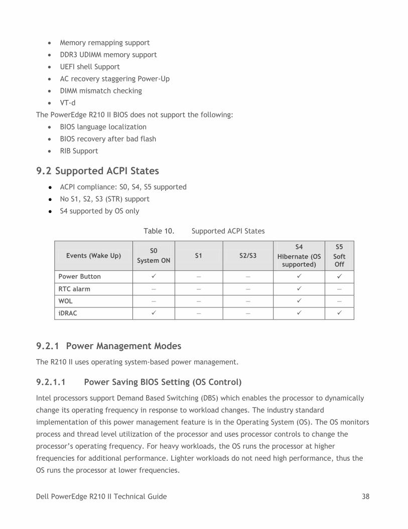
9.2 Supported ACPI States
● ACPI compliance: S0, S4, S5 supported
● No S1, S2, S3 (STR) support
● S4 supported by OS only
Table 10. Supported ACPI States
Events (Wake Up) S0
System ON S1 S2/S3
S4
Hibernate (OS supported)
S5
Soft Off
Power Button — —
RTC alarm — — — —
WOL — — — —
iDRAC — —
9.2.1 Power Management Modes
The R210 II uses operating system-based power management.
9.2.1.1 Power Saving BIOS Setting (OS Control)
Intel processors support Demand Based Switching (DBS) which enables the processor to dynamically
change its operating frequency in response to workload changes. The industry standard
implementation of this power management feature is in the Operating System (OS). The OS monitors
process and thread level utilization of the processor and uses processor controls to change the
processor’s operating frequency. For heavy workloads, the OS runs the processor at higher
frequencies for additional performance. Lighter workloads do not need high performance, thus the
OS runs the processor at lower frequencies.
Dell PowerEdge R210 II Technical Guide 39
9.2.1.2 Maximum Performance
The Maximum Performance Mode disables power management. In this mode, the processor frequency
is statically set to the highest supported frequency.
The power management features are implemented through two categories: fixed or generic. Fixed
features use bits defined in the ACPI specification for specific capabilities. The fixed feature bits
give the OS complete control over the power management of a device since the location of the bits is
given to the OS in the FACP table. Thus, a driver can directly access bits to control a device’s power
management. Generic features have defined enable and status bits, but the functionality is not fully
visible to the OS. Dell provides ASL code to handle the details of generic features, allowing the OS to
intelligently communicate with system-specific hardware.
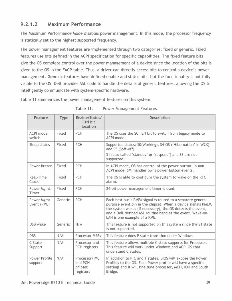
Table 11 summarizes the power management features on this system:
Table 11. Power Management Features
Feature Type Enable/Status/ Ctrl bit location
Description
ACPI mode switch
Fixed PCH The OS uses the SCI_EN bit to switch from legacy mode to ACPI mode.
Sleep states Fixed PCH Supported states: S0(Working), S4-OS (‘Hibernation’ in W2K), and S5 (Soft-off).
S1 (also called ‘standby’ or ‘suspend’) and S3 are not supported.
Power Button Fixed PCH In ACPI mode, OS has control of the power button. In non-ACPI mode, SMI handler owns power button events.
Real-Time Clock
Fixed PCH The OS is able to configure the system to wake on the RTC alarm.
Power Mgmt. Timer
Fixed PCH 24-bit power management timer is used.
Power Mgmt. Event (PME)
Generic PCH Each host bus’s PME# signal is routed to a separate general-purpose event pin in the chipset. When a device signals PME#, the system wakes (if necessary), the OS detects the event, and a Dell-defined ASL routine handles the event. Wake-on-LAN is one example of a PME.
USB wake Generic N/A This feature is not supported on this system since the S1 state is not supported.
DBS N/A Processor MSRs This feature does P state transition under Windows
C State Support
N/A Processor and PCH registers
This feature allows multiple C state supports for Processor. This feature will work under Windows and ACPI OS that understand C states.
Power Profile support
N/A Processor/IMC and PCH chipset registers
In addition to P,C and T states, BIOS will expose the Power Profiles to the OS. Each Power profile will have a specific settings and it will fine tune processor, MCH, IOH and South Bridge.
Dell PowerEdge R210 II Technical Guide 40
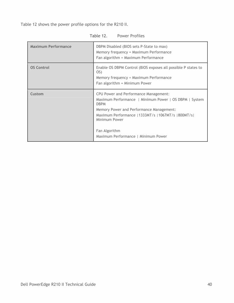
Table 12 shows the power profile options for the R210 II.
Table 12. Power Profiles
Maximum Performance DBPM Disabled (BIOS sets P-State to max)
Memory frequency = Maximum Performance
Fan algorithm = Maximum Performance
OS Control Enable OS DBPM Control (BIOS exposes all possible P states to OS)
Memory frequency = Maximum Performance
Fan algorithm = Minimum Power
Custom CPU Power and Performance Management:
Maximum Performance | Minimum Power | OS DBPM | System DBPM
Memory Power and Performance Management:
Maximum Performance |1333MT/s |1067MT/s |800MT/s| Minimum Power
Fan Algorithm
Maximum Performance | Minimum Power
Dell PowerEdge R210 II Technical Guide 41
10 Embedded NICs/LAN on Motherboard (LOM)
10.1 Overview
The PowerEdge R210 II includes a Broadcom® 5716C chip embedded on the motherboard. The 5716
chip is connected to the IOH via a PCI Express x4 gen2 link. The 5716 chip provides two 1x Gigabit
Ethernet ports with two RJ-45 connectors on the rear of the system. Other details include:
The firmware for the LOM chip resides in a flash part
The R210 II supports Wake-On-LAN (WOL) from either port
10.2 Features
The Broadcom® 5716C controller-based LOM supports multiple functions over a unified fabric to help
manage Ethernet, iSCSI and remote management traffic on each port simultaneously. The LOM
provides dual 10/100/1000 Gigabit Ethernet functions, an IEEE 802.3-compliant media access
controller (MAC), and a UTP copper physical layer transceiver solution for high-performance network
applications. The LOM also supports the following functions:
Multiple speed support with dual 10/100/1000-Mbps Ethernet MACs, including half-duplex and
full-duplex capability and a dual 10/100/1000 copper PHY
PCIe compliance with an x4 PCI Express v2.0- and v1.1-compliant bus interface
Diagnostics:
o Link quality indicator LED
o Link speed indicator LED
o Broadcom remote cable management and diagnostics software (Broadcom Advanced
Control Suite [BACS])
o LOM continually monitors various channel conditions
Power management options
Teaming using Broadcom software:
o Support for virtual LANs (VLANs):
Split your physical LAN into logical parts
Create logical segmentation of workgroups
Enforce security policies for each logical segment
o Group multiple network adapters together into teams, providing network load
balancing and fault tolerance functionality
Support for Pre-boot Execution Environment (PXE), iSCSI boot, and Bootstrap Protocol (BootP)
Support for Network Controller Sideband Interface (NC-SI)
IPv4 and IPv6 checksum offload
Dell PowerEdge R210 II Technical Guide 42
IPv4 and IPv6 large send offload
Jumbo MTU
LSO and jumbo frames
WOL capabilities
Virtualization functionality
Use of multiple queues
Dell PowerEdge R210 II Technical Guide 43
11 PCI Slots
11.1 Overview
The PowerEdge R210 II planar provides one riser card which provides one x16 Gen2 PCI Express
expansion slot:
Slot supports full-height half-length cards connected to the IOH
Support for 25W maximum power
System does not support hot-plugging or hot-removal of PCIe cards
For more information on installing expansion cards and expansion-card priority, see the Expansion
Cards and Expansion-Card Risers section in the Installing System Components chapter of the Dell
PowerEdge R210 II Owner’s Manual on Dell.com/Support/Manuals.
11.2 Quantities and Priorities
Refer to the Expansion Cards and Expansion-Card Risers section in the Installing System Components
chapter of the Dell PowerEdge R210 II Owner’s Manual on Dell.com/Support/Manuals.
11.3 PCI Card Dimensions
Refer to the Expansion Cards and Expansion-Card Risers section in the Installing System Components
chapter of the Dell PowerEdge R210 II Owner’s Manual on Dell.com/Support/Manuals.
Dell PowerEdge R210 II Technical Guide 44
12 Storage
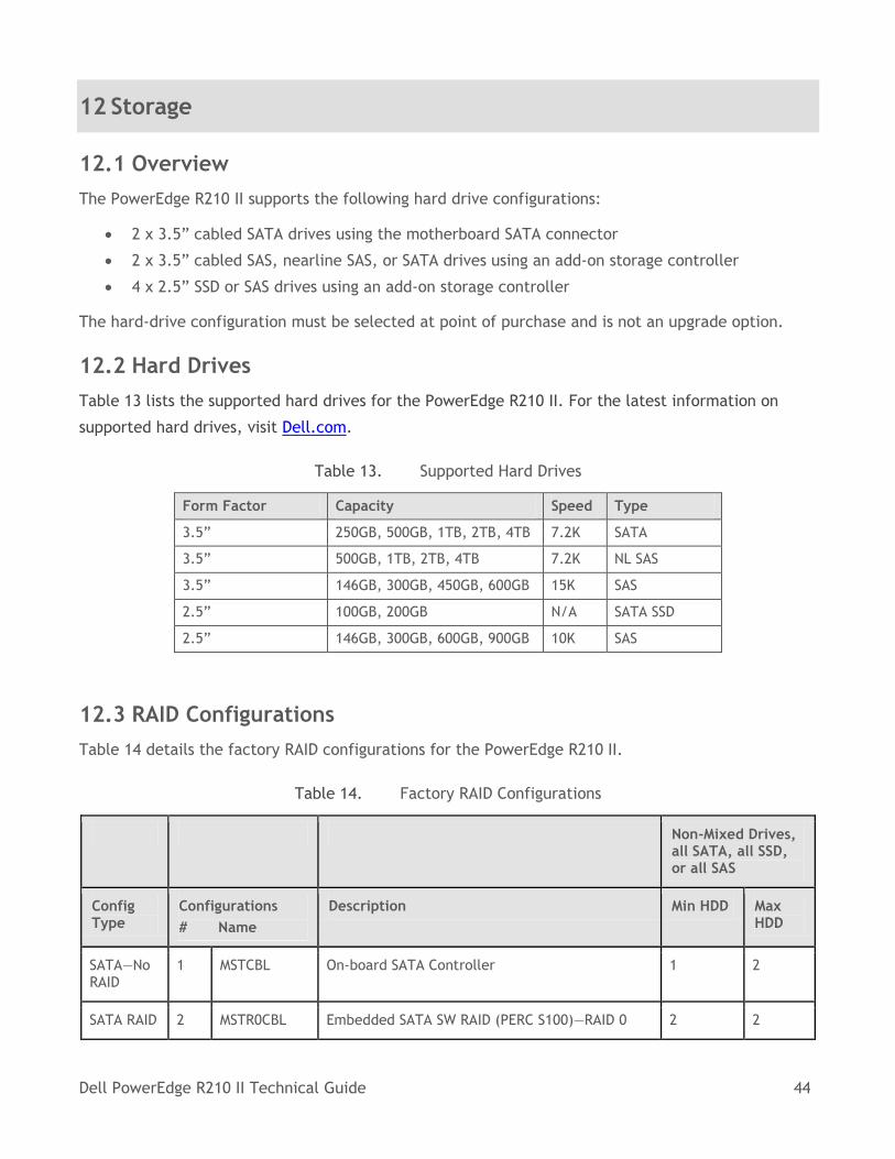
12.1 Overview
The PowerEdge R210 II supports the following hard drive configurations:
2 x 3.5” cabled SATA drives using the motherboard SATA connector
2 x 3.5” cabled SAS, nearline SAS, or SATA drives using an add-on storage controller
4 x 2.5” SSD or SAS drives using an add-on storage controller
The hard-drive configuration must be selected at point of purchase and is not an upgrade option.
12.2 Hard Drives
Table 13 lists the supported hard drives for the PowerEdge R210 II. For the latest information on
supported hard drives, visit Dell.com.
Table 13. Supported Hard Drives
Form Factor Capacity Speed Type
3.5” 250GB, 500GB, 1TB, 2TB, 4TB 7.2K SATA
3.5” 500GB, 1TB, 2TB, 4TB 7.2K NL SAS
3.5” 146GB, 300GB, 450GB, 600GB 15K SAS
2.5” 100GB, 200GB N/A SATA SSD
2.5” 146GB, 300GB, 600GB, 900GB 10K SAS
12.3 RAID Configurations
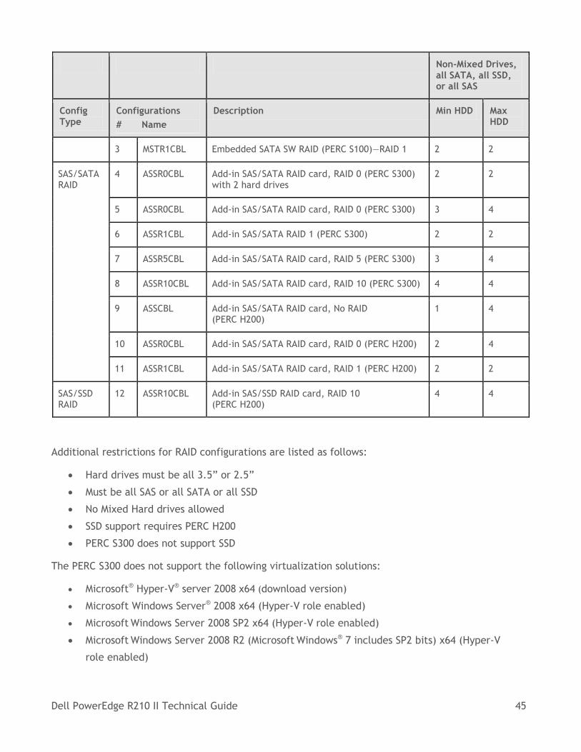
Table 14 details the factory RAID configurations for the PowerEdge R210 II.
Table 14. Factory RAID Configurations
Non-Mixed Drives, all SATA, all SSD, or all SAS
Config Type
Configurations
# Name
Description Min HDD Max HDD
SATA—No RAID
1 MSTCBL On-board SATA Controller 1 2
SATA RAID 2 MSTR0CBL Embedded SATA SW RAID (PERC S100)—RAID 0 2 2
Dell PowerEdge R210 II Technical Guide 45
Non-Mixed Drives, all SATA, all SSD, or all SAS
Config Type
Configurations
# Name
Description Min HDD Max HDD
3 MSTR1CBL Embedded SATA SW RAID (PERC S100)—RAID 1 2 2
SAS/SATA RAID
4 ASSR0CBL Add-in SAS/SATA RAID card, RAID 0 (PERC S300) with 2 hard drives
2 2
5 ASSR0CBL Add-in SAS/SATA RAID card, RAID 0 (PERC S300) 3 4
6 ASSR1CBL Add-in SAS/SATA RAID 1 (PERC S300) 2 2
7 ASSR5CBL Add-in SAS/SATA RAID card, RAID 5 (PERC S300) 3 4
8 ASSR10CBL Add-in SAS/SATA RAID card, RAID 10 (PERC S300) 4 4
9 ASSCBL Add-in SAS/SATA RAID card, No RAID (PERC H200)
1 4
10 ASSR0CBL Add-in SAS/SATA RAID card, RAID 0 (PERC H200) 2 4
11 ASSR1CBL Add-in SAS/SATA RAID card, RAID 1 (PERC H200) 2 2
SAS/SSD RAID
12 ASSR10CBL Add-in SAS/SSD RAID card, RAID 10 (PERC H200)
4 4
Additional restrictions for RAID configurations are listed as follows:
Hard drives must be all 3.5” or 2.5”
Must be all SAS or all SATA or all SSD
No Mixed Hard drives allowed
SSD support requires PERC H200
PERC S300 does not support SSD
The PERC S300 does not support the following virtualization solutions:
Microsoft® Hyper-V® server 2008 x64 (download version)
Microsoft Windows Server® 2008 x64 (Hyper-V role enabled)
Microsoft Windows Server 2008 SP2 x64 (Hyper-V role enabled)
Microsoft Windows Server 2008 R2 (Microsoft Windows® 7 includes SP2 bits) x64 (Hyper-V
role enabled)
Dell PowerEdge R210 II Technical Guide 46
The PERC S300 does not support Linux® operating systems or VMware® virtualization software.
12.4 Optical Drives
The R210 II supports one SATA interface DVD-ROM or DVD+/-RW.
12.5 Tape Drives
External tape drives and tape libraries are supported. No internal tape drive support is available.
For more information on supported tape drives and tape libraries, see Dell.com/Storage.
Dell PowerEdge R210 II Technical Guide 47
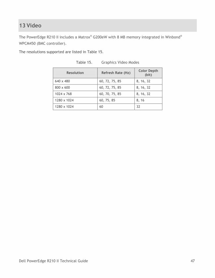
13 Video
The PowerEdge R210 II includes a Matrox® G200eW with 8 MB memory integrated in Winbond®
WPCM450 (BMC controller).
The resolutions supported are listed in Table 15.
Table 15. Graphics Video Modes
Resolution Refresh Rate (Hz) Color Depth
(bit)
640 x 480 60, 72, 75, 85 8, 16, 32
800 x 600 60, 72, 75, 85 8, 16, 32
1024 x 768 60, 70, 75, 85 8, 16, 32
1280 x 1024 60, 75, 85 8, 16
1280 x 1024 60 32
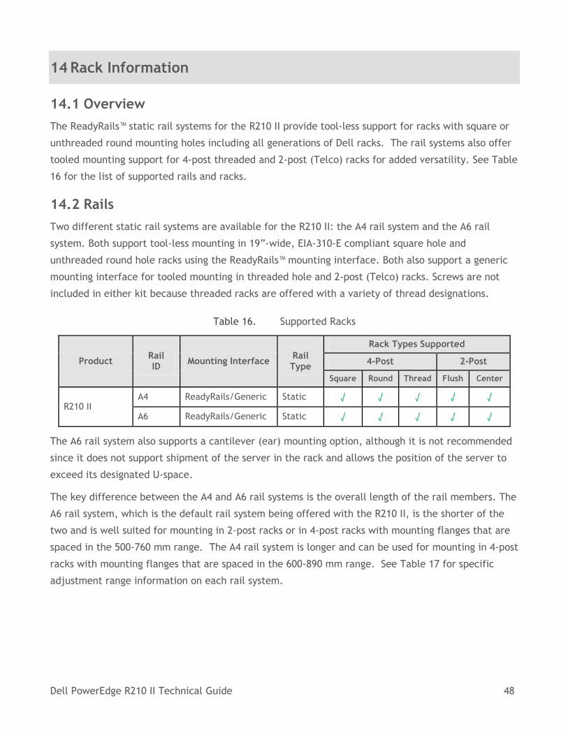
Dell PowerEdge R210 II Technical Guide 48
14 Rack Information
14.1 Overview
The ReadyRails™ static rail systems for the R210 II provide tool-less support for racks with square or
unthreaded round mounting holes including all generations of Dell racks. The rail systems also offer
tooled mounting support for 4-post threaded and 2-post (Telco) racks for added versatility. See Table
16 for the list of supported rails and racks.
14.2 Rails
Two different static rail systems are available for the R210 II: the A4 rail system and the A6 rail
system. Both support tool-less mounting in 19”-wide, EIA-310-E compliant square hole and
unthreaded round hole racks using the ReadyRails™ mounting interface. Both also support a generic
mounting interface for tooled mounting in threaded hole and 2-post (Telco) racks. Screws are not
included in either kit because threaded racks are offered with a variety of thread designations.
Table 16. Supported Racks
Product Rail ID
Mounting Interface Rail Type
Rack Types Supported
4-Post 2-Post
Square Round Thread Flush Center
R210 II A4 ReadyRails/Generic Static √ √ √ √ √
A6 ReadyRails/Generic Static √ √ √ √ √
The A6 rail system also supports a cantilever (ear) mounting option, although it is not recommended
since it does not support shipment of the server in the rack and allows the position of the server to
exceed its designated U-space.
The key difference between the A4 and A6 rail systems is the overall length of the rail members. The
A6 rail system, which is the default rail system being offered with the R210 II, is the shorter of the
two and is well suited for mounting in 2-post racks or in 4-post racks with mounting flanges that are
spaced in the 500-760 mm range. The A4 rail system is longer and can be used for mounting in 4-post
racks with mounting flanges that are spaced in the 600-890 mm range. See Table 17 for specific
adjustment range information on each rail system.
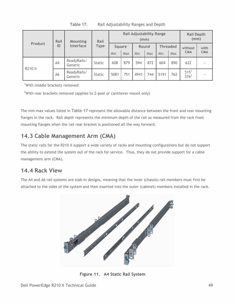
Dell PowerEdge R210 II Technical Guide 49
Table 17. Rail Adjustability Ranges and Depth
Product Rail ID
Mounting Interface
Rail Type
Rail Adjustability Range
(mm)
Rail Depth (mm)
Square Round Threaded without CMA
with CMA Min Max Min Max Min Max
R210 II
A4 ReadyRails/ Generic
Static 608 879 594 872 604 890 622 —
A6 ReadyRails/ Generic
Static 5081 751 4941 744 5191 762 5151 3762
—
1With middle brackets removed
2With rear brackets removed (applies to 2-post or cantilever mount only)
The min-max values listed in Table 17 represent the allowable distance between the front and rear mounting
flanges in the rack. Rail depth represents the minimum depth of the rail as measured from the rack front
mounting flanges when the rail rear bracket is positioned all the way forward.
14.3 Cable Management Arm (CMA)
The static rails for the R210 II support a wide variety of racks and mounting configurations but do not support
the ability to extend the system out of the rack for service. Thus, they do not provide support for a cable
management arm (CMA).
14.4 Rack View
The A4 and A6 rail systems are stab-in designs, meaning that the inner (chassis) rail members must first be
attached to the sides of the system and then inserted into the outer (cabinet) members installed in the rack.
Figure 11. A4 Static Rail System
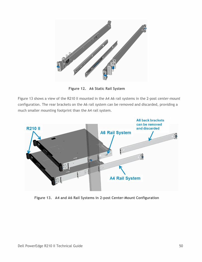
Dell PowerEdge R210 II Technical Guide 50
Figure 12. A6 Static Rail System
Figure 13 shows a view of the R210 II mounted in the A4 A6 rail systems in the 2-post center-mount
configuration. The rear brackets on the A6 rail system can be removed and discarded, providing a
much smaller mounting footprint than the A4 rail system.
Figure 13. A4 and A6 Rail Systems in 2-post Center-Mount Configuration
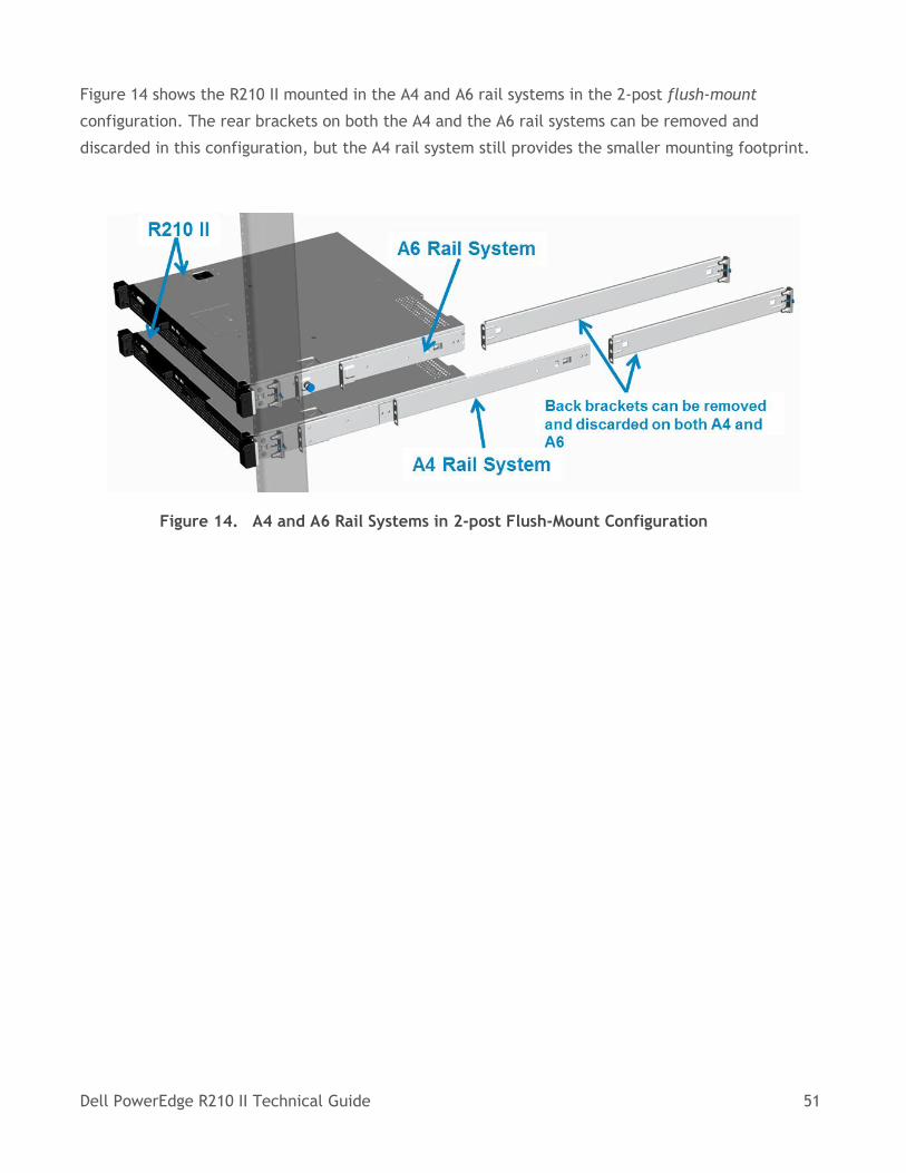
Dell PowerEdge R210 II Technical Guide 51
Figure 14 shows the R210 II mounted in the A4 and A6 rail systems in the 2-post flush-mount
configuration. The rear brackets on both the A4 and the A6 rail systems can be removed and
discarded in this configuration, but the A4 rail system still provides the smaller mounting footprint.
Figure 14. A4 and A6 Rail Systems in 2-post Flush-Mount Configuration
Dell PowerEdge R210 II Technical Guide 52
15 Operating Systems
For detailed information, see the following:
Operating System Support Matrix for Dell PowerEdge Systems on Dell.com
Dell PowerEdge R210 II Getting Started Guide on Dell.com/Support/Manuals
Dell PowerEdge R210 II Technical Guide 53
16 Systems Management
16.1 Overview
Dell delivers open, comprehensive, and integrated solutions that help you reduce the complexity of
managing disparate IT assets. Combining Dell PowerEdge Servers with a wide selection of Dell
developed systems management solutions gives you choice and flexibility, so you can simplify and
save in IT environments of any size. To help you meet your server management demands, Dell offers
Dell OpenManage™ systems management solutions for:
Deployment of one or many servers from a single console
Monitoring of server and storage health and maintenance
Update of system, operating system, and application software
Dell offers IT management solutions for organizations of all sizes—priced and sized appropriately and
supported comprehensively.
16.2 Server Management
A Dell Systems Management and Documentation DVD are included with the product. ISO images are
also available. A brief description of available content:
• Dell Systems Build and Update Utility (SBUU): Dell Systems Build and Update Utility assists in
OS install and pre-OS hardware configuration and updates.
• Server Update Utility (SUU): This DVD has an inventory tool for managing updates to
firmware, BIOS, and drivers for either Linux or Windows varieties.
• OpenManage Server Administrator (OMSA): The OpenManage Server Administrator tool
provides a comprehensive, one-to-one (one console to one server) systems management
solution, designed for system administrators to manage systems locally and remotely over a
network. OMSA allows system administrators to focus on managing their entire network by
providing comprehensive one-to-one systems management.
• Active Directory Snap-in Utility: The Active Directory Snap-in Utility provides an extension
snap-in to the Microsoft Active Directory. This allows you to manage Dell specific Active
Directory objects. The Dell-specific schema class definitions and their installation are also
included on the DVD.
• Dell Systems Service Diagnostics Tools: Dell Systems Service and Diagnostics tools deliver the
latest Dell optimized drivers, utilities, and operating system-based diagnostics that you can
use to update your system.
• eDocs: The section includes PDF files for PowerEdge systems, storage peripherals, and Dell
OpenManage™ software.
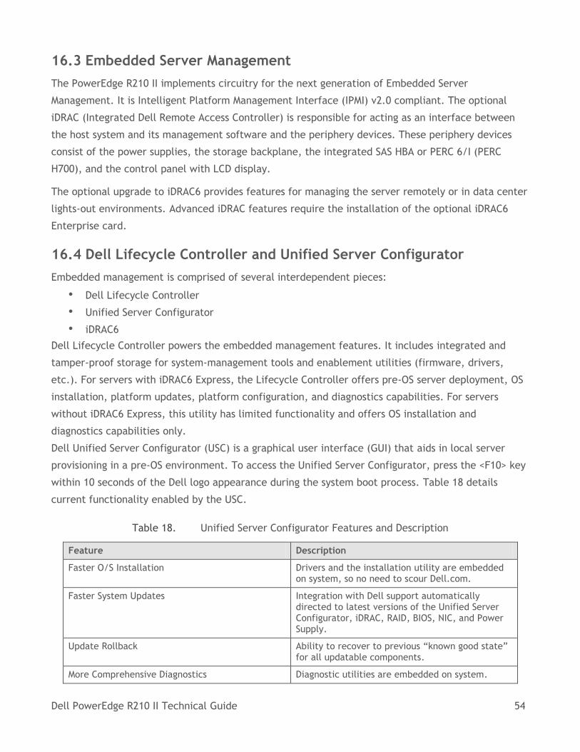
Dell PowerEdge R210 II Technical Guide 54
16.3 Embedded Server Management
The PowerEdge R210 II implements circuitry for the next generation of Embedded Server
Management. It is Intelligent Platform Management Interface (IPMI) v2.0 compliant. The optional
iDRAC (Integrated Dell Remote Access Controller) is responsible for acting as an interface between
the host system and its management software and the periphery devices. These periphery devices
consist of the power supplies, the storage backplane, the integrated SAS HBA or PERC 6/I (PERC
H700), and the control panel with LCD display.
The optional upgrade to iDRAC6 provides features for managing the server remotely or in data center
lights-out environments. Advanced iDRAC features require the installation of the optional iDRAC6
Enterprise card.
16.4 Dell Lifecycle Controller and Unified Server Configurator
Embedded management is comprised of several interdependent pieces:
• Dell Lifecycle Controller
• Unified Server Configurator
• iDRAC6
Dell Lifecycle Controller powers the embedded management features. It includes integrated and
tamper-proof storage for system-management tools and enablement utilities (firmware, drivers,
etc.). For servers with iDRAC6 Express, the Lifecycle Controller offers pre-OS server deployment, OS
installation, platform updates, platform configuration, and diagnostics capabilities. For servers
without iDRAC6 Express, this utility has limited functionality and offers OS installation and
diagnostics capabilities only.
Dell Unified Server Configurator (USC) is a graphical user interface (GUI) that aids in local server
provisioning in a pre-OS environment. To access the Unified Server Configurator, press the <F10> key
within 10 seconds of the Dell logo appearance during the system boot process. Table 18 details
current functionality enabled by the USC.
Table 18. Unified Server Configurator Features and Description
Feature Description
Faster O/S Installation Drivers and the installation utility are embedded on system, so no need to scour Dell.com.
Faster System Updates Integration with Dell support automatically directed to latest versions of the Unified Server Configurator, iDRAC, RAID, BIOS, NIC, and Power Supply.
Update Rollback Ability to recover to previous “known good state” for all updatable components.
More Comprehensive Diagnostics Diagnostic utilities are embedded on system.
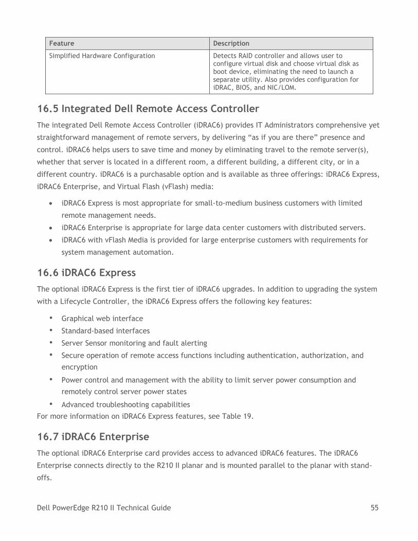
Dell PowerEdge R210 II Technical Guide 55
Feature Description
Simplified Hardware Configuration Detects RAID controller and allows user to configure virtual disk and choose virtual disk as boot device, eliminating the need to launch a separate utility. Also provides configuration for iDRAC, BIOS, and NIC/LOM.
16.5 Integrated Dell Remote Access Controller
The integrated Dell Remote Access Controller (iDRAC6) provides IT Administrators comprehensive yet
straightforward management of remote servers, by delivering “as if you are there” presence and
control. iDRAC6 helps users to save time and money by eliminating travel to the remote server(s),
whether that server is located in a different room, a different building, a different city, or in a
different country. iDRAC6 is a purchasable option and is available as three offerings: iDRAC6 Express,
iDRAC6 Enterprise, and Virtual Flash (vFlash) media:
iDRAC6 Express is most appropriate for small-to-medium business customers with limited
remote management needs.
iDRAC6 Enterprise is appropriate for large data center customers with distributed servers.
iDRAC6 with vFlash Media is provided for large enterprise customers with requirements for
system management automation.
16.6 iDRAC6 Express
The optional iDRAC6 Express is the first tier of iDRAC6 upgrades. In addition to upgrading the system
with a Lifecycle Controller, the iDRAC6 Express offers the following key features:
• Graphical web interface
• Standard-based interfaces
• Server Sensor monitoring and fault alerting
• Secure operation of remote access functions including authentication, authorization, and
encryption
• Power control and management with the ability to limit server power consumption and
remotely control server power states
• Advanced troubleshooting capabilities
For more information on iDRAC6 Express features, see Table 19.
16.7 iDRAC6 Enterprise
The optional iDRAC6 Enterprise card provides access to advanced iDRAC6 features. The iDRAC6
Enterprise connects directly to the R210 II planar and is mounted parallel to the planar with stand-
offs.
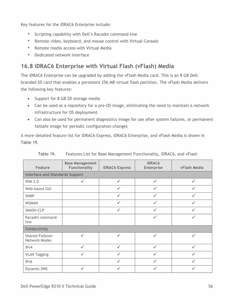
Dell PowerEdge R210 II Technical Guide 56
Key features for the iDRAC6 Enterprise include:
• Scripting capability with Dell’s Racadm command-line
• Remote video, keyboard, and mouse control with Virtual Console
• Remote media access with Virtual Media
• Dedicated network interface
16.8 iDRAC6 Enterprise with Virtual Flash (vFlash) Media
The iDRAC6 Enterprise can be upgraded by adding the vFlash Media card. This is an 8 GB Dell-
branded SD card that enables a persistent 256 MB virtual flash partition. The vFlash Media delivers
the following key features:
Support for 8 GB SD storage media
Can be used as a repository for a pre-OS image, eliminating the need to maintain a network
infrastructure for OS deployment
Can also be used for permanent diagnostics image for use after system failures, or permanent
failsafe image for periodic configuration changes
A more detailed feature list for iDRAC6 Express, iDRAC6 Enterprise, and vFlash Media is shown in
Table 19.
Table 19. Features List for Base Management Functionality, iDRAC6, and vFlash
Feature Base Management
Functionality iDRAC6 Express iDRAC6
Enterprise vFlash Media
Interface and Standards Support
IPMI 2.0
Web-based GUI
SNMP
WSMAN
SMASH-CLP
Racadm command-line
Conductivity
Shared/Failover Network Modes
IPv4
VLAN Tagging
IPv6
Dynamic DNS
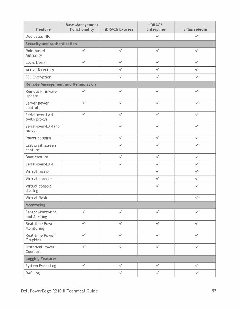
Dell PowerEdge R210 II Technical Guide 57
Feature Base Management
Functionality iDRAC6 Express iDRAC6
Enterprise vFlash Media
Dedicated NIC
Security and Authentication
Role-based Authority
Local Users
Active Directory
SSL Encryption
Remote Management and Remediation
Remote Firmware Update
Server power control
Serial-over-LAN (with proxy)
Serial-over-LAN (no proxy)
Power capping
Last crash screen capture
Boot capture
Serial-over-LAN
Virtual media
Virtual console
Virtual console sharing
Virtual flash
Monitoring
Sensor Monitoring and Alerting
Real-time Power Monitoring
Real-time Power Graphing
Historical Power Counters
Logging Features
System Event Log
RAC Log
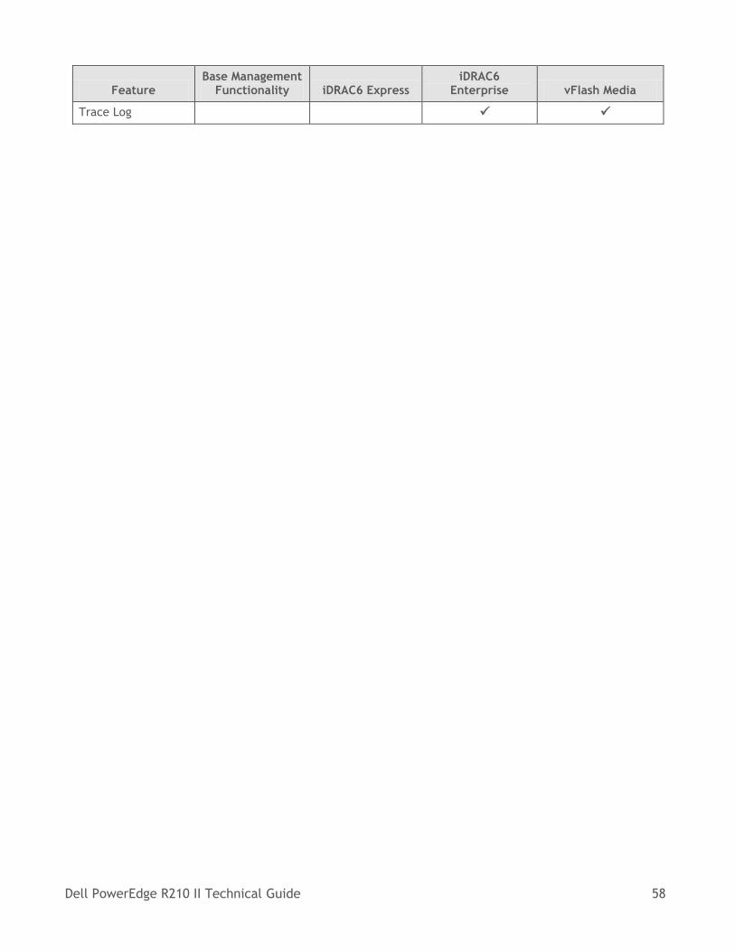
Dell PowerEdge R210 II Technical Guide 58
Feature Base Management
Functionality iDRAC6 Express iDRAC6
Enterprise vFlash Media
Trace Log
Dell PowerEdge R210 II Technical Guide 59
17 Peripherals
The PowerEdge R210 II supports the following USB devices:
DVD (bootable; requires two USB ports)
USB key (bootable)
Keyboard (only one USB keyboard is supported)
Mouse (only one USB mouse is supported)
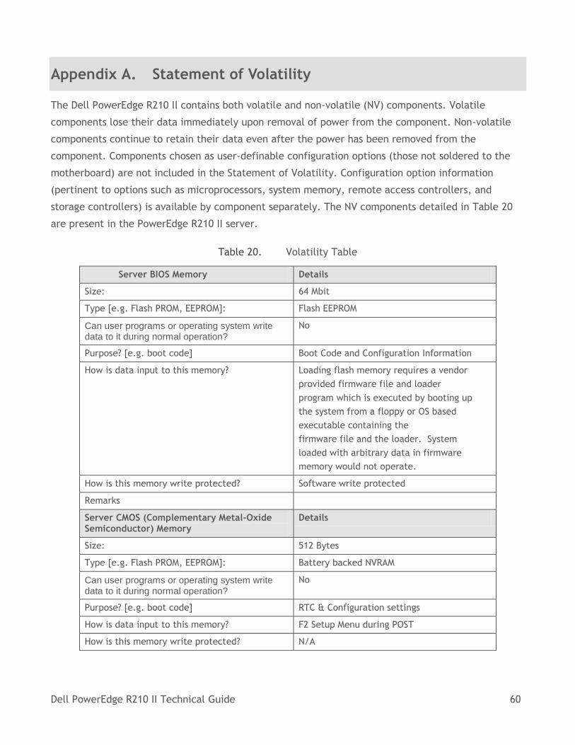
Dell PowerEdge R210 II Technical Guide 60
Appendix A. Statement of Volatility
The Dell PowerEdge R210 II contains both volatile and non-volatile (NV) components. Volatile
components lose their data immediately upon removal of power from the component. Non-volatile
components continue to retain their data even after the power has been removed from the
component. Components chosen as user-definable configuration options (those not soldered to the
motherboard) are not included in the Statement of Volatility. Configuration option information
(pertinent to options such as microprocessors, system memory, remote access controllers, and
storage controllers) is available by component separately. The NV components detailed in Table 20
are present in the PowerEdge R210 II server.
Table 20. Volatility Table
Server BIOS Memory Details
Size: 64 Mbit
Type [e.g. Flash PROM, EEPROM]: Flash EEPROM
Can user programs or operating system write data to it during normal operation?
No
Purpose? [e.g. boot code] Boot Code and Configuration Information
How is data input to this memory? Loading flash memory requires a vendor
provided firmware file and loader
program which is executed by booting up
the system from a floppy or OS based
executable containing the
firmware file and the loader. System
loaded with arbitrary data in firmware
memory would not operate.
How is this memory write protected? Software write protected
Remarks
Server CMOS (Complementary Metal-Oxide Semiconductor) Memory
Details
Size: 512 Bytes
Type [e.g. Flash PROM, EEPROM]: Battery backed NVRAM
Can user programs or operating system write data to it during normal operation?
No
Purpose? [e.g. boot code] RTC & Configuration settings
How is data input to this memory? F2 Setup Menu during POST
How is this memory write protected? N/A
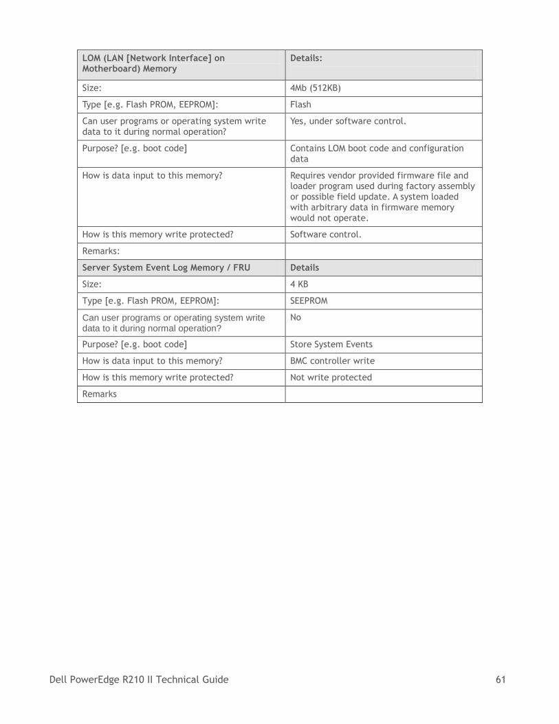
Dell PowerEdge R210 II Technical Guide 61
LOM (LAN [Network Interface] on Motherboard) Memory
Details:
Size: 4Mb (512KB)
Type [e.g. Flash PROM, EEPROM]: Flash
Can user programs or operating system write data to it during normal operation?
Yes, under software control.
Purpose? [e.g. boot code] Contains LOM boot code and configuration data
How is data input to this memory? Requires vendor provided firmware file and loader program used during factory assembly or possible field update. A system loaded with arbitrary data in firmware memory would not operate.
How is this memory write protected? Software control.
Remarks:
Server System Event Log Memory / FRU Details
Size: 4 KB
Type [e.g. Flash PROM, EEPROM]: SEEPROM
Can user programs or operating system write data to it during normal operation?
No
Purpose? [e.g. boot code] Store System Events
How is data input to this memory? BMC controller write
How is this memory write protected? Not write protected
Remarks
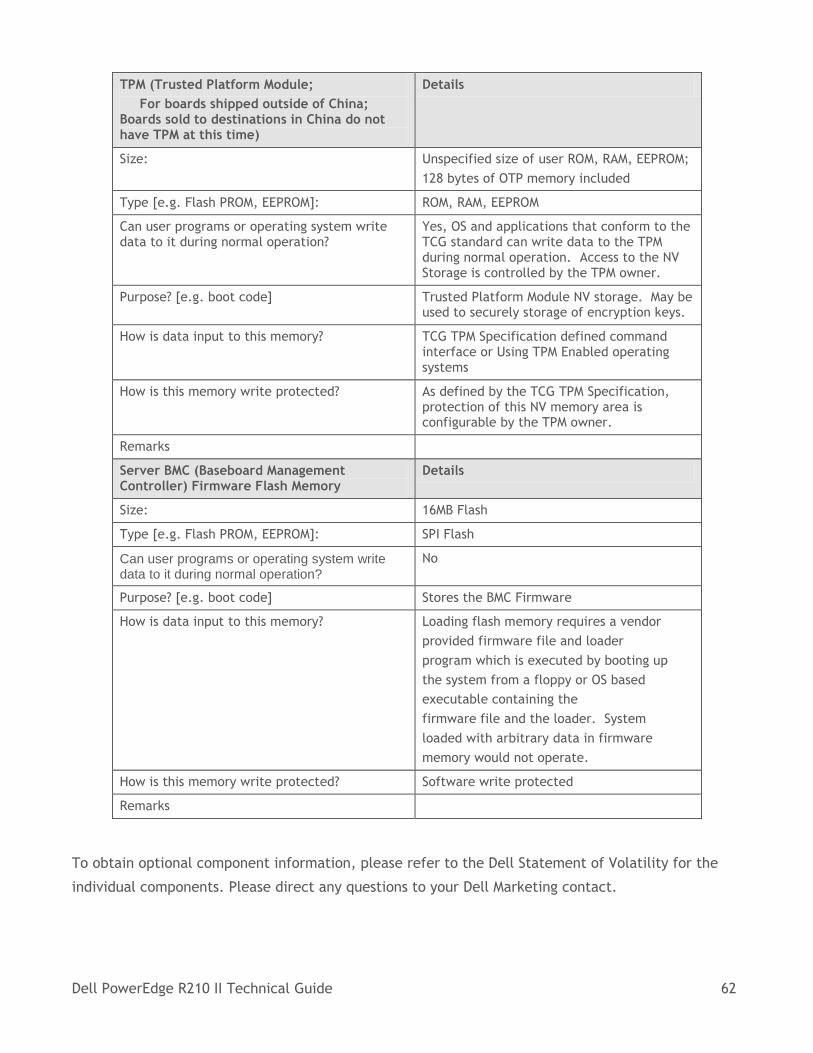
Dell PowerEdge R210 II Technical Guide 62
TPM (Trusted Platform Module;
For boards shipped outside of China; Boards sold to destinations in China do not have TPM at this time)
Details
Size: Unspecified size of user ROM, RAM, EEPROM;
128 bytes of OTP memory included
Type [e.g. Flash PROM, EEPROM]: ROM, RAM, EEPROM
Can user programs or operating system write data to it during normal operation?
Yes, OS and applications that conform to the TCG standard can write data to the TPM during normal operation. Access to the NV Storage is controlled by the TPM owner.
Purpose? [e.g. boot code] Trusted Platform Module NV storage. May be used to securely storage of encryption keys.
How is data input to this memory? TCG TPM Specification defined command interface or Using TPM Enabled operating systems
How is this memory write protected? As defined by the TCG TPM Specification, protection of this NV memory area is configurable by the TPM owner.
Remarks
Server BMC (Baseboard Management Controller) Firmware Flash Memory
Details
Size: 16MB Flash
Type [e.g. Flash PROM, EEPROM]: SPI Flash
Can user programs or operating system write data to it during normal operation?
No
Purpose? [e.g. boot code] Stores the BMC Firmware
How is data input to this memory? Loading flash memory requires a vendor
provided firmware file and loader
program which is executed by booting up
the system from a floppy or OS based
executable containing the
firmware file and the loader. System
loaded with arbitrary data in firmware
memory would not operate.
How is this memory write protected? Software write protected
Remarks
To obtain optional component information, please refer to the Dell Statement of Volatility for the
individual components. Please direct any questions to your Dell Marketing contact.

Dell PowerEdge R210 II Technical Guide 63
Appendix B. Certifications
B 1. Regulatory Certifications
Regulatory compliance certificates can be located at the following site:
http://www.dell.com/content/topics/global.aspx/about_dell/values/regulatory_compliance
/dec_conform?c=us&l=en&s=corp
B 2. Product Safety Certifications
The product has been certified and bears the Mark, as applicable, of the Product Safety authorities
as indicated in Table 21.
Table 21. Product Safety Certifications
Country/Region Authority or Mark
Argentina IRAM
Belarus BELLIS
Canada SCC
China CNCA or CCC
Croatia KONCAR
European Union CE
Germany TUV
IECEE IECEE CB
Israel SII
Kazakhstan OTAN – CKT
Kenya KEBS
Kuwait KUCAS
Mexico NYCE or NOM
Moldova INSM
Nigeria SONCAP
Norway NEMKO
Russia GOST
Saudi Arabia KSA ICCP
South Africa NRCS
Taiwan BSMI
Ukraine
UKRTEST or
UKRSERTCOMPUTER
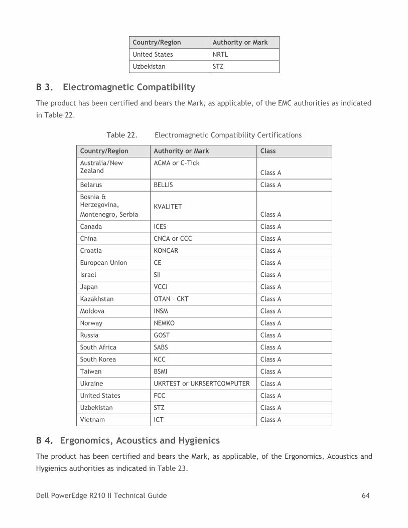
Dell PowerEdge R210 II Technical Guide 64
Country/Region Authority or Mark
United States NRTL
Uzbekistan STZ
B 3. Electromagnetic Compatibility
The product has been certified and bears the Mark, as applicable, of the EMC authorities as indicated
in Table 22.
Table 22. Electromagnetic Compatibility Certifications
Country/Region Authority or Mark Class
Australia/New Zealand
ACMA or C-Tick
Class A
Belarus BELLIS Class A
Bosnia & Herzegovina,
Montenegro, Serbia
KVALITET Class A
Canada ICES Class A
China CNCA or CCC Class A
Croatia KONCAR Class A
European Union CE Class A
Israel SII Class A
Japan VCCI Class A
Kazakhstan OTAN – CKT Class A
Moldova INSM Class A
Norway NEMKO Class A
Russia GOST Class A
South Africa SABS Class A
South Korea KCC Class A
Taiwan BSMI Class A
Ukraine UKRTEST or UKRSERTCOMPUTER Class A
United States FCC Class A
Uzbekistan STZ Class A
Vietnam ICT Class A
B 4. Ergonomics, Acoustics and Hygienics
The product has been certified and bears the Mark, as applicable, of the Ergonomics, Acoustics and
Hygienics authorities as indicated in Table 23.
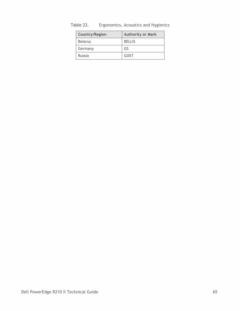
Dell PowerEdge R210 II Technical Guide 65
Table 23. Ergonomics, Acoustics and Hygienics
Country/Region Authority or Mark
Belarus BELLIS
Germany GS
Russia GOST
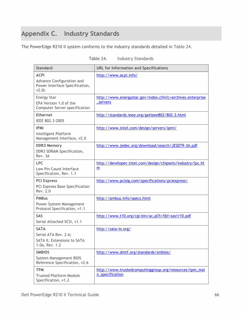
Dell PowerEdge R210 II Technical Guide 66
Appendix C. Industry Standards
The PowerEdge R210 II system conforms to the industry standards detailed in Table 24.
Table 24. Industry Standards
Standard URL for Information and Specifications
ACPI
Advance Configuration and Power Interface Specification, v2.0c
http://www.acpi.info/
Energy Star
EPA Version 1.0 of the Computer Server specification
http://www.energystar.gov/index.cfm?c=archives.enterprise_servers
Ethernet
IEEE 802.3-2005
http://standards.ieee.org/getieee802/802.3.html
IPMI
Intelligent Platform Management Interface, v2.0
http://www.intel.com/design/servers/ipmi/
DDR3 Memory
DDR3 SDRAM Specification, Rev. 3A
http://www.jedec.org/download/search/JESD79-3A.pdf
LPC
Low Pin Count Interface Specification, Rev. 1.1
http://developer.intel.com/design/chipsets/industry/lpc.htm
PCI Express
PCI Express Base Specification Rev. 2.0
http://www.pcisig.com/specifications/pciexpress/
PMBus
Power System Management Protocol Specification, v1.1
http://pmbus.info/specs.html
SAS
Serial Attached SCSI, v1.1
http://www.t10.org/cgi-bin/ac.pl?t=f&f=sas1r10.pdf
SATA
Serial ATA Rev. 2.6;
SATA II, Extensions to SATA 1.0a, Rev. 1.2
http://sata-io.org/
SMBIOS
System Management BIOS Reference Specification, v2.6
http://www.dmtf.org/standards/smbios/
TPM
Trusted Platform Module Specification, v1.2
http://www.trustedcomputinggroup.org/resources/tpm_main_specification
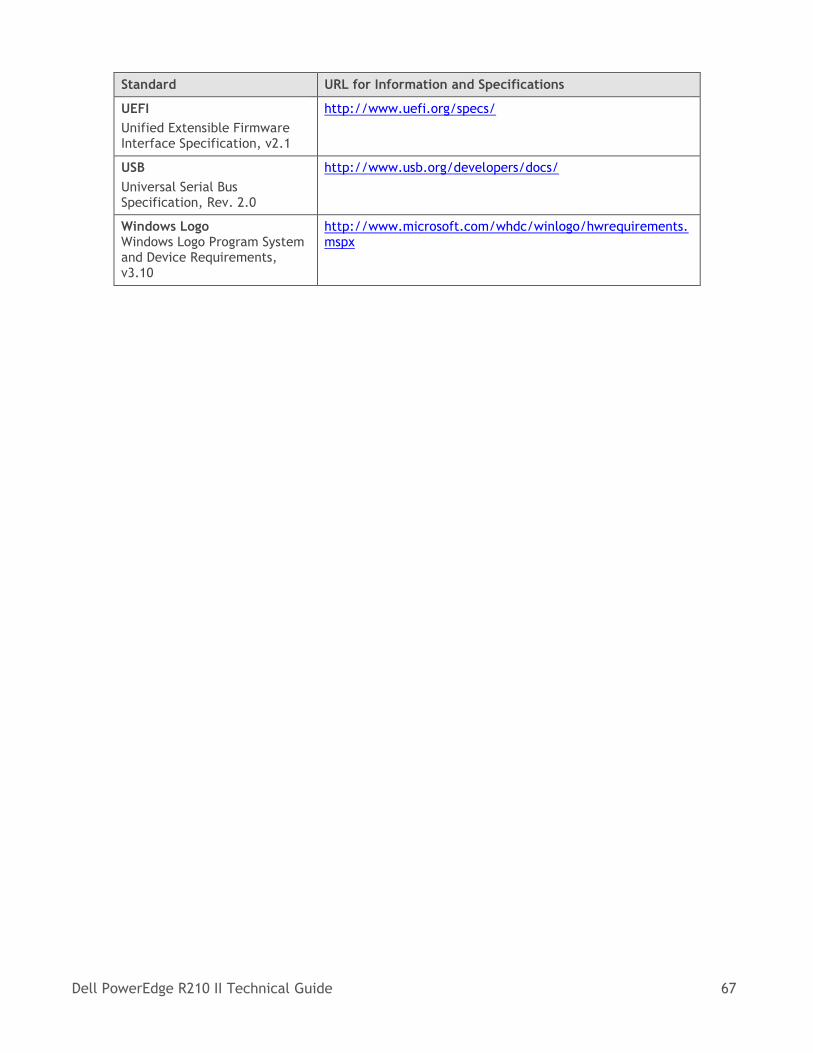
Dell PowerEdge R210 II Technical Guide 67
Standard URL for Information and Specifications
UEFI
Unified Extensible Firmware Interface Specification, v2.1
http://www.uefi.org/specs/
USB
Universal Serial Bus Specification, Rev. 2.0
http://www.usb.org/developers/docs/
Windows Logo Windows Logo Program System and Device Requirements, v3.10
http://www.microsoft.com/whdc/winlogo/hwrequirements.mspx