Embed Size (px)
Citation preview
PR
OD
UC
T I
NF
OR
MA
TIO
N
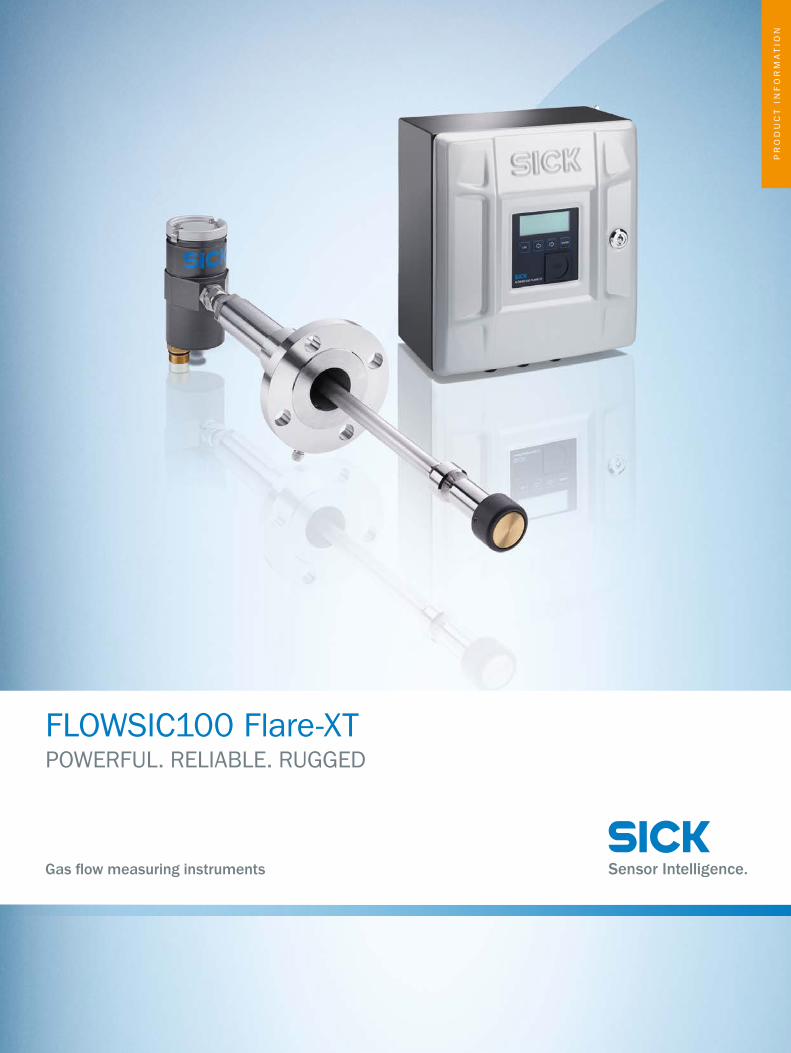
FLOWSIC100 Flare-XTPOWERFUL. RELIABLE. RUGGED
Gas flow measuring instruments

G A S F L O W M E A S U R I N G I N S T R U M E N T S | S I C K 8023684/2021-03Subject to change without notice
2
FLOWSIC100 Flare-XT: Powerful. Reliable. Rugged.
Increasing competition in the process industry means that operations and service work have to be optimized continuously. When it comes to flare gas measurement, the new FLOWSIC100 Flare-XT make saving costs so easy. State-of-the-art ultrasonic measuring technology provides maximum performance and robustness. As a result, the sensor continuously calculates accurate values even under extremely unstable conditions. An addition to this: Thanks to i-diagnostics™, the system monitors itself and informs the user in realtime when maintenance is due, thereby making fix ser-vice intervals a thing of the past. We think that’s intelligent.
G A S F L O W M E A S U R I N G I N S T R U M E N T S | S I C K8023684/2021-03Subject to change without notice
3
POWERFUL. RELIABLE. RUGGED FLOWSIC100 Flare-XT
FLARE GAS MEASUREMENT REDEFINED: FLOWSIC100 Flare-XTDealing with difficult flare gas conditions the requirements for measuring technology pose a challenge in the oil and gas and the chemical and petrochemical industry:
• Gas velocities of 0 to 120 m/s • Rapid changes in the gas velocity • Rapidly changing gas mixtures natural gas, hydrogen, carbon dioxide, etc.
Ultrasonic flow meters continue to set the standard in Flow Measurement when it comes to dynamic range and accuracy. With FLOWSIC100 Flare-XT, SICK has developed a new generation of ultrasonic measuring devices that work completely reliably and accurately even under extreme conditions, are installed in next to no time and constantly monitor themselves thanks to the self-diagnostics function i-diagnostics™.
FLOWSIC100 Flare-XT at a glance:
• Measurement availability even at high gas velocities and with changing gas mixtures • Proprietary measurement range extension for high flow velocities thanks to ASC-technology (active sound correlation) • Intuitive FLOWgate™ operating software • i-diagnostics™ for self-monitoring, easy testing and preventive maintenance of the complete system • Retrofit solution for existing measurement systems
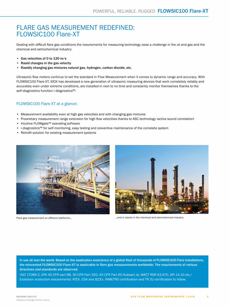
…and in plants in the chemical and petrochemical industryFlare gas measurement on offshore platforms…
In use all over the world. Based on the application experience of a global fleet of thousands of FLOWSIC100 Flare installations, the reinvented FLOWSIC100 Flare-XT is applicable in flare gas measurements worldwide. The requirements of various directives and standards are observed.(ISO 17089-2, EPA 40 CFR part 98, 30 CFR Part 250, 40 CFR Part 60 Subpart Ja, MACT RSR 63.670, API 14.10 etc.) Explosion protection requirements: ATEX, CSA and IECEx. INMETRO certification and TR ZU certification to follow.
G A S F L O W M E A S U R I N G I N S T R U M E N T S | S I C K 8023684/2021-03Subject to change without notice
4
FLOWSIC100 Flare-XT POWERFUL. RELIABLE. RUGGED
THE RIGHT SOLUTION FOR EVERY CHALLENGE
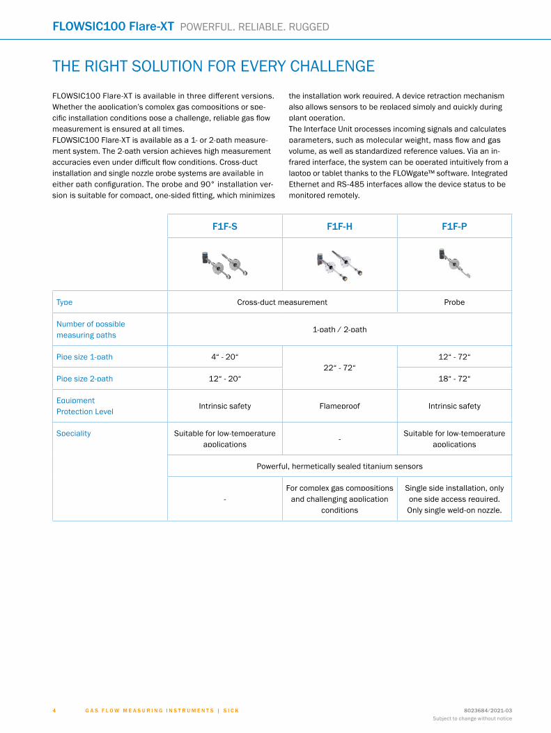
FLOWSIC100 Flare-XT is available in three different versions. Whether the application’s complex gas compositions or spe-cific installation conditions pose a challenge, reliable gas flow measurement is ensured at all times.FLOWSIC100 Flare-XT is available as a 1- or 2-path measure-ment system. The 2-path version achieves high measurement accuracies even under difficult flow conditions. Cross-duct installation and single nozzle probe systems are available in either path configuration. The probe and 90° installation ver-sion is suitable for compact, one-sided fitting, which minimizes
the installation work required. A device retraction mechanism also allows sensors to be replaced simply and quickly during plant operation.The Interface Unit processes incoming signals and calculates parameters, such as molecular weight, mass flow and gas volume, as well as standardized reference values. Via an in-frared interface, the system can be operated intuitively from a laptop or tablet thanks to the FLOWgate™ software. Integrated Ethernet and RS-485 interfaces allow the device status to be monitored remotely.
F1F-S F1F-H F1F-P
Type Cross-duct measurement Probe
Number of possible measuring paths
1-path / 2-path
Pipe size 1-path 4“ - 20“22“ - 72“
12“ - 72“
Pipe size 2-path 12“ - 20“ 18“ - 72“
Equipment Protection Level
Intrinsic safety Flameproof Intrinsic safety
Speciality Suitable for low-temperature applications
-Suitable for low-temperature
applications
Powerful, hermetically sealed titanium sensors
-For complex gas compositions
and challenging application conditions
Single side installation, only one side access required.Only single weld-on nozzle.
G A S F L O W M E A S U R I N G I N S T R U M E N T S | S I C K8023684/2021-03Subject to change without notice
5
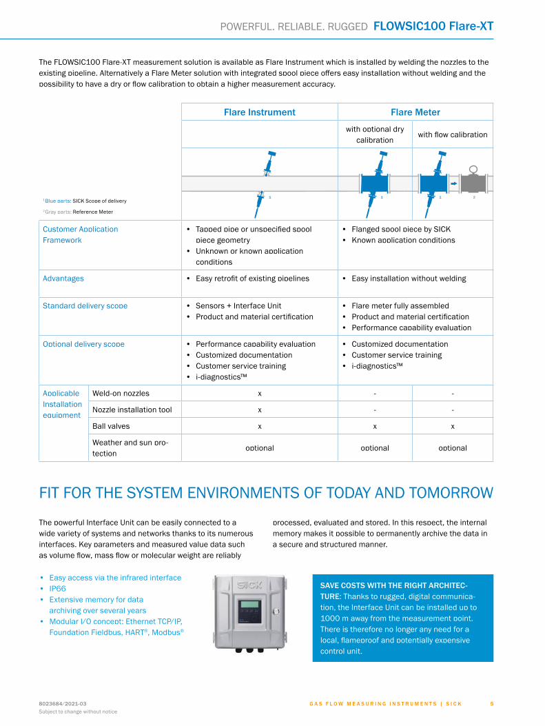
1 1 1 2
Flare Instrument Flare Meter
with optional dry calibration
with flow calibration
1Blue parts: SICK Scope of delivery
2Gray parts: Reference Meter
Customer Application Framework
• Tapped pipe or unspecified spool piece geometry
• Unknown or known application conditions
• Flanged spool piece by SICK • Known application conditions
Advantages • Easy retrofit of existing pipelines • Easy installation without welding
Standard delivery scope • Sensors + Interface Unit • Product and material certification
• Flare meter fully assembled • Product and material certification • Performance capability evaluation
Optional delivery scope • Performance capability evaluation • Customized documentation • Customer service training • i-diagnostics™
• Customized documentation • Customer service training • i-diagnostics™
Applicable Installation equipment
Weld-on nozzles x - -
Nozzle installation tool x - -
Ball valves x x x
Weather and sun pro-tection
optional optional optional
POWERFUL. RELIABLE. RUGGED FLOWSIC100 Flare-XT
The FLOWSIC100 Flare-XT measurement solution is available as Flare Instrument which is installed by welding the nozzles to the existing pipeline. Alternatively a Flare Meter solution with integrated spool piece offers easy installation without welding and the possibility to have a dry or flow calibration to obtain a higher measurement accuracy.
FIT FOR THE SYSTEM ENVIRONMENTS OF TODAY AND TOMORROW
The powerful Interface Unit can be easily connected to a wide variety of systems and networks thanks to its numerous interfaces. Key parameters and measured value data such as volume flow, mass flow or molecular weight are reliably
processed, evaluated and stored. In this respect, the internal memory makes it possible to permanently archive the data in a secure and structured manner.
• Easy access via the infrared interface • IP66 • Extensive memory for data
archiving over several years • Modular I/O concept: Ethernet TCP/IP,
Foundation Fieldbus, HART®, Modbus®
SAVE COSTS WITH THE RIGHT ARCHITEC-TURE: Thanks to rugged, digital communica-tion, the Interface Unit can be installed up to 1000 m away from the measurement point. There is therefore no longer any need for a local, flameproof and potentially expensive control unit.
G A S F L O W M E A S U R I N G I N S T R U M E N T S | S I C K 8023684/2021-03Subject to change without notice
6
A
B
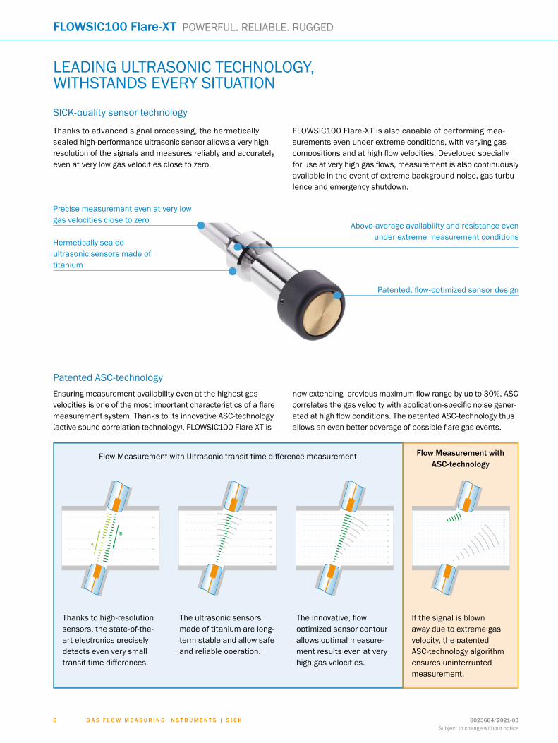
Thanks to advanced signal processing, the hermetically sealed high-performance ultrasonic sensor allows a very high resolution of the signals and measures reliably and accurately even at very low gas velocities close to zero.
FLOWSIC100 Flare-XT is also capable of performing mea-surements even under extreme conditions, with varying gas compositions and at high flow velocities. Developed specially for use at very high gas flows, measurement is also continuously available in the event of extreme background noise, gas turbu-lence and emergency shutdown.
Hermetically sealedultrasonic sensors made of titanium
Precise measurement even at very lowgas velocities close to zero
Above-average availability and resistance even under extreme measurement conditions
Patented, flow-optimized sensor design
LEADING ULTRASONIC TECHNOLOGY, WITHSTANDS EVERY SITUATION
SICK-quality sensor technology
FLOWSIC100 Flare-XT POWERFUL. RELIABLE. RUGGED
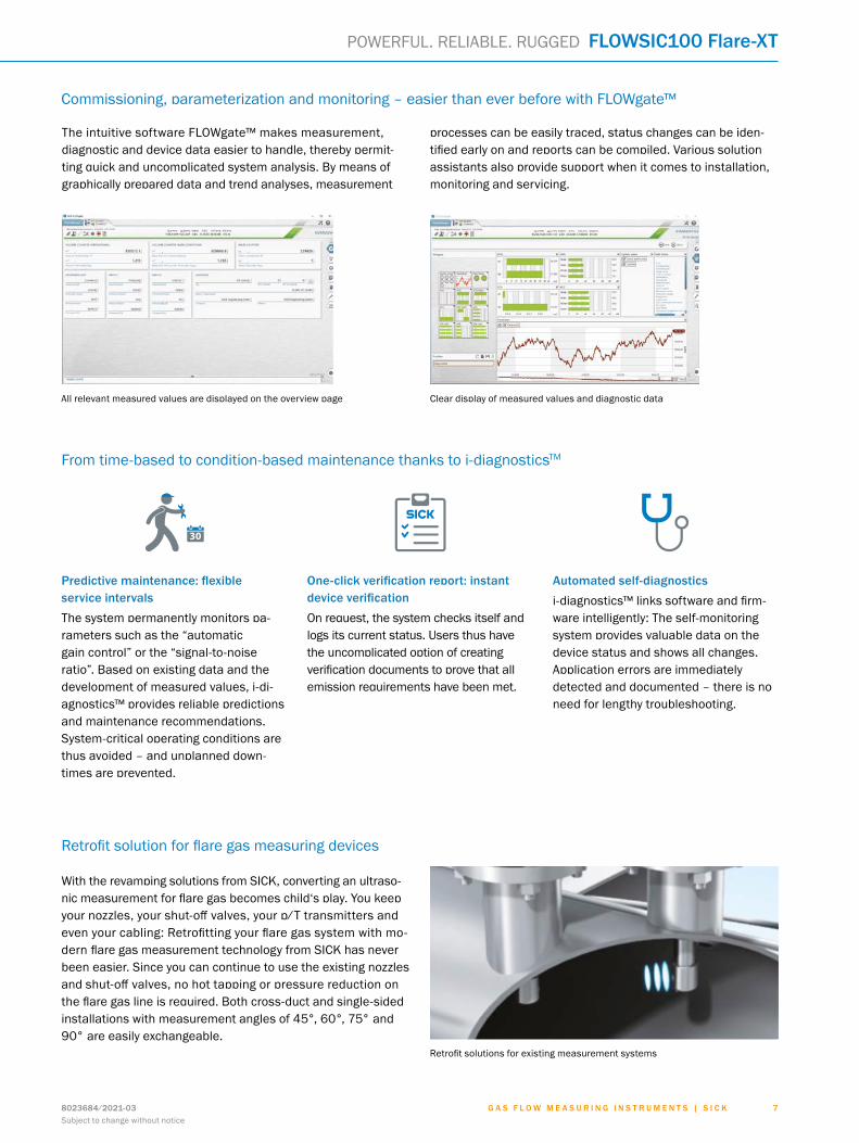
Patented ASC-technologyEnsuring measurement availability even at the highest gas velocities is one of the most important characteristics of a flare measurement system. Thanks to its innovative ASC-technology (active sound correlation technology), FLOWSIC100 Flare-XT is
now extending previous maximum flow range by up to 30%. ASC correlates the gas velocity with application-specific noise gener-ated at high flow conditions. The patented ASC-technology thus allows an even better coverage of possible flare gas events.
Thanks to high-resolution sensors, the state-of-the-art electronics precisely detects even very small transit time differences.
The ultrasonic sensors made of titanium are long-term stable and allow safe and reliable operation.
The innovative, flow optimized sensor contour allows optimal measure-ment results even at very high gas velocities.
If the signal is blown away due to extreme gas velocity, the patented ASC-technology algorithm ensures uninterrupted measurement.
Flow Measurement with Ultrasonic transit time difference measurement Flow Measurement with ASC-technology
G A S F L O W M E A S U R I N G I N S T R U M E N T S | S I C K8023684/2021-03Subject to change without notice
7
POWERFUL. RELIABLE. RUGGED FLOWSIC100 Flare-XT
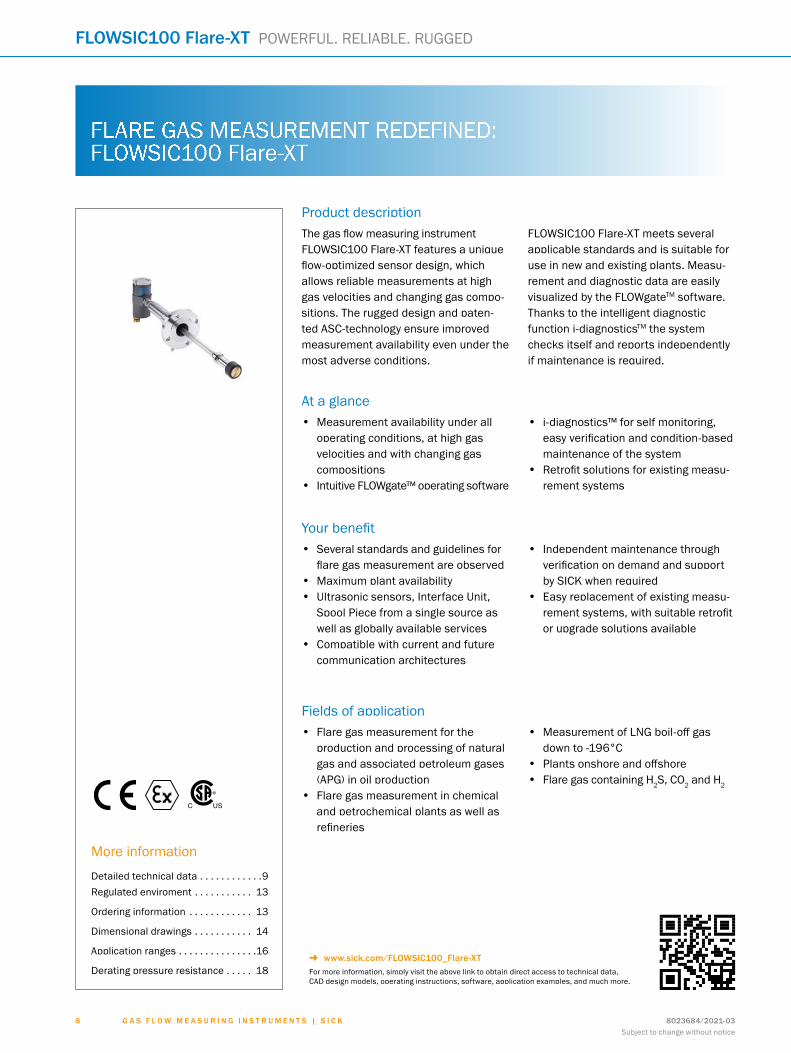
The intuitive software FLOWgate™ makes measurement, diagnostic and device data easier to handle, thereby permit-ting quick and uncomplicated system analysis. By means of graphically prepared data and trend analyses, measurement
processes can be easily traced, status changes can be iden-tified early on and reports can be compiled. Various solution assistants also provide support when it comes to installation, monitoring and servicing.
All relevant measured values are displayed on the overview page Clear display of measured values and diagnostic data
Commissioning, parameterization and monitoring – easier than ever before with FLOWgate™
From time-based to condition-based maintenance thanks to i-diagnosticsTM
Predictive maintenance: flexible service intervals The system permanently monitors pa-rameters such as the “automatic gain control” or the “signal-to-noise ratio”. Based on existing data and the development of measured values, i-di-agnostics™ provides reliable predictions and maintenance recommendations. System-critical operating conditions are thus avoided – and unplanned down-times are prevented.
One-click verification report: instant device verificationOn request, the system checks itself and logs its current status. Users thus have the uncomplicated option of creating verification documents to prove that all emission requirements have been met.
Automated self-diagnosticsi-diagnostics™ links software and firm-ware intelligently: The self-monitoring system provides valuable data on the device status and shows all changes. Application errors are immediately detected and documented – there is no need for lengthy troubleshooting.
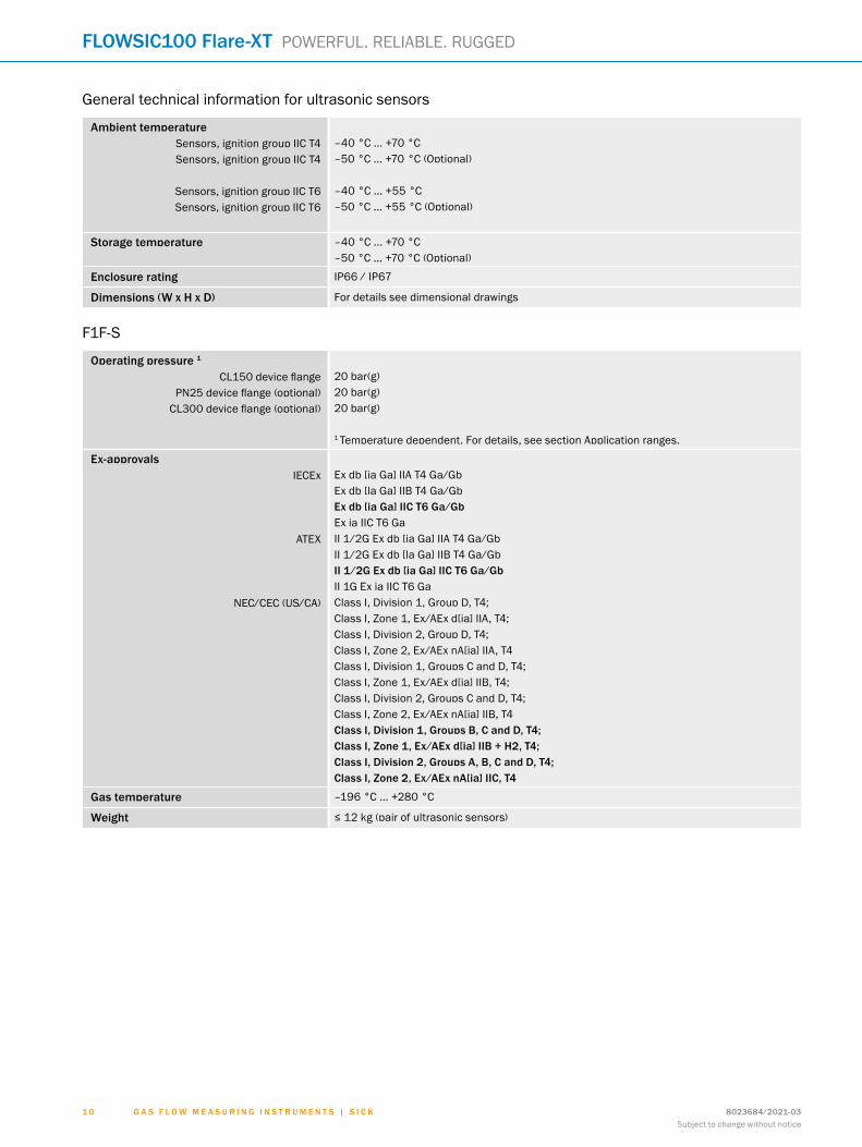
With the revamping solutions from SICK, converting an ultraso-nic measurement for flare gas becomes child‘s play. You keep your nozzles, your shut-off valves, your p/T transmitters and even your cabling: Retrofitting your flare gas system with mo-dern flare gas measurement technology from SICK has never been easier. Since you can continue to use the existing nozzles and shut-off valves, no hot tapping or pressure reduction on the flare gas line is required. Both cross-duct and single-sided installations with measurement angles of 45°, 60°, 75° and 90° are easily exchangeable.
Retrofit solution for flare gas measuring devices
Retrofit solutions for existing measurement systems
Product descriptionThe gas flow measuring instrument FLOWSIC100 Flare-XT features a unique flow-optimized sensor design, which allows reliable measurements at high gas velocities and changing gas compo-sitions. The rugged design and paten-ted ASC-technology ensure improved measurement availability even under the most adverse conditions.
FLOWSIC100 Flare-XT meets several applicable standards and is suitable for use in new and existing plants. Measu-rement and diagnostic data are easily visualized by the FLOWgateTM software. Thanks to the intelligent diagnostic function i-diagnosticsTM the system checks itself and reports independently if maintenance is required.
At a glance• Measurement availability under all
operating conditions, at high gas velocities and with changing gas compositions
• Intuitive FLOWgate™ operating software
• i-diagnostics™ for self monitoring, easy verification and condition-based maintenance of the system
• Retrofit solutions for existing measu-rement systems
Your benefit• Several standards and guidelines for
flare gas measurement are observed• Maximum plant availability • Ultrasonic sensors, Interface Unit,
Spool Piece from a single source as well as globally available services
• Compatible with current and future communication architectures
• Independent maintenance through verification on demand and support by SICK when required
• Easy replacement of existing measu-rement systems, with suitable retrofit or upgrade solutions available
Fields of application• Flare gas measurement for the
production and processing of natural gas and associated petroleum gases (APG) in oil production
• Flare gas measurement in chemical and petrochemical plants as well as refineries
• Measurement of LNG boil-off gas down to -196°C
• Plants onshore and offshore• Flare gas containing H2S, CO2 and H2
FLARE GAS MEASUREMENT REDEFINED: FLOWSIC100 Flare-XT
More information
Detailed technical data . . . . . . . . . . . .9 Regulated enviroment . . . . . . . . . . . 13
Ordering information . . . . . . . . . . . . 13
Dimensional drawings . . . . . . . . . . . 14
Application ranges . . . . . . . . . . . . . . .16
Derating pressure resistance . . . . . 18
C US
®
- www.sick.com/FLOWSIC100_Flare-XTFor more information, simply visit the above link to obtain direct access to technical data, CAD design models, operating instructions, software, application examples, and much more.
G A S F L O W M E A S U R I N G I N S T R U M E N T S | S I C K 8023684/2021-03Subject to change without notice
8
FLOWSIC100 Flare-XT POWERFUL. RELIABLE. RUGGED

Detailed technical dataThe exact device specifications and performance data of the product may deviate from the information provided here, and depend on the application in which the product is being used and the relevant customer specifications. Please contact your local SICK representative to inquire about the FLOWSIC100 Flare-XT performance for your application.
System FLOWSIC100 Flare-XT
Measured values Mass flow rate, volumetric flow s. c. (standard condition), volumetric flow a. c. (actual condition), molecular weight, gas volume and mass, gas velocity, gas temperature, sound velocity
Number of measuring paths Single path, Dual path
Nominal pipe size1-path measurement2-path measurement
4 ″ ... 72 ″12 ″ ... 72 ″Other nominal sizes on request
Measurement principle Ultrasonic transit time difference measurement, ASC-technology (active sound correlation)
Measuring medium Typical flare gas
Measuring ranges 1 0.03 m/s ... 120 m/s
Measuring span 1 Up to 4000:1
Repeatability (acc to ISO 5725-1; JCGM 200:2012): < 0.5 % of the measured value in the range ≥ 1 m/s
Resolution (acc. to JCGM 200:2012): + 0.001 m/s
Uncertainty of measurement 1-3
Volumetric flow a. c.
Mass flow rate
1 % … 5 %Related to the measured value with ultrasonic technology (in the range ≥ 0.3 m/s to measuring range end value)
0.5 % … 1.5 % with Spool Piece and flow calibrationRelated to the measured value with ultrasonic technology (in the range ≥ 1 m/s to calibration range end value) 4
2 % … 5.5 %Related to the measured value with ultrasonic technology (in the range ≥ 0.3 m/s to measuring range end value)
1.5 % … 2 % with Spool Piece and flow calibrationRelated to the measured value with ultrasonic technology (in the range ≥ 1 m/s to calibration range end value) 4
Uncertainty of measurement ASC-technology 1,2,5
Volumetric flow a. c. 1 % … 8 %
Ambient humidity ≤ 95 % Relative humidity
Conformities ATEX: 2014/34/EUEMC: 2014/30/EURoHS: 2011/65/EUPED: 2014/68/EU
Electrical safety IEC 61010-1
Footnote 1 Depending on the application conditions such as gas composition, process temperature, type of device, pipe diameter, etc. For mass flow additionally selection and parameteri- zation of the conversion algorithm as well as uncertainty of the pressure and temperature sensors. To be evaluated by SICK.2 With fully developed turbulent flow profile. Typically 20D straight upstream and 5D straight downstream piping is required.3 Below a specific threshold Reynolds number, only run time effects and uncertainties of geometry, excluding contributions from the flow profile are considered.4 Depending on the capabilities of the selected flow lab.5 Additional uncertainty. In the range 100 % ... 130 % of the last gas velocity measurable with ultrasonic transit time difference measurement.
G A S F L O W M E A S U R I N G I N S T R U M E N T S | S I C K8023684/2021-03Subject to change without notice
9
POWERFUL. RELIABLE. RUGGED FLOWSIC100 Flare-XT
General technical information for ultrasonic sensors
Ambient temperatureSensors, ignition group IIC T4 Sensors, ignition group IIC T4
Sensors, ignition group IIC T6Sensors, ignition group IIC T6
–40 °C ... +70 °C–50 °C ... +70 °C (Optional)
–40 °C ... +55 °C–50 °C ... +55 °C (Optional)
Storage temperature –40 °C ... +70 °C–50 °C ... +70 °C (Optional)
Enclosure rating IP66 / IP67
Dimensions (W x H x D) For details see dimensional drawings
F1F-S
Operating pressure 1
CL150 device flangePN25 device flange (optional)
CL300 device flange (optional)
20 bar(g)20 bar(g)20 bar(g)
1 Temperature dependent. For details, see section Application ranges.
Ex-approvalsIECEx
ATEX
NEC/CEC (US/CA)
Ex db [ia Ga] IIA T4 Ga/GbEx db [la Ga] IIB T4 Ga/GbEx db [ia Ga] IIC T6 Ga/GbEx ia IIC T6 GaII 1/2G Ex db [ia Ga] IIA T4 Ga/GbII 1/2G Ex db [la Ga] IIB T4 Ga/GbII 1/2G Ex db [ia Ga] IIC T6 Ga/GbII 1G Ex ia IIC T6 GaClass I, Division 1, Group D, T4;Class I, Zone 1, Ex/AEx d[ia] IIA, T4;Class I, Division 2, Group D, T4;Class I, Zone 2, Ex/AEx nA[ia] IIA, T4Class I, Division 1, Groups C and D, T4;Class I, Zone 1, Ex/AEx d[ia] IIB, T4;Class I, Division 2, Groups C and D, T4;Class I, Zone 2, Ex/AEx nA[ia] IIB, T4Class I, Division 1, Groups B, C and D, T4;Class I, Zone 1, Ex/AEx d[ia] IIB + H2, T4;Class I, Division 2, Groups A, B, C and D, T4;Class I, Zone 2, Ex/AEx nA[ia] IIC, T4
Gas temperature –196 °C ... +280 °C
Weight ≤ 12 kg (pair of ultrasonic sensors)
G A S F L O W M E A S U R I N G I N S T R U M E N T S | S I C K 8023684/2021-03Subject to change without notice
1 0
FLOWSIC100 Flare-XT POWERFUL. RELIABLE. RUGGED
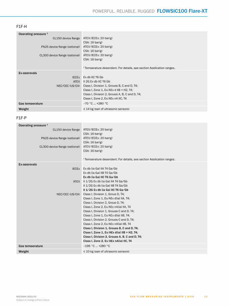
F1F-H
Operating pressure 1
CL150 device flange
PN25 device flange (optional)
CL300 device flange (optional)
ATEX/IECEx: 20 bar(g)CSA: 16 bar(g)ATEX/IECEx: 20 bar(g)CSA: 16 bar(g)ATEX/IECEx: 20 bar(g)CSA: 16 bar(g)
1 Temperature dependent. For details, see section Application ranges.
Ex-approvalsIECExATEX
NEC/CEC (US/CA)
Ex db IIC T6 GbII 2G Ex db IIC T6 GbClass I, Division 1, Groups B, C and D, T4;Class I, Zone 1, Ex/AEx d IIB + H2, T4;Class I, Division 2, Groups A, B, C and D, T4;Class I, Zone 2, Ex/AEx nA IIC, T4
Gas temperature –70 °C ... +280 °C
Weight ≤ 14 kg (pair of ultrasonic sensors)
F1F-P
Operating pressure 1
CL150 device flange
PN25 device flange (optional)
CL300 device flange (optional)
ATEX/IECEx: 20 bar(g)CSA: 16 bar(g)ATEX/IECEx: 20 bar(g)CSA: 16 bar(g)ATEX/IECEx: 20 bar(g)CSA: 16 bar(g)
1 Temperature dependent. For details, see section Application ranges.
Ex-approvalsIECEx
ATEX
NEC/CEC (US/CA)
Ex db [ia Ga] IIA T4 Ga/GbEx db [ia Ga] IIB T4 Ga/GbEx db [ia Ga] IIC T6 Ga/GbII 1/2G Ex db [ia Ga] IIA T4 Ga/GbII 1/2G Ex db [ia Ga] IIB T4 Ga/GbII 1/2G Ex db [ia Ga] IIC T6 Ga/GbClass I, Division 1, Group D, T4;Class I, Zone 1, Ex/AEx d[ia] IIA, T4;Class I, Division 2, Group D, T4;Class I, Zone 2, Ex/AEx nA[ia] IIA, T4Class I, Division 1, Groups C and D, T4;Class I, Zone 1, Ex/AEx d[ia] IIB, T4;Class I, Division 2, Groups C and D, T4;Class I, Zone 2, Ex/AEx nA[ia] IIB, T4Class I, Division 1, Groups B, C and D, T4;Class I, Zone 1, Ex/AEx d[ia] IIB + H2, T4;Class I, Division 2, Groups A, B, C and D, T4;Class I, Zone 2, Ex/AEx nA[ia] IIC, T4
Gas temperature –196 °C ... +280 °C
Weight ≤ 10 kg (pair of ultrasonic sensors)
G A S F L O W M E A S U R I N G I N S T R U M E N T S | S I C K8023684/2021-03Subject to change without notice
1 1
POWERFUL. RELIABLE. RUGGED FLOWSIC100 Flare-XT
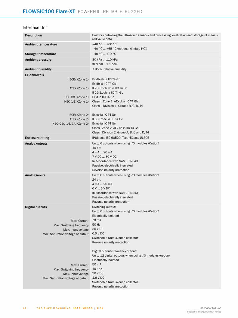
Interface Unit
Description Unit for controlling the ultrasonic sensors and processing, evaluation and storage of measu-red value data
Ambient temperature –40 °C ... +60 °C–40 °C ... +65 °C (optional (limited I/O))
Storage temperature –40 °C ... +70 °C
Ambient pressure 80 kPa ... 110 kPa(0.8 bar .. 1.1 bar)
Ambient humidity ≤ 95 % Relative humidity
Ex-approvalsIECEx (Zone 1)
ATEX (Zone 1)
CEC (CA) (Zone 1)NEC (US) (Zone 1)
IECEx (Zone 2)ATEX (Zone 2)
NEC/CEC (US/CA) (Zone 2)
Ex db eb ia IIC T4 GbEx db ia IIC T4 GbII 2G Ex db eb ia IIC T4 GbII 2G Ex db ia IIC T4 GbEx d ia IIC T4 GbClass I, Zone 1, AEx d ia IIC T4 GbClass I, Division 1, Groups B, C, D, T4
Ex ec ia IIC T4 GcII 3G Ex ec ia IIC T4 GcEx ec ia IIC T4 GcClass I Zone 2, AEx ec ia IIC T4 GcClass I Division 2, Group A, B, C and D, T4
Enclosure rating IP66 acc. IEC 60529, Type 4X acc. UL50E
Analog outputs Up to 6 outputs when using I/O modules (Option)16 bit:4 mA ... 20 mA7 V DC ... 30 V DCIn accordance with NAMUR NE43Passive, electrically insulatedReverse polarity protection
Analog inputs Up to 6 outputs when using I/O modules (Option)24 bit:4 mA ... 20 mA0 V ... 5 V DCIn accordance with NAMUR NE43Passive, electrically insulatedReverse polarity protection
Digital outputs
Max. Current Max. Switching frequency
Max. Input voltageMax. Saturation voltage at output
Max. Current Max. Switching frequency
Max. Input voltageMax. Saturation voltage at output
Switching output:Up to 6 outputs when using I/O modules (Option)Electrically isolated70 mA50 Hz30 V DC0.5 V DCSwitchable Namur/open collectorReverse polarity protection
Digital output/frequency output:Up to 12 digital outputs when using I/O modules (option)Electrically isolated50 mA10 kHz30 V DC1.8 V DCSwitchable Namur/open collectorReverse polarity protection
G A S F L O W M E A S U R I N G I N S T R U M E N T S | S I C K 8023684/2021-03Subject to change without notice
1 2
FLOWSIC100 Flare-XT POWERFUL. RELIABLE. RUGGED
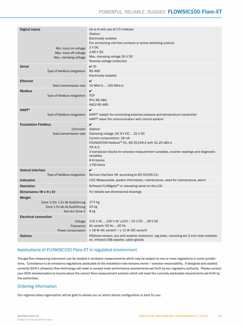
Digital inputs
Min. input on voltageMax. input off voltage
Max. clamping voltage
Up to 6 with use of I/O modules(Option)Electrically isolatedFor connecting volt-free contacts or active switching outputs2 V DC2.85 V DCMax. clamping voltage 30 V DCReverse voltage protection
SerialType of fieldbus integration
l (3)RS-485Electrically isolated
EthernetData transmission rate
l
10 Mbit/s ... 100 Mbit/s
ModbusType of fieldbus integration
l
TCPRTU RS-485ASCII RS-485
HART®
Type of fieldbus integrationl
HART® master for connecting external pressure and temperature transmitterHART® slave (for communication with control system)
Foundation FieldbusComment
Data transmission rate
l
(Option)Clamping voltage: DC 9 V DC … 32 V DCCurrent consumption: 18 mAFOUNDATION fieldbusTM H1, IEC 61158-2 with 31.25 kBit/sITK 6.3 3 transducer blocks for process measurement variables, counter readings and diagnostic variables8 AI blocks1 PID block
Optical interfaceType of fieldbus integration
l
Service interface (IR, according to IEC 62056-21)
Indication LCD: Measurands, system information, maintenance, need for maintenance, alarm
Operation Software FLOWgateTM or operating panel on the LCD
Dimensions (W x H x D) For details see dimensional drawings
WeightZone 1/Div 1 Ex db Ausführung
Zone 1 Ex db eb AusführungNon-Ex/Zone 2
17.5 kg23 kg8 kg
Electrical connectionVoltage
FrequencyPower consumption
115 V AC ... 230 V AC ±10% / 15 V DC ... 28 V DCAC variant: 50 Hz ... 60 Hz≤ 18 W (AC variant) / ≤ 12 W (DC variant)
Options Offshore-version, sun and weather protection, tag plate, mounting set 2-inch-pipe installati-on, infrared-USB adapter, cable glands
Applications of FLOWSIC100 Flare-XT in regulated environment
The gas flow measuring instrument can be applied in emission measurements which may be subject to one or more regulations in some jurisdic-tions. Compliance to all emissions regulations applicable at the installation site remains owner / operator responsibility. If designed and applied correctly SICK‘s ultrasonic flow technology will meet or exceed most performance requirements set forth by any regulatory authority. Please contact your SICK representative to inquire about the correct flare measurement solution which will meet the currently applicable requirements set forth by the authorities.
Ordering information
Our regional sales organization will be glad to advise you on which device configuration is best for you.
G A S F L O W M E A S U R I N G I N S T R U M E N T S | S I C K8023684/2021-03Subject to change without notice
1 3
POWERFUL. RELIABLE. RUGGED FLOWSIC100 Flare-XT
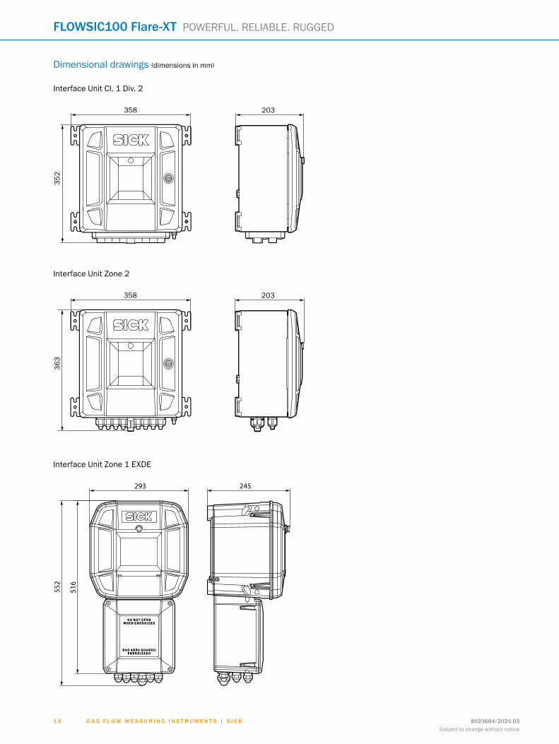
Dimensional drawings (dimensions in mm)
Interface Unit Cl. 1 Div. 2
358 203
352
Interface Unit Zone 2
358 203
363
Interface Unit Zone 1 EXDE
293 245
552
516
G A S F L O W M E A S U R I N G I N S T R U M E N T S | S I C K 8023684/2021-03Subject to change without notice
1 4
FLOWSIC100 Flare-XT POWERFUL. RELIABLE. RUGGED
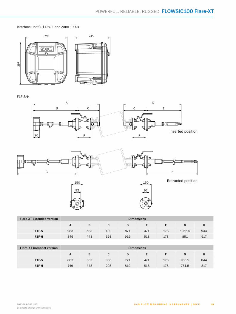
Interface Unit Cl.1 Div. 1 and Zone 1 EXD
293 245
297
F1F-S/H
A
B C C E
D
90
G H
150 150
92 92
Inserted position
Retracted position
F F
Flare-XT Extended version Dimensions
A B C D E F G H
F1F-S 983 583 400 871 471 178 1055.5 944
F1F-H 846 448 398 919 518 178 851 917
Flare-XT Compact version Dimensions
A B C D E F G H
F1F-S 883 583 300 771 471 178 955.5 844
F1F-H 746 448 298 819 518 178 751.5 817
G A S F L O W M E A S U R I N G I N S T R U M E N T S | S I C K8023684/2021-03Subject to change without notice
1 5
POWERFUL. RELIABLE. RUGGED FLOWSIC100 Flare-XT
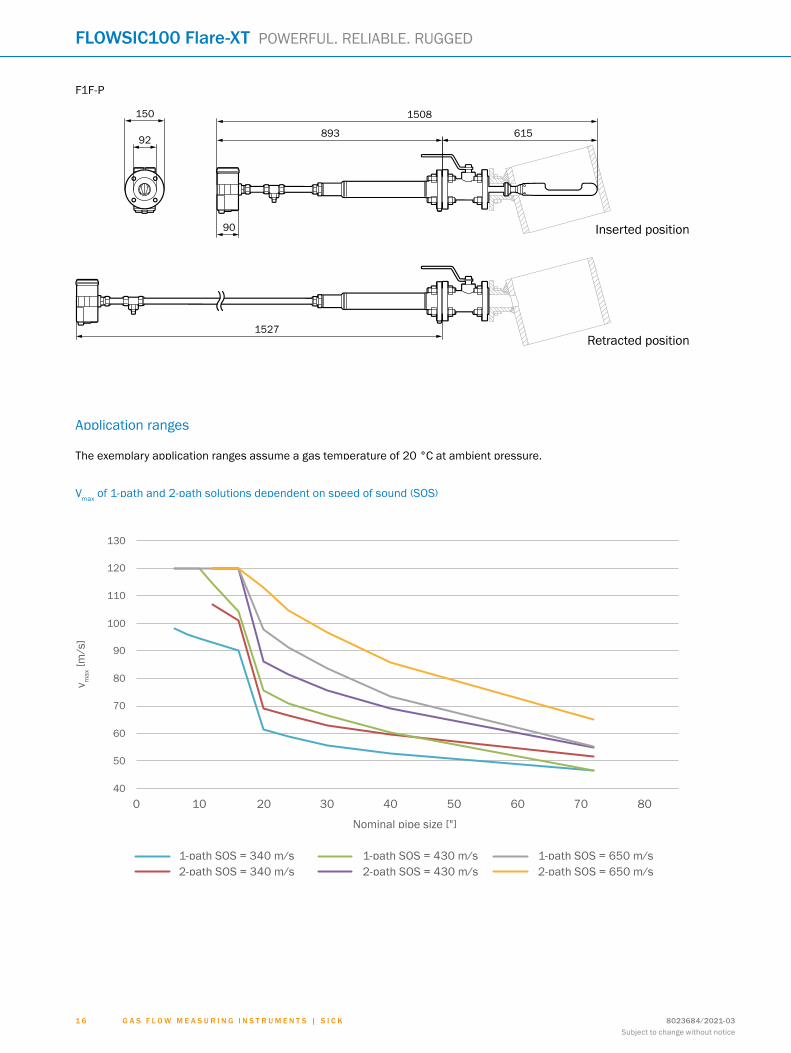
Application ranges
Vmax of 1-path and 2-path solutions dependent on speed of sound (SOS)
50
60
70
80
90
100
110
0 10 20 30 40 50 60 70 80
130
40
v max
in ft
/s
Nominal pipe size in ″
120
1-path sos = 340 m/s 1-path sos = 430 m/s 1-path sos = 650 m/s2-path sos = 340 m/s 2-path sos = 430 m/s 2-path sos = 650 m/s
The exemplary application ranges assume a gas temperature of 20 °C at ambient pressure.
F1F-P
1527
150
92
90
1508
893 615
Inserted position
Retracted position
G A S F L O W M E A S U R I N G I N S T R U M E N T S | S I C K 8023684/2021-03Subject to change without notice
1 6
FLOWSIC100 Flare-XT POWERFUL. RELIABLE. RUGGED
v max
[m/s
]
Nominal pipe size ["]
2-path SOS = 340 m/s1-path SOS = 340 m/s
2-path SOS = 430 m/s1-path SOS = 430 m/s
2-path SOS = 650 m/s1-path SOS = 650 m/s
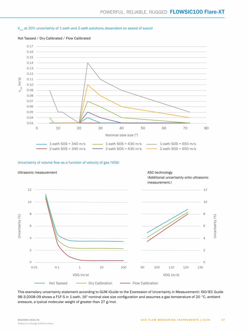
Vmin at 20% uncertainty of 1-path and 2-path solutions dependent on speed of sound
Hot Tapped / Dry Calibrated / Flow Calibrated
0.04
0.05
0.06
0.07
0 10 20 30 40 50 60 70 80
0.08
0.03
v min in
m/s
Nominal pipe size in ″
0.09
0.10
0.11
0.12
0.13
0.14
0.15
0.16
0.17
1-path sos = 340 m/s 1-path sos = 450 m/s 1-path sos = 650 m/s2-path sos = 340 m/s 2-path sos = 450 m/s 2-path sos = 650 m/s
Uncertainty of volume flow as a function of velocity of gas (VOG)
Ultrasonic measurement ASC-technology (Additional uncertainty onto ultrasonic measurement.)
2
4
6
8
10
12
0.01 0.1 1 10 100
0
Unce
rtai
nty
[%]
vog [m/s]
2
4
6
8
10
12
090 100 110 120 130
Unce
rtai
nty
[%]
vog [m/s]
Hot Tapped Dry Calibration Flow Calibration
This exemplary uncertainty statement according to GUM (Guide to the Expression of Uncertainty in Measurement): ISO/IEC Guide 98-3:2008-09 shows a F1F-S in 1-path, 16" nominal pipe size configuration and assumes a gas temperature of 20 °C, ambient pressure, a typical molecular weight of greater than 27 g/mol.
G A S F L O W M E A S U R I N G I N S T R U M E N T S | S I C K8023684/2021-03Subject to change without notice
1 7
POWERFUL. RELIABLE. RUGGED FLOWSIC100 Flare-XTv m
in [m
/s]
Nominal pipe size ["]
2-path SOS = 340 m/s1-path SOS = 340 m/s
2-path SOS = 430 m/s1-path SOS = 430 m/s
2-path SOS = 650 m/s1-path SOS = 650 m/s
Unce
rtai
nty
[%]
VOG [m/s]
Hot Tapped
VOG [m/s]
Dry Calibration Flow Calibration
Unce
rtai
nty
[%]
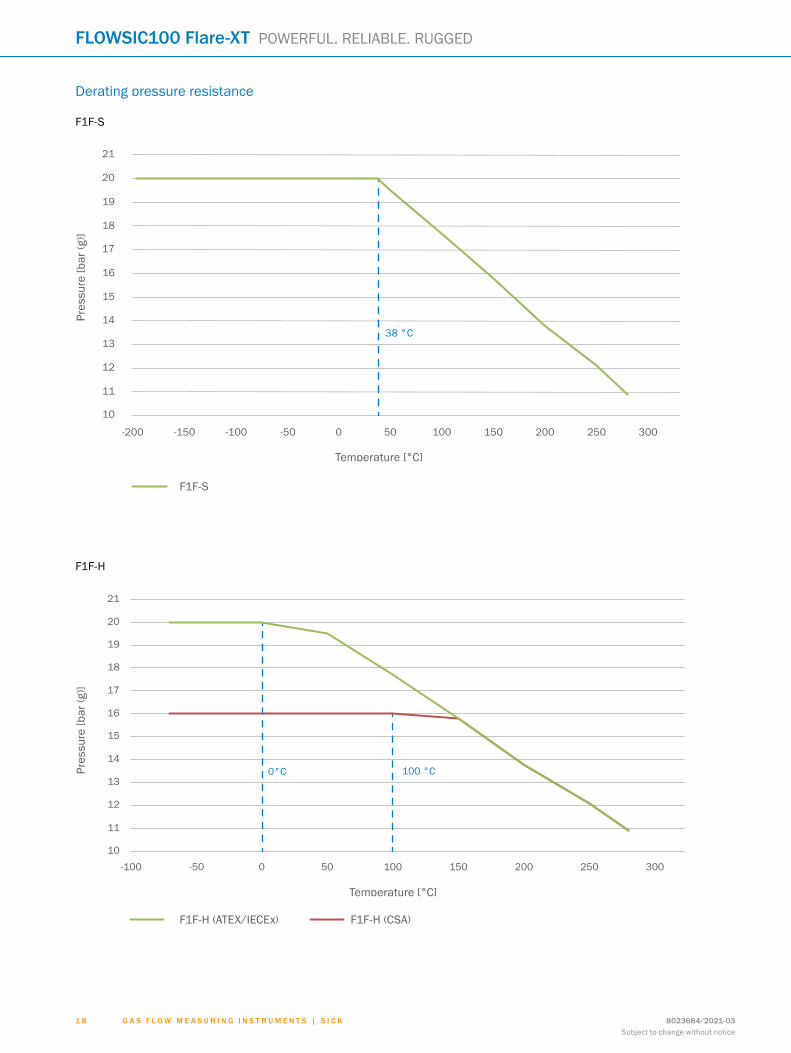
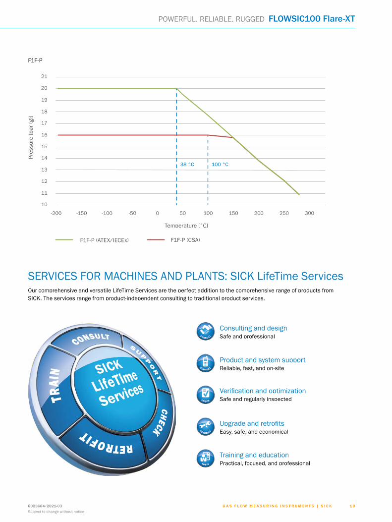
Derating pressure resistance
F1F-H
11
12
13
14
15
16
-100 -50 0 50 100 200 25010
Pres
sure
[bar
(g)]
Temperature [°C]
17
150 300
18
19
20
21
F1F-H (ATEX) F1F-H (CSA)
0°C 100 °C
F1F-S
11
12
14
15
16
17
-200 -150 -100 -50 50 100 150
10
Pres
sure
[bar
(g)]
Temperature [°C]
200 250
13
0 300
18
19
20
21
38 °C
F1F-P (CSA)
G A S F L O W M E A S U R I N G I N S T R U M E N T S | S I C K 8023684/2021-03Subject to change without notice
1 8
FLOWSIC100 Flare-XT POWERFUL. RELIABLE. RUGGED
Pres
sure
[bar
(g)]
Temperature [°C]
F1F-H (ATEX/IECEx) F1F-H (CSA)
Pres
sure
[bar
(g)]
Temperature [°C]
F1F-S
11
12
14
15
16
17
-200 -150 -100 -50 50 100 150
10
Pres
sure
[bar
(g)]
Temperature [°C]
200 250
13
0 300
18
19
20
21
38 °C
F1F-P (ATEX)
100 °C
F1F-P (CSA)
F1F-P
Pres
sure
[bar
(g)]
Temperature [°C]
F1F-P (ATEX/IECEx) F1F-P (CSA)
G A S F L O W M E A S U R I N G I N S T R U M E N T S | S I C K8023684/2021-03Subject to change without notice
1 9
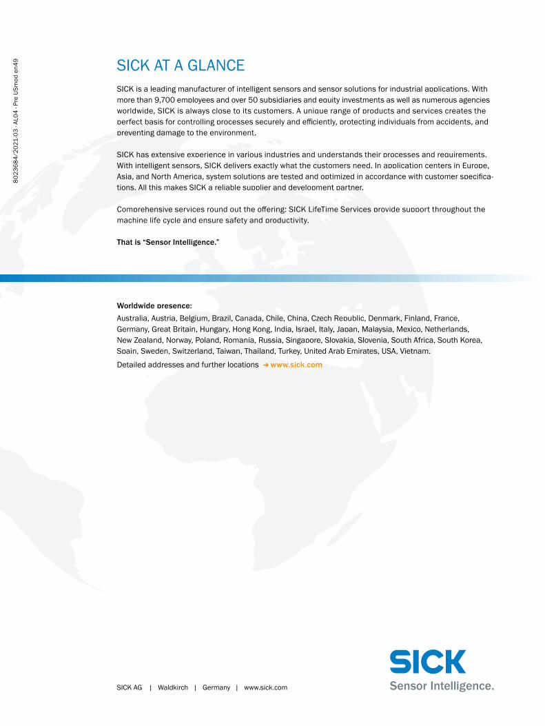
SERVICES FOR MACHINES AND PLANTS: SICK LifeTime ServicesOur comprehensive and versatile LifeTime Services are the perfect addition to the comprehensive range of products from SICK. The services range from product-independent consulting to traditional product services.
Training and educationPractical, focused, and professional
Upgrade and retrofitsEasy, safe, and economical
Consulting and designSafe and professional
Verification and optimizationSafe and regularly inspected
Product and system supportReliable, fast, and on-site
POWERFUL. RELIABLE. RUGGED FLOWSIC100 Flare-XT
SICK AG | Waldkirch | Germany | www.sick.com
SICK AT A GLANCESICK is a leading manufacturer of intelligent sensors and sensor solutions for industrial applications. With more than 9,700 employees and over 50 subsidiaries and equity investments as well as numerous agencies worldwide, SICK is always close to its customers. A unique range of products and services creates the perfect basis for controlling processes securely and efficiently, protecting individuals from accidents, and preventing damage to the environment.
SICK has extensive experience in various industries and understands their processes and requirements. With intelligent sensors, SICK delivers exactly what the customers need. In application centers in Europe, Asia, and North America, system solutions are tested and optimized in accordance with customer specifica-tions. All this makes SICK a reliable supplier and development partner.
Comprehensive services round out the offering: SICK LifeTime Services provide support throughout the machine life cycle and ensure safety and productivity.
That is “Sensor Intelligence.”
Worldwide presence:Australia, Austria, Belgium, Brazil, Canada, Chile, China, Czech Republic, Denmark, Finland, France, Germany, Great Britain, Hungary, Hong Kong, India, Israel, Italy, Japan, Malaysia, Mexico, Netherlands, New Zealand, Norway, Poland, Romania, Russia, Singapore, Slovakia, Slovenia, South Africa, South Korea, Spain, Sweden, Switzerland, Taiwan, Thailand, Turkey, United Arab Emirates, USA, Vietnam.
Detailed addresses and further locations - www.sick.com
8023
684/
2021
-03
∙ AL0
4 ∙ P
re U
Smod
en4
9