Embed Size (px)
Citation preview
Sponsored by:
Session 1: Grounding & Bonding Practical SolutionsFebruary 10, 2021
Powering and Grounding Implications for Small CellsRohit Narayan
nVent

Sponsored by:
Session 1: Grounding & Bonding Practical SolutionsFebruary 10, 2021
1. Modelling of ground resistance values carried out on WingIGSsoftware by Andrew Ritosa, Electrical Engineer nVent.
2. Selection of type of ground electrode systems suited for small cell assisted by Matthew Caie, VP at nVent.
3. Suggestion for types of power systems and ground electrodes by John Fischer, Principal Network Engineer at AT&T and Mario Spina, Principal Engineer DC Power and Grounding at Verizon Wireless
Credits

Sponsored by:
Session 1: Grounding & Bonding Practical SolutionsFebruary 10, 2021
1. Satheesh Hariharan, Product Manager Alpha Technologies , “Is remote line power ready for routine deployment” Intelec 2017.
2.5G Americas and Small Cell Forum “Small cell challenges & recommendations”, August 2018
3.“HFC Powering”, © 2009 Bentley Systems, Incorporated
4. James Blanc, Pedestal Networks Inc., Line Powering in the RemoteDSLAM World 12.07.04
Key References

Powering and Grounding Implications for Small Cells used in 4G And 5G Networks
• Over the past few years, deployment of small cells has shifted in focus from coverage to large-scale densification.
• The attractiveness of this technology from a data network availability point of view is obvious. However, considerations for powering and grounding of these small cells continue to be a challenge for the industry.
• This paper will look at options for powering and grounding of these facilities.

We will look at:
• Utility AC powered, metered and unmetered,
• Remote line-powering and cluster powering
• HFC powering
• Local -48V DC power without back up
• Local -48V DC power with back up
•Solar photovoltaic power

AC UTILITY POWERED
METERED & UNMETERED
• Two types of utility powered solution for small cells are being deployed for small cells today, metered and unmetered. The powering and grounding challenges for metered and unmetered small cells are essentially the same.
AC IN

AC UTILITY POWER
ADVANTAGES
• The obvious benefit is that AC power is the most readily available power source on city streets.
• Additionally, there is no remote power source to manage, no cabling required from site to site and in most cases
• AC powered solutions can be rapidly deployed.
DISADVANTAGES
• The primary disadvantage of an AC powered site is that there is no backup power in the case of an AC main failure.
• At the same time, sensitive equipment is more susceptible to damage from surges in power lines.
• There is a clear need to provide local grounding to this type of facility to both ensure public safety, to protect the network infrastructure and to provide noise control.

DC LINE POWERED• Line powering is another powering solution that is being
explored by many cellular carriers, mainly for widespread use throughout Canada and the United States.
• In this scenario, a -48Volt DC power system resides in a central office or other remote premises where the power is converted up to +/-190VDC resulting in a 380VDC line-to-line voltage at the supply end. This voltage is fed via twisted pair copper wires up to the small cell. Multiple twisted wires can be used in parallel to obtain a higher current rating.
• The higher DC voltage can be transmitted for longer distances without losses. At the load end, close to the small cell, the voltage is converted back to 48VDC to supply the equipment.
• Thus far, DC line powering has predominantly focused on Digital Subscriber Line Access Multiplexer (DSLAM) network devices where the required copper wiring already exists. But its application can be extended to powering small cells.

DC LINE POWERED
• There is no reliance on local AC power and associated installation costs.
• The DC system has a large backup battery (often 4–10 hours) at the central office.
• Allows use of existing copper wire infrastructure (previously used for fixed wire phones/ADSL).
• The power can be transmitted locally to other nearby cells.
DISADVANTAGES • May not have existing copper wire infrastructure or where
infrastructure does exist, the wire insulation and conductor may be in poor condition.
• There may be inadequate/missing records of cable pairs due to declining emphasis on telephone line copper wire maintenance.
• There may be limits on the amount of power being transmitted, however, this can be overcome by using multiple wire pairs (in general, small cells have relatively low powering requirements).
• There may be industry concerns about 380VDC present in phone wires. Typically, these concerns are mitigated by safety features built into the line powering equipment (using a ground fault interrupter circuit)
• Due to line resistance, attention must also be paid to power transfer curves,
• Attention needs to be paid to the voltage drop on the copper lines and the minimum gauge or number of wires used. It makes sense for carriers to have guidelines on what the lowest permissible output voltage
ADVANTAGES
DC LINE POWER – 2 WAYS
• The traditional approach whereby the centralized DC power system will be located at the nearest central office, exchange or mobile switching centre. Due to the challenges in ensuring integrity of the cable system users may not find this attractive for small cells whereby phone wires do not connect to the small cell for any other reason .
• Newer approaches have been seen, whereby the centralized power system with the backup battery is in a street cabinet and powers a cluster of small cells using existing copper cables or copper cables installed specifically for this purpose. This method is viable only in a densely populated area.

DISTRIBUTED POWERING VIA HFC
• In a recent white paper titled “Small cell siting challenges and recommendations,” 5G Americas and Small Cell Forum outline distributed cluster powering arrangements via Hybrid Fiber Coax (HFC):
• This paper cites that “In very dense environments, HFC can be used to deliver power and connectivity from a central location to a cluster of neighboring small cells. A suitable centralized location could be anywhere that has access to power and the optical network, such as an outdoor distribution cabinet, telecom closet or macro base station location.”

HFC CLUSTER POWERING
ADVANTAGES • HFC makes it possible to power and connect dozens of
small cell locations—spaced 200 meters apart—from a single location with local grid power and room for power backup.
• This also cuts out the time and cost of a utility drop.”
• There is no need to connect each small cell to AC power.
• is some battery backup capacity in the outdoor distribution cabinet (typically a few hours).
• There is low exposure to power surges and transients if surge protection is appropriately chosen for the outdoor distribution cabinet.
DISADVANTAGES
• The fundamental disadvantage of this powering method is that it is limited to small areas with very dense networks.

DC POWERED WITH BATTERY BACKUP
• For installations which have multiple small cells on one pole, the power can also be provided by installing a pole mounted cabinet housing a rectifier and batteries to power the small cells.
• This is arguably the most reliable means of providing backup power to the equipment without the need to transport the power from a remote locations.
DC POWERED WITH BATTERY BACKUP
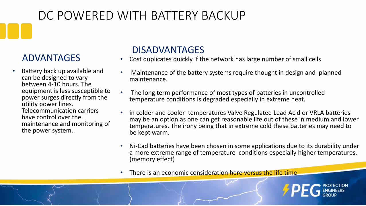
ADVANTAGES • Battery back up available and
can be designed to vary between 4-10 hours. The equipment is less susceptible to power surges directly from the utility power lines. Telecommunication carriers have control over the maintenance and monitoring of the power system..
DISADVANTAGES• Cost duplicates quickly if the network has large number of small cells
• Maintenance of the battery systems require thought in design and planned maintenance.
• The long term performance of most types of batteries in uncontrolled temperature conditions is degraded especially in extreme heat.
• in colder and cooler temperatures Valve Regulated Lead Acid or VRLA batteries may be an option as one can get reasonable life out of these in medium and lower temperatures. The irony being that in extreme cold these batteries may need to be kept warm.
• Ni-Cad batteries have been chosen in some applications due to its durability under a more extreme range of temperature conditions especially higher temperatures. (memory effect)
• There is an economic consideration here versus the life time

DC POWERED WITH NO BACKUP
Another method or powering that has beendeployed is whereby a -48VDC DC Power supplyis used without battery back up. Theadvantages of these are that the deployedequipment in the network can be consistentwith those used at DC powered sites andbatteries can be added at a later stage ifdesired.

SOLAR POWERING
Power can also be provided by a local solar PV array having regulated voltages and a backup battery. This method may be employed in remote areas, in temporary installations and in dense city locations where the previously discussed powering solutions cannot be utilized for various reasons.

SOLAR POWERING
ADVANTAGES
• The greatest advantage of a solar Photovoltaic, PV system is that it can be readily deployed with no need for electrical connection to any reticulated power supply.solutionscan be rapidly deployed.
DISADVANTAGES • The main disadvantages are that solar
panels require cleaning and charging and storage can be unpredictable depending on daylight conditions.
• For carriers, the presence of a battery backup system also means an added level of management.
• Maintaining hundreds of batteries along city streets where the temperature environment cannot be controlled can be costly and difficult.
TYPICAL GROUNDING METHODS
It can be seen that many of the powering methods discussed above will require alocal ground electrode near the small cell installation.
The purpose of this local ground electrode is to provide
• Public safety
• Low impedance ground for noise control
• A path for surge current dissipations from the power system
• Compliance to regulatory requirements
• Suitable AC and telecommunications equipment ground.

VERTICAL DRIVEN ELECTRODES• Vertical driven electrode are the least obtrusive on
the surface layers as they take very little footprint. However when utilizing these, the information available on buried services, near the electrodes needs to be known.
• The consequences of driving a deep driven electrode into an essential service like power cable of gas pipe could be catastrophic. Many countries have services and records like “call before you dig” to alleviate such risks.
• Vertical driven electrodes also provide an effective means of reducing the ground resistance. Multiple electrodes can be joined using earth rod couplers, say in 1.5m – 1.8m lengths to get greater depths of say 4.5m to 5.4m.

VERTICAL DRIVEN TRIANGLE FORMATION• Where space permits, the use of 3 vertical
electrodes in a triangle formation offers one of the best resistance values in comparison with other methods.
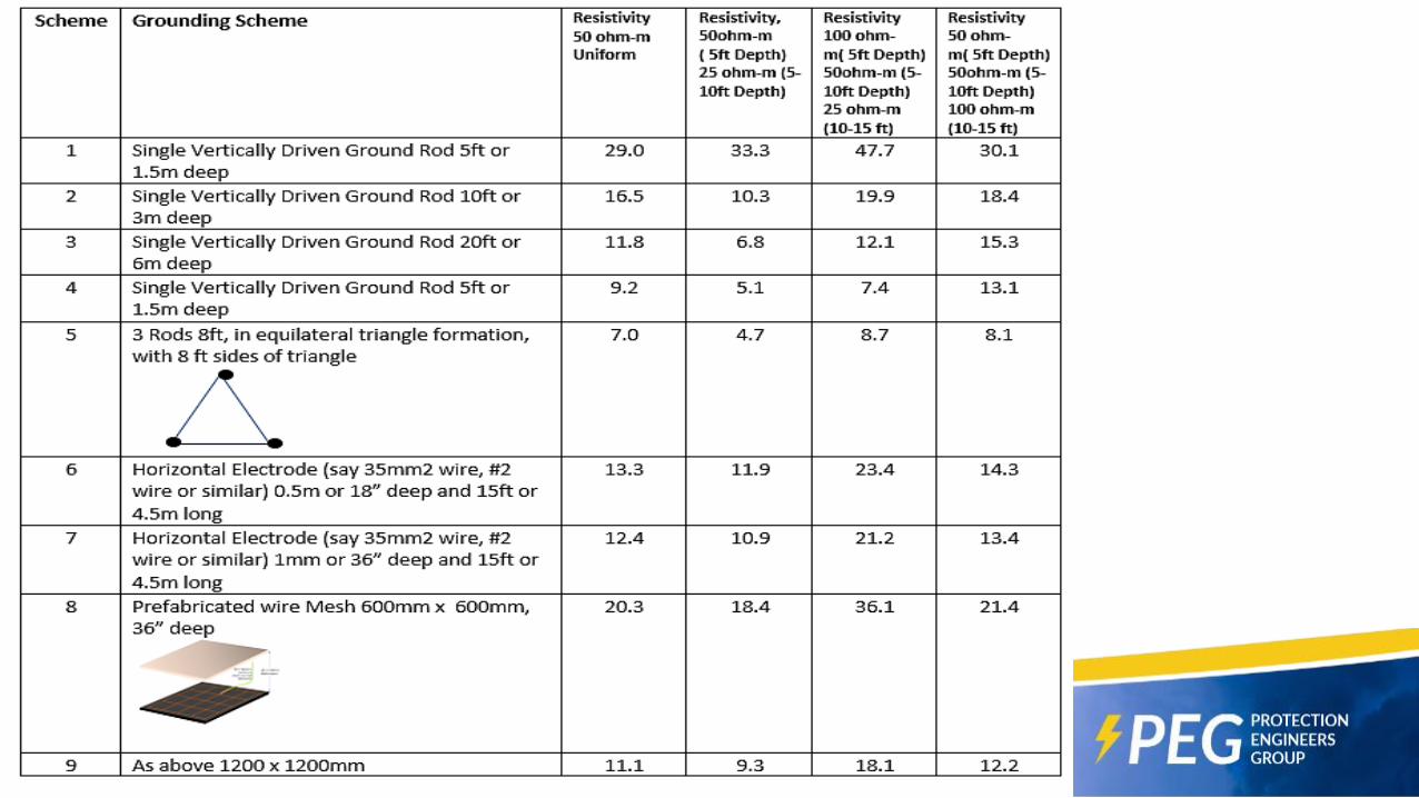
• The electrode depth would be in the range of 5ft. (1.5m) to 8ft (2.4m) long and the spacing between these would be one electrode space. Table 1 shows the resistance values of this type of electrode in comparison with other types discussed in this paper.
• The interconnecting conductors do not have a large impact on the resistance and the recommended size is between 35-50mm2.
• Theft deterrent conductors may be used in locations that are prone to copper theft .
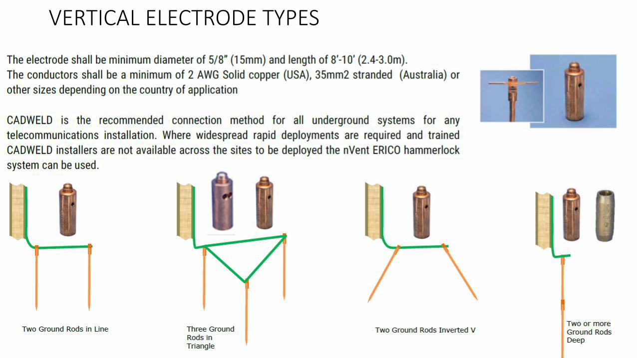
VERTICAL ELECTRODE TYPES

HORIZONTAL ELECTRODES• If there is micro-trenching or other
horizontal trenching done, to provide access or connectivity to the small cell via fiber or copper wires, then horizontal electrodes may be a viable option, provided these can be practically placed in the same trenches.
• For horizontal ground electrodes, the resistance improves with length of the electrode and less so with the depth.
• However the depth may be importance due to practicality of where the electrode could be laid, due to local legislation, due to mechanical considerations and in consideration of the freeze depth in very cold climates.

Mesh Electrodes • Mesh electrodes are suited where deep
driving and trenching is not possible and theequipment in mounted in a street cabinet,or there are existing pavers at the groundlevel.
• A 600mm x 600mm, 1200mm x 1200mm orlarger mesh of copper coated steel is usedin these applications. All joint within themesh is pre-welded and a pigtail can also bepre-welded. The mesh can be placed in 2inches of ground enhancement material likenVent ERICO GEM25A to provide furtherstability and consistency of groundresistance readings and low groundimpedance.

SUMMARY
• The deployment of small cells poses significant infrastructure challenges
• The powering and grounding of small cells is part of this infrastructure challenge
• Reliability of the small cell network is critical as more mission critical application will depend on it