Embed Size (px)
Citation preview

POWERLINK Basics
System Overview
PL_FLY_Basics_en_RZ_110315.indd 1 15.03.11 10:05

IT (Office, Internet)
Site level
Fieldbus technology Industrial Ethernet
Process level
Control level
Gateways FieldbusEthernet
IT (Office, Internet)StandardEthernet
IndustrialEthernet
Real-timeEthernet
+ + +
– + +
– – +
Why Real-time Industrial Ethernet?
Over the course of the last two decades, it has
become hard to keep track of the numerous field-
bus systems that have been developed in the auto-
mation industry specifically for purposes of process
and factory production control. Yet there remain
various restraints that are impeding their perform-
ance. Demand has therefore become more
pressing for a reliable communication system that
would offer high flexibility and across-the-board
compatibility. A new solution in this vein was also
expected to allow for ongoing improvements and
future upgrades. Ethernet first rose to that chal-
lenge: it was a tried and tested technology that
was free of patents and was widely standardized.
Moreover, it had great potential to serve as a
consistent, integrated communication solution, i.e.
allow for an interconnection of the control, process,
and field levels. However, standard Ethernet in
combination with an Internet protocol like TCP/IP is
unsuitable for data transmission in hard real-time.
Data traffic can be delayed in unforeseeable ways
due to the CSMA/CD mechanism (Carrier Sense
Multiple Access/Collision Detection). An integral
part of the Ethernet standard IEEE 802.3, that
mechanism helps prevent data collisions on the
bus that can occur in Ethernet environments due
to the particular nature of Ethernet transmissions.
In order to develop Ethernet-based, but real-time
capable fieldbuses, manufacturers have pursued
various approaches in their efforts to eliminate such
delays. These solutions are commonly referred to as
“Real-time Industrial Ethernet” technologies. This
booklet will introduce you to POWERLINK, which
has become one of the most successful Real-time
Industrial Ethernet systems in the world today.
2
PL_FLY_Basics_en_RZ_110315.indd 2 15.03.11 10:05

Contents I N T R O D U C T I O N | Application Areas
4 One Network for All Systems
5 Architectures, Performance Classes, Industry Sectors
T E C H N O L O G Y | How POWERLINK Works
6 The Mechanism
7 Performance
F E AT U R E S | Benefits in POWERLINK Networks
8 Topology
9 Unique Addressing
9 Hot Plugging
10 Direct Cross-Traffic
10 Multiplexing
11 Asynchronous Data
11 Poll Response Chaining
12 Redundancy
13 Diagnostics
14 openSAFETY
15 Security
16 CANopen
U S E R O R G A N I Z AT I O N | Ethernet POWERLINK Standardization Group
18 The User Organization EPSG
18 Standards
19 Conformance testing
19 POWERLINK Starter Kits
I M P L E M E N TAT I O N | How to POWERLINK-Enable Your Device
20 Master (Managing Node)
21 Slave (Controlled Node)
L O N G - T E R M V I A B I L I T Y | 22 Open Source Technology
23 Gigabit POWERLINK: Thinking about Tomorrow Today
POWERLINK Basics
3
PL_FLY_Basics_en_RZ_110315.indd 3 15.03.11 10:05
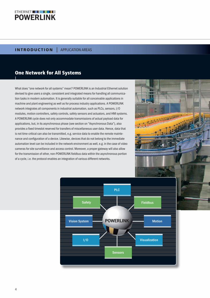
One Network for All Systems|
What does “one network for all systems” mean? POWERLINK is an Industrial Ethernet solution
devised to give users a single, consistent and integrated means for handling all communica-
tion tasks in modern automation. It is generally suitable for all conceivable applications in
machine and plant engineering as well as for process industry applications. A POWERLINK
network integrates all components in industrial automation, such as PLCs, sensors, I/O
modules, motion controllers, safety controls, safety sensors and actuators, and HMI systems.
A POWERLINK cycle does not only accommodate transmissions of actual payload data for
applications, but, in its asynchronous phase (see section on “Asynchronous Data”), also
provides a fixed timeslot reserved for transfers of miscellaneous user data. Hence, data that
is not time-critical can also be transmitted, e.g. service data to enable the remote mainte-
nance and configuration of a device. Likewise, devices that do not belong to the immediate
automation level can be included in the network environment as well, e.g. in the case of video
cameras for site surveillance and access control. Moreover, a proper gateway will also allow
for the transmission of other, non-POWERLINK fieldbus data within the asynchronous portion
of a cycle, i.e. the protocol enables an integration of various different networks.
POWERLINK
Safety
Vision System
I/O
PLC
Sensors
Fieldbus
Motion
Visualization
I N T R O D U C T I O N | APPLICATION AREAS
4
PL_FLY_Basics_en_RZ_110315.indd 4 15.03.11 10:05

ArchitecturesDue to its performance characteristics regarding bandwidth, brief cycle
times, and the protocol‘s flexibility, POWERLINK is suitable for both
centralized and decentral-style automation concepts. Machine and
plant designs featuring decentralized structures give users increased
flexibility for adaptations and extensions, but do require a commu-
nication system that lends itself well to such structures. POWERLINK
technology is particularly well suited to these requirements due to its
close adherence to the Ethernet standard, which yields two key features
for its use in decentralized environments: cross-traffic and a free choice
of network topology.
Cross-traffic enables direct cross-communications between compo-
nents that bypass the Master. All devices can send their data in broad-
cast mode directly into the network, where all other nodes can receive
these transmissions.
A free choice of topology is almost indispensable for modular system
extensions. Machine upgrades, plant expansions and ongoing additions
of new machinery to an installation are hardly possible at all, or only at
a great expense, in systems with fixed topologies. Not least due to its
excellent scalability, POWERLINK places no limits on system extensions
with no negative effects on the network‘s real-time capability.
Performance ClassesPOWERLINK covers all performance classes – as a software solution
with no hardware acceleration for soft real-time performance, or as a
high-end system featuring co-processor support for cycle times in the
area of only a few hundred microseconds. Since POWERLINK is patent-
free and solely based on standard hardware, various manufacturers
provide cost-optimized solutions for hard real-time applications.
Industry SectorsGiven its scalability and its capability to integrate all systems,
POWERLINK is used in machine and plant engineering, in process
automation, and for measuring technology.
Architectures, Performance Classes, Industry Sectors|
� Automotive
� Mining
� Chemical
� Printing and paper
� Energy
� Food and beverage
� Semiconductor
� Timber
� Plastics
� Logistics
� Maritime
� Metals
� Pharmaceutical
� Process
� Textile
� Transport
� Packaging
POWERLINK Basics
5
PL_FLY_Basics_en_RZ_110315.indd 5 15.03.11 10:05

The Mechanism|
Unlike other Real-time Industrial Ethernet systems, POWERLINK is a
purely software-based solution that is 100% in line with the IEEE 802.3
Ethernet standard. Providing close compliance to the standard and
doing without any proprietary hardware, POWERLINK ensures that all
benefits and the flexibility of Ethernet technology carry over to the real-
time protocol. Users are therefore able to draw on the same standard-
ized hardware components and use the same tools for diagnostics. In
order to achieve real-time capability, POWERLINK resorts to a mixed
polling and timeslot procedure that only allows one node at a time to
send data. Generally speaking, communication proceeds as it does
in an organized roundtable conversation, where a moderator prompts
participants to make their statements. In this scenario, the moderator
sees to it that everyone gets a turn to get a word in by explicitly inviting
one participant after the other to speak at a specific time. In contrast to
standard Ethernet, this procedure ensures that nodes cannot “speak”
at the same time. Hence, no arbitration is required either. POWERLINK
networks use the following communication structure: one node, e.g.
a PLC, motion controller, or industrial PC, is arbitrarily designated
to function as the so-called Managing Node (MN), i.e. serve as the
“moderator of the conversation.”
All other devices operate as Controlled Nodes (CN). The MN defines
the clock pulse for the synchronization of all devices and manages
the data communication cycle. In the course of one cycle, the MN
successively polls each CN. This polling is done via PollRequest
message, which additionally convey data from MN to polled CN. Each
CN then sends its own data to all other nodes via PollResponse
message. A POWERLINK cycle consists of three periods. During the
“Start Period,” the MN sends a “Start of Cycle Frame” (SoC) to all CNs
to synchronize the devices. Payload data exchange then proceeds in
the second period, the isochronous phase. The third period of a cycle
marks the beginning of the asynchronous phase, which allows for the
transfer not time-critical data packets, e.g. TCP/IP, parameterization
data …
T E C H N O L O G Y | HOW POWERLINK WORKS
6
PL_FLY_Basics_en_RZ_110315.indd 6 15.03.11 10:05

Performance|
MN
CN
IsochronousPhase
AsynchronousPhase
SoASoC
Async Data
PReqCN1
CycleTime
PReqCN2
PReqCN3
PResCN1
PResCN2
PResCN3
PReqCNn
PResCNn
� 0.1 �s system synchronization
� 100 �s cycle time
� 100 Mbit/s bandwidth
� high data throughput even for brief cycles
� 240 nodes e.g. 480 synchronized axes/460,000 digital channels
� 100 m/2 km line length between nodes
POWERLINK Basics
7
PL_FLY_Basics_en_RZ_110315.indd 7 15.03.11 10:05

Topology|
One of Ethernet’s – and therefore, also POWERLINK’s – most important
characteristics is that users are one hundred percent free to choose any
type of network topology. Networks may have a star, tree, daisy chain,
or ring structure, or any combination of these topologies, and need no
configuration. There is also no binding interdependence between logical
links in the application and the physical layout. Changes to the network,
including live modifications, can be made at any time and in any way
without compromising the application.
F E AT U R E S | BENEFITS IN POWERLINK NETWORKS
8
PL_FLY_Basics_en_RZ_110315.indd 8 15.03.11 10:05

Unique addresses can be set using a built-in, manually operated node
switch at every individual device, ensuring a transparent assignment of
IP addresses to the devices. This addressing method allows for simple
software configuration when setting up a network, and is indispensable
for reliable service. Unique addressing is a key prerequisite particularly
for machines featuring a modular design devised to enable quick and
easy extensions.
Hot plugging means plugging nodes in or disconnecting them from a
network line without
– compromising network functionality,
– having to reboot for added or replaced nodes to become operational.
POWERLINK provides unrestricted support for hot plugging. Extensions
or local replacements of devices do not impair real-time performance,
and no reboot of the system is required. Operators may therefore e.g.
exchange sensors or add mechatronic units without having to shut
down the network first – a basic precondition for using the protocol in
the process industry or in modular machines and plants.
Hot Plugging |
Unique Addressing|
POWERLINK Basics
9
PL_FLY_Basics_en_RZ_110315.indd 9 15.03.11 10:05

����������� �����|
Multiplexing|
MN
CN
B r o a d c a s t M e c h a n i s m
SoASoC
Async Data
SoC = Start of Cycle
SoA = Start of Async
PRq = Poll Request
PRs = Poll Response
MN = Managing Node
CN = Controlled Node
PReqCN1
PResCN1
PReqCN2
PResCN2
PReqCN3
PResCN3
PReqCNn
PResCNn
Every cycle: 1, 2, 3 Multiplexed: 4-11 8 data frames in 3 slots
1 2 3 4 5 6 A 1 2 3 7 8 9 A 1 2 3 10 11 A 1 2 3 4 5 6 A
Cycle i Cycle i+1 Cycle i+2 Cycle i+3
MN
CN
IsochronousPhase
AsynchronousPhase
SoASoC
Async Data
PReqCN1
PResCN1
PReqCN2
PResCN2
PReqCN3
PResCN3
PReqCN4
PResCN4
PReqCN5
PResCN5
PReqCN6
PResCN6
F E AT U R E S | BENEFITS IN POWERLINK NETWORKS
Multiplexing optimizes bandwidth use in the isochronous phase.
Since requirements regarding data sampling intervals vary from
application to application, not all Controlled Nodes have to be polled
in every cycle. While it is necessary e.g. for many motion control
applications to constantly provide drives with information, and to
poll their feedback data in every cycle, polling sensor data only once
every three cycles is sufficient for temperature measurement.
For multiplexing, Controlled Nodes with low priority data share a
timeslot within the isochronous phase, taking turns in such a way
that one device utilizes only the first, the second device only the
second, and the third device only the third cycle in every sequence
of three cycles to transfer their respective data. The MN assigns and
manages shared timeslots for such groups of nodes.
Ethernet communication – hence, of course, also POWERLINK com-
munication – works according to the broadcast scheme. This means
that every node is free to broadcast its own data into the network, and
every other node is generally able to receive these broadcasts. Nodes
can tell by the target addresses on data packets whether any such data
is intended for them. This send principle enables direct cross-traffic
among controllers, i.e. communication does not have to go through
a dedicated Master, or Managing Node. In synchronized production
segments, for instance, this feature enables a synchronization of the
rotary encoders on all drives with a master encoder. For decentralized
safety architectures, direct cross-traffic among safety components is a
basic prerequisite. Benefits lie in the time saved, the simplification of
the system, and the reduction of control tasks, which permits the use of
more economical controllers in many areas.
10
PL_FLY_Basics_en_RZ_110315.indd 10 15.03.11 10:05

The isochronous phase of the POWERLINK cycle for time-critical
payload data transfer is followed by the asynchronous phase that
takes up the rest of the cycle. In this period, not time-critical data
packets can be transmitted in standard Ethernet frames.
Data of any kind can be transmitted in the asynchronous phase:
Service Data Objects (SDO) for device configuration and diagnostics,
application data such as surveillance camera feeds, and also
protocols like TCP/IP for device configuration or maintenance from
a web browser. This is also a way to connect nodes that are not real-
time capable to the network, as well as a means to integrate compo-
nents or plant segments equipped with other fieldbus interfaces.
In the latter case, devices are hooked up to a POWERLINK node via
a gateway for this purpose, and their non-POWERLINK fieldbus data
is sent along in the asynchronous phase of the POWERLINK cycle.
This mode of data transfer is a crucial prerequisite for hot plugging –
newly added devices or replacements for others identify themselves
by sending their device data to the Managing Node in the
asynchronous phase.
POWERLINK protocol includes the “Poll Response Chaining” feature.
Instead of requesting the CNs sequentially through PReq frames,
the CNs are requested altogether by the PResMN frame which is sent
as multicast. This increases performance if many nodes with small
amount of process data are connected.
This feature is ideal for centralized control modes such as robot
applications with a centrally closed velocity or current control loop.
Asynchronous Data|
MN
CN
IsochronousPhase
AsynchronousPhase
SoASoC
Async Data
PResMN
CycleTime
PResCN1
PResCN2
PResCN3
PReqCNn
PResCNn
PResCN4
Poll Response Chaining|
POWERLINK Basics
11
PL_FLY_Basics_en_RZ_110315.indd 11 15.03.11 10:05

Redundancy|
F E AT U R E S | BENEFITS IN POWERLINK NETWORKS
has two interface ports that support redundant operation.) When a line
failure is detected, the system switches from the failed to the redundant
data route within one cycle. This type of redundancy is typically used for
solutions exposed to considerable mechanical stress.
Complete medium redundancyCritical systems require high availability features including complete
medium redundancy.
With POWERLINK, this complete medium redundancy is achieved
thanks to two different physical networks. The same redundant
information is conveyed at the same time on both networks. In case
of network failure, the switch-over is instantaneous without any down-
time or reconfiguration. Each node is linked to both physical networks
via a Link Selector (LS).
POWERLINK enables an implementation of two types of redundancy:
medium redundancy and Master redundancy.
Ring RedundancyClassic ring redundancy is a simple and very economic option in
machine engineering. Applications are linked in the form of a ring; both
outer ends of the data line running through the network are connected
to the controller. (For this layout, one extra data cable suffices to turn
a daisy chain of applications into a ring, provided that the controller
Fully redundant architecture for high-availability systems
LS CN 1
LS CN 2
First Link Second Link
Cable break Switch-over to Backup link
CN 1
CN 2
AMN
LS
AMN
LS
SMN
LS
RMN RMN
Link Selector (LS)
PLCPLC
12
PL_FLY_Basics_en_RZ_110315.indd 12 15.03.11 10:05
Diagnostics|
Master RedundancyThe second type of redundancy is full Master, or Managing Node, redun-
dancy, which plays a key role for high-availability systems, and is used
for energy systems in the process industry. Master redundancy is based
on two or more redundant Managing Nodes at the top of the network
hierarchy. Only one of them serves as an active Managing Node, the
other(s) remain(s) on hot standby and act(s) as Controlled Nodes from
the active Managing Node’s point of view. The only difference between
a standby MN and a CN is that a standby MN continuously monitors all
network and CN functions, which ensures that it can assume the func-
tion of the active MN at any time without rebooting. In an emergency,
the POWERLINK Node ID 240, which is reserved for the MN, is trans-
ferred on the fly to the closest redundant MN. This redundancy model
allows for a wide range of topologies. In any case, all basic POWERLINK
characteristics like minimal reaction times, real-time synchronization
capability, high bandwidth, and simple diagnostics features continue to
be fully available.
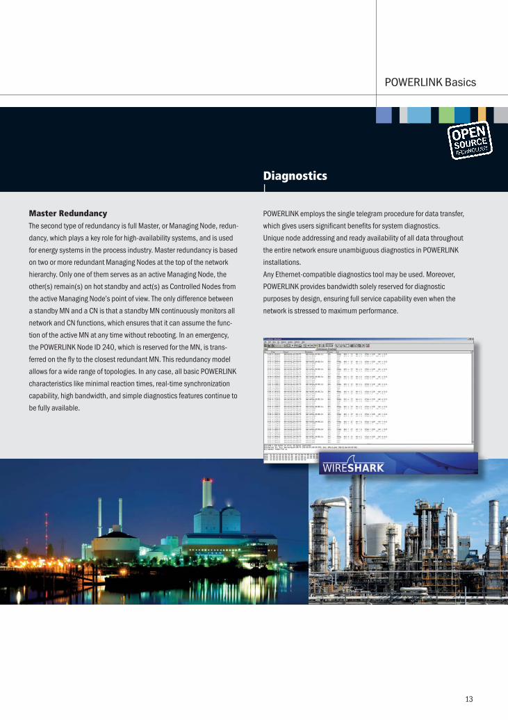
POWERLINK employs the single telegram procedure for data transfer,
which gives users significant benefits for system diagnostics.
Unique node addressing and ready availability of all data throughout
the entire network ensure unambiguous diagnostics in POWERLINK
installations.
Any Ethernet-compatible diagnostics tool may be used. Moreover,
POWERLINK provides bandwidth solely reserved for diagnostic
purposes by design, ensuring full service capability even when the
network is stressed to maximum performance.
POWERLINK Basics
13
PL_FLY_Basics_en_RZ_110315.indd 13 15.03.11 10:05

openSAFETY|
������������������������������������������������for all Industrial Ethernet solutions.End customers have been requesting a uniform and manufacturer
independent standard for years. With openSAFETY, the EPSG has
provided the response to those requests and introduced the world’s
first 100% open safety protocol. In fact, openSAFETY is open not only
in terms of its legal basis, but also literally open in technical respects:
given the protocol’s bus-independence, openSAFETY can be used
with all fieldbuses, Industrial Ethernet solutions, or industry-specific
communication solutions. Thanks to its real-time capabilities and
support of direct cross-communication, POWERLINK ideally
complements openSAFETY and ensures fastest safe reaction time
for safety systems.
The safety standard openSAFETY is certified SIL 3 according to
IEC61508 and it has been approved by IEC as worldwide safety
standard according to IEC 61784-3.
F E AT U R E S | BENEFITS IN POWERLINK NETWORKS
PROFINETEtherNet/IP�����SERCOSPOWERLINK
Machine 1 Machine 2 Machine 3 Machine 4 Machine 5
� ����������������� ��
� Benefits for end users
– a single, consistent safety standard for an
entire line or plant
– independence of control systems manufacturers
– perfectly suited to safe modular plant concepts
– minimal commissioning and retrofit time
– investment security though legal and
technical independence
� Benefits for manufacturers
– only one-time safety development required
– interoperability guaranteed
– reduced investment risk
– minimal time-to-market
– low costs due to open source
One safety standard
for the entire
production plant
14
PL_FLY_Basics_en_RZ_110315.indd 14 15.03.11 10:05

POWERLINK real-time domains are strictly separated from non-
real-time domains via gateways, which are often integrated into
the controllers.
Every POWERLINK network constitutes its own network domain that
is represented to the outside through one single IP address. The
gateways operate like a firewall in this set-up, and internally resolve
the public IP address via Network Address Translation (NAT) to the
invisible IP addresses of nodes in the real-time domain. Additional
security measures and filter rules can be defined and implemented
at the gateways as needed. Observing essential security aspects is a
basic design requirement for any safety system to be deployed.
Firewall/Gateway
Firewall/Gateway
Real-Time Domain Real-Time Domain Real-Time Domain
Non-Real-Time Domain
Security|
POWERLINK Basics
15
SIL3 certification by
TÜV Rheinland and TÜV Süd
PL_FLY_Basics_en_RZ_110315.indd 15 15.03.11 10:06

CANopen|
Joint Task ForceOne major decision made by the Ethernet POWERLINK Standardization
Group (EPSG) was to define the protocol’s application layer as a carrier
of all CANopen mechanisms. CAN in Automation (CiA), the international
association of CAN users and manufacturers, was significantly involved
in this development.
CANopen – the Most Widely Used Application ProtocolCANopen is one of the most widely used application protocols today.
Its key benefits include its standardized device description files, which
make status information, parameterizations, device characteristics,
and other relevant data transparently available on the network. Devices
POWERLINK and CANopen
� Joint Task Force
– common, consistent use of the CANopen profile
– XML Device Description
� CANopen over Ethernet
– long-term investment viability
– identical application access
– simple migration
– experienced service providers
� Benefits compared to CAN’s physical characteristics
– 100 times faster data transmission
– one medium for the entire machine
– line lengths up to 100 m
F E AT U R E S | BENEFITS IN POWERLINK NETWORKS
16
PL_FLY_Basics_en_RZ_110315.indd 16 15.03.11 10:06

from different manufacturers that share the same description file can
easily replace each other with no need for any reconfiguration.
POWERLINK = CANopen over EthernetPOWERLINK uses the same device description files as CANopen, the
same Object Dictionaries, and the same communication mechanisms,
such as Process Data Objects (PDO), Service Data Objects (SDO), and
Network Management (NMT). As with CANopen, direct cross-traffic is
also one of POWERLINK’s essential features. All CANopen applications
and device profiles can immediately be used in POWERLINK environ-
ments as well. Applications will not see a difference between the
protocols. POWERLINK can therefore also be referred to as “CANopen
over Ethernet.” Due to the CiA’s and EPSG’s close cooperation,
many well-known CANopen service providers on the market also offer
POWERLINK solutions and products today, which ensures that users
have a wide range of qualified services to choose from.
High Performance With CANopenApplication complexity is generally increasing, which leads to a greater
number of nodes, rising data load, and higher performance require-
ments. A simple migration to POWERLINK is an ideal alternative for
users who wish to continue to enjoy CANopen’s benefits in spite of
more demanding requirements. Moreover, POWERLINK gives them
one consistent medium throughout the entire application.
Ethernet ControllerHardware
OthersDevice Profiles
ProtocolSoftware
Ethernet Driver
POWERLINK Driver
UDP/IP
POWERLINK Transport
CANopenApplication Layer – Object Dictionary
Messaging (SDO and PDO)
I/O Encoders Valves Drives Medical
Can Driver
Can Controller
CAN basedCANopenTransport
POWERLINK Basics
17
PL_FLY_Basics_en_RZ_110315.indd 17 15.03.11 10:06

The User Organization EPSG|
Working Groups Office SalesRepresentatives
Supervisory Board
General Management
monitors the proper pursuit of the Association’s goals
elects
elects
GeneralAssembly
appointsCEO
appoints
Managing Director
U S E R O R G A N I Z AT I O N | ETHERNET POWERLINK STANDARDIZATION GROUP
� IEC 61784-2
� IEC 61784-3
� IEC 61158-300
� IEC 61158-400
� IEC 61158-500
� IEC 61158-600
� IEEE 802.3
� ISO 15745-1
Open AssociationBased in Switzerland, the Ethernet POWERLINK Standardization Group
is an independent registered association with a democratic charter.
Founded by drive and automation industry leaders in 2003, the EPSG’s
members pursue their common goal of standardizing and enhancing
POWERLINK technology. New members joining this organization have a
say in it right away and become, in a manner of speaking, “co-owners”
of this real-time Ethernet technology.
Open ProtocolThe protocol was introduced by B&R in 2001, followed by the open
release of the specification in 2003. A testament to the protocol’s
openness, the technology is free of any patents. Released under the
BSD license in 2008, the open source version openPOWERLINK is
available free of charge.
Open DevelopmentVarious working groups within the EPSG engage in continual improve-
ments to the technology in areas such as safety, technology design,
certification, user requests, and marketing and sales.
Open BasisPOWERLINK technology is developed based on open standards like
IEEE 802.3 (Standard Ethernet) and IEC 61784-2 (Real-time capable
Ethernet-based fieldbuses).
18
PL_FLY_Basics_en_RZ_110315.indd 18 15.03.11 10:06

Conformance testing|
The EPSG provides conformance testing and certification services.
The EPSG also regularly organizes plugfests, which are held on
various locations around the world.
Various manufacturers and service providers in the EPSG supply evalu-
ation boards (starter kits) that are ready to run right out of the box,
which make hardware testing for POWERLINK networks much simpler
for component and system manufacturers. Well-documented functions
and interfaces enable users or testers to focus exclusively on the inte-
gration of their device into the network environment. Due to onboard
integration of all key data communication functions, there is no need for
time-consuming programming or protocol stack ports. The full perform-
ance and all capabilities of the target device continue to be available.
Well-Tried TechnologyAs soon as the evaluation of a device’s functionality on a POWERLINK
network using a test board is successfully concluded, the device and
its interface are configured according to the specified requirements.
The easiest way to reduce the time-to-market is to resort to a reference
design, which is achieved by transferring the blueprint of an evaluation
board’s circuitry to a target device and integrating it into it. Soft- and
hardware suppliers in the EPSG provide various license models for this
purpose, permitting manufacturers to choose a 1:1 implementation of
a reference model as well as to use only portions of it. In either case,
reference designs are an ideal starting point for a quick and successful
POWERLINK implementation.
Broad Tool SupportA number of EPSG members offer designs and test tools for rapid
POWERLINK application development. Programs for device database
administration, for Object Dictionary, initialization code, and Electronic
Data Sheet generation in XML format serve to optimize development
processes and minimize the error rate. Tools for accurate network analy-
sis and real-time performance analysis complement this range.
POWERLINK Starter Kits|
POWERLINK Basics
19
PL_FLY_Basics_en_RZ_110315.indd 19 15.03.11 10:06

Technical Implementation for Master and Slave Devices|
I M P L E M E N TAT I O N | HOW TO POWERLINK-ENABLE YOUR DEVICE
Master (MN) Standard PC-Hardware
Linux
Others
Co-Processor Solution PCI Card
Windows
POW
ERLI
NK
FPGA Design
Embedded Design
Slave (CN) POWERLINK-only Slave
FPGA Technology
POWERLINK-only 32bit CPU
Multi-Protocol Slave
On Application Processor
On Application Processor
System on Chip
PCI Board
FPGA Technology
Communication Processor
POW
ERLI
NK
POWERLINK MasterPOWERLINK can be used without hardware support on any operating
system of choice, e.g. Windows, Linux, or VxWorks, with a standard
onboard Ethernet controller. The jitter and cycle times that can be
achieved are contingent on CPU performance and on an optimal
adaptation of the operating system to the CPU. Cycle times around
500 �s and jitter values of about 30 �s are typical. Integrating a
PCI card with a POWERLINK pre-implementation into the system is an
alternative option for a POWERLINK Master. In this case, a co-processor
handles the protocol stack and saves central processor resources,
typically achieving cycle times of 100 �s and an accuracy of .1 �s.
“How can I POWERLINK-enable my device?” is one of the questions
most frequently asked by manufacturers. POWERLINK can generally be
integrated into any standard embedded Ethernet design irrespective of
the choice of processor architecture, either as a pure software solution
or with hardware support. For pure software solutions, POWERLINK is
directly integrated on the application processor, and uses a standard
Ethernet controller as its bus connection. If very demanding require-
ments call for hardware acceleration, a number of manufacturers give
users a broad variety of options permitting them to implement solutions
tailored to their needs, all of which do not require any proprietary
technology such as ASICs. The illustration below provides an overview
of existing solutions.
20
PL_FLY_Basics_en_RZ_110315.indd 20 15.03.11 10:06

POWERLINK SlaveLikewise, POWERLINK Slaves can be implemented
as stacks on the application processor, or alter-
natively be based on dedicated communication
hardware. POWERLINK Slave implementation
types range from ready-to-run evaluation boards
or piggyback-style single boards, which are suit-
able for prototyping or for series manufacturing of
smaller lots, to optimized, FPGA-based chip solu-
tions complete with the protocol as well as the
application software. These various options differ
in terms of flexibility as well as cost. Multi-proto-
col solutions allow component manufacturers to
use a consistent hardware platform that is open
for various Industrial Ethernet solutions, and only
calls for a decision for a specific fieldbus when a product is customized
to be shipped to an end user. This option is usually more expensive than
dedicated POWERLINK-only solutions. Multi-protocol ASICs accommo-
date the entire system design in one chip. Benefits include the defined
interface between the communication processor and application
processor, but there are also drawbacks such as the fixed programming
interface, and higher hardware costs, or costs that vary with production
lots. Multi-protocol FPGA solutions provide flexibility for environments
where different protocols are used. In contrast to ASIC solutions, users
have an influence on the API. However, they should be aware that the
hardware costs are contingent on the resource requirements of the
most demanding protocol involved. POWERLINK-only FPGA solutions
provide more economic alternatives, and are flexible regarding the
interface. Conventional 32-bit CPUs equipped with internal RAM and
internal flash memory constitute the most cost-efficient option to con-
nect a Slave, clearly undercutting even the price range of other, ASIC-
based protocols, while still ensuring that users enjoy the flexibility and
openness of a standard microprocessor. A common characteristic of all
options is that they feature a flexible connection of the application and
communication software, e.g. via dual port RAM or a serial interface.
POWERLINK CNCommunication
Processor
Direct I/O
FPGA
POWERLINK CNCommunication
Processor
Application
Software API
FPGA
POWERLINK CNCommunication
Processor
Application
Software API
Microprozessor
FPGA
Simple I/O slave Integrated application Slave with external C
POWERLINK Basics
21
PL_FLY_Basics_en_RZ_110315.indd 21 15.03.11 10:06

L O N G - T E R M I N V E S T M E N T V I A B I L I T Y
XML – the New Device Description StandardStandardized device description files minimize the configuration effort
needed for networks with devices from different manufacturers. These
files enable consistent access from the Network Master to all relevant
device information, e.g. status data, device parameterization, or key
characteristics, regardless of device types and manufacturers. New
devices are immediately available on the network. POWERLINK uses
the new standard XML for its device description files. An XML-based
description format gives manufacturers the major advantage that they
can use a consistent, standardized description for different fieldbuses
or real-time Ethernet systems for their devices. Moreover, XML provides
a range of options for device descriptions that other languages have
failed to implement to date, including e.g. multi-language capability,
an option for textual descriptions, or parameter and value characteriza-
tions by physical units and scaling functions.
openPOWERLINKopenPOWERLINK is a complete protocol solution for Masters and
Slaves. Programmed in ANSI-C, the implementation can be easily
ported to any target system.
openPOWERLINK has been released on sourceforge under BSD
license. The BSD license grants permission to anyone to use,
distribute, modify and enhance the software free of charge. Anyone
may also integrate the software into retail products and source
code for custom modifications need not to be disclosed.
Detailed instructions for setting up a system and putting it into
operation are available at
www.sourceforge.net/projects/openpowerlink.
100 % open technologyThe EPSG does not levy any license fees for the technology. POWERLINK
is an open technology; customers can always choose among various
POWERLINK manufacturers and service providers, which ensures an
optimal price/performance ratio for every application. Whether time-
to-market or price is what matters most: the open software solution
featuring a consistent specification gives users greater freedom and
more opportunities for technical optimizations than other comparable
real-time Ethernet systems.
Open Source Technology|
22
PL_FLY_Basics_en_RZ_110315.indd 22 15.03.11 10:06

!�"�����#$&�'()*+�� ���2��"������ 3��4� ���|
1 GBit
2010
100 MBit10 MBit
20001990 2020
One glance at the world of automation reveals that bandwidth is not a
bottleneck for current real-time Ethernet systems. As of yet, 100 Mbit/s
do suffice completely. POWERLINK even provides enough capacity
for the most demanding applications, like Safe Motion Control for
machines with e.g. one hundred axes. However, a look back at the
course of development in automation makes one thing clear: data load
keeps rising, the number of drives per machine leaps up, and sensor
and actuator performance and capabilities are increasing. As this trend
continues, complexity and, by extension, data traffic are also mounting.
This ongoing development has already pushed the non-Ethernet-based
fieldbuses to their limits, and has eventually gave rise to Ethernet as
a replacement for fieldbus systems.
The integration of essential technologies is set to generate more
and more data load, e.g. for safety. Extensive functionality delivers
more flexible solutions, while the amount of data surges at the same
time. Therefore, in the medium term, Gigabit Ethernet will become
the standard that replaces Fast Ethernet. With Gigabit POWERLINK
development already underway, POWERLINK is fully prepared for the
future. POWERLINK’s inventors were determined to create a real-time
capable system based on standard Ethernet that draws on that
medium’s ongoing enhancement, and puts it to use in automation
technology: that is the reason why POWERLINK keeps absolutely close
to the standard and is solely software-based. In addition, the real-time
protocol uses the CANopen application interface that is completely
independent of the underlying transport protocol. A migration to Gigabit
technology will therefore not change the application interface in any
way, which will ensure full compatibility to the application – the key
factor for the long-term viability of investments in this technology.
The advent of Gigabit technology in the consumer world currently results
in a shift in hardware pricing for manufacturers: Gigabit equipment is
becoming less expensive, while, in the medium term, Fast Ethernet
hardware will become more expensive due to decreasing production
lots. POWERLINK’s standard compliance makes it ideally suited for
Gigabit Ethernet. With up to a factor 20 speed increase, the migration
to Gigabit POWERLINK opens up a new dimension of performance in
Industrial Ethernet environments.
POWERLINK Basics
23
PL_FLY_Basics_en_RZ_110315.indd 23 15.03.11 10:06

POWERLINK OFFICE of the EPSGSchaperstraße 18
10719 Berlin · Germany
Phone: +49 . 30 . 85 08 85 - 29
Fax: +49 . 30 . 85 08 85 - 86
E-Mail: [email protected]
www.ethernet-powerlink.org
© E
PS
G 2
011
M
M-E
011
06
.87
3
PL_FLY_Basics_en_RZ_110315.indd 24 15.03.11 10:06