Embed Size (px)
Citation preview

PowerPanel50 External Wall
SystemDESIGN AND INSTALLATION GUIDE
NEW ZEALAND

PowerPanel50 External Wall System 2

3PowerPanel50 External Wall System
Contents
Disclaimer: The photographs of houses included in this guide, while built from Hebel AAC panels, may not be constructed with the PowerPanel50 system.
Introduction 4
1. Design and selection details 7
1.1. Designing a External Wall 7
1.2. Structural provisions 8
1.3. Design and detailing considerations 13
1.4. System components 15
2. System performance 17
2.1. Durability 17
2.2. Fire resistance performance 18
2.3. Energy efficiency 23
2.4. Sound transmission and insulation 26
2.5. Coating requirements 27
2.6. Weatherproofing 29
3. Installation detail 30
3.1. Hebel PowerPanel50 installation sequence 30
3.2. Tools and equipment for construction 31
3.3. Installation of services 31
3.4. Construction details – Hebel PowerPanel50 32
4. Handling, storage and responsibility 54
4.1. Delivery and storage 54
4.2. Panel handling 55
4.3. Design detailing and performance responsibilities 56
Appendices 57
Appendix A: PowerPanel50 material properties 57
Appendix B: Architectural specification 58
Appendix C: Checklists 59
Appendix D: System Descriptions 61
PowerPanel50
External Wall System
Design and Installation Guide
This Design Guide has been prepared as a source of information to provide general guidance to consultants. It does not replace the services of the professional consultant and relevant engineers designing the project. It is the responsibility of the architectural designer and engineering parties to ensure that the details in this Design and Installation Guide are appropriate for the intended application. The recommendations of this guide are formulated along the lines of good building practice, but are not intended to be an exhaustive statement of all relevant data.
CM20222CM20243

4 PowerPanel50 External Wall System
Better homes are built with Hebel
Hebel is an Autoclaved Aerated Concrete (AAC) available as blocks and lightweight steel reinforced concrete panels. Hebel has been used in Europe for over 70 years and here in New Zealand for over 20 years.
Hebel reduces your total cost to build. Hebel is a unique high performance masonry system that is easy to install and speeds up construction time. The Hebel system can be installed without bricklayers and reduces the requirement for skilled trades-people on site. Whether you choose to install it yourself using existing trades or have it supplied and installed by readily available and experienced crews you will be happy with the cost savings.
Homeowners love its design and sustainability The Hebel PowerPanel50 External Wall System provides an attractive, modern exterior with a huge choice of rendered finishes and colours for a contemporary and aspirational look that new home buyers are looking for. But it’s not just popular for its looks. Hebel provides a low mass cladding solution which is also highly fire resistant and has excellent acoustic and thermal insulation properties that contribute to higher energy efficiency and reduced heating and cooling costs.
Made and distributed by CSR Hebel is manufactured in Australia to the highest quality standards and our warranty is backed by CSR, one of Australia’s oldest companies, for your peace of mind. Hebel is distributed in New Zealand by CSR Hebel, a division of CSR Building Products (NZ) Ltd, a wholly owned subsidiary of CSR in Australia and our systems have been developed in New Zealand to meet local requirements so you can rely on New Zealand and Australian expertise and stock holdings.

5PowerPanel50 External Wall System
Hebel PowerPanel50. Better to build with...
Faster construction period
Hebel PowerPanel50 is faster to install than other 50mm AAC cladding systems and requires significantly less labour than traditional masonry construction methods, leading to substantial savings in site costs. Building with Hebel also means a cleaner, safer construction site and less clean-up at completion.
Solid as brick but lighter in weight
Hebel PowerPanel50 panels are made from lightweight steel reinforced concrete so they are built to be solid. At about 1/3 the weight of bricks, the PowerPanel50 External Wall System provides an excellent solution for areas that are seismically active or have poor ground conditions. Once finished the PowerPanel50 External Wall System is almost impossible to tell apart from a rendered brick wall.
A comfortable living environment
Hebel’s unique aeration provides superior insulation properties for a masonry product. The unique combination of thermal resistance along with thermal mass, make building with Hebel a smart choice for meeting New Zealand’s building energy efficiency regulations. For unit and homeowners, the result is a more comfortable home with lower heating and cooling costs.
Fire resistant for peace of mind
Hebel is non-combustible and renowned for its fire resistance properties. The PowerPanel50 External Wall System has been assessed by BRANZ. See Fire section of this guide for further information.
A sound reason for better acoustics
Hebel pioneered the introduction of lightweight wall panels to provide excellent acoustic performance. The PowerPanel50 External Wall System has been assessed to achieve acoustic performance up to Rw + Ctr = 39 (STC = 45).
Sustainability for a better world
Environmentally friendly, Hebel products and systems are the sustainable choice. Independent testing shows that overall Hebel has a 30% lower environmental impact than concrete or brick veneer. Using over 60% less embodied energy, and producing at least 55% less greenhouse emissions than concrete or brick veneer, Hebel is the cleaner, greener choice.
At the heart of the Hebel residential external wall system is the Hebel PowerPanel50 - a 50mm thick, steel reinforced building panel made from AAC (Autoclaved Aerated Concrete) supplied in lengths of 2200mm to 3000mm with standard width of 600mm.

6 PowerPanel50 External Wall System
Hebel PowerPanel50 is the more efficient way to build
The Hebel PowerPanel50 External Wall SystemThe Hebel PowerPanel50 External Wall System has been designed for homes built using either timber or steel framing including home extensions or re-cladding of existing homes. The system consists of 50mm thick, lightweight, steel-reinforced Hebel PowerPanel50 panels, fixed vertically to horizontal battens attached to the load-bearing frame. For quick, clean construction, Hebel PowerPanel50 panels can be ordered in stock lengths of 2200mm, 2400mm, 2550mm, 2700mm and 3000mm and widths of 600mm.
The many applications of other Hebel productsIn addition to the widely accepted Hebel PowerPanel50, Hebel also manufactures a wide variety of building systems for floors and fencing plus load bearing blocks for external and Internal walls. For further information visit www.hebel.co.nz
Fig. 1.1 – Typical Home Construction Application
TIMBER OR STEEL FRAME
PERFORATED STEEL TOP HAT SECTION
HEBEL 50mm POWERPANEL50 PANELS
BUILDING WRAP (OR WALL UNDERLAY)
HEBEL ADHESIVE TO EDGE OF PANEL
DAMP-PROOF COURSE (DPC)
EXTERNAL COATING SYSTEM
CONTROL JOINT
FOUNDATIONS

7PowerPanel50 External Wall System
Fig. 1.2 – Flow Chart for Design Process
DETERMINE Wind category and earthquake zone
CONFIRM Stud capacity and spacing
ESTABLISH Panel height from architectural plans. Panel
base option – suspended or supported.
From the building designer, e.g. the project engineer or architectural designer
From the architectural designer
TABLE
• 1.5 – 1.10
• 1.5 – 1.10
• 1.4
DETERMINE
• Number of Top Hats
• Maximum Top Hat spacing
• Number of screws per panel per Top Hat
Design processThis section outlines the design process for determining the adequacy of Hebel PowerPanel50 External Wall System.
STEP 1: Determine the wind category, earthquake zone, stud framing layout and panel height requirements.
STEP 2: Design Criteria. Where required identify the NZBC Performance Requirements:
• Fire Resistance Level Rating (FRR).
• Sound insulation performance (Rw. Rw +Ctr, STC values).
• Energy Efficiency (R-Value).
STEP 3: The flowchart below can be used to select a type, spacing and quantity of Top Hats and fixings to suit requirements.
STEP 4: Select insulation and/or wall wrap material to suit energy efficiency and condensation requirements.
STEP 5: Check adequacy of sound insulation and fire resistance level.
STEP 6: Complete detailed design and documentation.
Compliance with the New Zealand Building Code (NZBC)In New Zealand, the building of houses and other buildings is controlled by the Building Act 2004. This applies to the construction of new buildings as well as the alteration of existing buildings. The Building Act 2004 requires that all building work comply with the New Zealand Building Code (NZBC), whether or not a building consent is required in respect of that building work. Where a building consent is required, this will be issued by a Building Consent Authority (BCA) once they have established that compliance with NZBC will be achieved with respect to the building work. One means of establishing compliance with NZBC is to achieve certification under the CodeMark Product Certification scheme which is
administered in New Zealand by the Ministry of Business Innovation and Employment (MBIE). CodeMark certificates have the same legal status as a compliance document and must be accepted by a BCA.
The Hebel PowerPanel50 External Wall System is compliant with the performance requirements of the New Zealand Building Code (NZBC) as evidenced by achieving CodeMark product certification.
The CodeMark certificate sets out which clauses of NZBC are being complied with along with any conditions or limitations that need to be applied. For the Hebel PowerPanel50 External Wall System, the following conditions and limitations apply:
1. To be designed and installed in accordance with the information provided in this design guide
2. All joinery used in conjunction with this Design and Installation Guide must meet the requirements of NZS 4211:2008
3. For use in Importance Level 1 & Importance Level 2 buildings, as defined in NZS 3604:2011, Table 1.1, up to and including three storeys high and situated in wind zones up to and including Extra High as determined in NZS 3604:2011
4. Where the building is situated in an Extra High wind zone or where the cladding system is used on an external wall frame without an internal lining, a rigid wall underlay shall be used.
5. For use as an external wall cladding on buildings where the wall face concerned has a building envelope risk matrix score of less than 20 as determined using NZBC E2/AS1 section 3.
6. The use of Hebel PowerPanel50 – 50mm External Wall System as a fire rated system, in whole or in part, is restricted to Buildings within risk group SH as defined by NZBC C/AS1 Clause 1.1.1
1.1 Designing an external wall

8 PowerPanel50 External Wall System
1.2 Structural provisions
ScopeThe Hebel PowerPanel50 External Wall System may be used in timber or steel framed buildings that are of Importance Level 1 or Importance Level 2, as defined in NZS 3604:2011, Table 1.1, up to and including three storeys high that are situated in:
• Wind zones up to and including Extra High as determined in NZS 3604:2011
• Earthquakes zones up to Zone 3 as defined in NZS 3604:2011
• Exposure Zones B, C & D as defined in NZS 3604:2011
OverviewThe Hebel PowerPanel50 External Wall System consists of Hebel PowerPanel50 panels secured to the framing via horizontal steel Top Hats. This section provides the basic information on the selection of Top Hat spacings for a given stud spacing and wind category, as well as considerations to assist the designer in determining the appropriate wall configuration.
The design information presented in Tables 1.4 to 1.10 has been determined with respect to the Hebel 24mm and 35mm Perforated Top Hat Section (Provisional Patent).
Please contact Hebel for information on other types or sizes of Top Hat sections. Minimum performance requirements for the Perforated Top Hats, fixings and Hebel PowerPanel50 panels have also been provided below to assist design if needed.
IMPORTANT: The design and approval of the structural framing (cold-formed steel or timber) is the responsibility of the project engineer or architectural designer.
Principles of designThe principles on which the design is based include:
a) The lateral wind loads or seismic loads (whichever is the greater) applied to the panels are transferred into the horizontal Top Hats, then to the stud frame, which should be designed in accordance with the requirements of the relevant New Zealand Standard or NZBC cited documents for the imposed loads. The frame should be designed for all bracing and hold-down requirements.
b) The design of the stud frame shall consider the weight of the suspended panels (such as the upper storey of two-storey construction). Note that with the approximate combined mass of less than 40kg/m2 the Hebel PowerPanel50 External Wall System is considered to fall within the medium weight cladding classification (less than 80kg/m2 as defined by NZS3604:2011).
c) The system is considered to be a ‘face-sealed’ cavity construction cladding system, where the cavity exists as a secondary defence mechanism against any water ingress, should it occur. Any water ingress will drain within the cavity, or migrate through increased atmospheric moisture content, to the back face of the Hebel panel which will absorb the moisture and expel it through the vapour permeable water resistant plaster coating system. As shown in this design guide there is a necessity for sealing any cladding penetrations such as windows, doors or pipe penetrations as well as applying a vapour permeable water resistant external coating.
d) The system specifications vary with wind load. The wind zones used in NZS3604:2011 Timber Framed Buildings have been adopted for use in this design guide.
e) The localised effects of wind around corners of buildings have been considered in the design and included in the design tables. The extent of this effect is further discussed later in this section.
f) Seismic loads have been considered in the design and included in the design tables. Earthquake Zone 4 in accordance with AS/NZS 1170.5 is excluded from this design guide.
Criteria for corner panelsWind load increases around the corners of buildings. It is essential that this increased load is taken into consideration when calculating fixing details. The design tables in this document have been engineered in accordance with AS/NZS 1170.2 and include allowance for the increased load at the building corners. Where additional fixings would have been required, a conservative approach has been adopted and the tables have been adjusted such that the increase in fixings is required to apply to the whole wall.
Earthquake loadsThe tables in this design guide have been calculated to include allowance for seismic loads as required by AS/NZS 1170.5 excluding earthquake Zone 4. In most cases the seismic loads are not the critical load as the effective wind loads for a given wind zone are greater. In each case the higher of the seismic or wind loads has been adopted for use in the design tables.
The tables allow for buildings in earthquake Zone 3 as defined by NZS 3604:2011.
Hebel PowerPanel50 Design procedures for the verification of wall systems consisting of Hebel autoclaved aerated concrete (AAC) PowerPanel50 panels generally follow the design principles outlined in Australian Standard AS 5146.2. The serviceability design of the Hebel PowerPanel50 panels has been carried out using the Transformed Section Theory, as detailed in the text book, ‘Reinforced Concrete’ by Warner, Rangan and Hall (Longman Cheshire). The load carrying capacity of the Hebel PowerPanel50 panels is influenced by several factors, such as:
• Imposed action (wind)
• Lateral stiffness of the supporting structure (lightweight structural [cold-formed] steel framing or timber framing) – Stud size and spacings – Deflection limit
• Height of the wall
• Number and spacing of the Top Hats
• Number of screw fixings considered effective

9PowerPanel50 External Wall System
.50
Timber frame9050
FOUNDATION FOOTING DETAIL-SUSPENDED PANEL BASE DETAIL
Unit 3, 38b Birmingham DriveP O Box 29354Christchurch 8540, New Zealand
Phone: 0800 443 235Email: [email protected]: www.hebel.co.nz CSR Hebel is a division of CSR Building Products (NZ) Ltd.
TITLE
SCALE
FIGURE
SHEET SIZE
SHEET NO.
DRAWN
CHECK
DATE
REVISION
1:5 @ A4
12 -
A4 JP
-
16/03/2016
-
Stud frame – steel or timberHebel PowerPanel50 panels are a masonry product and the support structure should be designed to provide sufficient stiffness. The stud frame design is the responsibility of the project engineer or architectural designer. The approximate combined mass of the Hebel PowerPanel50 External Wall System is less than 40kg/m2 which is considered to fall within the medium weight cladding classification (less than 80kg/m2) as defined by NZS 3604:2011.
Steel stud frames shall be designed in accordance with NASH Standard – Residential and Low Rise Steel Framing Part 1: Design Criteria or with AS/NZS 4600 as modified by NZBC B1/VM1. Timber stud frames shall be designed and constructed in accordance with NZS 3604:2011 Timber framed buildings or by specific design in accordance with NZBC B1/VM1.
Note that when installing the Hebel PowerPanel50 External Wall System on steel framing, there is no requirement for the use of a thermal break in order to meet the performance requirements of NZBC E3 – see Section 2.3 Energy Efficiency.
Perforated steel Top HatHebel Perforated Top Hats are provided in nominal widths of 24mm and 35mm and have been designed and constructed in accordance with AS3623 and AS/NZS4600. The following design tables are based on the use of the Hebel 24mm and 35mm Perforated Top Hat sections (Provisional Patent). Please contact Hebel for information on other types or sizes of Top Hat sections:
24mm Perforated Steel Top Hat Section Properties:
• Cold-formed perforated steel Top Hats.
• Minimum thickness 0.42mm BMT.
• Minimum yield strength 550MPa (zincalume).
• Coating class AZ150 (see Durability).
35mm Perforated Steel Top Hat Section Properties:
• Cold-formed perforated steel Top Hats.
• Minimum thickness 0.55mm BMT.
• Minimum yield strength 270MPa (Galvabond).
• Coating class Z275 (see Durability).
Base angle – suspended panels Where PowerPanel50 panels are suspended from the wall framing and the lower edge is not above a wall penetration like a window or door, then a base angle is required to act as a cavity closure. As an example, this applies to the bottom edge of panels on a single or lower storey where the panel does not sit on a rebated foundation and also to upper storey panels where the panel finishes above a lower storey roof or deck.
Base angles are considered to be flashings (with the exception of base angles for fire-rated boundary walls – see below and in the section 2.2 on Boundary Wall) and as such the material to be used for the base angle may be selected from NZBC E2/AS1 Table 20 for the appropriate Exposure Zone (see Durability section for more detail).
Base angles shall be of sufficient dimension to allow for a minimum of 15mm cover to base of panel (for a FRR of 30/30/30), (see fig 2.1 on page 21). Base angles shall be mechanically fixed to the foundation or to the bottom plate of the wall framing (except when used in fire-rated boundary walls – see section 2.2 on Boundary Wall). When fixed to the bottom plate of timber wall framing, material compatibility shall be considered (see Durability section).
The base angle does not normally provide structural support but may be used as a temporary support for suspended panels during the installation process.
Where the base angle is used as part of a fire-rated boundary wall, the material shall be selected to meet the requirements of the Durability section as well as per the minimum requirements set out in section 2.2 on Boundary Walls, as the base angle contributes to the performance of the fire rated system.
Joining base angles shall have a minimum overlap of 250mm when used in a fire-rated boundary wall, otherwise a butting joint is acceptable.
Fig. 1.3 – Base angle - Panels suspended from frame
Fig. 1.2 – Hebel Perforated Top Hat Section
24mm OR 35mm
90x45mm H1.2 TREATED SG8 WALL FRAMING
50mm HEBEL POWERPANEL50 WITH EXTERNAL COATING SYSTEM AS SPECIFIED
TOPHAT SECTION
14-10x90mm HEX HEAD TYPE 17 SCREW
BUILDING WRAP DOWN OVER BASE ANGLE
50mm MINIMUM TO FINISHED GROUND LEVEL OR 35mm MINIMUM TO PERMANENT PAVING (WITH FALL AWAY FROM BUILDING)
BASE ANGLE FIXED TO BOTTOM PLATE TIMBER TO TEMPORARILY SUPPORT PANEL AND CLOSE TOP HAT CAVITY*
BUILDING WRAP OVER TIMBER FRAMING
WALL INSULATION
SELECTED INTERIOR LINING
BOTTOM PLATE FIXED TO CONCRETE AS PER NZS 3604
DPC LAYER
*NOTE : THIS BASE ANGLE DETAIL IS NOT APPLICABLE FOR A FIRE RATED WALL- SEE SECTION 2.2

10 PowerPanel50 External Wall System
FixingsTable 1.3 outlines the connection type and requirements for constructing Hebel PowerPanel50 detailed in this design guide. The project engineer or Architectural Designer is responsible for specification of alternative details. The minimum performance requirement of fixings are:
• Screws are to be manufactured in accordance with AS3566, Part 1 and have a coating class in accordance with AS3566, Part 2 for Class 4 screws (refer to Section 2.1 for Durability)
Table 1.3 – Screws types
Type of Screw Application Socket Type
12-11x35mm Hex Head Type 17 screw Fix Top Hat to timber frame (both flanges) 5/16” Hex Mag. Socket
10-16x16mm Hex Head self drilling screw Fix Top Hat to steel stud frame (1.2mm BMT max.) (both flanges) 5/16” Hex Mag. Socket
14-10x65mm Hex Head Type 17 screw Fix PowerPanel50 to Top Hat from outside of building 3/8” Hex Mag. Socket
* For construction details of PowerPanel50 panels in boundary wall applications, refer to section 2.2
Design tablesThis section presents tables to assist the designer in the selection of the number of Top Hats and number of screws for securing the Hebel PowerPanel50 panels to the framing, for a given wind category.
IMPORTANT: The determination of the wind category is the responsibility of the project engineer or architectural designer. Wind zones as used in NZS 3604:2011 have been adopted for use in this design guide. For determination of wind zone, consult NZS 3604:2011 section 5.
General Notes:• The below tables have been engineered in accordance with the requirements of NZS 3604-2011, NZS 1170.5-2004 & AS/NZS1170.2-2011 • All Top Hats to be spaced evenly, with end (top and bottom) Top Hats installed 150mm (typical) up to 250mm (maximum) from the end of the PowerPanel• Additional Top Hats will be required below all window openings and above openings if a PowerPanel or sill block is to be installed in this location • Top Hats to be installed horizontally with PowerPanel to span vertically • The material of the steel studs for the purpose of the screw fixing shall be at least 0.75BMT, G2 steel (fy=270MPa Typical, fu = 360MPa, Minimum) • These tables allow for building in Earthquake Zones (as defined in NZS 3604:2011). If the building is in Earthquake Zone 4 and where the actual wind zone is low or medium then minimum of
High wind zone must be selected when using these tables
Table 1.4 – Number of screws per panel per Top Hat, Base Supported and Suspended Panels using 24mm or 35mm Top Hat sections
Wind Region Design Ultimate Wind Speed (m/s)
Ultimate Windward Pressure (kPa)
Ultimate Leeward Pressure (kPa)
Maximum Stud Spacing (mm)
Number of screws per panel per Top Hat
Low & Medium 37 0.86 -1.07 400 or 600 2
High 44 1.22 -1.51 400 or 600 3
Very High 50 1.58 -1.95 400 or 600 3
Extra High 55 1.91 -2.36 400 or 600 4
Base supported 50mm PowerPanel50 panel
Table 1.5 – 600mm stud spacing, number of Top Hats per panel using 24 or 35mm Top Hat (ie Lower edge of panel to be supported by concrete slab edge/rebate or structural shelf angle)
Wind RegionDesign
Ultimate Wind Speed (m/s)
Ultimate Windward
Pressure (kPa)
Ultimate Leeward
Pressure (kPa)
Maximum Stud Spacing (mm)
Maximum Top Hat Spacing
(mm)
Number of Top Hats Per Panel
Wall Height (mm)
≤ 2400 ≤ 2700 ≤ 3000 ≤ 3300
Low & Medium 37 0.86 -1.07 600 925 3 3 3 3
High 44 1.22 -1.51 600 825 3 3 4 4
Very High 50 1.58 -1.95 600 600 4 4 4 5
Extra High 55 1.91 -2.36 600 550 4 4 5 5
Table 1.6 – 400mm stud spacing, number of Top Hats per panel using 24 or 35mm Top Hat(ie Lower edge of panel to be supported by concrete slab edge/rebate or structural shelf angle)
Wind RegionDesign
Ultimate Wind Speed (m/s)
Ultimate Windward
Pressure (kPa)
Ultimate Leeward
Pressure (kPa)
Maximum Stud Spacing (mm)
Maximum Top Hat Spacing
(mm)
Number of Top Hats Per Panel
Wall Height (mm)
≤ 2400 ≤ 2700 ≤ 3000 ≤ 3300
Low & Medium 37 0.86 -1.07 400 1500 3 3 3 3
High 44 1.22 -1.51 400 1325 3 3 4 4
Very High 50 1.58 -1.95 400 1150 3 4 4 4
Extra High 55 1.91 -2.36 400 1050 3 4 4 4
Note: The external wall height is the distance from the base of the cladding up to the top of the cladding. Where the cladding has been designed to extend into an eaves/soffit space (as per Detail 3.25, Option 2) then the top of the cladding shall be deemed to be 50mm above the height of the eaves/soffit lining. Walls heights are to be achieved using available panel lengths as set out in Section 1.4 - System Components – of this design guide. See Detail 3.6 on page 34 for construction of wall heights greater than 2400mm.

11PowerPanel50 External Wall System
Suspended 50mm PowerPanel50 panel
Table 1.7 – 600mm stud spacing, number of Top Hats per panel using 24mm Top Hat (eg Second storey panel on double storey construction)
Wind RegionDesign
Ultimate Wind Speed (m/s)
Ultimate Windward
Pressure (kPa)
Ultimate Leeward
Pressure (kPa)
Maximum Stud Spacing (mm)
Maximum Top Hat Spacing
(mm)
Number of Top Hats Per Panel
Wall Height (mm)
≤ 2400 ≤ 2700 ≤ 3000 ≤ 3300
Low & Medium 37 0.86 -1.07 600 925 4 4 4 5
High 44 1.22 -1.51 600 825 4 4 5 5
Very High 50 1.58 -1.95 600 660 4 5 5 6
Extra High 55 1.91 -2.36 600 550 5 5 6 6
Table 1.8 – 400mm stud spacing, number of Top Hats per panel using 24mm Top Hat (eg Second storey panel on double storey construction)
Wind RegionDesign
Ultimate Wind Speed (m/s)
Ultimate Windward
Pressure (kPa)
Ultimate Leeward
Pressure (kPa)
Maximum Stud Spacing (mm)
Maximum Top Hat Spacing
(mm)
Number of Top Hats Per Panel
Wall Height (mm)
≤ 2400 ≤ 2700 ≤ 3000 ≤ 3300
Low & Medium 37 0.86 -1.07 400 1225 3 3 4 4
High 44 1.22 -1.51 400 1125 3 3 4 4
Very High 50 1.58 -1.95 400 1100 3 4 4 4
Extra High 55 1.91 -2.36 400 1050 3 4 4 4
Table 1.9 – 600mm stud spacing, number of Top Hats per panel using 35mm Top Hat (eg Second storey panel on double storey construction)
Wind RegionDesign
Ultimate Wind Speed (m/s)
Ultimate Windward
Pressure (kPa)
Ultimate Leeward
Pressure (kPa)
Maximum Stud Spacing (mm)
Maximum Top Hat Spacing
(mm)
Number of Top Hats Per Panel
Wall Height (mm)
≤ 2400 ≤ 2700 ≤ 3000 ≤ 3300
Low & Medium 37 0.86 -1.07 600 925 5 6 6 7
High 44 1.22 -1.51 600 825 5 6 6 7
Very High 50 1.58 -1.95 600 660 5 6 6 7
Extra High 55 1.91 -2.36 600 550 5 6 6 7
Table 1.10 – 400mm stud spacing, number of Top Hats per panel using 35mm Top Hat (eg Second storey panel on double storey construction)
Wind RegionDesign
Ultimate Wind Speed (m/s)
Ultimate Windward
Pressure (kPa)
Ultimate Leeward
Pressure (kPa)
Maximum Stud Spacing (mm)
Maximum Top Hat Spacing
(mm)
Number of Top Hats Per Panel
Wall Height (mm)
≤ 2400 ≤ 2700 ≤ 3000 ≤ 3300
Low & Medium 37 0.86 -1.07 400 1225 4 4 5 5
High 44 1.22 -1.51 400 1125 4 4 5 5
Very High 50 1.58 -1.95 400 1100 4 4 5 5
Extra High 55 1.91 -2.36 400 1050 4 4 5 5
Note: The external wall height is the distance from the base of the cladding up to the top of the cladding. Where the cladding has been designed to extend into an eaves/soffit space (as per Detail 3.25, Option 2) then the top of the cladding shall be deemed to be 50mm above the height of the eaves/soffit lining. Walls heights are to be achieved using available panel lengths as set out in Section 1.4 - System Components – of this design guide. See Detail 3.6 on page 34 for construction of wall heights greater than 2400mm.

12 PowerPanel50 External Wall System
Further design considerations
Structural framing designThe use of Hebel PowerPanel50 in single storey construction involves a number of design issues that require attention. In conjunction with the following, refer to the Construction Details in Section 3.4 Note, when PowerPanel50 panels are suspended from the stud frame, the project engineer shall design the frame to support the weight of the PowerPanel50 panels.
Design tipIn order to make installation easier, single storey PowerPanel50 panels should be specified as 2400mm in length. The vertical dimensions can be adjusted to suit.
Note: when PowerPanel50 panels are suspended from the stud frame the project engineer shall design the frame to support the weight of the panels.
Steel joists or engineered timber joists (≤1% shrinkage)Single storey panels may bear on the slab edge or be suspended beyond the slab edge. Consideration should be given to the sectional size of the lintels over openings. As the details reveal, only a dummy control joint (solid 6-10mm packers, backing rod and an external grade paintable sealant joint (acoustic and fire-rated as required) is required at the horizontal PowerPanel50 junction between the upper and lower panels. The panel support packer should consist of a durable material that will not degrade during the life of the structure.
Side view – Horizontal control joint
Top view – Horizontal control joint
Timber frame construction (>1% shrinkage joist).
Significant movement can occur in a single storey timber frame. The fixing method used in the Hebel PowerPanel50 External Wall System does not allow for this extensive differential movement between the external skin and the timber frame.
It is therefore recommended that the upper storey PowerPanelXL panels be installed 25mm clear of the lower storey panels. During
construction a temporary packer is used to separate the panels and is then removed after the panels have been fixed. An architectural trim (feature moulding) may be used to hide the horizontal control joint. If no trim is used then a paintable external grade sealant (acoustic and fire-rated, as required) must be used.
Bracing of the buildingConsideration should be given to bracing materials wherever possible, to allow the fixing of the PowerPanel50 panels without the need for additional packing. Ply or sheet bracing could be used on the face of the external wall, if required. In this case, the full length of the wall should be sheeted to prevent misalignment of the panels.
Alternatively, localised strips of the sheeting, (up to 35m thickness) can be fixed to the intermediate studs, between the areas of full sheet bracing, to maintain the panel alignment. Refer to detail below.
* Note: Minimum screw embedment depth into timber frame must be 25mm
Hebel PowerPanel50 Top Hat packer detail
Packer Thickness
(mm)
Minimum Screw Length
(mm)
0 35
5 35
10 35
15 40
20 45
25 50
30 55
35 60
Packer Thickness
(mm)
Minimum Screw Length
(mm)
0 16
5 21
10 26
15 31
20 36
25 41
30 46
35 51
Table 1.11: Connectionto Timber Stud
Table 1.12: Connectionto Steel Stud
Notes Table 1.11
• The minimum embedment depth to the timber is 25mm;
• The stud frame designer shall take into account of any local design action effect to
the stud due to the packer;
• The packer shall be sufficiently solid to prevent the screw from bending;
• The screw size shall be 12-10 x (screw length) Hex Head Type 17 screw.
Notes Table 1.12
• There shall be at least 3 full threads penetrating beyond the flange of the steel stud;
• The stud frame designer shall take into account of any local design action effect to
the stud due to the packer;
• The packer shall be sufficiently solid to prevent the screw from bending;
• The screw size shall be 10-16 x (screw length) Hex Head Tek Screw.
BUILDING WRAP (OR WALL UNDERLAY)
TIMBER FRAME
PLASTERBOARD
PLASTIC PACKER
14 -10x65mm HEX HEAD TYPE 17 SCREW
HEBEL 50mm POWERPANEL50 PANEL
PLASTIC PACKER
10mm THICK ABLEFLEX OR BACKING ROD
7.5mm
PAINTABLE EXTERNAL GRADE SEALANT (ACOUSTIC & FIRE RATED, AS REQUIRED)
7.5mm PLASTIC PACKERS
500mm MAX
10mm THICK ABELFLEX OR BACKING ROD
PAINTABLE EXTERNAL GRADE SEALANT (ACOUSTIC & FIRE RATED, AS REQUIRED)
50mm HEBEL POWERPANEL50 PANEL
COATING SYSTEM AS PER PROJECT SPECIFICATION
PLASTIC PACKER
MIN. SCREW LENGTH
PACKER THICKNESS (MAX 35mm)
NOTE: When positioning the stud frames allow 5-7mm extra cavity width for the sheet bracing between Top Hat and timber stud.

13PowerPanel50 External Wall System
Building setoutThe Hebel PowerPanel50 External Wall System is principally designed for modular construction. The full benefit of savings in time and cost will be fully realised when the construction is designed to suit a 300mm module. In principle, thoughtful setout on the drawing board will minimise the site-cutting of the panels, which is time consuming and wasteful, as compared to the installation of stock PowerPanel50 panels.
External wall height Typically the external wall height is the distance from the base of the cladding up to the top of the cladding. Where the cladding has been designed to extend into an eaves/soffit space (as per Detail 3.25, Option 2) then the top of the cladding shall be deemed to be 50mm above the height of the eaves/soffit lining. Walls heights are to be achieved using available panel lengths as set out in Section 1.4 - System Components – of this design guide. See Detail 3.6 on page 34 for construction of wall heights greater than 2400mm. Window and door heights should also be considered when determining panel layout. Typically a 300mm distance below or above door or window heights is desirable.
Wall length (horizontal dimensions) Although not as critical as the wall height, the wall length designed to 300mm dimensions will help reduce waste.
Foundations
Foundation design is not part of this document however it is suggested that typical foundation details will generally follow the same details provided in NZS 3604:2011, either allowing for a rebated foundation edge or a suspended cladding edge as chosen by the designer. When undertaking the building foundation design, the project engineer or architectural designer should consider the cladding mass. The approximate combined mass of the Hebel PowerPanel50 External Wall System is less than 40kg/m2 which is considered to fall within the ‘medium weight’ cladding classification (less than 80kg/m2) as defined by NZS 3604:2011.
Movement Control JointsDuring the life cycle of a building, the building and the materials that it is constructed from will move. These movements are due to many factors working together or individually, such as support structure movement (lateral sway or vertical deflection), thermal expansion and contraction and differential movements between materials. This movement, unless relieved or accommodated for, will induce stress in the materials, which may be relieved in the form of cracking. To accommodate these movements and relieve any induced stresses, which could potentially crack the wall, movement joints need to be installed.
• Control Joints are provided to relieve the induced stresses resulting from thermal expansion or contraction of the AAC, or differential movement between the AAC and another material or structure, such as abutting walls or columns of concrete or brickwork. Control joints can delineate coating shrinkage breaks.
Vertical control joints should coincide with control joints in the supporting structure and anywhere that significant structural movement is expected, where the wall abuts a vertical structure, such as an existing building, or adjacent to large openings.
Refer to control joint rules Page 47
This design guide proposes minimum widths for the movement joints. The project engineer shall determine if the joints are sufficient to accommodate the movement of the specific project building. Typically, the vertical joint is nominally 5-10mm wide and filled with an appropriate backing rod and flexible sealant.
IMPORTANT: At all control joints, the Top Hat should be discontinuous to allow for the effective movement of the building at these locations.
A horizontal control joint is required beneath slabs or angles to accommodate any expected deflection. The magnitude of the deflection must be verified by the building designer. Typically, the horizontal joint is nominally 10mm – 25mm wide and filled with an appropriate external grade paintable sealant (acoustic and fire rated as required).
Building wrap (or wall underlay)
While the PowerPanel50 External Wall system falls outside the scope of NZBC E2/AS1 the same principles can be applied for wall underlay. It is therefore a requirement of this system that wall underlay be used in accordance with E2/AS1 clause 9.1.7.1. Where the building is situated in an Extra High wind zone or where the cladding system is used on an external wall frame without an internal lining, a rigid wall underlay shall be used.
PenetrationsSmall service penetrations through the panel should allow for differential movement between the panel and the service. All penetrations are a potential source for water ingress and should be sealed with an appropriate paintable external grade sealant (acoustic and/or fire rated as required).
WindowsThe builder should also ensure that the reveal size is correct to suit the PowerPanel50 External Wall System.
Exterior joinery shall be positioned such that the face of the joinery projects a minimum of 15mm more than the cavity space .i.e, providing a minimum of 15mm cover over the the Hebel PowerPanel50. Any drainage channels or holes in exterior joinery shall drain to the outside face of the joinery.
NOTE: The external sealant in the control joints adjacent to windows should be extended to the inside face of the wall, beyond the sealant line of the windows. No gap should exist between both sealants.
This sealant configuration is recommended for similar detail points.
1.3 Design & detailing considerations

14 PowerPanel50 External Wall System
An example of a home built with Hebel.

15PowerPanel50 External Wall System
The PowerPanel50 External Wall System is a complete system and Hebel stocks many of the products and materials required for your convenience.
Product Description Supplied by CSR Hebel
Hebel PowerPanel50
The core component of the Hebel PowerPanel50 External Wall System is the 50mm thick Hebel PowerPanel50 panel. The panel
is manufactured in one stock size as detailed below:
Panel Weight (kg)
Length (mm) 600
2200 49
2400 53
2550 57
2700 60
3000 67
Top HatThe Top Hats are used to fix the Hebel PowerPanel50 panel to the structural
support framing. There are two nominal widths available: 24mm and 35mm – incorporating perforated flanges for ease of installation onto external wall frame.
24mm or 35mm
Fasteners & fixings
Fixing of Top Hat to timber stud frame; 12-11x35mm Hex Head Type 17 screw
Fixing of Top Hat to steel framing; 10-16x16mm Hex Head Teks screw
Fixing of Hebel PowerPanel50 panels to Top Hat 14-10x65mm Hex Head Type 17 Screw from outside of building
Note: CSR has engineered and tested the PowerPanel50 External Wall System to comply with the New Zealand Building Code and relevant Standards. It cannot guarantee products and accessories not specified by CSR will perform to these standards. The Product Guarantee will only apply if all components used in the system are specified by CSR.
1.4 System components

16 PowerPanel50 External Wall System
Product Description Supplied by CSR Hebel
Hebel MortarHebel Mortar (supplied in 20kg bags) when required is used as a thick
bed mortar base to provide a level base for PowerPanel50 installation as well as providing acoustic and fire protection at the base of the panels.
Hebel Adhesive Hebel Adhesive (supplied in 20kg bags) is used for gluing the PowerPanel50 panels together at vertical and horizontal joints.
Hebel Patch Minor Chips or damage to PowerPanel50 panels are to be repaired using Hebel Patch (supplied in 10kg bags).
Hebel Anti-Corrosion Protection Paint To coat exposed reinforcement during cutting of Panels onsite
mortar
Use as a thick bed
mortar base to provide
a level base on the
first course of Hebel
blocks and panels
adhesive
Use for glueing Hebel
blocks and panels
together at vertical
and horizontal joints
patchUse to fill any
minor chips or
damage to Hebel
blocks or panels

17PowerPanel50 External Wall System
2.1 Durability
OverviewDurability means the capability of a building or its parts to perform a function over a specified period of time. It is not an inherent property of a material or component. It is the outcome of complex interactions among a number of factors, including:
• The service conditions and environment
• Material characteristics
• Design and detailing
• Workmanship
• Maintenance
As a wall cladding, the PowerPanel50 External Wall System has been designed to meet, as a minimum, the 15 year performance requirement of NZBC B2 Durability. Specific requirements for components of the system are as set out in this section. Compliance methodology follows the principles set out in NZS 3604:2011 and NZBC E2/AS1.
The cavity construction used in the PowerPanel50 External Wall System is described as a face sealed system, which means that items within the cavity are not subjected to atmospheric corrosion (wind driven sea salt). Furthermore, items within the cavity are deemed to be in a ‘closed’ exposure environment as described in NZS 3604:2011.
Maintenance & enhancement of durabilityThe durability of the Hebel PowerPanel50 External Wall System can be enhanced by periodic inspection and maintenance. Inspections should include examination of the coatings, flashings and sealants. Paint finishes must be maintained in accordance with the manufacturer’s recommendations. Any cracked and damaged finish or sealants, which would allow water ingress, must be repaired immediately by recoating or resealing the effected area. Any damaged flashings or panels must be replaced as for new work.
The durability of the system can also be increased through additional treatment of steelwork, and by painting all exposed sealants to the sealant manufacturer’s recommendations.
Exposure Zone
This design guide uses the atmospheric corrosion (wind driven sea salt) Exposure Zones B (Low), C (Medium) and D (High), as set out in NZS 3604:2011 section 4 and also recognises the additional Exposure Zone E (Severe marine, classified as breaking surf beach fronts) as considered in NZBC E2/AS1 Table 20.
The PowerPanel50 External Wall System has been designed to meet the durability requirements for Exposure Zones B, C & D, however Hebel does not recommend that the system be used in Exposure Zone E without project specific consultation with Hebel Technical Services.
Hebel PowerPanel50
Hebel autoclaved aerated concrete (AAC) PowerPanel50 panels generally follow the design principles outlined in Australian Standard AS3600 – Concrete Structures for strength and serviceability design, with the exception of cover requirements for durability where the use of corrosion protection coatings have been used on the steel reinforcement. PowerPanel50 exceeds the 15 year durability performance requirement of NZBC.
Hebel PowerPanel50 has many characteristics which make it a very durable product, including:
• Will not rot or burn.
• Is not a food source for termites or subject to insect attack.
• Not adversely affected by sunlight.
• Not adversely affected over normal temperature ranges.
• One sixth the weight of conventional concrete at dry density.
• Solid and strong with corrosion protection coated steel reinforcement.
Base angles and flashings
Base angles are considered to be flashings (with the exception of base angles for fire-rated boundary walls when they are both flashings and form part of the fire-rated system – see section 2.2 Boundary Wall). To meet durability requirements, the material to be used for the base angle or other flashings may be selected from NZBC E2/AS1 Table 20 for the appropriate Exposure Zone (as determined by the project engineer or architectural designer and in accordance with NZS 3604:2011) as a flashing requiring 15 year durability and in a ‘sheltered’ situation.
As an example, aluminium or uPVC flashings may be used in any Exposure Zone (B,C, or D) whereas zincalume or galvanised steel may only be used in Exposure Zone B, unless it has a factory applied paint coating to Type 4 or 6, in which case it may be used in Zones C and D respectively. Note that the majority of cities and towns in New Zealand are in at least Exposure Zone C, so in those situations a zincalume or galvanised steel flashing would require a factory applied paint coating to at least Type 4 to meet the requirements of E2/AS1.
Where the base angle or flashing is fixed to the bottom plate of timber wall framing that has been treated with a copper based preservative (H3.2 or higher):-
• The fixings shall be as per NZS 3604 clause 4.4.4.
• If the base angle is made from zincalume or galvanised steel without a factory applied paint coating (only allowable in Exposure Zone B) then use appropriate separation between the base angle and timber framing as per NZBC E2/AS1 clause 9.6.9.2.
DPC flashings provided as part of the system are manufactured to meet the requirements of AS/NZS 2904:1995.

18 PowerPanel50 External Wall System
Perforated Steel Top HatTo meet durability requirements for a ‘closed’ environment, Hebel perforated steel top hats are manufactured from continuously coated steel to AZ150 (for 24mm battens) and Z275 (for 35mm battens) in accordance with AS 1397.
FixingsDurability requirements for fixings are as determined in NZS 3604:2011 Table 4.3 for non-structural claddings to achieve a 15 year durability.
All screws, including the perforated steel top hats to stud fixings, shall be galvanised screws, mechanically zinc plated in accordance with AS 3566: Part 2 to meet Class 4. This also satisfies the requirements of NZS 3604:2011 clause 4.4.4 as the perforated top hat batten to stud fixings are in a ‘closed’ environment.
Wall Frames Timber frames
Timber framing shall be treated to meet the requirements of NZS 3602:2005 as modified by NZBC B2/AS1.
Steel frames
Steel stud frames shall be designed in accordance with NASH Standard – Residential and Low Rise Steel Framing Part 1: Design Criteria.
2.2 Fire resistance performance
OverviewThe Hebel PowerPanel50 External Wall System can be subjected to a fire loading as the result of either an external fire source, or an internal fire source. When the wall requires a FRR rating, Hebel provides the following guidance.
External fire sourceFor an external fire source, the excellent fire resistance qualities of the Hebel PowerPanel50 External Wall protects the structural support framing, and provides a high fire resistance level.
NOTE: The FRR rating of the wall can be affected by the penetrations and the method adopted to protect these penetrations. A fire collar with a –/60/60 FRR rating will govern the FRR of the wall, even if the wall configuration has a FRR rating of –/90/90. Where required, the performance of the external coating when subjected to a fire loading shall meet the appropriate performance requirements outlined in the NZBC. Joints & gaps need to be appropriately fire rated. Eg. vertical control joint will need fire rated sealant & horizontal joints must be blocked with compressible fire rated material.
Fire certificates & reportsThe Hebel PowerPanel50 External Wall System with any of GIB plasterboard linings listed in this page achieves at least a 30/30/30 minutes from either side. (BRANZ FC 13639-001)
External walls in fire – NZBC provisionsWhere necessary, the designer and builder should ensure the structural support framing, its connections and the Hebel Powerpanel50 installation are satisfactory when subject to fire conditions. The NZBC Clauses C1-C6 and Complaince Document C/AS1 outlines provisions for external walls for resistance in a residential building where the external wall is less than 1000mm from an allotment boundary. If this occurs a FRR not less than 30/30/30 is required to protect the wall from both internal or external fire sources i.e the FRR must be achieved in both directions.
Internal fire sourceIn order to achieve a FRR of 30/30/30 against a fire source from within the building, the internal side of the stud wall will need to be fitted with an appropriate plasterboard lining to provide this fire resistance. See table below for FRR of wall system from either side with variety of lining configurations and using timer framing.
Design considerations
Fire stop penetrationsPenetrations through Hebel PowerPanel50 to accommodate pipework, electrical cabling or ductwork will have to be protected (fire stop), to prevent the spread of fire through the penetration. The penetration can be protected with proprietary products, such as:
• Fire rated sealants.
• Fire collars and intumescent wraps.
• Fire rated mortars.
• Fire rated pillows.
• Fire rated switch boxes.
Hebel recommends contacting the manufacturer to obtain the appropriate product/solution and installation method for the application and wall configuration.
Hebel external wall Internal lining FRR
PowerPanel50
10mm GIB Fyreline
30/30/30
13mm GIB Standard
10mm GIB Standard
13mm GIB Fyreline
2 x 10mm GIB Fyreline
16mm GIB Fyreline
2 x 16mm GIB Fyreline
50mm Celcrete panel

19PowerPanel50 External Wall System
Boundary WallsBase Angle
Where a fire-rated boundary wall solution has PowerPanel50 suspended from the framing, a base angle is required to act as a cavity closure. This base angle acts as a flashing and also contributes to the performance of the fire-rated wall system. Material selection for the base angle must meet the requirements of this section as well as meeting durability requirements for the appropriate Exposure Zone (see Durability section).
Base angles shall be of sufficient dimension to allow for a minimum of 15mm cover to base of panel (for a FRR of 30/30/30), (see fig 2.1 on Page 21). Base Angles shall be mechanically fixed to the foundation, but must remain clear of the bottom plate of the wall framing by a minimum of 10mm for a FRR of 30/30/30. Joining base angles shall have a minimum overlap of 250mm when used in a fire-rated boundary wall, otherwise a butting joint is required.
The base angle does not normally provide structural support but may be used as a temporary support for suspended panels during the installation process.
Base angles shall be made from the following material for the selected minimum fire-rated performance level:-
• Steel with a minimum 0.9mm BMT (base metal thickness) – for a minimum FRR 30/30/30
Sealing of the Base Angle
Immediately prior to mechanically fixing the base angle to the foundation, a continuous bead of CSR Fireseal sealant must be applied to the foundation so as to seal between the foundation and the base angle (as shown in fig 2.1 on Page 21). Similarly, a continuous bead of CSR Fireseal sealant must be applied to the base angle just immediately prior to the fixing of the PowerPanel50 so as to seal between the panel and the base angle.
Coating of Boundary Wall
The Hebel PowerPanel50 external wall system, where installed as a boundary wall solution must be made accessible to enable application of the external acrylic coating system. Maintenance or repainting of a boundary wall can be achieved even with only a small gap between the boundary wall and another structure e.g. via a long reach spraying mechanism. Also, in many cases the cladding can be painted from the neighbouring property even if this means the temporary removal of sections of fencing. Note that access to a neighbouring property is a civil matter and should have no bearing on determination of Building Code compliance. If a building element or structure needs to be maintained in order to continue to achieve compliance (or be constructed in the first instance) and access to a neighbouring property is required to do so, then this is provided for by Section 319 of the Property Act 2007.
Hebel external wall Internal lining FRR
PowerPanel50
10mm GIB Fyreline
30/30/30
13mm GIB Standard
10mm GIB Standard
13mm GIB Fyreline
2 x 10mm GIB Fyreline
16mm GIB Fyreline
2 x 16mm GIB Fyreline
50mm Celcrete panel

20 PowerPanel50 External Wall System
Suspended 50mm PowerPanel50 panel (Boundary walls only)
Table 2.4 – 400mm stud spacing, number of Top Hats per panel using 24mm Top Hat (eg Second storey panel on double storey construction)
Wind RegionDesign
Ultimate Wind Speed (m/s)
Ultimate Windward
Pressure (kPa)
Ultimate Leeward
Pressure (kPa)
Maximum Stud Spacing (mm)
Maximum Top Hat Spacing
(mm)
Number of Top Hats Per Panel
Wall Height (mm)
≤ 2400 ≤ 2700 ≤ 3000 ≤ 3300
Low & Medium 37 0.86 -1.07 400 700 4 5 5 6
High 44 1.22 -1.51 400 700 4 5 5 6
Very High 50 1.58 -1.95 400 700 4 5 5 6
Extra High 55 1.91 -2.36 400 700 4 5 5 6
Table 2.3 – 600mm stud spacing, number of Top Hats per panel using 24mm Top Hat (eg Second storey panel on double storey construction)
Wind RegionDesign
Ultimate Wind Speed (m/s)
Ultimate Windward
Pressure (kPa)
Ultimate Leeward
Pressure (kPa)
Maximum Stud Spacing (mm)
Maximum Top Hat Spacing
(mm)
Number of Top Hats Per Panel
Wall Height (mm)
≤ 2400 ≤ 2700 ≤ 3000 ≤ 3300
Low & Medium 37 0.86 -1.07 600 700 4 5 5 6
High 44 1.22 -1.51 600 700 4 5 5 6
Very High 50 1.58 -1.95 600 660 4 5 5 6
Extra High 55 1.91 -2.36 600 550 5 5 5 6
Design tablesThe following tables are to assist the designer in the selection of the number of top hats and number of screws per panel top hat to securing the Powerpanel50 panels to the framing, for a given wind category for the Boundary Wall.
IMPORTANT: The determination of the wind category is the responsibility of the project engineer or architectural designer. Wind zones as used in NZS 3604:2011 have been adopted for use in this design guide. For determination of wind zone, consult NZS 3604:2011 section 5.
General Notes:• The below tables have been engineered in accordance with the requirements of NZS 3604-2011, NZS 1170.5-2004 & AS/NZS1170.2-2011 • All Top Hats to be spaced evenly, with end (top and bottom) Top Hats installed 150mm (typical) up to 250mm (maximum) from the end of the PowerPanel 50• Additional Top Hats will be required below all window openings and above openings if a PowerPanel50 or sill block is to be installed in this location • Top Hats to be installed horizontally with PowerPanel50 to span vertically• Type of screw to fix PowerPanel50 panel to Top Hat is 14-10 x 65mm HEX Head Screw, fixed from outside of building.• Refer to Table 1.3 Page 10 for screw types and their application where used in the installation of the Hebel Boundary Wall Sytem • The material of the steel studs for the purpose of the screw fixing shall be at least 0.75BMT, G2 steel (fy=270MPa Typical, fu = 360MPa, Minimum) • These tables allow for building in Earthquake Zones (as defined in NZS 3604:2011). If the building is in Earthquake Zone 4 and where the actual wind zone is low or medium then minimum of
High wind zone must be selected when using these tables
Base supported 50mm PowerPanel50 panel (Boundary walls only)
Table 2.1 – 600mm stud spacing, number of Top Hats per panel using 24 or 35mm Top Hat (ie Lower edge of panel to be supported by concrete slab edge/rebate or structural shelf angle)
Wind RegionDesign
Ultimate Wind Speed (m/s)
Ultimate Windward
Pressure (kPa)
Ultimate Leeward
Pressure (kPa)
Maximum Stud Spacing (mm)
Maximum Top Hat Spacing
(mm)
Number of Top Hats Per Panel
Wall Height (mm)
≤ 2400 ≤ 2700 ≤ 3000 ≤ 3300
Low & Medium 37 0.86 -1.07 600 700 4 5 5 6
High 44 1.22 -1.51 600 700 4 5 5 6
Very High 50 1.58 -1.95 600 600 4 5 5 6
Extra High 55 1.91 -2.36 600 550 4 5 5 6
Table 2.2– 400mm stud spacing, number of Top Hats per panel using 24 or 35mm Top Hat(ie Lower edge of panel to be supported by concrete slab edge/rebate or structural shelf angle)
Wind RegionDesign
Ultimate Wind Speed (m/s)
Ultimate Windward
Pressure (kPa)
Ultimate Leeward
Pressure (kPa)
Maximum Stud Spacing (mm)
Maximum Top Hat Spacing
(mm)
Number of Top Hats Per Panel
Wall Height (mm)
≤ 2400 ≤ 2700 ≤ 3000 ≤ 3300
Low & Medium 37 0.86 -1.07 400 700 4 5 5 6
High 44 1.22 -1.51 400 700 4 5 5 6
Very High 50 1.58 -1.95 400 700 4 5 5 6
Extra High 55 1.91 -2.36 400 700 4 5 5 6
Note: The external wall height is the distance from the base of the cladding up to the top of the cladding. Where the cladding has been designed to extend into an eaves/soffit space (as per Detail 3.25, Option 2) then the top of the cladding shall be deemed to be 50mm above the height of the eaves/soffit lining. Walls heights are to be achieved using available panel lengths as set out in Section 1.4 - System Components – of this design guide. See Detail 3.6 on page 34 for construction of wall heights greater than 2400mm.

21PowerPanel50 External Wall System
FOUNDATION FOOTING DETAIL AT FIRE RATED BOUNDARY WALLSUSPENDED PANEL BASE DETAIL (OPTION 1)
.70
Timber frame9050≤1000mm
15
Unit 3, 38b Birmingham DriveP O Box 29354Christchurch 8540, New Zealand
Phone: 0800 443 235Email: [email protected]: www.hebel.co.nz CSR Hebel is a division of CSR Building Products (NZ) Ltd.
TITLE
SCALE
FIGURE
SHEET SIZE
SHEET NO.
DRAWN
CHECK
DATE
REVISION
1:5 @ A4
26 -
A4 JP
-
16/03/2016
-
25
50Timber frame
90
50 M
IN.
250
MA
X.
≤1000mm
FOUNDATION FOOTING DETAIL AT FIRE RATED BOUNDARY WALLSLAB SUPPORTED PANEL BASE DETAIL (OPTION 1)
Unit 3, 38b Birmingham DriveP O Box 29354Christchurch 8540, New Zealand
Phone: 0800 443 235Email: [email protected]: www.hebel.co.nz CSR Hebel is a division of CSR Building Products (NZ) Ltd.
TITLE
SCALE
FIGURE
SHEET SIZE
SHEET NO.
DRAWN
CHECK
DATE
REVISION
1:5 @ A4
24 -
A4 JP
-
16/03/2016
-
Fig. 2.1– 50mm PowerPanel50 Boundary Wall - Suspended Panel Base Detail
Fig. 2.2– 50mm PowerPanel50 Boundary Wall - Slab Supported Panel Base Detail
Boundary Wall Panel to Top Hat FixingTable 2.7 – Number of screws per panel per Top Hat for Base Supported and Suspended Panels using 24mm or 35mm Top Hat sections
Wind Region Design Ultimate Wind Speed (m/s)
Ultimate Windward Pressure (kPa)
Ultimate Leeward Pressure (kPa)
Maximum Stud Spacing (mm)
Number of screws per panel per Top Hat
Low & Medium 37 0.86 -1.07 400 or 600 2
High 44 1.22 -1.51 400 or 600 3
Very High 50 1.58 -1.95 400 or 600 3
Extra High 55 1.91 -2.36 400 or 600 4
Table 2.6 – 400mm stud spacing, number of Top Hats per panel using 35mm Top Hat (eg Second storey panel on double storey construction)
Wind RegionDesign
Ultimate Wind Speed (m/s)
Ultimate Windward
Pressure (kPa)
Ultimate Leeward
Pressure (kPa)
Maximum Stud Spacing (mm)
Maximum Top Hat Spacing
(mm)
Number of Top Hats Per Panel
Wall Height (mm)
≤ 2400 ≤ 2700 ≤ 3000 ≤ 3300
Low & Medium 37 0.86 -1.07 400 700 4 5 5 6
High 44 1.22 -1.51 400 700 4 5 5 6
Very High 50 1.58 -1.95 400 700 4 5 5 6
Extra High 55 1.91 -2.36 400 700 4 5 5 6
Table 2.5 – 600mm stud spacing, number of Top Hats per panel using 35mm Top Hat (eg Second storey panel on double storey construction)
Wind RegionDesign
Ultimate Wind Speed (m/s)
Ultimate Windward
Pressure (kPa)
Ultimate Leeward
Pressure (kPa)
Maximum Stud Spacing (mm)
Maximum Top Hat Spacing
(mm)
Number of Top Hats Per Panel
Wall Height (mm)
≤ 2400 ≤ 2700 ≤ 3000 ≤ 3300
Low & Medium 37 0.86 -1.07 600 700 5 6 6 7
High 44 1.22 -1.51 600 700 5 6 6 7
Very High 50 1.58 -1.95 600 660 5 6 6 7
Extra High 55 1.91 -2.36 600 550 5 6 6 7
FOUNDATION FOOTING DETAIL AT FIRE RATED BOUNDARY WALLSUSPENDED PANEL BASE DETAIL (OPTION 1)
.70
Timber frame9050≤1000mm
15
Unit 3, 38b Birmingham DriveP O Box 29354Christchurch 8540, New Zealand
Phone: 0800 443 235Email: [email protected]: www.hebel.co.nz CSR Hebel is a division of CSR Building Products (NZ) Ltd.
TITLE
SCALE
FIGURE
SHEET SIZE
SHEET NO.
DRAWN
CHECK
DATE
REVISION
1:5 @ A4
26 -
A4 JP
-
16/03/2016
-
25
50mm HEBEL POWERPANEL50 WITH EXTERNAL COATING SYSTEM AS SPECIFIED
BO
UN
DA
RY
BUILDING WRAP OVER TIMBER FRAMING
TIMBER WALL FRAMING
WALL INSULATION
SELECTED FIRE RATED INTERIOR LINING
BOTTOM PLATE FIXED TO CONCRETE AS PER NZS 3604
DPC LAYER
14-10x65mm HEX HEAD TYPE 17 SCREW
25mm BETWEEN TOP OF BASE ANGLE AND BOTTOM PLATE
CSR FIRESEAL SEALANT BETWEEN BACK OF ANGLE AND CONCRETE SLAB EDGE AND AT BASE OF PANEL/TOP OF BASE ANGLE HORIZONTAL LEG.
50mm MINIMUM TO FINISHED GROUND LEVEL OR 35mm MINIMUM TO PERMANENT PAVING (WITH FALL AWAY FROM BUILDING)
50x50 STEEL BASE ANGLE (MIN. 0.9mm BMT) FIXED TO SIDE OF CONCRETE SLAB TO TEMPORARILY SUPPORT PANEL AND CLOSE TOP HAT CAVITY
TOPHAT SECTION
50Timber frame
90
50 M
IN.
250
MA
X.
≤1000mm
FOUNDATION FOOTING DETAIL AT FIRE RATED BOUNDARY WALLSLAB SUPPORTED PANEL BASE DETAIL (OPTION 1)
Unit 3, 38b Birmingham DriveP O Box 29354Christchurch 8540, New Zealand
Phone: 0800 443 235Email: [email protected]: www.hebel.co.nz CSR Hebel is a division of CSR Building Products (NZ) Ltd.
TITLE
SCALE
FIGURE
SHEET SIZE
SHEET NO.
DRAWN
CHECK
DATE
REVISION
1:5 @ A4
24 -
A4 JP
-
16/03/2016
-
50mm HEBEL POWERPANEL50 WITH EXTERNAL COATING SYSTEM AS SPECIFIED
BUILDING WRAP OVER TIMBER FRAMING
TIMBER WALL FRAMINGWALL INSULATION
SELECTED FIRE RATED INTERIOR LINING
BOTTOM PLATE FIXED TO CONCRETE AS PER NZS 3604
DPC LAYER
14-10x90mm HEX HEAD TYPE 17 SCREW
DPC OR ALUMINIUM BASE ANGLE FLASHING FIXED TO BOTTOM PLATE
SEAL PANEL TO FOUNDATION WITH HEBEL MORTAR OR FIRE RATED EXTERNAL GRADE SEALANT
50mm MINIMUM TO FINISHED GROUND LEVEL OR 35mm MINIMUM TO PERMANENT PAVING (WITH FALL AWAY FROM BUILDING)
TOPHAT SECTION
BO
UN
DA
RY
RED DASHED LINES INDICATE STRIP OF CSR FIRE SEALANT
BASE ANGLE FIXED TO SIDE OF CONCRETE SLAB
MIN. 250mm OVERLAP
50mm
50mm
Note: The external wall height is the distance from the base of the cladding up to the top of the cladding. Where the cladding has been designed to extend into an eaves/soffit space (as per Detail 3.25, Option 2) then the top of the cladding shall be deemed to be 50mm above the height of the eaves/soffit lining. Walls heights are to be achieved using available panel lengths as set out in Section 1.4 - System Components – of this design guide. See Detail 3.6 on page 34 for construction of wall heights greater than 2400mm.

22 PowerPanel50 External Wall System
Fig. 2.3– 50mm PowerPanel50 Boundary Wall - Typical Eaves Detail
Fig. 2.4– 50mm PowerPanel50 Boundary Wall - No Eaves Detail Fig. 2.5– 50mm PowerPanel50 Boundary Wall - Parapet Detail
OPTION 1 OPTION 2
RO
OF
AN
D C
EILI
NG
ST
RU
CTU
RE
RO
OF
AN
D C
EILI
NG
ST
RU
CTU
RE
CONTINUOUS SOLID TIMBER BLOCKING
EXTERNAL FRAME
NOMINAL 20mm
IF EAVES PROJECT WITHIN 650mm OF BOUNDARY, THE SOFFIT/EAVES LINING BOARD IS TO BE OF A MATERIAL CAPABLE OF MAINTAINING THE FRR OF 30/30/30
24mm OR 35mm HEBEL PERFORATED TOP HAT
COATING SYSTEMS AS PER PROJECT SPECIFICATION
BUILDING WRAP (OR WALL UNDERLAY)
50mm HEBEL POWERPANEL50 PANEL
CONTINUOUS SOLID TIMBER BLOCKING
EXTERNAL FRAME
NOTE: PARAPET CAPPING DETAIL TO BE CONSTRUCTED IN ACCORDANCE WITH E2/AS1, SECTION 6.
CLEARANCE TO ALLOW FOR TIMBER FRAME SHRINKAGE
FALL
24mm OR 35mm HEBEL PERFORATED TOP HAT
CLIP AND SCREW TO SUIT CAPPING
BUILDING WRAP (OR WALL UNDERLAY)
COATING SYSTEMS AS PER PROJECT SPECIFICATION
STRUCTURAL WALL FRAMING
CONTINUOUS SOLID TIMBER BLOCKING
50mm HEBEL POWERPANEL50 PANEL
TIMBER SUPPORT
CONTINUOUS SOLID TIMBER BLOCKING
GUTTER
FASCIA BOARD
24mm OR 35mm HEBEL PERFORATED TOP HAT
COATING SYSTEMS AS PER PROJECT SPECIFICATION
BUILDING WRAP (OR WALL UNDERLAY)
50mm HEBEL POWERPANEL50 PANEL
EXTERNAL FRAME
BACKING ROD
RO
OF
AN
D C
EILI
NG
ST
RU
CTU
RE
IF EAVES PROJECT WITHIN 650mm OF BOUNDARY, THE SOFFIT/EAVES LINING BOARD IS TO BE OF A MATERIAL CAPABLE OF MAINTAINING THE FRR OF 30/30/30
MIN. 50mm OVERLAP OF 6mm FIBRE CEMENT SHEET WITH HEBEL PANEL
OPTION 1B: 6mm FIBRE CEMENT SHEETING. SEE NOTE A
6mm FIBRE CEMENT SHEET TO BE FIXED TO FRAME AND TO EXTEND FROM OVER LOWER EDGE OF TOP PLATE TO THE NEAREST FLANGE OF THE TOP HAT SECTION CLOSEST TO THE TOP OF THE HEBEL PANEL (BEING AT LEAST 150mm - 250mm BELOW THE TOP OF THE PANEL).
PAINTABLE EXTERNAL FIRE GRADE SEALANT
COATING SYSTEMS AS PER PROJECT SPECIFICATION
24mm OR 35mm HEBEL PERFORATED TOP HAT
50mm HEBEL POWERPANEL50 PANEL
BUILDING WRAP (OR WALL UNDERLAY)
NOTE A: Where solid timber blocking is installed under the frame top plate (OPTION A) such blocking must extend below the level of the soffit lining. Where 6mm fibre cement sheeting is installed against the top plate against the top plate & studs, such lining should be overlapped a min. of 50mm with the Hebel external wall panel. (OPTION 1B).

23PowerPanel50 External Wall System
2.3 Energy efficiency
The Hebel PowerPanel50 External Wall SystemOne of the primary design objectives in planning a building is to provide a cost effective comfortable living/working environment for the building’s inhabitants.
Exploiting the inherent thermal mass and insulation qualities of Hebel enables the designer to achieve this objective.
Several international comparative studies have been conducted to investigate the benefits of incorporating AAC walls in place of conventional wall systems.
A common trend was to lower heating and cooling energy consumption and use smaller mechanical equipment to maintain a comfortable living environment, especially with regards to regions of mainly cold weather.
The excellent performance was the result of the three characteristics – thermal mass, thermal insulation, and the air tightness of the construction.
New Zealand Building CodeThe NZ Building Code (NZBC) requirements for the thermal performance of housing are set out in NZBC clause H1 – Energy Efficiency.
Compliance document NZBC H1/VM1 then provides the minimum insulation values (Total R-Value) that building elements, i.e; walls, need to achieve and also cites NZS 4214:2006 as the method of calculating these values.
Note that the Total R-Values are for the whole of the wall as constructed, which is the cumulative total of the individual R-Values of the wall system, not just the R value of any insulation material (such as fibreglass wall insulation) that may be used in the walls. The higher the Total R-Value, the greater the level of insulation that is provided.
The minimum insulation values for walls are set by Climate Zone location, the boundaries of which can be viewed in Appendix B of NZS 4218:2004. Climate Zones 1 & 2 require a minimum of R1.9 and Climate Zone 3 requires a minimum of R2.0. Effectively, all parts of New Zealand south of Taupo are considered to be in Climate Zone 3.
The Hebel PowerPanel50 External Wall System, incorporating CSR Bradford insulation, can provide the R-Value ratings outlined in Tables 2.9 & 2.10, these values having been calculated in accordance with NZS 4214.
Thermal insulationIt is recommended that insulation materials be installed to enhance thermal insulation properties and occupant comfort. Insulation also improves the acoustic performance of the wall against outside noise.
The insulation material should be installed within the wall frame such that it forms a continuous barrier to contribute to the thermal barrier. All insulation installed in Hebel PowerPanel50 External Wall Systems must comply with: AS/NZS 4859.1 for loose fill insulation.
Air tightnessThe thermal performance of a wall can be influenced by many factors. Most of these are related to the design decisions and properties of the adopted materials.
Construction practices can also significantly affect the performance with poor sealing, resulting in drafts. The tight construction tolerances of Hebel provide a wall with a low air infiltration rate.
As the Hebel PowerPanel50 External Wall System has fewer thin bed adhesive joints, a better rate (less than 0.3L/s) will most likely be achieved.
Building Wrap (or Wall Underlay)As well as controlling condensation and acting as an air barrier, a wall underlay can be used to significantly improve the thermal insulation and energy efficiency performance of a building solution.
Wall underlay can alter the insulation performance of the cavity by providing a reflection side. The design of the wall underlay arrangement is complex and should be performed by the appropriate project consultant.
In addition, where the wall underlay provides a weatherproofing function, the material must comply with NZBC E2/AS1 clause 9.1.7.1.
Where the building is situated in an Extra High wind zone or where the cladding system is used on an external wall frame without an internal lining, a rigid wall underlay shall be used.
Steel Framing – Thermal break not requiredSteel framing does not require the addition of a thermal break when used in conjunction with the Hebel PowerPanel50 External Wall System. Compliance with NZBC E3 is satisfied via the system meeting the requirements of the Compliance Document NZBC E3/AS1 clause 1.1.4 (d). Hebel 50mm AAC panel as installed directly on to steel top hat battens in a closed (still air gap) cavity, as per the installation requirements of this design guide, has an in-service R-value of 0.25 m2°C/W (see Appendix A) thereby satisfying the minimum requirements of NZBC E3/AS1.

24 PowerPanel50 External Wall System
Table 2.9 – 50mm PowerPanel50 – energy efficiency system R-value summary table – using 90mm timber stud
SYSTEM NUMBERS
90mm TIMBER STUD SPACINGWALL WRAP
(Breathable)
Top HatINSULATION
TOTAL SYSTEM R-Value
600mm 400mm
R1.8 R2.2 R2.4 R2.6 R2.8No noggins Noggins at
800mm ccs No noggins Noggins at 800mm ccs
24mm or 35mm
Hebel1411 ✔ ✔ ✔ 2.18
Hebel1413 ✔ ✔ ✔ ✔ 2.46
Hebel1414 ✔ ✔ ✔ ✔ 2.58
Hebel1415 ✔ ✔ ✔ ✔ 2.70
Hebel1416 ✔ ✔ ✔ ✔ 2.82
Hebel1417 ✔ ✔ ✔ ✔ 2.13
Hebel1418 ✔ ✔ ✔ ✔ 2.38
Hebel1419 ✔ ✔ ✔ ✔ 2.49
Hebel1420 ✔ ✔ ✔ ✔ 2.59
Hebel1421 ✔ ✔ ✔ ✔ 2.69
Hebel1422 ✔ ✔ ✔ ✔ 2.13
Hebel1423 ✔ ✔ ✔ ✔ 2.38
Hebel1424 ✔ ✔ ✔ ✔ 2.49
Hebel1425 ✔ ✔ ✔ ✔ 2.59
Hebel1426 ✔ ✔ ✔ ✔ 2.69
Hebel1427 ✔ ✔ ✔ ✔ 2.08
Hebel1428 ✔ ✔ ✔ ✔ 2.31
Hebel1429 ✔ ✔ ✔ ✔ 2.40
Hebel1430 ✔ ✔ ✔ ✔ 2.49
Hebel1431 ✔ ✔ ✔ ✔ 2.58
Notes:1. Wall weather wrap assumed to be non-reflective with infrared emittance 0.87. (Antiglare wrap with infrared emittance 0.2 would typically add 0.2 to 0.3 to System Total R.) 2. Insulation R is thermal resistance at 15°C. Glasswool insulation assumed to fill 90mm cavity, uncompressed, thus required glasswool densities are:
90mm glasswool R at 15°C 1.8 2.2 2.4 2.6 2.8
Typical density, kg/m3: 7 11 14 19 27
3. Hebel 50mm PowerPanel50 (510kg/m³) has been calculated with an assumed thermal resistance of 0.25 (for 14% moisture content) based upon CSR Insulation Research Laboratory test report NR-12139 of 9/10/2012,
4. Internal linings are assumed to be 10mm plasterboard & acrylic coatings are applied to the external face of the Hebel panel.5. System Total R-values are determined by the iso-thermal planes method per NZS 4214:2006.6. Calculations as at 7/8/2013 by James M Fricker Pty Ltd based upon NZS 4214:2006 "Methods of determining the total thermal resistance of parts of buildings"7. Timber stud dimensions are typically 90mm deep x 45mm wide
Table 2.8 – Comparison of thermal properties
Wall Systems R- Value
Fibre Cement 6mm 0.03
Brick 70mm 0.06
Hebel PowerPanel50 0.25 (based on 14% moisture content)
Brick veneer (Including R2.6 wall insulation) 2.19
Hebel 1008 2.59
0 0.5 1.0 1.5 2.0 2.5
Note:• R-Values above (excluding Hebel PowerPanel50 solution) are taken from Design Navigator Construction R-Value Calculator. • Refer to Table 2.8 & 2.9 for Hebel PowerPanel50 configuration and System R-Value options.

25PowerPanel50 External Wall System
Table 2.10 – 50mm PowerPanel50 – energy efficiency system R-value summary table – using 90mm steel stud
SYSTEM NUMBER
90mm STEEL STUD SPACING WALL
WRAP (Breathable)
Top Hat INSULATIONTOTAL
SYSTEM R-Value600mm 400mm 24mm or
35mm R1.8 R2.2 R2.4 R2.6 R2.8Noggins at 1200mm ccs
Hebel1432 ✔ ✔ ✔ ✔ 1.83
Hebel1433 ✔ ✔ ✔ ✔ 2.01
Hebel1434 ✔ ✔ ✔ ✔ 2.09
Hebel1435 ✔ ✔ ✔ ✔ 2.16
Hebel1436 ✔ ✔ ✔ ✔ 2.22
Hebel1437 ✔ ✔ ✔ ✔ 1.74
Hebel1438 ✔ ✔ ✔ ✔ 1.90
Hebel1439 ✔ ✔ ✔ ✔ 1.96
Hebel1440 ✔ ✔ ✔ ✔ 2.02
Hebel1441 ✔ ✔ ✔ ✔ 2.07
Notes:1. Wall weather wrap assumed to be non-reflective with infrared emittance 0.87. (Antiglare wrap with infrared emittance 0.2 would typically add 0.2 to 0.3 to System Total R.)2. Insulation R is thermal resistance at 15°C. Glasswool insulation assumed to fill 90mm cavity, uncompressed, thus required glasswool densities are:
90mm glasswool R at 15°C 1.8 2.2 2.4 2.6 2.8
Typical density, kg/m3: 7 11 14 19 27
3. Hebel 50mm PowerPanel50 (510kg/m³) has been calculated with an assumed thermal resistance of 0.25 (for 14% moisture content) based upon CSR Insulation Research Laboratory test report NR-12139 of 9/10/2012,
4. Internal linings are assumed to be 10mm plasterboard & acrylic coatings are applied to the external face of the Hebel panel.5. System Total R-values are determined by the iso-thermal planes method per NZS 4214:2006.6. Calculations as at 7/8/2013 by James M Fricker Pty Ltd based upon NZS 4214:2006 "Methods of determining the total thermal resistance of parts of buildings"7. Steel stud dimensions are typically 90mm deep with a 40mm flange width

26 PowerPanel50 External Wall System
2.4 Sound transmission & insulation
Overview
New Zealand Building Code Sound Transmission
and Insulation Requirements
The Hebel PowerPanel50 External Wall System is primarily used in buildings that are considered to be household units.
The New Zealand Building Code (NZBC) has no particular performance requirement relating to the external walls of household units, NZBC Clause G6 Airborne and Impact Sound only providing performance requirements for common building elements (such as inter-tenancy walls).
However, the acoustic properties of Hebel greatly assist in providing sound insulation and when used in the Hebel PowerPanel50 External Wall System, significant protection from sound transmission can be achieved. Typical acoustic ratings achieved by the system are set out in this section.
Design recommendations
If a particular acoustic rating is required when using the Hebel PowerPanel50 External Wall System, then the following recommendations should be considered.
Acoustic design is a complex science, and there will be instances where a specialist acoustic consultant is required.
For walls requiring acoustic performance Hebel recommends:
1. Engaging a reputable acoustic consultant on a project-by-project basis to provide design advice and installation inspections.
2. When selecting the appropriate components for the Hebel PowerPanel50 External Wall System, the designer or specifier must be aware that the laboratory Rw values are almost always higher than the field measured values. Therefore, allowances should be made for the lower expected field values during the selection of the system.
3. Separate advice from a specialist acoustic consultant should be sought to determine the effect on acoustic performance due to any changes to the Hebel PowerPanel50 External Wall System, and any required modification of the installation details pertaining to the systems.
4. Increasing cavity widths, using higher density or thicker insulation or plasterboard, will generally maintain or increase the acoustic performance of the Hebel PowerPanel50 External Wall System.
50mm PowerPanel50 (510kg/m3 dry density)
System Code
Timber stud Steel Stud Wall Wrap Top Hat Insulation Total System Performance
600mm spacing 600mm spacing
(Breathable) 24mm 35mm R2.6 STC Rw Ctr Rw+Ctrnoggings at 800mm ccs
noggings at 1200mm ccs
Hebel1420 ✔ ✔ ✔ ✔ 41 41 -5 36
Hebel1420 ✔ ✔ ✔ ✔ 41 41 -5 36
Hebel1435 ✔ ✔ ✔ ✔ 45 45 -6 39
Hebel1435 ✔ ✔ ✔ ✔ 45 45 -6 39
Notes • Timber stud dimensions are typically 90mm deep x 45mm wide• Steel stud dimensions are typically 90mm deep with a 40mm flange width.• Internal linings are assumed to be generally 10mm plasterboard• Acrylic coatings are to be applied to the external face of the Hebel panel
Table 2.11– 50mm PowerPanel50 External Wall System - Acoustic Performance Values

27PowerPanel50 External Wall System
2.5 Coating requirements
Hebel PowerPanel50 panels require an appropriate external coating system and sealant detailing to ensure a water resistant and vapor permeable building envelope is achieved.
Generally, the external face of the Hebel PowerPanel50 panel is coated with a high build render (fully meshed) and finishing system incorporating a water resistant flexible ‘elastomeric membrane’ top coat, in accordance with the recommendations of the coating manufacturer.
Light Reflectance Value (LRV)
Light Reflectance Value, or LRV, refers to a 99 point system used to measure the degree to which a colour reflects the light that falls on it. The higher a colour’s LRV is, the more light it reflects and the lighter it appears.
Accordingly, the lower a colour’s LRV is, the more light it absorbs, the darker it appears, and as a result of absorbing more light, the darker coloured surface can collect more heat.
Because of this potential heat increase, many cladding system manufacturers restrict their systems to only allowing colours with an LRV of 40 or higher, as they are concerned about any movement occurring in the cladding, or the framing, due to the heat.
The Hebel PowerPanel50 External Wall System has no LRV restriction, allowing maximum flexibility in the choice of coating colours. This is because Hebel is largely unaffected by the modest heat increases incurred when using dark coloured coatings with a low LRV. Complimenting this, the insulating properties of Hebel keep any heat build-up away from the wall framing where movement may occur.
Should a coating with an LRV of 25 or lower be used as part of the system, care should be taken to ensure the correct placement and use of control joints as set out in this design guide, as well as giving consideration to the detailing of any junctions with other claddings.
Performance requirements
The following are items to be considered when selecting a coating system:
Manufacturer approved:• Hebel recommends the use of a three layer coating system.
The coating manufacturer must ensure they have evidence of suitability of their coating system over the Hebel substrate.
• NB: Where other manufacturer’s coating systems are applied to Hebel external walls these coatings systems must be warranted by the coating manufacturer as appropriate for coating an AAC substrate. As a minimum coating manufacturers must verify and warrant coating system performance to the properties defined below. Coating application rates and film thickness must comply with (or exceed) the coating system manufacturer's minimum specifications.
Surface adhesion:• The substrate preparation and coating application should be in
accordance with the coating manufacturer’s specification.
• Before applying finishes in coastal areas (refer to definition), all PowerPanel50 panels must be thoroughly washed with fresh water to remove any salt residue. Refer to coating manufacturer for additional requirements.
Water resistance:• The primary objective of the coating system is to prevent
water ingress through it, yet allow vapor in and out of the AAC substrate.
• Proven water resistance capability: Transmission: <10 grams/m2/24hr/1kPa
Water vapor permeability:• For a coating to allow the “escape” of water vapor, the coating
must be vapor permeable.
• The coating system should comply with the following performance parameters:
– Equivalent Air Layer Thickness of Water Vapor Diffusion Sd ≤ 4m.
Notes:• A coating with an (sd ≤ 4m) has less resistance to water vapor diffusion (escape) than a
static 4m thick air layer.
Compatibility:
• Ensure the coating system is compatible with the substrate and construction system components, ie:
– Coatings may not adhere to silicone or other sealants and mastics.
– Excessive joint adhesive or mortars smears across the panel face may require removal or specific primers.
Durability:• The coating must be durable and not deteriorate with exposure
to light (UV) and weather.
Elasticity:• The coating must be able to bridge a 0.6mm minimum crack width.
• The coating manufacturer can specify the minimum design specification (thickness), so that the coating is serviceable and durable.
IMPORTANT: This list of performance requirements indicates that a specific fit-for purpose coating system must be adopted, and that a simple paint coating would most likely be an inadequate coating system. Variations to the coating system must be approved and warranted by the coating system manufacturer or representative.
Coating application rates and film thickness must comply with (or
exceed) the coating system manufacturer's minimum specifications.
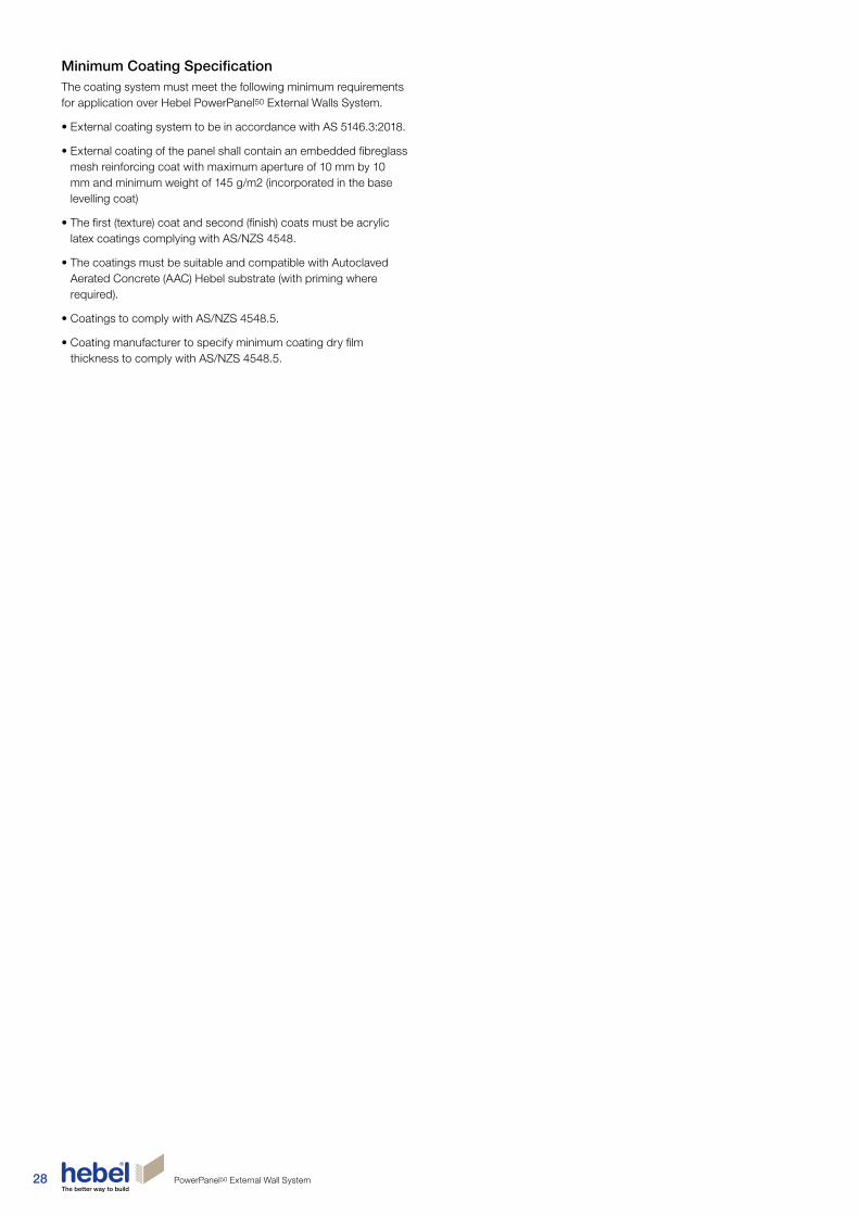
28 PowerPanel50 External Wall System
Minimum Coating SpecificationThe coating system must meet the following minimum requirements for application over Hebel PowerPanel50 External Walls System.
• External coating system to be in accordance with AS 5146.3:2018.
• External coating of the panel shall contain an embedded fibreglass mesh reinforcing coat with maximum aperture of 10 mm by 10 mm and minimum weight of 145 g/m2 (incorporated in the base levelling coat)
• The first (texture) coat and second (finish) coats must be acrylic latex coatings complying with AS/NZS 4548.
• The coatings must be suitable and compatible with Autoclaved Aerated Concrete (AAC) Hebel substrate (with priming where required).
• Coatings to comply with AS/NZS 4548.5.
• Coating manufacturer to specify minimum coating dry film thickness to comply with AS/NZS 4548.5.

29PowerPanel50 External Wall System
GeneralWhen considering weatherproofing, the Hebel PowerPanel50 External Wall System follows the same general design principles considered for the NZBC Acceptable Solution E2/AS1, these being the 4 D’s – Deflection, Drainage, Drying and Durability.
These design principles are discussed further in this section with Durability being covered in section 2.1.
The Hebel PowerPanel50 External Wall System does not fit within the scope of Acceptable Solution E2/AS1, however where possible, it uses the same clearances and makes reference to details and clauses from the Acceptable Solution.
When used in conjunction with other cladding systems (including roof claddings) the Hebel PowerPanel50 External Wall System may only be used on buildings where the wall face concerned has a building envelope risk matrix score of less than 20 as determined using NZBC E2/AS1 section 3.
The Hebel PowerPanel50 External Wall System is a ‘face-sealed’ cavity cladding system, which uses a vapour permeable, water resistant, plaster coating system as its primary means of protection and a cavity system as a secondary defence mechanism against any water ingress, should it occur.
Any water ingress into the cavity is deflected away from penetrations such as windows and doors by the use of flexible DPC flashings. This water will drain within the cavity, deflected away from the wall framing (which is further protected by a wall underlay), by a bevelled horizontal top hat batten or by a sill or bottom edge DPC flashing. The back face of the Hebel panel, will then absorb the moisture and expel it through the vapour permeable, water resistant, plaster coating system.
The drying function occurs in the same manner where any increased atmospheric moisture content within the cavity is also absorbed by the Hebel and expelled through the plaster coating system.
This ‘face-sealed’ cavity cladding system has demonstrated effectiveness and compliance, with considerable in-service history to draw upon, having been used in New Zealand now for over 14 years.
SealantAll gaps between the PowerPanel50 panels and penetrations such as windows and doors must be caulked with an appropriate external grade paintable sealant. Hebel recommends the use of an MS sealant or fire-rated sealant.
All control joints must be sealed with a suitable external grade acoustic and/or fire rated paintable sealant as appropriate. The sealant should be installed in accordance with the sealant manufacturer’s specifications.
Wall FlashingsDPC flashings nominated as part of this system are to be manufactured to meet the requirements of AS/NZS 2904:1995.
Where the DPC flashing is installed over the wall underlay such that the wall underlay does not overlap the DPC flashing (as might occur with a head flashing or base flashing), the DPC flashing shall be fixed to the wall underlay using a waterproof flexible flashing tape so as to cover the upper edge of the flashing.
Where the Hebel PowerPanel50 meets another cladding, the cavity space shall be closed off using a suitable channel flashing. The channel flashing shall be the same depth dimension as the top hat batten and will fit between the wall framing and will fit between the framing and the back of the PowerPanel50.
Building Wrap/Wall UnderlayThe Hebel PowerPanel50 External Wall System has been designed to incorporate wall underlays as a means of controlling condensation for use as an air barrier. The wall underlay material must comply with NZBC E2/AS1 clause 9.1.7.1.
Where the building is situated in an Extra High wind zone or where the cladding system is used on an external wall frame without an internal lining, a rigid wall underlay shall be used.
2.6 Weatherproofing

30 PowerPanel50 External Wall System
3.1 External wall installation sequence
2. Install DPC• Fix to bottom plate
• Cover rebate completely
• Overlap DPC at corners
• Install Building Wrap (or wall underlay) as specified
• Install DPC to wall penetrations such as small pipes, doors and windows
1. Frames and trusses complete
5. Coating• As per project specification with consideration to
Section 2.5 - Coating Requirements Pages 27-28
3. Fix Top Hats• Refer to tables 1.5 - 1.10 on pages 10-11 for
number of Top Hats required (or Tables 2.1 - 2.6 on Pages 19-20 for Boundary Walls)
• Number of screws as per tables 1.4, P10 (or Tables 2.7 for Boundary Walls on P20)
• Install Top Hats below and above openings
• Ensure Top Hats are discontinuous at Control Joints
4. Install Hebel PowerPanel50 panels• Apply tanking membrane to base of panel
• Corner PowerPanel50 panels installed first
• Number of screws as per tables 1.4, P10 (or Tables 2.7 for Boundary Walls on P20)
• Hebel adhesive to vertical joints
• Site cutting to suit
• Coating of exposed reinforcement
• Check control joint layout
• Minimum panel width 270mm

31PowerPanel50 External Wall System
The installation of services in the building are the same as the methods currently being used throughout the industry.
Services should be installed through the frame to avoid interfering with Top Hat layout, but if they are to be fixed on the outside of the frame, they should only run horizontally parallel to the Top Hats – typically 300mm up from the bottom plate and appropriately insulated.
Penetrations through the PowerPanel50 panel for services should be neatly filled and the joint sealed with an external grade acoustic and/or fire rated paintable sealant.
3.3 Installation of services
3.2 Tools and equipment for construction
1
4
3
2
5
Fig. 3.2 – Installed piping services prior to the installation of Hebel PowerPanel50
Fig. 3.3 – Neat finishes of installed services
The basic tools required to assist in the installation of the PowerPanel50 External Wall System are shown in Figure 3.1. These may be purchased through a Hebel distributor and include:
1. Stirrer – fitted to the electric drill, the stirrer is used to mix the Hebel Mortar, Hebel Adhesive and base levelling coat render inside the mixing bucket.
2. Notched Trowel – the notched trowel is used to apply the Hebel Adhesive to the Hebel surfaces. The width of the trowel must match the panel thickness to ensure the adhesive is applied with full and even coverage.
3. Panel lifters – used to carry the panels around the work site.
4. Sand Float – used to remove excess Hebel Adhesive and smooth joints between panels.
5. Levelling Plane – used to even out inconsistencies in the Hebel panels
Extra equipment will also be required and includes the following:
• Power drill (clutch driven).
• Power saw with metal or diamond tipped cutting blades.
• Dust extraction system.
• Sockets for screws.
• Personal Protective Equipment (PPE) such as goggles, ear muffs/plugs and face mask, used when site cutting the PowerPanel50 panels.
Fig. 3.1 – Hebel tools
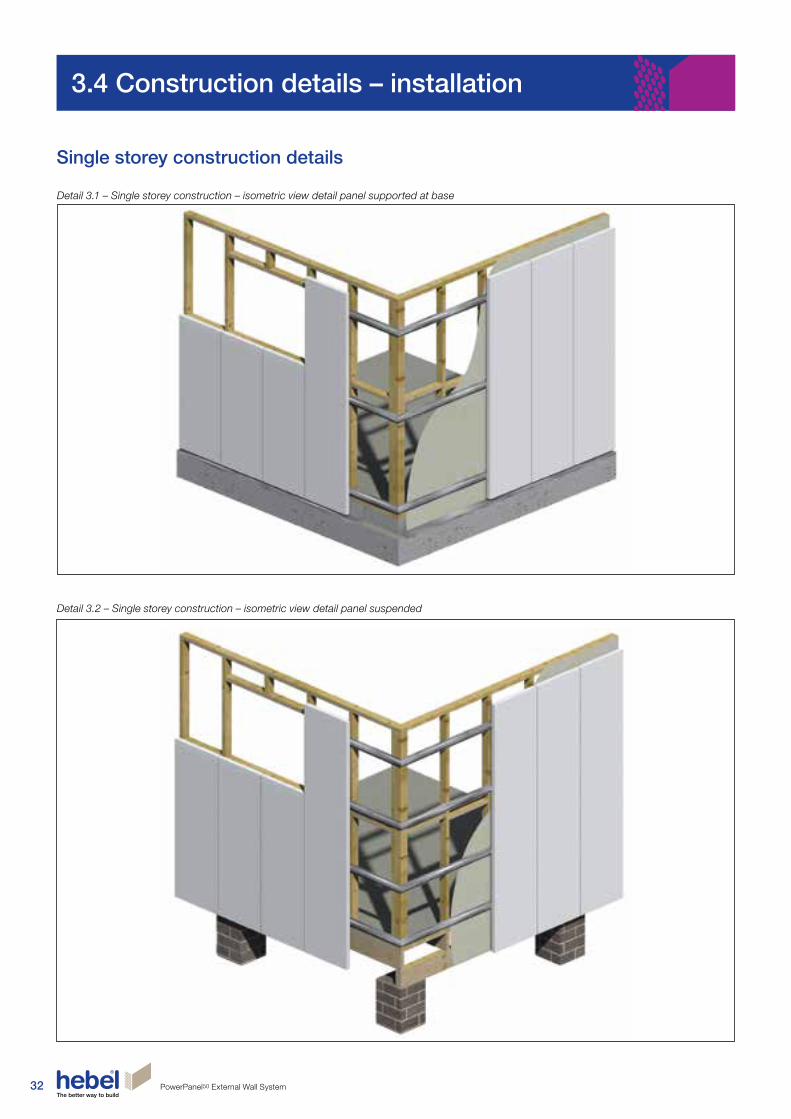
32 PowerPanel50 External Wall System
3.4 Construction details – installation
Detail 3.1 – Single storey construction – isometric view detail panel supported at base
Detail 3.2 – Single storey construction – isometric view detail panel suspended
Single storey construction details

33PowerPanel50 External Wall System
Detail 3.4 – Single storey construction – gable end elevation
NOTE1. Number of Top Hats and Top Hat spacing to be confirmed by the building designer.2. Additional Top Hats may be required, for suspended panels. Refer to tables 1.7 - 1.10 on page 11 for number of Top Hats required (or Tables 2.3 - 2.6 on Page 20 for Boundary Walls)3. These details have not shown the set-out of Top Hats to accommodate control joint locations. This is the responsibility of the building designer.
Detail 3.3 – Single storey construction – hip roof elevation
CONTROL JOINT
TOP OF PANEL
PERFORATED STEEL TOP HAT SECTION
SLAB LEVEL
CONTROL JOINT
NOTE 2
TOP OF PANEL
PERFORATED STEEL TOP HAT SECTION
SLAB LEVEL
FGL
FGL

34 PowerPanel50 External Wall System
Detail 3.6 – Single storey construction – high wall section detail – (3900mm MAX)
Detail 3.5 – Single storey construction – typical section detail
REFER TO DETAIL 3.25
TOP OF WINDOW OR EXTERNAL DOORS
TIMBER STUD OR STEEL STUD FRAME
PERFORATED STEEL TOP HAT SECTION
PENETRATIONS THROUGH HEBEL POWERPANEL50 PANEL FOR SERVICES SHOULD BE NEATLY DRILLED AND THE JOINT SEALED WITH AN PAINTABLE EXTERNAL GRADE SEALANT (ACOUSTIC & FIRE RATED. AS REQUIRED)
HEBEL 50mm POWERPANEL50 PANEL
BUILDING WRAP (OR WALL UNDERLAY)
REINFORCED CONCRETE SLAB
50mm MIN.
50mm MIN.50mm MIN.
DISTANCE TO SATISFY RELEVANT AUTHORITY REQUIREMENTS
REFER TO DETAIL 3.25
TOP OF WINDOW OR EXTERNAL DOORS
TIMBER STUD OR STEEL STUD FRAME
PERFORATED STEEL TOP HAT SECTION
HEBEL 50mm POWERPANEL50 PANEL
BUILDING WRAP (OR WALL UNDERLAY)
24mm GAP TO PANEL TYPICAL
PENETRATIONS THROUGH HEBEL POWERPANEL50 PANEL FOR SERVICES SHOULD BE NEATLY DRILLED AND THE JOINT SEALED WITH AN PAINTABLE EXTERNAL GRADE SEALANT (ACOUSTIC & FIRE RATED. AS REQUIRED)
REINFORCED FIBREGLASS MESH EMBEDDED IN BASE LEVELLING COAT (PARTICULARLY OVER PANEL JOINTS)
HEBEL ADHESIVE IN JOINT
DISTANCE TO SATISFY RELEVANT AUTHORITY REQUIREMENTS
REINFORCED CONCRETE FOOTING
REFER TO FOOTING JUNCTION DETAILS
DPC FLASHINGREINFORCED CONCRETE SLAB
60 MIN. (MAX. PANEL OVERHANG IS 15mm)
DPC FLASHING
FGL
REFER FOOTING JUNCTION DETAILS
REINFORCED CONCRETE FOOTING60 MIN.
(MAX. PANEL OVERHANG IS 15mm)
MA
XIM
UM
SPA
CIN
G\X
AS
PER
PR
OJE
CT
SPE
CIF
ICAT
ION
3900
mm
MA
X.
See
Not
e A
See
Not
e A
150
150
150
150
600 *
50mm MIN.
50mm MIN.FGL
50mm MIN.
NOTE A: Panel length to be selected from available panel lengths as set in section 1.4 - 'System components' of this guide.
* Denotes horizontally aligned 50mm PowerPanel50 panel

35PowerPanel50 External Wall System
Two storey construction
Detail 3.7 – Two storey construction – isometric view detail

36 PowerPanel50 External Wall System
Detail 3.9 – Two storey construction – gable end elevation
Detail 3.8 – Two storey construction – hip roof elevation
NOTE1. Number of Top Hats and Top Hat spacing to be confirmed by the building designer.2. Additional Top Hats may be required, for suspended panels. Refer to tables 1.7 - 1.10 on page 11 for number of Top Hats required (or Tables 2.3 - 2.6 on Page 20 for Boundary Walls)3. These details have not shown the set-out of Top Hats to accommodate control joint locations. This is the responsibility of the building designer.
CONTROL JOINT
TOP OF PANEL
TOP OF PANEL
NOTE 2
NOTE 2
NOTE 2
HORIZONTAL CONTROL JOINT
HORIZONTAL CONTROL JOINT
PERFORATED STEEL TOP HAT SECTION BEYOND
PERFORATED STEEL TOP HAT SECTION BEYOND
SLAB LEVEL
SLAB LEVEL
FGL
FGL

37PowerPanel50 External Wall System
NOTE: These gap widths can be reduced for low shrinkage floor systems. Contact the floor system manufacturer for guidance on acceptable gap width. Refer also to NZS 3604: 2011
Detail 3.10 –Two storey construction – typical timber frame section using joists with >1% shrinkage
Detail 3.11 – Two storey construction – steel frame section or engineered joists with ≤1% shrinkage
REFER TO DETAIL 3.25
TOP OF WINDOW
REFER TO DETAIL 3.25
PENETRATIONS THROUGH HEBEL POWERPANEL50 PANEL FOR SERVICES SHOULD BE NEATLY DRILLED AND THE JOINT SEALED WITH AN PAINTABLE EXTERNAL GRADE SEALANT (ACOUSTIC & FIRE RATED. AS REQUIRED)
HEBEL 50mm POWERPANEL50 PANEL
PERFORATED STEEL TOP HAT SECTION
STEEL STUD FRAME
HEBEL POWERFLOOR
ENGINEERED TIMBER OR STEEL JOISTS
BUILDING WRAP (OR WALL UNDERLAY)
REFER TO DETAIL 3.38
DPC FLASHING
REINFORCED CONCRETE FOOTING
REINFORCED CONCRETE SLAB
PERFORATED STEEL TOP HAT SECTION
TIMBER STUD FRAME
BUILDING WRAP (OR WALL UNDERLAY)
REINFORCED CONCRETE SLAB
HEBEL POWERFLOOR
HEBEL 50mm POWERPANEL50 PANEL
TIMBER JOISTS
50 MIN.
250mm MAX
25mm DEFLECTION GAP250mm MAX
50mm MINFGL
DPC FLASHING
REINFORCED CONCRETE FOOTING
TOP OF WINDOW
50 MIN.
250 MAX
250 MAX
50 MIN. FGL

38 PowerPanel50 External Wall System
Two storey addition
Detail 3.12 – Two storey addition – isometric view detail

39PowerPanel50 External Wall System
NOTE1. These gap widths can be reduced for low shrinkage floor systems. Contact the floor system manufacturer for guidance on acceptable gap width. Refer to Tables 1.7 1.10 on Page 11 for
number of Top Hats required (Or Tables 2.3 - 2.6 on Page 20 for Boundary Walls)
Detail 3.14 – Two storey additions – typical section with double brick below
Detail 3.13 – Two storey additions – typical section with brick veneer below
REFER TO DETAIL 3.25
REFER TO DETAIL 3.25
TIMBER STUD FRAME
BUILDING WRAP (OR WALL UNDERLAY)
PERFORATED STEEL TOP HAT SECTION
HEBEL POWERFLOOR
REFER TO DETAIL 3.39
EXISTING DOUBLE BRICKWORK
DPC FLASHING
REINFORCED CONCRETE FOOTING
REINFORCED CONCRETE SLAB
PENETRATIONS THROUGH HEBEL POWERPANEL50 PANEL FOR SERVICES SHOULD BE NEATLY DRILLED AND THE JOINT SEALED WITH AN PAINTABLE EXTERNAL GRADE SEALANT (ACOUSTIC & FIRE RATED. AS REQUIRED)
HEBEL 50mm POWERPANEL50 PANEL
PENETRATIONS THROUGH HEBEL POWERPANEL50 PANEL FOR SERVICES SHOULD BE NEATLY DRILLED AND THE JOINT SEALED WITH AN PAINTABLE EXTERNAL GRADE SEALANT (ACOUSTIC & FIRE RATED. AS REQUIRED)
TIMBER STUD FRAME
HEBEL 50mm POWERPANEL50 PANEL
TIMBER FLOORING
BUILDING WRAP (OR WALL UNDERLAY)
PERFORATED STEEL TOP HAT SECTION
REFER TO DETAIL 3.40
EXISTING TIMBER FRAME
EXISTING BRICK VENEER
DPC FLASHINGREINFORCED
CONCRETE SLAB
REINFORCED CONCRETE FOOTING
TOP OF WINDOW TOP OF WINDOW
50 MIN. 50 MIN.FGL FGL
25mm DEFLECTION GAP 25mm DEFLECTION GAP
250
MA
X.
250
MA
X.

40 PowerPanel50 External Wall System
PowerPanel50 panel setout – elevation viewTITLEFIGURE
SCALE SHEET SIZE DRAWN DATE
SHEET NO. REVISIONCHECK1:20 @ A3A3 DA 19.08.13
15 of 43 DG C
DESIGN GUIDE REFERENCE
3.20
HEB1353 JUNE 2013
A.B.N. 55 008 631 356
CSR BUILDING PRODUCTS LTDLOCKED BAG 1345, NORTH RYDE BC NSW 1670Head Office: Triniti 3, 39 DELHI RD, NORTH RYDE NSW 2113
Ph: 1300 369 448www.hebelaustralia.com.au
CSR Building Products Limited
112 Wisemans Ferry Road Somersby, NSW 2500 Phone: (02) 4340 3380 A.B.N. 55 008 631 356 Fax: (02) 4340 3300
SCREW LAYOUT DRAWING - ELEVATION VIEW - R
HEBEL POWERPANEL FIXING & INSTALLATION DETAILS - R
2 SCREWS
3 SCREWS
4 SCREWS
100 200 200 100
100 100
100 133 133 133 100
100\XTYP.
SCREW LAYOUT DRAWING - ELEVATION VIEWSCALE 1:20
FGL
LEVEL OF FLOORSLAB
PANELS BUTT JOINTED & GLUED WITHHEBEL ADHESIVE
600 WIDE PANELS
LINE OF CORNER PANELBEYOND
250
MAX
.25
0M
AX.
LINES OF 'TOP HAT'SECTION BEHIND PANELS
SCREW LAYOUT
POWERPANEL50 SETOUT - ELEVATION VIEW
Screw layout
Detail 3.17 – Screw layout drawing
Packer Thickness
(mm)
Minimum Screw Length
(mm)
0 35
5 35
10 35
15 40
20 45
25 50
30 55
35 60
Packer Thickness
(mm)
Minimum Screw Length
(mm)
0 16
5 21
10 26
15 31
20 36
25 41
30 46
35 51
Connection to Timber Stud Connection to Steel Stud
Notes For Connection to Timber Stud
• The stud frame designer shall take into account of any local design action effect to
the stud due to the packer;
• The packer shall be sufficiently solid to prevent the screw from bending;
• The screw size shall be 12-10 x (screw length) Hex Head Type 17 screw.
Notes For Connection to Steel Stud
• There shall be at least 3 full threads penetrating beyond the flange of the steel stud;
• The stud frame designer shall take into account of any local design action effect to
the stud due to the packer;
• The packer shall be sufficiently solid to prevent the screw from bending;
• The screw size shall be 10-16 x (screw length) Hex Head Tek Screw.
Hebel PowerPanel50 external wall system fixing & installation detail
NOTE: When positioning the stud frames allow 5-7mm extra cavity width for the sheet bracing between Top Hat and timber stud.
TYPICAL WALL FIXING DETAIL FROM OUTSIDE TYPICAL WALL FIXING DETAIL WITH PACKER FROM OUTSIDE
Detail 3.16 – Hebel PowerPanel50 External Wall Fixing Detail - Typical Fixing Detail from Outside
BUILDING WRAP (OR WALL UNDERLAY)
BUILDING WRAP (OR WALL UNDERLAY) TIMBER FRAME
TIMBER FRAME PLASTERBOARD
PLASTERBOARD
12 -11x35mm HEX HEAD TYPE 17 SCREW
14 -10x65mm HEX HEAD TYPE 17 SCREW
50mm HEBEL POWERPANEL50 PANEL
COATING SYSTEM AS PER PROJECT SPECIFICATION
LINE OF CORNER PANEL BEYOND
LINES OF 'TOP HAT' SECTION BEHIND PANELS
250
MA
X.
250
MA
X.
600 WIDE PANELS
PANELS BUTT JOINTED & GLUED WITH HEBEL ADHESIVE
LEVEL OF FLOOR SLAB
FGL
PLASTIC PACKER
14 -10x65mm HEX HEAD TYPE 17 SCREW
50mm HEBEL POWERPANEL50 PANEL
COATING SYSTEM AS PER PROJECT SPECIFICATION
PLASTIC PACKER
MIN. SCREW LENGTH
PACKER THICKNESS (MAX 35mm)
24 or 35mm

41PowerPanel50 External Wall System
NOTE1. Do not fix Top Hat to floor joists.2. If non-shrink floor joists are used, gap may be reduced or eliminated. Seek further technical advice from the framing manufacturer.3. Refer to CSR Hebel for Hebel PowerFloor™ details.4. When fixing Top Hats to concrete, contact the fixing manufacturer For details.
Footing junction details
Detail 3.18 – Footing junction detail 1 Detail 3.19 – Footing junction detail 2
Detail 3.20 – Footing junction detail 3
Detail 3.21 – Footing junction detail 4
REINFORCED CONCRETE SLAB & FOOTING
HEBEL 50mm POWERPANEL50 PANEL
TIMBER OR STEEL STUD FRAME
BUILDING WRAP (OR WALL UNDERLAY)
V GROOVE AT BRICK/HEBEL JUNCTION APPLIED TANKING MEMBRANE TO BASE OF PANEL RETURN MINIMUM 15mm UP FRONT FACE OF PANEL
FILL
DCP FLASHING
FGLBLOCKWORK TO UNDERSIDE OF SLAB
REINFORCED STRIP FOOTING
HEBEL 50mm POWERPANEL50 PANEL
BUILDING WRAP (OR WALL UNDERLAY)
TIMBER OR STEELSTUD FRAME
REFER TO NOTE 1
HEBEL POWERFLOOR SEE NOTE 3
REFER TO NOTE 2
FEATURED MOULDING BLOCK GLUED & SCREWED TO PANEL
ANT CAP
POLYURETHANE AIR SEAL OPEN CELL FOAM
DPC FLASHING
ENGAGED BLOCK PIERS
BLOCKWORK TO UNDERSIDE OF PANEL
REINFORCED STRIP FOOTING
FGL
25mm DEFLECTION GAP
REINFORCED CONCRETE SLAB
TIMBER OR STEEL STUD FRAME
HEBEL 50mm POWERPANEL50 PANEL
BUILDING WRAP (OR WALL UNDERLAY)
DPC FLASHING
REINFORCED CONCRETE FOOTING
15mm MAX OVERHANG APPLIED TANKING MEMBRANE TO BASE OF PANEL RETURN MINIMUM 15mm UP FRONT FACE OF PANEL
MIN 50mm BELOW BOTTOM OF HEBEL POWERPANEL50 TO SOIL LINE
FGL
250
MA
X.
50 MIN.
50Timber frame
90
*50
mm
MIN
.
STANDARD FOOTING JUNCTION DETAILUnit 3, 38b Birmingham DriveP O Box 29354Christchurch 8540, New Zealand
Phone: 0800 443 235Email: [email protected]: www.hebel.co.nz CSR Hebel is a division of CSR Building Products (NZ) Ltd.
TITLE
SCALE
FIGURE
SHEET SIZE
SHEET NO.
DRAWN
CHECK
DATE
REVISION
1:5 @ A4
21 -
A4 JP
-
16/03/2016
-
BUILDING WRAP OVER TIMBER FRAMING
WALL INSULATIONTIMBER WALL FRAMINGSELECTED INTERIOR LINING
BOTTOM PLATE FIXED TO CONCRETE AS PER NZS 3604
DPC LAYER
50mm HEBEL POWERPANEL50 WITH EXTERNAL COATING SYSTEM AS SPECIFIED
TOPHAT SECTION
14-10x65mm HEX HEAD TYPE 17 SCREW
50mm MINIMUM TO FINISHED GROUND LEVEL OR 35mm MINIMUM TO PERMANENT PAVING (WITH FALL AWAY FROM BUILDING)
DPC OR ALUMINIUM BASE ANGLE FLASHING FIXED TO BOTTOM PLATE

42 PowerPanel50 External Wall System
.50
Timber frame9050
FOUNDATION FOOTING DETAIL-SUSPENDED PANEL BASE DETAIL
Unit 3, 38b Birmingham DriveP O Box 29354Christchurch 8540, New Zealand
Phone: 0800 443 235Email: [email protected]: www.hebel.co.nz CSR Hebel is a division of CSR Building Products (NZ) Ltd.
TITLE
SCALE
FIGURE
SHEET SIZE
SHEET NO.
DRAWN
CHECK
DATE
REVISION
1:5 @ A4
12 -
A4 JP
-
16/03/2016
-
NOTES1. All garden beds and /or finished soil line must remain a minimum of 50mm below the bottom of the finished rendered wall.
Detail 3.23 – Base detail suspended floor – pier connection
NOTE 1. Refer to Table 1.7 and 1.10 for Top Hat requirement for suspended applications2. This detail is not considered to achieve a fire rating level
Detail 3.22 – Footing junction detail 5
Detail 3.24 – Suspended Panel at Slab Edge Detail
COATING SYSTEM AS PER PROJECT SPECIFICATION
EXISTING BLOCK PIER
GALVANISED ANGLE STRUCTURE TO ENGINEERS DETAILS2 x NO. 12- 11x35 TIMBER SCREWS TO STUDSDISCONTINUOUS PERFORATED STEEL TOP HAT SECTIONCONTROL JOINT REQUIRED AT EVERY PIERBACKING ROD
NO. 14 -10 x 65mm HEX HEAD TYPE 17 SCREW
PAINTABLE EXTERNAL GRADE SEALANT (ACOUSTIC AND/OR FIRE RATED, AS REQUIRED)
COATING SYSTEM AS PER PROJECT SPECIFICATION
NO. 14 -10 x 65 HEX HEAD TYPE 17 SCREW
TIMBER FRAMED EXTERNAL WALLS
BUILDING WRAP (OR WALL UNDERLAY)
HEBEL 50mm POWERPANEL50 PANEL
PAINTABLE EXTERNAL GRADE SEALANT (ACOUSTIC AND/OR FIRE RATED, AS REQUIRED)
7.5mm
10mm THICK ABLEFLEX OR BACKING ROD
CONTROL JOINT
EXISTING PIER/STUMPS
NEW LOAD BEARING BEAM OR FRAME SUPPORTED OFF EXISTING PIERS BY STRUCTURAL ENGINEER (FACE TO ALIGN WITH EXISTING FACADE)
GALVANISED ANGLE STRUCTURE TO SUIT ENGINEERS REQUIREMENTS
90x45mm H1.2 TREATED SG8 WALL FRAMING
BUILDING WRAP OVER TIMBER FRAMING
WALL INSULATION
SELECTED INTERIOR LINING
BOTTOM PLATE FIXED TO CONCRETE AS PER NZS 3604
50mm HEBEL POWERPANEL50 WITH EXTERNAL COATING SYSTEM AS SPECIFIED
14-10x65mm HEX HEAD TYPE 17 SCREW
DPC LAYER
BUILDING WRAP DOWN OVER BASE ANGLE
50mm MINIMUM TO FINISHED GROUND LEVEL OR 35mm MINIMUM TO PERMANENT PAVING (WITH FALL AWAY FROM BUILDING)
BASE ANGLE FIXED TO BOTTOM PLATE TIMBER TO TEMPORARILY SUPPORT PANEL AND CLOSE TOP HAT CAVITY*
*NOTE : THIS BASE ANGLE DETAIL IS NOT APPLICABLE FOR A FIRE RATED WALL- SEE SECTION 2.2
TOPHAT SECTION

43PowerPanel50 External Wall System
Wall junction details & sections
Detail 3.25 – Typical roof eaves detail
OPTION 1 OPTION 2 OPTION 1 OPTION 2
RO
OF
AN
D C
EILI
NG
ST
RU
CTU
RE
RO
OF
AN
D C
EILI
NG
ST
RU
CTU
RE
EXTERNAL FRAME
EXTERNAL FRAME
NOMINAL 20mm
BACKING ROD
SOFFIT/EAVES LINING BOARD
SOFFIT/EAVES LINING BOARD
24mm OR 35mm HEBEL PERFORATED TOP HAT
PAINTABLE EXTERNAL GRADE SEALANT (ACOUSTIC AND/OR FIRE RATED. AS REQUIRED)
COATING SYSTEMS AS PER PROJECT SPECIFICATION
COATING SYSTEMS AS PER PROJECT SPECIFICATION
24mm OR 35mm HEBEL PERFORATED TOP HAT
BUILDING WRAP (OR WALL UNDERLAY)
BUILDING WRAP (OR WALL UNDERLAY)
50mm HEBEL POWERPANEL50 PANEL50mm HEBEL POWERPANEL50 PANEL

44 PowerPanel50 External Wall System
EXTERNAL FRAME
NOTE: PARAPET CAPPING DETAIL TO BE CONSTRUCTED IN ACCORDANCE WITH E2/AS1, SECTION 6.
CLEARANCE TO ALLOW FOR TIMBER FRAME SHRINKAGE
FALL
24mm OR 35mm HEBEL PERFORATED TOP HAT
CLIP AND SCREW TO SUIT CAPPING
BUILDING WRAP (OR WALL UNDERLAY)
COATING SYSTEMS AS PER PROJECT SPECIFICATION
STRUCTURAL WALL FRAMING
CONTINUOUS SOLID TIMBER BLOCKING
50mm HEBEL POWERPANEL50 PANEL
TIMBER SUPPORT
CONTINUOUS SOLID TIMBER BLOCKING
GUTTER
FASCIA BOARD
24mm OR 35mm HEBEL PERFORATED TOP HAT
COATING SYSTEMS AS PER PROJECT SPECIFICATION
BUILDING WRAP (OR WALL UNDERLAY)
50mm HEBEL POWERPANEL50 PANEL
RO
OF
AN
D C
EILI
NG
ST
RU
CTU
RE
Detail 3.28 – Roof to wall junction detail Detail 3.29 – Balcony to Wall Junction Detail
Detail 3.26 – Typical roof eaves detail (no eave overhang) Detail 3.27 – Typical roof/parapet wall detail
BUILDING WRAP (OR WALL UNDERLAY) LAPPED OVER BASE ANGLE
HEBEL 50mm POWERPANEL50 PANEL (BASE OF PANEL TO BE CUT PARALLEL TO BALCONY FINISH)
BUILDING WRAP (OR WALL UNDERLAY) LAPPED OVER BASE ANGLE
APPLY TANKING MEMBRANE TO BASE OF PANEL RETURN MINIMUM 15mm UP FRONT FACE OF PANEL
35mm MIN AT HIGHEST POINT OF BALCONY
150m
m
BASE ANGLE FIXED TO TIMBER FRAME
BALCONY MEMBRANE (MORTAR BED AND TILE OVER)
HEBEL 50mm POWERPANEL50 PANEL (BASE OF PANEL TO BE CUT PARALLEL TO ROOF SHEETING)
APPLY TANKING MEMBRANE TO BASE OF PANEL RETURN MINIMUM 15mm UP FRONT FACE OF PANEL
BASE ANGLE FIXED TO TIMBER FRAME
35mm
75mm MIN
FLASHING TO PROJECT SPECIFICATION (TO BE PLACED OVER ROOF SHEETING AS PER E2/AS1 AND PROJECT BEYOND BASE OF PANEL BY 75mm)

45PowerPanel50 External Wall System
Detail 3.31 – Gable end wall detail Detail 3.32 – Gable end wall detail – lintel panel over window
Detail 3.30 – Beam penetration detail
Detail 3.33 – Column Detail (Glued & Screwed)
HEBEL POWERPANEL50 PANEL
EXTRA STUDWORK
SCREWS FIXED AT 600mm CENTRES USING No.14 -10 x 150mm HEX HEAD TYPE 17 SCREWS
750mm MAX
600mm MAX
50mm 50mm
50mm HEBEL POWERPANEL50 PANEL
100mm x 100mm TIMBER SUPPORT POST
TOP HAT
14-10x65mm HEX HEAD SCREWS
MESH EMBEDDED IN TEXTURE COAT (ALL AROUND COLUMN)
GLUE TO ALL JOINTS
EXTRA STUDWORK
TRUSS TRUSS
PAINTABLE EXTERNAL GRADE SEALANT (ACOUSTIC AND/OR FIRE RATED. AS REQUIRED)
PAINTABLE EXTERNAL GRADE SEALANT (ACOUSTIC AND/OR FIRE RATED. AS REQUIRED) BUILDING
WRAP (OR WALL UNDERLAY)
FLEXABLE FLASHING TAPE
DPC HEAD FLASHING
TIMBER LINTEL OVER WINDOW DESIGNED TO SUPPORT HEBEL 50mm POWERPANEL50 PANEL LOADING OVER
HEBEL 50mm POWERPANEL50 PANEL TO BE EXTERNALLY FACED FIXED TO TOP HATS WITH No.14 -10x65mm HEX HEAD TYPE 17 SCREWS @600cts
50 SLOPESEALANTWINDOW FRAME
250m
m M
AX
250m
m M
AX
10mm ABLEFLEX
10mm ABLEFLEX
SOLID PACKER
SOLID PACKER
HEBEL 50mm POWERPANEL50 PANEL
BUILDING WRAP (OR WALL UNDERLAY)
BEAM PENETRATION THROUGH WALL
10mm GAP TO ALLOW FOR MOVEMENT, FILLED WITH EXTERNAL GRADE PAINTABLE SEALANT
10mm
2mm GAP

46 PowerPanel50 External Wall System
Control jointsControl Joints are a necessary part of a rendered wall system to ensure that the location of possible cracking is controlled, movement isolated and stresses relieved from the wall elements. Such stresses can occur as a result of:
• Differential movement in materials due to temperature and humidity changes i.e between wall framing and rendered substrate
• Long term settlement of foundations or general ground movement due to soil expansion and contraction
• Seismic movement – for compliance with NZBC the cladding system is required to cope with SLS (service limit state) loads without compromising the integrity of the system.
Control joints may serve as a location for the joint to open or close only, or both. The designer must consider the type and magnitude of movement when detailing the control joints.
Important: A common mistake with rendering and Control Joint installation is the application of render, mesh or texture over the joint. Such application will be detrimental to the ability of the Control Joint to operate as intended as it will restrict movement and reveals itself with cracking and spalling of the joint. Secondary damage can then result from water ingress through the crack, working its way behind the coating system. Importantly, all joints should be filled with an appropriate flexible sealant that can accommodate the movements and durability for the application. The render, mesh and texture coating should be terminated at the sealant/panel interface and not impede the differential movement between the panel and adjacent structure or another panel.
The following information provides the necessary rules for Control Jointing when installing the Hebel PowerPanel50 External Wall System
• Vertical Control Joints required at maximum 6m centres
• Vertical Control Joints required at external and internal corners or up to a maximum distance of 1200mm away from the corner along one wall face
Refer to detail 3.37 & 3.38 for control joint guidelines where installed away from external & internal corner
• Vertical control joints may be required above and below doors (including sliding and garage doors) and openings to floor level depending on opening width, however, where the depth of the panel is less than 270mm control joints are recommended to both sides of the opening – see opening width rules below
• Horizontal Control Joints Required at every horizontal floor junction
• Horizontal Control Joints required at a maximum height of 3.9m
Control Joints in Gable End WallsHorizontal control joints in gable end walls shall normally be constructed as per Detail 3.31 or 3.32, however, they may be excluded from these walls in situations where:
a) The total height of the wall cladding as measured to the ridge does not exceed 6m; and
b) The section of the external gable wall located above the ceiling plane (to which the top hat battens will be fixed) is constructed and fixed directly to the wall below as required for a load bearing wall in accordance with NZS 3604:2011; and
c) The foundation support for the gable end wall is founded on ‘good ground’ as defined by NZS 3604:2011 or has been designed so as to limit settlement (or heave) of the foundation that may otherwise induce in-plane stresses in the Hebel cladding.
Note: also that the top hat batten spacing on wall framing above the ceiling plane (with or without the use of control joints) shall be as required for suspended panel installation.
For openings < 2450mm in width• Control Joint not required.
Note: The minimum panel height above or below openings is 270mm, however this may be reduced to a minimum of 150mm where the panel is directly fixed to a top hat batten behind. Where the depth of the panel is less than 270mm control joints shall are recommended to both sides of the opening. Furthermore, caution must be exercised to avoid cracking during cutting, handling and installation of such panels
For openings >= 2450mm and < 3600mm wide • Control Joint required to at least one side of the opening (i.e.
above and below the opening).
Note: The minimum panel height above or below openings is 270mm, however this may be reduced to a minimum of 150mm where the panel is directly fixed to a top hat batten behind. Where the depth of the panel is less than 270mm control joints shall are recommended to both sides of the opening. Furthermore, caution must be exercised to avoid cracking during cutting, handling and installation of such panels
For openings >= 3600mm in width
• Control Joint required to both sides of the opening (i.e. above and below the opening).
Note: The minimum panel height above or below openings is 270mm, however this may be reduced to a minimum of 150mm where the panel is directly fixed to a top hat batten behind. Where the depth of the panel is less than 270mm control joints shall are recommended to both sides of the opening. Furthermore, caution must be exercised to avoid cracking during cutting, handling and installation of such panels
Detail 3.34 – Internal corner
Detail 3.35 – External corner
PAINTABLE EXTERNAL GRADE SEALANT (ACOUSTIC AND/OR FIRE RATED, AS REQUIRED)
HEBEL POWERPANEL50
PANEL
EXTERNAL FRAME
PERFORATED STEEL TOP HAT SECTION
HEBEL POWERPANEL50 PANEL
PAINTABLE EXTERNAL GRADE SEALANT (ACOUSTIC AND/OR FIRE RATED, AS REQUIRED)
5 - 10mm
No. 14 -10x65mm HEX HEAD TYPE 17 SCREW
COATING SYSTEMS AS PER PROJECT SPECIFICATION
EXTERNAL FRAME
HEBEL POWERPANEL50 PANEL
PERFORATED STEEL TOP HAT SECTION
COATING SYSTEMS AS PER PROJECT SPECIFICATION
EXTERNAL FRAME

47PowerPanel50 External Wall System
50mm HEBEL POWERPANEL50 PANEL
INSTALL CONTROL JOINT WITHIN 6M OF EXTERNAL CORNER
INSTALL CONTROL JOINT WITHIN 6M OF EXTERNAL CORNER
INSTALL CONTROL JOINT AT MAX. 1200mm (UP TO 2 FULL PANEL WIDTHS) FROM EXTERNAL CORNER TO AT LEAST ONE RETURN WALL FACE
INSTALL CONTROL JOINT AT MAX. 1200mm (UP TO 2 FULL PANEL WIDTHS) FROM INTERNAL CORNER TO AT LEAST ONE RETURN WALL FACE
50mm HEBEL POWERPANEL50 PANEL
6-10mm CONTROL JOINT
6-10mm CONTROL JOINT
Detail 3.37 – Typical detail for control joints positioned away from a wall external corner
Detail 3.38 – Typical detail for control joints positioned away from a wall internal corner
NOTE: Mesh to be installed upon application of the External Coating System to the panels. Mesh must be installed within the Base Levelling Coat
NOTE: Mesh to be installed upon application of the External Coating System to the panels. Mesh must be installed within the Base Levelling Coat

48 PowerPanel50 External Wall System
Detail 3.41 – Typical vertical control joint
Control Joint Details
Detail 3.38 – Typical horizontal control joint steel stud frame or engineered timber joists ≤1% shrinkage
Detail 3.37 – Typical horizontal control joint – timber stud frame using joists with >1% shrinkage
Detail 3.39 – Horizontal control joint – cavity brickwork to Hebel PowerPanel50 Panel
Detail 3.40 – Horizontal control joint – brick veneer to Hebel PowerPanel50 Panel
Detail 3.42 – Typical vertical control joint (discontinuous Top Hat on a double stud)
NOTE: The position of the horizontal control joint must be such that the panel must not cantilever more than 250mm past the last Top Hat, top and bottom. Top Hats must not be fixed to joists
50mm HEBEL POWERPANEL50 PANEL
HEBEL 50mm POWERPANEL50 PANEL
COATING SYSTEMS AS PER PROJECT SPECIFICATIONS
250m
m M
AX
250m
m M
AX
250m
m
MA
X 75
250m
m
MA
XHEBEL 50mm POWERPANEL50 PANEL
ENGINEERED TIMBER OR STEEL JOIST
7.5mm SOLID PACKER
PAINTABLE EXTERNAL GRADE SEALANT (ACOUSTIC AND/OR FIRE RATED. AS REQUIRED)
50mm ABLEFLEX
COATING SYSTEMS AS PER PROJECT SPECIFICATIONS
TEMPORARY TIMBER PACKER DURING CONSTRUCTION ONLY REMOVE ON COMPLETION
POLYURETHANE AIR SEAL OPEN CELL FOAM
FEATURE MOULDING FIXED TO TOP PANEL
25mm DEFLECTION GAP
RECESSED TO ALLOW FOR MOVEMENT
HEBEL 50mm POWERPANEL50 PANEL
BUILDING WRAP (OR WALL UNDERLAY)
50 x 50 POLYURETHANE AIR SEAL OPEN CELL FOAM
DISCONTINUOUS TOP HAT SECTION
DISCONTINUOUS TOP HAT SECTION
BACKING RODBACKING ROD
COATING SYSTEMS AS PER PROJECT SPECIFICATION COATING SYSTEMS AS PER
PROJECT SPECIFICATION
5 -10mm5 -10mm
PAINTABLE EXTERNAL GRADE SEALANT (ACOUSTIC AND/OR FIRE RATED. AS REQUIRED) PAINTABLE EXTERNAL GRADE SEALANT
(ACOUSTIC AND/OR FIRE RATED. AS REQUIRED)
HEBEL 50mm POWERPANEL50 PANEL
FEATURE MOULDING GLUED TO TOP PANEL WITH SUITABLE ADHESIVE & MECHANICAL FIXINGS
FEATURE MOULDING GLUED TO TOP PANEL WITH SUITABLE ADHESIVE & MECHANICAL FIXINGS
25mm DEFLECTION GAP
RECESSED TO ALLOW FOR MOVEMENT
POLYURETHANE AIR SEAL OPEN CELL FOAM
TEMPORARY TIMBER PACKER DURING CONSTRUCTION ONLY REMOVE ON COMPLETION
25mm DEFLECTION GAP
50
50
RECESSED TO ALLOW FOR MOVEMENT
TEMPORARY TIMBER PACKER DURING CONSTRUCTION ONLY REMOVE ON COMPLETION

49PowerPanel50 External Wall System
Detail 3.43 Control joint – discontinuous Top Hats on a single stud
Detail 3.44 – Typical window control joint detail – lintel over
NOTE: The installation sequence of the PowerPanel50 panels around the openings should be followed as numbered if there is no control joint at the opening, to maintain glue thickness on the edge of the panel.
SINGLE STUD
TOP HAT SCREWS
PERFORATED STEEL TOP HAT SECTION
HEBEL 50mm POWERPANEL50 PANEL
PANEL SCREW
PERFORATED STEEL TOP HAT SECTION
10mm CONTROL JOINT AT WINDOW FILL WITH PAINTABLE EXTERNAL GRADE SEALANT (ACOUSTIC AND FIRE RATED, AS REQUIRED)
WINDOW TO SUIT 300 MODULE
WIN
DOW O
PENIN
G
RETURN PAINTABLE EXTERNAL GRADE SEALANT (ACOUSTIC AND FIRE RATED, AS REQUIRED) TO INSIDE SURFACE OF HEBEL 50mm POWERPANEL50 PANEL (BEYOND WINDOW FRAME)
10mm CONTROL JOINT AT WINDOW FILL WITH PAINTABLE EXTERNAL GRADE SEALANT (ACOUSTIC AND/OR FIRE RATED, AS REQUIRED)
1
2
2 3
4
300mm WIDE PANEL TO SUIT MODULAR WINDOW
NOTE: TOP HAT LAPS ON STUD
NOTE: PERFORATED STEEL TOP HAT BATTEN DISCONTINUOUS BEHIND CONTROL JOINT
CUT HEBEL 50mm POWERPANEL50 PANEL TO ALLOW FOR 10mm JOINT
6 -10mm CONTROL JOINT

50 PowerPanel50 External Wall System
Door & window detail
Detail 3.47 – Typical window sill detail – aluminium window frame - OPTION 2
Detail 3.46 – Typical window sill detail – aluminium window frame - OPTION 1
Detail 3.45 – Window flashing detail
Detail 3.48 – Typical window sill detail – aluminium window frame - OPTION 3
Detail 3.48a – typical window sill detail - timber window sill joinery detail
FLEXIBLE FLASHING TAPE TO FINISH OVER ENTIRE LENGTH OF THE TOP OF THE HEAD FLASHING
BUILDING PAPER/WALL WRAP TAPED TO WINDOW HEAD WITH FLASHING TAPE AS PER E2/AS1
DPC HEAD FLASHING TO CONTINUE PAST SIDE FLASHINGS TO ENSURE DISCHARGE FROM HEAD TO SILL
FLEXIBLE FLASHING TAPE, AS PER E2/AS1, TO ATTACH THE BUILDING PAPER/WRAP AROUND OPENING
HEAD AND SIDE FLASHINGS MADE FROM 150mm DPC
SIDE U SHAPED DPC FLASHING TO CONTINUE PAST TOP OF SILL FLASHING
SILL FLASHING TO PROJECT 150mm PAST OPENING
DPC SILL FLASHING, BENT UP 100mm INSIDE FRAMED OPENING
SILL TRAY FLASHING FROM 300mm DPC STAPLED TO FRAME
SILL TRAY FLASHING INSTALLED BY OWNER, ON TOP OF THE SILL FRAMING AND BENT DOWN WITH 200mm DRAPED INTO THE CAVITY SPACE
ALUMINIUM SLIDING WINDOW ALUMINIUM SLIDING WINDOW
TIMBER REVEAL TIMBER REVEAL
ALLOW A 10mm GAP FOR FRAME SHRINKAGE OR AS REQUIRED BY PROJECT ENGINEER
ALLOW A 10mm GAP FOR FRAME SHRINKAGE OR AS REQUIRED BY PROJECT ENGINEER
COATING SYSTEMS AS PER PROJECT SPECIFICATION
COATING SYSTEMS AS PER PROJECT SPECIFICATION
BITUMAN DAMP PROOF COATING APPLIED TO SILL (MULSEAL PLUS OR SIMILAR)
TIMBER WINDOW JOINERY
TIMBER WINDOW FRAME
THE FRONT EDGE OF THE WINDOW JOINERY TO BE 40mm MINIMUM FROM THE STUD FACE
MINIMUM 15° SLOPE SILL
TIMBER WINDOW SILL
COATING SYSTEM AS PER PROJECT SPECIFICATIONS
HEX HEAD SCREW
TIMBER ARCHITRAVE (OPTIONAL)
SEALANT
PACKER AND AIR SEAL
SILL TRAY FLASHING ON TOP OF SILL FRAMING AND BENT DOWN 200mm INTO CAVITY SPACE (OVER FIRST TOPHAT SECTION)
OPTIONAL SILL BLOCK GLUED TO PANEL
STEEL BATTEN
12 - 11 x 35mm HEX HEAD BATTEN SCREW
HEBEL 50mm POWERPANEL50 PANEL
TIMBER FRAME
BUILDING WRAP (OR WALL UNDERLAY)
INTERIOR LINING
BUILDING WRAP (OR WALL UNDERLAY) BUILDING WRAP (OR WALL UNDERLAY)
HEBEL ADHESIVE TO JOINT
TIMBER STUD TIMBER STUD
HEBEL 50mm POWERPANEL50 PANEL
ALLOW A 10mm GAP FOR FRAME SHRINKAGE OR AS REQUIRED BY PROJECT ENGINEER
BITUMEN DAMP PROOF COATING APPLIED TO SILL (MULSEAL PLUS OR SIMILAR)
SILL TRAY FLASHING ON TOP OF SILL FRAMING AND BENT DOWN 200mm INTO CAVITY SPACE (OVER FIRST TOP HAT SECTION)
COATING SYSTEMS AS PER PROJECT SPECIFICATION
BUILDING WRAP (OR WALL UNDERLAY)
HEBEL 50mm POWERPANEL50 PANEL
TIMBER STUD
15° MINIMUM SLOPE TO SILL
HEBEL 50mm POWERPANEL50 PANEL
15° MINIMUM SLOPE TO SILL15° MINIMUM SLOPE TO SILL
BITUMEN DAMP PROOF COATING APPLIED TO SILL (MULSEAL PLUS OR SIMILAR) SILL TRAY FLASHING ON TOP OF SILL FRAMING AND BENT DOWN 200MM INTO CAVITY SPACE (OVER FIRST TOP HAT SECTION)
BITUMEN DAMP PROOF COATING APPLIED TO SILL (MULSEAL PLUS OR SIMILAR)
SILL BLOCK
Note: 1. Window frame not shown. Dpc sill flashing is installed,
Before window is installed. Side & head flashing installed After window is installed.
2. Typical head and jamb details apply at all doors Including garage doors.
3. Detail applies at meter boxes and square edge Penetrations of dimension larger than 100mm.
SILL TRAY FLASHING ON TOP OF SILL FRAMING AND BENT DOWN 200MM INTO CAVITY SPACE (OVER FIRST TOP HAT SECTION)

51PowerPanel50 External Wall System
Detail 3.49 – Window header - alternative detail
Detail 3.49 – Window header detail
Detail 3.51 – Typical door jamb detail Detail 3.51 – Garage door jamb detail
Detail 3.50 – Garage head detail
Detail 3.49a – Timber window head - joinery detail
COATING SYSTEM AS PER PROJECT SPECIFICATIONS
COATING SYSTEM AS PER PROJECT SPECIFICATIONS
DOOR GARAGE DOOR
SEALANT
PLASTERBOARD
FRAME
BUILDING WRAP (OR WALL UNDERLAY)
HEBEL 50mm POWERPANEL50 PANEL
COATING SYSTEMS AS PER PROJECT SPECIFICATION
EXTERNAL CORNER RENDER BEAD
FRAME
BUILDING WRAP (OR WALL UNDERLAY)
JAMB
HEBEL 50mm POWERPANEL50 PANEL
TIMBER STORM MOULD OR QUAD OR MS SEALANT
COATING SYSTEM AS PER PROJECT SPECIFICATIONS
24mm or 35mm 24mm or 35mm
BUILDING WRAP (OR WALL UNDERLAY)
BUILDING WRAP (OR WALL UNDERLAY)
TOP HATS
PLASTERBOARD
HEBEL 50mm POWERPANEL50 PANEL
COATING SYSTEMS AS PER PROJECT SPECIFICATION
LINTEL OVER GARAGE
BUILDING WRAP (OR WALL UNDERLAY)
CONSTRUCTION ADHESIVE, ie. MAX BOND OR SIMILAR
NAIL FIBRE CEMENT TO TIMBER AND ABUT TO HEBEL POWERPANEL50 PANEL
FLEXIBLE FLASHING TAPE
SEALANT
FIBRE CEMENT
HEAD FLASHING MADE FROM 150mm DCP
EXTERNAL CORNER RENDER BEAD
5° SLOPE
BUILDING WRAP (OR WALL UNDERLAY)
TIMBER FRAMEINTERIOR LINING
INTERIOR LINING
INTERIOR LINING
STEEL BATTEN
12 - 11 x 35mm HEX HEAD BATTEN SCREW
HEAD SCREW
FLEXIBLE FLASHING TAPE ATTACHED TO THE DPC HEAD FLASHING AND BUILDING WRAP (OR WALL UNDERLAY)
SEALANT
DPC HEAD FLASHING
PACKER AND AIR SEAL
REBATED HEAD BACK FLASHING
TIMBER WINDOW JOINERY
TIMBER WINDOW FRAME
5° SLOPE
FLASHING AT 15° SLOPE
HEBEL 50mm POWERPANEL50 PANEL
HEBEL 50mm POWERPANEL50 PANEL
HEBEL 50mm POWERPANEL50 PANEL
STEEL BATTEN
STEEL BATTEN
5° SLOPE
HEAD SCREW
HEAD SCREW
FLEXIBLE FLASHING TAPE ATTACHED TO THE DPC HEAD FLASHING AND BUILDING WRAP (OR WALL UNDERLAY)
FLEXIBLE FLASHING TAPE ATTACHED TO THE DPC HEAD FLASHING AND BUILDING WRAP (OR WALL UNDERLAY)
GAP BETWEEN JOINERY AND PANEL FILLED WITH SEALANT AND COVERED BY ACRYLIC COATING
GAP BETWEEN JOINERY AND PANEL FILLED WITH SEALANT AND COVERED BY ACRYLIC COATING
TIMBER FRAME
TIMBER FRAME
HEAD FLASHING MADE FROM 150mm DPC
PACKER AND AIR SEAL
PACKER AND AIR SEAL
TIMBER JAMB LINER
TIMBER JAMB LINER
WINDOW OPENING
WINDOW OPENING
ALUMINIUM DOOR HEADER FRAMING 40mm FROM FLANDGE TO FRAME
5° SLOPE
FLASHING AT 15° SLOPE
40mm MIN
NOTE: Drainage of window and door sills, in either aluminium or timber, should be directed to the outside of the building, on top of the window sill.
COATING SYSTEMS AS PER PROJECT SPECIFICATION
SCREW AND GLUE TO HEBEL POWERPANEL50 PANEL USING LIQUID NAILS OR EQUIVALENT
24mm or 35mm

52 PowerPanel50 External Wall System
Detail 3.53 – Sliding door sill detail – option 2 - concrete sill >270mm
Detail 3.52 – Sliding door sill detail – option 1 – concrete sill < 270mm
10mm CONTROL JOINT AT SLIDING DOOR FILL WITH PAINTABLE EXTERNAL GRADE SEALANT (ACOUSTIC AND FIRE RATED, AS REQUIRED)
RETURN PAINTABLE EXTERNAL GRADE SEALANT (ACOUSTIC AND FIRE RATED, AS REQUIRED) TO INSIDE SURFACE OF HEBEL 50mm POWERPANEL50 PANEL (BEYOND DOOR FRAME)
HEBEL 50mm POWERPANEL50 PANEL
MINIMUM 100mm
FLOATING TOP HAT FIXED TO SIDE PANELS USING 14 - 10 x 90mm HEX HEAD SCREWS
5 -10mm DUMMY JOINT
5 -10mm DUMMY JOINT
PACK TOP HAT (IF REQUIRED) TO PREVENT TOP HAT DEFLECTION INWARDS
SLAB LEVEL
LESS THAN 270mm
270mm MINIMUM
WHERE CONCRETE SILL IS LESS THAN 270mm IN HEIGHT, SILL MUST BE FORMED BY CONCRETE TO FINISH FLUSH WITH HEBEL PANELS EITHER SIDE OF DOOR
CONCRETE SILL
5-10mm C.J

53PowerPanel50 External Wall System
Miscellaneous details
NOTE1. At corners, PowerPanel50 panels can be laid out at 300mm multiples in one direction and 300mm multiples + 60mm in the other direction 2. Width of PowerPanel50 panels may vary + or - 1.5mm
Detail 3.54 – Panel layout drawing – plan view
TITLEFIG
URE
SCALE
SHEET SIZE
DRA
WN
DA
TE
SHEET N
O.REV IS IO
NCH
ECK1:50 @
A3
A3
DA
07.08.13
of 43D
GC
DESIG
N G
UID
E REFERENCE
39
HE
B1353 JUN
E 2013
A.B
.N. 55 008 631 356
CS
R B
UILD
ING
PR
OD
UC
TS LTD
LOC
KE
D B
AG
1345, NO
RTH
RY
DE
BC
NS
W 1670
Head O
ffice: Triniti 3, 39 DE
LHI R
D, N
OR
TH R
YD
E N
SW
2113
Ph: 1300 369 448
ww
w.hebelaustralia.com
.auCSR
Building Products
Limited
112 W
isemans Ferry R
oad
Somersby, N
SW
2500 P
hone: (02) 4340 3380 A
.B.N
. 55 008 631 356 Fax: (02) 4340 330 0
PA
NE
L LAY
OU
T DR
AW
ING
- PLA
N V
IEW
- R
MIS
CE
LLAN
EO
US
DE
TAILS
- R
16,9505,650
1,75060
4,67010
4,80060
60 1,050 1,800 1015 60 1,350 275 2,895 3003,935 1,350 3,445
17,6504,000
13,6501,200
2,100725
3502,400
1,5002,100
1,500600
10430
1,2003,575
8,730275 1,825 60 1,460 2,400 1,200 900 600 60
1,125425
700
550 1,500 910 502,985
1,210 1,500 300
820
820
TYPEA
B
C
D
E
F
G
H
J
SIZE QTY600 WIDE FULL HEIGHT
300 WIDE FULL HEIGHT
600 WIDE WINDOW HEIGHT
300 WIDE WINDOW HEIGHT
VERTICAL SITE CUT FROM A
HORZ. SITE CUT FROM C
HORZ. SITE CUT FROM D
HORZ. SITE CUT FROM A
HORZ. SITE CUT FROM B
47
12
-
-
7
8
2
5
1
AA
AA
AA
AA
AB
BA
CJ
A HJ H
A BBE G FF
AA
AA
AA
AA
AA
AA
AA
AE
CJ
BB
AA E
CJ
CJ
FF FA A EE
CJA
AA
AA
A
CJ
HH
E
CJ
HA
AB
GF
FF
AA
BB
B
AA
BE
AAAABE
CJ
CJ
PA
NE
L LAY
OU
T DR
AW
ING
- PLA
N V
IEW
1:50
39
3.56

54 PowerPanel50 External Wall System
Unloading panel packsPanel packs should only be unloaded and moved with approved lifting devices. Before use, the lifting devices should be checked for the required lifting tags. Packs should be unloaded as close as possible to the intended installation area. This will increase work efficiency and minimise the need for secondary lifting.
NOTE: Secondary handling increases the risk of panel damage. The repair of damage sustained during lifting and moving is the responsibility of the lifter. Where damage is excessive, PowerPanel50 panels must be replaced.
StorageAll materials must be kept dry and preferably stored undercover. Care should be taken to avoid sagging or damage to ends, edges and surfaces.
All Hebel products must be stacked on edge and properly supported off the ground, on a level platform. Panel bundles can be stacked two high. The project engineer should be consulted as to the adequacy of the structure to support the stacked bundles.
If outside, Hebel panels must be stored off the ground and protected from the weather. Only single bundles positioned on the ground can be opened. To provide a level surface, we recommend placing temporary joists beneath the supporting cleats.
Unstrapping packsEnsure appropriate bracing is installed to packs prior to removal of strapping to prevent panels from falling. Panels can be held together with sash clamps, ratchet, straps or Hebel stabilising bars.
Unstrapping bundles without appropriate bracing.Temporary joists may be
required on uneven ground
Sash clamp*
Panel lengthPanel
thickness
PanelWidth
PanelWidth
Fig. 4.1 – Stacking packs of Hebel PowerPanel50
4.1 Delivery and storage

55PowerPanel50 External Wall System
Manual handlingHebel recommends using a trolley or other mechanical apparatus to move the PowerPanel50 panels around the work site. Manual handling where people physically move a panel should be kept to a minimum, with the weight being supported by an individual kept as small as possible. Any concerns regarding the weight to be handled should be discussed with the panel installation contractor.
To minimise the possibility of manual handling injuries, Hebel suggests the following:
• Use mechanical aids, such as trolleys, forklifts, cranes and levers, or team lifting to move panels.
• Keep the work place clean to reduce the risk of slips, trips and falls, which can cause injury.
• Plan the sequence of installation to minimise panel movements and avoid awkward lifts.
• Train employees in good lifting techniques to minimise the risk of injury.
Hebel hoistHebel has developed an innovative hoisting solution that allows safe lifting and handling of Hebel panels on upper storeys. The Hebel hoist is also suitable for intertenancy walls, with limited access. Contact Hebel for more information.
Mechanically assisted handlingMoving and handling Hebel panels should be done as much as possible using mechanical aids such as forklifts, cranes and special panels lifting trolleys.
Health, safety & personal protective equipment (PPE)Hebel products are cement-based, which may irritate the skin, resulting in itching and occasionally a red rash. The wearing of gloves and suitable clothing to reduce abrasion and irritation of the skin is recommended when handling Hebel products.
Approved respirators (AS/NZS1715 and AS/NZ1716) and eye protection (AS1336) should be worn at all times when cutting and chasing. Refer to the Hebel Material Safety Data Sheets. Refer to the back of this Design & Installation Guide for further information regarding health and safety.
CuttingThe use of power tools when cutting concrete products may cause dust, which contains respirable crystalline silica, with the potential to cause bronchitis, silicious and lung cancer after repeated and prolonged exposure. When using power or hand tools, on Hebel products, wear a P1 or P2 respirator and eye protection. When cutting, routing or chasing Hebel products with power tools, use dust extraction equipment and wear hearing protection. Refer to the appropriate Hebel MSDS. For further information, contact Hebel or visit the website: www.hebel.co.nz
Reinforcement exposed during cutting must be coated with a liberal application of Hebel anti-corrosion protection paint.
Fig 4.2 – Hebel PowerPanel50 trolley
Fig. 4.4 – Personal protective equipment
Fig. 4.3 – Hebel hoist
4.2 Panel handling

56 PowerPanel50 External Wall System
4.3 Design, detailing and performance responsibilities
Hebel engages independent testing laboratories to test and report on the performance of a wall in accordance with the relevant New Zealand and Australian Standards. Consultants use these reports as the basis for opinions (estimates of laboratory performance) they issue for variations or different arrangements to the tested system, and also to design and specify walls that meet appropriate criteria for a particular project. Using their experience, the consultant will make judgement about on-site installed performance of various walls. The performance levels of walls documented in this design guide are either what is reported in a test or the documented opinion of consultants. Performance in projects is typically the responsibility of:
Project consultants (Architectural structural, fire, etc.)These consultants are typically responsible for the following:
• Opinions on expected laboratory performance of wall configurations that vary from actual test configuration, such as substitution products and components.
• Judgements about expected field performance using laboratory test reports and practical experience.
• Design, specification and certification of structural, fire, acoustic, durability, weather tightness and any other required performance criteria for individual projects.
This involves the design and selection of building elements, such as wall and floors and their integration into the building considering the following:
– Interface of different building elements and to the structure/ substrate.
– Wall and floor junctions.
– Penetrations.
– Flashing issues.
– Room/building geometry.
– Acoustic and water penetration field-testing.
Project certifier and/or builderThese professionals are typically responsible for:
• Identifying the performance requirements for the project in accordance with the New Zealand Building Code (NZBC) and clearly communicating this to the relevant parties.
• Applicability of any performance characteristics supplied by Hebel including test and opinions for the project.
• The project consultant’s responsibilities detailed above if one is not engaged in the project.
Hebel does not provide consulting services. Hebel only provides information that has been prepared by others and therefore shall not be considered experts in the field.
Any party using the information contained in this design guide or supplied by Hebel in the course of a project must satisfy themselves that it is true, current and appropriate for the application, consequently accepting responsibility for its use.
It is the responsibility of the architectural designer and engineering parties to ensure that the details in this design guide are appropriate for the intended application.
The recommendations in this design guide are formulated along the lines of good building practice, but are not intended to be an exhaustive statement of all relevant data.
Hebel is not responsible for the performance of constructed walls, including field performance, and does not interpret or make judgements about performance requirements in the NZBC.

57PowerPanel50 External Wall System
A.1 Manufacturing tolerances
Length ±5mm
Width ±1.5mm
Thickness ±1.5mm
Diagonals (Max.) 5mm
Edge Straightness Deviation (Max.) 1.5mm
A.2 PowerPanel50 physical properties• Hebel PowerPanel50 profile and nominal dimensions are shown in
Section 1.4.
• Panel reinforcement is a single layer of steel mesh with 4 longitudinal wires of 4mm diameter.
• Nominal dry density = 510 kg/m3.
• Average working density = 740 kg/m3 at 45% moisture content.
• Average service life density = 561 kg/m3 at 10% moisture content.
A.3 PowerPanel50 strength properties• Characteristic Compressive Strength or AAC, f ’m= 2.8 MPa.
• Average Compressive Strength of AAC = 4.0 MPa.
• Characteristic Modulus of Rupture, f ’ut = 0.60 MPa.
A.4 PowerPanel50 acoustic properties• Panel only with no plasterboard or other lining Rw = 35dB,
Rw+Ctr = 31dB (refer to Acoustic Logic Test Report ref: 20130786.1/0209A/RO/GW).
A.5 PowerPanel50 thermal properties• R-Value of PowerPanel50 with no plasterboard or other lining =
0.25 m2.K/W (14% moisture content).
A.6 Fire hazard indicesHebel products have BCA Group Number 1 and also the following early fire hazard indices, determined in accordance with AS1530.3:1990:
Ignitability Index 0
Spread of Flame Index 0
Heat Development Index 0
Smoke Development Index 0-1
A.7 Fire Resistance Rating (FRR) ratingsFor fire performance characteristics of Hebel PowerPanel50, refer to Section 2.2 of this guide.
A.8 Typical Hebel PowerPanel50 and panel X-Section
50 180
25
5 BTM TOP
120
600
180 70
50
Note:BTM: To locate the approximate location of reinforcing the smooth edge of the panel is the bottom (BTM).Bars: 4x4mm Ø longitudinal & 13 transverse bars depending on panel length.Tolerance: The width & thickness of PowerPanel50 panels are manufactured to a tolerance of +1 or -1.5mm.Cutting: Panel to be no less than 270mm wide. Where it is unavoidable to install a panel narrower than 270mm (eg between windows) the panel must not be less than 100mm in width and must be supported continuously along the length by Top Hats.
Appendix A: material properties

58 PowerPanel50 External Wall System
This specification should be adopted as a guide only, and shall be superseded by the contract specifications of the project.
* Insert or select appropriate specifications.
ScopeThe contractor shall furnish all material and equipment required to satisfactorily complete the installation and jointing of Hebel PowerPanel50 where indicated in the contract specification and/or on the layout drawings.
MaterialsAll AAC material shall be Hebel PowerPanel50 as manufactured by CSR Hebel. Screws for fixing Hebel PowerPanel50 shall be supplied, manufactured or approved by CSR Hebel.
Timber or steel frame components shall be those as specified and designed by the project engineer or building designer.
Hebel PowerPanel50
The contractor shall supply and install the Hebel PowerPanel50
External Wall System (System No)* ........................ system as detailed in the project drawings and or specifications, in accordance with CSR Hebel PowerPanel50 External Walls, New Zealand Design & Installation Guide.
Hebel PowerPanel50 framing, fixing and joints shall be designed and installed to comply with the requirements for the relevant wind zone.
Installation shall be carried out to the level specified for a field acoustic performance of * ......................... using cavity infill of * Bradford .................................... All movement joints shall be caulked with * ............................. backing rod and *...................................... external grade acoustic and or fire rated paintable sealant installed in accordance with the sealant manufacturer’s recommendations.
Wall framingRefer to project engineer or building designer documentation for the frame design.
FixingsScrews to fix the Hebel PowerPanel50 to the Top Hat shall be *.................... and Class.4 Screws to fix the Top Hats to the stud framing shall be *.................... and Class 4.
Building Wrap/Wall UnderlayThe building wrap/wall underlay shall be *.............................................................. material. Fixing, jointing and sealing shall be designed and installed in accordance with the manufacturer’s instructions, to comply with the requirements for for the relevant wind zone..
Hebel PowerPanel50 finishingCoatings systems must conform to minimum system requirements as per details in section 2.5 of the Hebel PowerPanel50 Design and Installation Guide. Use of coating system must be independently verified to conform.
Hebel PowerPanel50 shall be externally coated with *.................. render and *.............................. coating system, which shall be installed to the manufacturer’s recommendations.
If Hebel PowerPanel50 is attached to Top Hats by screwing from the outside, then all screw heads in the Hebel PowerPanel50 shall be covered with * Hebel Adhesive/Hebel Patch, *..................... and shall be sanded flush with the PowerPanel50 surface.
Sealing and caulkingAll movement, control and abutment joints shall be caulked with *....................... backing rod and *................................... an external grade acoustic and/or fire rated paintable sealant installed in accordance with the sealant manufacturer’s recommendations.
Appendix B: Architectural specification

59PowerPanel50 External Wall System
Appendix C: Checklists
This checklist is to be read in conjunction with ALL CSR Hebel documentation including the CSR Hebel Technical Manual. Safe Work Method Statements (SWMS) and technical advice from CSR Hebel. Coordination and compliance with specifications by the project engineer, building designer and architect where required is also compulsory. These project consultants are also responsible for incorporating this system into the subject project.
If you are not in receipt of any of these documents, please ask your CSR Hebel representative or project consultant to provide them prior to commencement of any Hebel PowerPanel50 installation.
Project Details:
Wall/s Areas Details:
Checklist – Designer
Slab 1. Design slab step down: 60mm wide, typical depth 100mm (min. 50mm). 2. Adjust engineering drawings and advise building contractor/supervisor.
Frame
1. Adjust documentation to suit PowerPanel50 External Wall system: – with openings dimensioned, – distance between openings to 300mm module, – distance from openings to corners to 300mm module and to suit PowerPanel50 panel orientation.
2. Ensure structural design of frame allows for the additional weight of the suspended PowerPanel50 panels.3. Bracing to be internally placed where possible, otherwise brace the whole wall with plywood bracing. Framer to be
informed of system requirements.
Windows 1. Windows to be ordered with correct reveal size.2. Windows to be ordered to suit 300mm module if possible. In either case, the width should be shown on the drawings.
Features 1. Design and document any special features on the drawing, such as quoins, corbels, sills, trims, etc.
Coatings 1. Select colour and texture prior to PowerPanel50 panel installation.2. Select colour for special features, if necessary.
Design criteria to help minimise installation costs
Drawings
Drawings should reflect the following design items:1. All openings dimensioned on the plan2. Walls set out to 300mm module as much as possible3. Orientation of panels at corners noted and allowed for in dimensions4. Details provided on the required sill profile and any special features and position of control joints
Cutting1. If the number of full height panels that require a full length site cut exceeds 10% of the number of panels supplied to the
project, then the installation cost is likely to be higher. This percentage excludes bay windows which are typically installed as an extra.
Checklist – Builder
Slab1. Ensure slab rebate formed correctly and flattened with a wood float, adjust if necessary.2. Ensure slab edge does not protrude further than 60mm from the frame and the vertical edge of the rebate does not
proceed further than 20mm from the frame, adjust if necessary.
Frame1. Ensure frame is complete, level, plumb and installed where required for the installation of the Top Hats and PowerPanel50
panel, especially in the gable areas.2. Ensure the bracing has been installed correctly, with extra ply added, to maintain the alignment of the entire wall.
Services 1. Ensure water pipes have been installed with all vertical runs located between the studs and not on the external face of the frame.
Windows 1. Ensure DPC Sill Flashing is installed prior to fitting windows2. Ensure windows have been supplied with the correct reveal size and installed correctly.
Supplied by Builder
1. The supervisor is to organise supply of the following items to the site BEFORE the installers commence the PowerPanel50
panels installation: – DPC, – Galvanised lintels (if required), – ‘Abeflex’ (gables and control joints), – Sealant and foam backing rod for control joints.
NOTE: It is important that the builder understands his responsibilities as outlined in the previous two checklists and refers to the construction details in this guide, in order to ensure that the greatest benefit is achieved

60 PowerPanel50 External Wall System
Checklist – Inspector/Supervisor
Documentation 1. CSR Hebel PowerPanel50 Architectural Specification (Appendix B).2. CSR Hebel PowerPanel50 External Wall New Zealand Design and Installation Guide.
Installation of 50mm Hebel PowerPanel50 panels
1. DPCs.2. Refer Table 1.5 and 1.10 for No. of Top Hats and Tables 2.1 -2.6 for Boundary Walls. 3. Extra Top Hats around openings.4. Top Hats discontinuous at control joint.5. Refer Table 1.3 - 1.4 (Table 2.7 for Boundary Walls) for No. of screws per PowerPanel50 panel, per Top Hat.6. Top Hat clearance from plumbing, 10mm.7. Joints all full with adhesive and flush.8. Window detail.9. Location and construction of control joints.10. Minimum width of PowerPanel50 panels not less than 270mm.
Coating
1. Interface between panels and windows sealed.2. Control joints sealed and ‘V’ grooved.3. Coating of exposed reinforcement prior to coating.4. Render and texture coatings not to bridge sealants. (i.e. at control joints).
Checklist – Installer
Tools and equipment
1. Power supply.2. Hebel tools.3. Power drill with clutch control.4. Circular saw with metal cutting or diamond tipped blade.5. Panel lifters.6. Sockets for screws.7. Safety equipment.
Documentation1. Architectural drawings from builder.2. CSR Hebel PowerPanel50 External Wall New Zealand Design and Installation Guide.3. Wind category to be specified by designer.
Installation of 50mm Hebel PowerPanel50 panels
1. Refer Table 1.5 and 1.10 for No. of Top Hats and Tables 2.1 -2.6 for Boundary Walls.2. Top Hats screwed to stud with 2 screws/stud.3. Refer Table 1.3 - 1.4 (Table 2.7 for Boundary Walls) for No. of screws per PowerPanel50 panel, per Top Hat.4. Extra screws and/or Top Hats required around corners or for fire rating.5. Joints all full with adhesive and flush.6. Control joint locations.7. Extra materials for sills and details (optional).8. Clearance of Top Hat from plumbing services (10mm minimum).9. Exposed reinforcement coated with anti-corrosion agent.
Extras provided by installer
1. M6/M12 masonry anchors for fixing angles to piers and brick sub-floor walls.2. 600x200x50mm Hebel blocks for sills, etc, if required.3. Anti-corrosive agent (purchased from CSR Hebel).4. The large and small screws (optional).

61PowerPanel50 External Wall System
Code Description
Hebel1411 Hebel PowerPanel50 External Wall, 90mm Timber Stud at 600 centres (no noggins), 24mm or 35mm Top Hat, R1.8 Insulation
Hebel1413 Hebel PowerPanel50 External Wall, 90mm Timber Stud at 600 centres (no noggins), 24mm or 35mm Top Hat, R2.2 Insulation
Hebel1414 Hebel PowerPanel50 External Wall, 90mm Timber Stud at 600 centres (no noggins), 24mm or 35mm Top Hat, R2.4 Insulation
Hebel1415 Hebel PowerPanel50 External Wall, 90mm Timber Stud at 600 centres (no noggins), 24mm or 35mm Top Hat, R2.6 Insulation
Hebel1416 Hebel PowerPanel50 External Wall, 90mm Timber Stud at 600 centres (no noggins), 24mm or 35mm Top Hat, R2.8 Insulation
Hebel1417 Hebel PowerPanel50 External Wall, 90mm Timber Stud at 600 centres (noggins at 800 centres), 24mm or 35mm Top Hat, R1.8 Insulation
Hebel1418 Hebel PowerPanel50 External Wall, 90mm Timber Stud at 600 centres (noggins at 800 centres), 24mm or 35mm Top Hat, R2.2 Insulation
Hebel1419 Hebel PowerPanel50 External Wall, 90mm Timber Stud at 600 centres (noggins at 800 centres), 24mm or 35mm Top Hat, R2.4 Insulation
Hebel1420 Hebel PowerPanel50 External Wall, 90mm Timber Stud at 600 centres (noggins at 800 centres), 24mm or 35mm Top Hat, R2.6 Insulation
Hebel1421 Hebel PowerPanel50 External Wall, 90mm Timber Stud at 600 centres (noggins at 800 centres), 24mm or 35mm Top Hat, R2.8 Insulation
Hebel1422 Hebel PowerPanel50 External Wall, 90mm Timber Stud at 400 centres (no noggins), 24mm or 35mm Top Hat, R1.8 Insulation
Hebel1423 Hebel PowerPanel50 External Wall, 90mm Timber Stud at 400 centres (no noggins), 24mm or 35mm Top Hat, R2.2 Insulation
Hebel1424 Hebel PowerPanel50 External Wall, 90mm Timber Stud at 400 centres (no noggins), 24mm or 35mm Top Hat, R2.4 Insulation
Hebel1425 Hebel PowerPanel50 External Wall, 90mm Timber Stud at 400 centres (no noggins), 24mm or 35mm Top Hat, R2.6 Insulation
Hebel1426 Hebel PowerPanel50 External Wall, 90mm Timber Stud at 400 centres (no noggins), 24mm or 35mm Top Hat, R2.8 Insulation
Hebel1427 Hebel PowerPanel50 External Wall, 90mm Timber Stud at 400 centres (noggins at 800 centres), 24mm or 35mm Top Hat, R1.8 Insulation
Hebel1428 Hebel PowerPanel50 External Wall, 90mm Timber Stud at 400 centres (noggins at 800 centres), 24mm or 35mm Top Hat, R2.2 Insulation
Hebel1429 Hebel PowerPanel50 External Wall, 90mm Timber Stud at 400 centres (noggins at 800 centres), 24mm or 35mm Top Hat, R2.4 Insulation
Hebel1430 Hebel PowerPanel50 External Wall, 90mm Timber Stud at 400 centres (noggins at 800 centres), 24mm or 35mm Top Hat, R2.6 Insulation
Hebel1431 Hebel PowerPanel50 External Wall, 90mm Timber Stud at 400 centres (noggins at 800 centres), 24mm or 35mm Top Hat, R2.8 Insulation
Hebel1432 Hebel PowerPanel50 External Wall, 90mm Steel Stud at 600 centres (noggins at 1200 centres), 24mm or 35mm Top Hat, R1.8 Insulation
Hebel1433 Hebel PowerPanel50 External Wall, 90mm Steel Stud at 600 centres (noggins at 1200 centres), 24mm or 35mm Top Hat, R2.2 Insulation
Hebel1434 Hebel PowerPanel50 External Wall, 90mm Steel Stud at 600 centres (noggins at 1200 centres), 24mm or 35mm Top Hat, R2.4 Insulation
Hebel1435 Hebel PowerPanel50 External Wall, 90mm Steel Stud at 600 centres (noggins at 1200 centres), 24mm or 35mm Top Hat, R2.6 Insulation
Hebel1436 Hebel PowerPanel50 External Wall, 90mm Steel Stud at 600 centres (noggins at 1200 centres), 24mm or 35mm Top Hat, R2.8 Insulation
Hebel1437 Hebel PowerPanel50 External Wall, 90mm Steel Stud at 400 centres (noggins at 1200 centres), 24mm or 35mm Top Hat, R1.8 Insulation
Hebel1438 Hebel PowerPanel50 External Wall, 90mm Steel Stud at 400 centres (noggins at 1200 centres), 24mm or 35mm Top Hat, R2.2 Insulation
Hebel1439 Hebel PowerPanel50 External Wall, 90mm Steel Stud at 400 centres (noggins at 1200 centres), 24mm or 35mm Top Hat, R2.4 Insulation
Hebel1440 Hebel PowerPanel50 External Wall, 90mm Steel Stud at 400 centres (noggins at 1200 centres), 24mm or 35mm Top Hat, R2.6 Insulation
Hebel1441 Hebel PowerPanel50 External Wall, 90mm Steel Stud at 400 centres (noggins at 1200 centres), 24mm or 35mm Top Hat, R2.8 Insulation
Appendix D: System descriptions

62 PowerPanel50 External Wall System
Notes:

63PowerPanel50 External Wall System
Notes:

THE BETTER WAY TO BUILDHebel is a quality building product, and is backed by CSR Building Products NZ Limited.
For more information visit our website:
www.hebel.co.nz
For sales enquiries or further information, please telephone us from anywhere in New Zealand:
0800 4 HEBEL (0800 443 235)
HELIT003SEP20
Health & safety Information on any known health risks of our products and how to handle them safely is on product packaging and / or the accompanying documentation.
Additional information is listed in the Safety Data Sheet (SDS). To obtain a copy of a SDS, download from www.hebel.co.nz. Contractors are required by law to perform their own risk assessments before undertaking work.
Performance & certification Hebel® products and systems are developed in Australia by CSR Building Products. ABN. 55 008 631 356. It is a manufacturer and supplier of Hebel Autoclaved Aerated Concrete (AAC) products. Because it is a manufacturer and supplier only, CSR does not employ people qualified as Accredited or Principal Certifiers.
CSR is therefore unable to provide Construction Compliance Certificates or Statements of Compliance. CSR conducts appropriate testing of its products and systems to determine performance levels. These include structural, fire and acoustic tests. Testing is conducted and certified by appropriate specialists in these fields. When using Hebel products and systems in specific projects, such specialists should be consulted to ensure compliance with the NZBC & NZ Standard.
Disclaimer Information presented in this document is supplied in good faith and to the best of our knowledge was accurate at the time of preparation. The provision of this information should not be construed as a recommendation to use any of our products in violation of any patent rights or in breach of any statute or regulation. Users are advised to make their own determination as to the suitability of this information in relation to their particular purpose or specific circumstances. Since the information contained in this document may be applied under conditions beyond our control, no responsibility can be accepted by CSR‚ or its staff for any loss or damage caused by any person acting or refraining from action as a result of misuse of this information.
OtherThe design of a wall, floor or fence system requires the services of professional consultants. This document has been prepared as a source of information to provide general guidance to those consultants – and in no way replaces the services of the professional consultant and relevant engineers designing the project.
No liability can therefore be accepted by CSR or other parties for the use of this document. Hebel products and systems undergo constant research and development to integrate new technology and reflect ongoing performance enhancement.
Hebel systems are constantly reviewed so as to reflect any changes in legislative building requirements and or general developments in common building practice, due to our commitment to continual development and improving our building systems.
We advise that all users of this document should regularly check that this document is current, and they are applying our latest design information.
The latest editions of our documents are available on our website: www.hebel.co.nz
Hebel® is a registered trademark of the Xella group. CSR Building Products NZ Limited is an exclusive licensee of Xella. CSR Hebel is a business of CSR Building Products Ltd ABN 55 008 631 356. PowerPanel®, PowerBlock® and PowerFloor® are registered trademarks of CSR Building Products NZ Limited, a wholly owned subsiduary of CSR Australia.
CSR HEBEL14 The Furlong, Takanini, AucklandP O Box 188, Takanini, Auckland 2245