Embed Size (px)
Citation preview
2


4
• Both PWR and CANDU Reactors in Korea• In operation: 23 units, total 22,529 MW Capacity• Under the Construction: 5 Units (APR 1400), 7,000 MW• Permanent Shutdown: 1 PWR Unit (Kori 1), 1 CANDU Unit (Wolsong 1)
Hanbit
Kori
operationunder constructionpermanent shutdown
C C C C
Wolsong
Hanool
• 4 CANDUs at Wolsong Site•
• #1 #2 #3 #4

5
• Spent Fuel ManagementNPP Temp. Interme. Reproce. Disposal
FUEL
NuclearPlant
Store inside NPP
Wet or Dry
storage
Wet or Dry
storage
Store at ground
(more than 50 years) Reprocessing
(UK, France,India, China,
Japan …)
No Experience
(> 100K years)
Direct disposal
(US, Sweden,Finland,
Canada, Spain,Romania …)
Under the
ground
Spent Fuel Korea StandardPWR Fuel CANDU Fuel
U-235enrichment (%) 2 - 5 0.7 (NU)
Length (cm) ~ 450 ~ 50Number of rods 236 37
Mass (kg) ~ 430 ~ 24~ 430
Power Plant Kori, Hanbit, Hanwool, Saewool
Wolsong(4 CANDUs)
Shape
• Spent Fuel Pool for PWR & CANDU

6
• Temporary Storage for Irradiated Fuel from Reactor
Advantage Disadvantage• Proven Safety through long
term operation since 1950s• Less area due to good
storage efficiency• Good cooling efficiency
allows for storage of early generation of spent fuel
• Easy inspection during operation
• High operating costs due to relatively complex facility
• Relatively vulnerable to natural disasters
• Large radiation exposure for workers
• Generation of secondary waste from facility operation
• Large initial investment
Wet Storage (Spent Fuel Pool)
Wet Storage for PWR Wet Storage for CANDU
Wet Storage (SFP): Cooling the Spent Fuel by Water
Spent fuel pool reduces the high temperature of spent fuel and radioactivity & installed at all NPP
Dry Storage (Silo, Macstor)
Dry Storage, SILO Dry Storage, MACSTOR
Dry Storage: Cooling the Spent Fuel by Air (Natural Convection)
Dry Storage is the temporary storage before final disposal and stored only CANDU spent fuels
transferred from wet storage
Advantage Disadvantage• Proven Safety for over 40
years operation since 1970s• Reduction in operation cost
due to relatively simple operation & management
• Relatively strong against natural disaster (natural cooling)
• Low radiation exposure for workers
• Low initial investment
• Large area due to low storage efficiency
• Available for storage after cooling for over 5 years
• Difficulty in-service inspection

7
• Status of Spent Fuel Storage in each Nuclear Power Plant in Korea• Spent fuels are stored in a temporary storage facility• Saturation Rate = current storage amount/total storage capacity• As of the end of 2018,
18,590 spent fuel assemblies (7,600 ton) from PWR, 451,260 bundles (8,500 ton) from CANDU reactor
Saturation rate … 90.3%
Storage capacityAmount of storage
WOLSONG(CANDU)
KORI(PWR)
SAEWOOL(PWR)
HANBIT(PWR)
HANWOOL(PWR)
WOLSONG(PWR)
)

8
• Estimation of the Saturation regarding the Spent Fuel Pool for each NPP
Saturation Estimation for each NPP
Wolsong(CANDU)
Hanbit(PWR)
Hanwool(PWR)
Kori(PWR)
Wolsong(PWR)
Saewool(PWR)
Hanbit (PWR)
Kori (PWR)
Saewool (PWR)
Wolsong (PWR)
Wolsong (CANDU)
Hanwool (PWR)
SR : 73.6%saturation: 2029. 4
SR : 78.8%saturation: 2031. 2
SR : 14.0%saturation: 2065. 8
SR : 16.2%saturation: 2042. 12
SR : 90.3%saturation: 2021. 11
SR : 83.1%saturation: 2030. 7
• Expansion of the SF storage for CANDU is very URGENT !
• CANDU reactors at Wolsong site (Wolsong Unit 2/3/4) will be shutdown from 2027, sequentially.
• However, Spent Fuel Pool should be managed at least 10 more years !
9
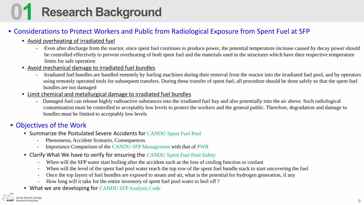
• Considerations to Protect Workers and Public from Radiological Exposure from Spent Fuel at SFP• Avoid overheating of irradiated fuel
- Even after discharge from the reactor, since spent fuel continues to produce power, the potential temperature increase caused by decay power should be controlled effectively to prevent overheating of both spent fuel and the materials used in the structures which have their respective temperature limits for safe operation
• Avoid mechanical damage to irradiated fuel bundles- Irradiated fuel bundles are handled remotely by fueling machines during their removal from the reactor into the irradiated fuel pool, and by operators
using remotely operated tools for subsequent transfers. During these transfer of spent fuel, all procedure should be done safely so that the spent fuel bundles are not damaged
• Limit chemical and metallurgical damage to irradiated fuel bundles- Damaged fuel can release highly radioactive substances into the irradiated fuel bay and also potentially into the air above. Such radiological
contamination must be controlled to acceptably low levels to protect the workers and the general public. Therefore, degradation and damage to bundles must be limited to acceptably low levels
• Objectives of the Work• Summarize the Postulated Severe Accidents for CANDU Spent Fuel Pool
- Phenomena, Accident Scenario, Consequences - Importance Comparison of the CANDU SFP Management with that of PWR
• Clarify What We have to verify for ensuring the CANDU Spent Fuel Pool Safety- When will the SFP water start boiling after the accident such as the loss of cooling function or coolant- When will the level of the spent fuel pool water reach the top row of the spent fuel bundle stack to start uncovering the fuel- Once the top layers of fuel bundles are exposed to steam and air, what is the potential for hydrogen generation, if any- How long will it take for the entire inventory of spent fuel pool water to boil off ?
• What we are developing for CANDU SFP Analysis Code


11
Canned Failed Fuel
• Refueling & Irradiated Fuel Transfer in CANDU• On-Power Refueling: average 2 channels (16 bundles) per day
- PROCEDURE• Loading 8 New fuel bundles into the Charge Machine (CM)• Locks both CM and Accept Machine (AM) on the pre-selected channel• Removing fuel channel hardware on both sides such as shield plug etc.• Loading new fuels from CM at the Reactor inlet & receiving spent fuels by AM at the Reactor outlet• Upon completion of fuel changing, AM goes to spent fuel port• Discharging spent fuels onto the spent fuel elevator through the spent fuel port• Lowers the spent fuels by elevator onto the conveyor belt of the spent fuel discharge room
(spent fuel discharge room is located inside the containment building, but not belong to a containment room)• Transporting of spent fuels form the discharge room in the reactor building to the reception bay• Transfer of spent fuel between buildings is under water through a containment gate
and a transfer canal, which connects the reception bay and spent fuel pool
Fueling Machine
New Fuel Storage Room
CONTAINMENT Building
New Fuel Loading Area
New Fuel Port
SERVICE Building
Charge Machine
REACTOR
Accept Machine
Spent Fuel Port
REACTOR Building
Spent FuelDischarge Room
Elevator
Failed FuelCanning
ContainmentGate
Transfer Canal
ReceptionBay
Spent Fuel Pool
Storage Tray
CONTAINMENT BuildingCanned Failed Fuel
12
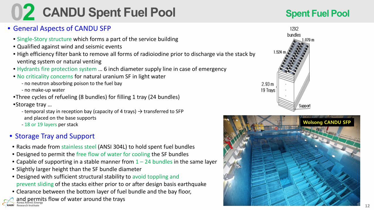
• General Aspects of CANDU SFP• Single-Story structure which forms a part of the service building• Qualified against wind and seismic events• High efficiency filter bank to remove all forms of radioiodine prior to discharge via the stack by
venting system or natural venting• Hydrants fire protection system … 6 inch diameter supply line in case of emergency• No criticality concerns for natural uranium SF in light water
- no neutron absorbing poison to the fuel bay - no make-up water
•Three cycles of refueling (8 bundles) for filling 1 tray (24 bundles)•Storage tray …
- temporal stay in reception bay (capacity of 4 trays) → transferred to SFP and placed on the base supports
- 18 or 19 layers per stack Wolsong CANDU SFP
• Storage Tray and Support• Racks made from stainless steel (ANSI 304L) to hold spent fuel bundles• Designed to permit the free flow of water for cooling the SF bundles• Capable of supporting in a stable manner from 1 – 24 bundles in the same layer• Slightly larger height than the SF bundle diameter• Designed with sufficient structural stability to avoid toppling and
prevent sliding of the stacks either prior to or after design basis earthquake• Clearance between the bottom layer of fuel bundle and the bay floor,
and permits flow of water around the trays

13
• Design Considerations for CANDU SFP to Ensure:• adequate cooling of the bundles in the pool,• avoidance of damage to bundles during their residence in the pool,• compliance with safeguards monitoring requirements (e.g., bundle serial numbers are readily visible),• direct transfer of bundles (basket only) into dry storage containers, and • use of the most compact arrangements of bundles in the pool
• CANDU SFP is Designed to …• accommodate spent fuels for 10 years (≈ 47,000 BDs) plus an additional full core discharge (4560 BDs)• have an inspection station where fuel can be inspected underwater• be filled with de-mineralized light water• have a dedicated purification and cooling system to keep the fuel covered with
de-mineralized water and cools and maintains water chemistry and activity at acceptable levels• prevent leakage by applying a glass fiber reinforced epoxy liner• have 1.22 m thick reinforced concrete base slab and side walls (double-wall) to satisfy
the shielding requirements and the stringent control on crack development because of possible temperature differentials across the wall thicknesses
• maintain water at a predetermined temperature and to continue to provide cooling to maintain at under 38 0C and at under 49 0C for the case of 10 year storage plus one full core load
• have dimension of 19.84m long, 11.89m wide and 9.77m deep• have water volume of 2,000 m3 and 700 m3 for reception bay • not covered by a leak-tight containment, so consequences of over-heating
and melting of fuel can be very severe

15
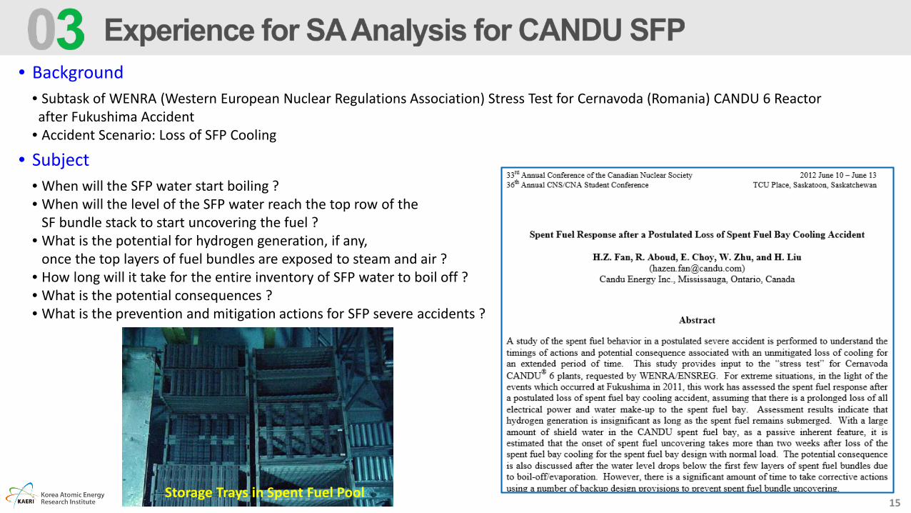
• Background• Subtask of WENRA (Western European Nuclear Regulations Association) Stress Test for Cernavoda (Romania) CANDU 6 Reactor after Fukushima Accident
• Accident Scenario: Loss of SFP Cooling
• Subject• When will the SFP water start boiling ?• When will the level of the SFP water reach the top row of the
SF bundle stack to start uncovering the fuel ?• What is the potential for hydrogen generation, if any,
once the top layers of fuel bundles are exposed to steam and air ?• How long will it take for the entire inventory of SFP water to boil off ?• What is the potential consequences ?• What is the prevention and mitigation actions for SFP severe accidents ?
Storage Trays in Spent Fuel Pool

16
• No make-up water is supplied to the SPP after the initiation of event conservatively minimize the available inventory for the SFP, and underestimate the time to SFB water boiling
• The minimum shield water volume used is based on the design requirement of the safety marker• Minimum shield water depth: 4.5 m ensures minimum immerse depth of 4.11 m at all times including a tray passing• Minimum shielding water volume: 1000 m3 covering all SF bundles
• Each tray layer is completed with SF bundles• 24 BDs per tray for all 112 tray stacks 2,688 BDs per tray layers (C1 for 19 layers 51,072 BDs, C2 for 18 layers 48,384 BDs)
• Designed normal heat load in the SFP is assumed • SFB normal heat load of 2 MW (designed value for SFB cooling system) conservative for determining the time to water boiling
• Limited heat removal mechanisms are considered• Only heat removal by bay water evaporation conservatively minimize the time to onset of boiling
These assumptions set up reasonable worse-case SFB conditions of less water inventory and more heat load to assess the SF response after a postulated loss of SFB cooling accident !

17
• Decay Power
• Range of BD power up to 800 kW at the nominal design power. • For normal CANDU 6 1/3 of fuel BD > 600 kW discharge power
& 80% of fuel BD > 300 kW• SFP heat load mainly comes from SF discharged in recent years
- about 50% within 1 year, about 80% within 3 years• Average bundle power for 2 MW ≒ 0.0426 kW (≒ 2 MW / 47,000 BD) • Accumulation rate of SF BD ≒ 90 BDs/week (usually 16 BDs per day)• Within a month, all fuel bundles’ powers are below 1.0 kW,
within 3 years of decay, all fuel bundles’ power are below 0.0426 kW• ∴ the assumption of 2 MW is quite conservative !
• Hydrogen Generation
• Sheath oxidation in steam (Zr/steam reaction)- Zr + 2H2O = ZrO2 +2H2 + Q … exothermic reaction
• Key temperature for Zr oxidation with steam- Onset temperature: 827 0C … oxidation starts - Transition temperature: 1577 0C- Fast reaction temperature: > 1850 0C
• Zr/steam reaction has a positive feedback on the fuel temperatureuntil all of the sheath material or steam is consumed
• Amount of Hydrogen Generation - Zirconium weight per bundle: 2.21 kg (2 kg for sheath and the rest for the endplates and appendages)
- Mole of Zirconium per bundle: 24.2 mole(∵ molecular weight of Zr = 91.22 g/mol )
- ∴ Each bundle has a potential to generate up to 48.5 mol of hydrogen (H2)

18
• Onset of SFP Water Boiling• Onset of the SFB water boiling: 60h 23min … 2.5 days• Shield water depth is maintained by the time onset of the boiling• No Zr/steam reaction is expected for sheath temperature lower
than 827 0C prior to SF bundle uncovering
Estimated Uncover Time for Top Layer
• Onset of SF Bundle Uncovering• Heat removal due to evaporation after onset of boiling is 2.26 MJ/kg(∵ enthalpies for water liquid and steam are 2.675 and 0.419 MJ/kg)
• Water to boil-off where the top row trays will start to get uncovered… additional 13.3 days based on evaporation enthalpy and heat load
• ∴ 15.8 days after the event initiation, sufficient pool water cooling will not be available for the top SF bundles
• Pool Water Boiling-off• Time to water boiled-off at the top layer: 7.36 hours from the onset of uncovering for the 2MW power and 18-trays stack• Time to boiled-off for top three layers: 23.5 hours water boiling-off slows down with more bundles uncovered • Time to uncover to low level layers with full power: 5.37 days• Time to uncover to low level layers with the decreasing power heating the remaining bay water and considering high ratio (1:2) of water to space in the SFB room and other environment cooling and condensation effects: long time in days

19
• Potential Consequence • From the above assessments … with a large amount of shield water in the CANDU SFP, as a passive inherent feature
- no cliff-edge effects are expected … 15.8 days until onset of spent fuel uncovering• If make-up continues to be unavailable with multi layers of SF uncovered over days or weeks … a potential for the consequence getting
worse (cliff-edge effects)- some parts of tray & tray supports would heat up and experience a loss of integrity … avobe 500 0C based on its material strength- onset of Zr-steam reaction with hydrogen generation
- some SF temperatures would increase substantially as there is less cooling available with the surrounding environment getting hot- possibility of the fuel sheath integrity failure significant fission product release from the failed fuel bundles
• Prevention & Mitigation Actions … restoring power or providing cooling water into SFP, preferably prior to SF uncovering
• Supply of make-up water to the SFP using the normal demineralized water• Back-up fire water system• Fire truck or mobile pump via 6-inch diameter supply line connections provided in the SFP design• If the SFP is still accessible, add water directly into the bay to maintain the water level• Collecting condensed water and back to the SFP
• CONCLUSIONS ! • Significant amount of time to take corrective actions to prevent uncovering of the SF bundles with the passive inherent feature • Onset of uncovering takes more than two weeks after a loss of the SFP cooling for the SFP design heat load • Hydrogen generation is insignificant as long as the spent fuel remains submerged• Potential worse consequence would be possible after the water level drops below the first few layers of SF bundles due to boil-off and
evaporation


21
• Pool drain … estimates the rate of drain of the spent fuel pool as a function of the postulated break size and location• Pool water evaporation … calculates water evaporation as a function of spent fuel pool water temperature profile and
building atmospheric conditions• Fuel bundle heat-up … estimates the heat-up of all uncovered fuel bundles following un-cover caused by drain• Air oxidation … air oxidation of Zr sheath can start first at bundles freshly removed from the reactor. This is more energetic
than steam oxidation and the exothermic heat can be transferred to adjacent bundles and initiate a runaway reaction that can propagate from one fuel tray to another. Hydrogen generated by air oxidation is coupled with hydrogen generation from others sources such as melt interaction with underlying water
• Fuel failure … various criteria models for fuel failure including onset of runaway oxidation as a failure trigger• Debris melt relocation … calculates the onset of melting of those fuel bundles whose average temperature exceeds
progressively the melting point of Zircaloy, eutectic or uranium• Melt quench and hydrogen generation … models quenching of melt and the steam and hydrogen production• Fission product release … estimates the FP release from the fuel bundles upon onset of deformation and upon melting• Fission product concentration in the building … calculates the concentration of FP in the SFP building and their release
into the environment upon room pressurization• SFP building behavior … calculates building response with special considerations to enhanced heat transfer to air and
structures in the upper part of the building• Mitigation actions• Fission product release into the environment … concentration of airborne FP in the SFP building is used along with the
building pressurization and leakage characteristics to evaluate the integrated discharge into the atmosphere

22
Operator actions to flood the pool with
firewaterPool drain calculations
Building pressurization and thermal response
Time of fuel uncovery
Fission product release into building
Fuel melting and relocation
Fuel heatup
Data for dose calculation
Fission product release into the
environment
Break discharge as a function of water level
Pump flow from recovery
Flow from pool to holdup tank
Heat removal by natural convection
and radiation
Decay heat
Steam production by quenching
Hydrogen production during quenching
Gas discharge to atmosphere
Building failure or rupture panel opening
Heat transfer to building structures
Heat loss to building atmosphere
Time of building isolation
Air Oxidation
Convective fire transfer
• Decay heat distribution in the fuel stacked in the pool basedon a specified history of fuel unloading from channels. Poolassumed full of its maximum inventory of fuel
• Evaporation from pool under forced convection cooling of theroom and under stagnant conditions if the ventilation systemis lost
• Draining of the pool due to evaporation, boiling and anaccidental drain hole
• Fuel bundle un-covery transients upon water drain• Air natural circulation potential within a stack (tower) in
various placement configurations (near free edge, near a wallor enclosed by other stacks)
• Thermal response of individual fuel bundles and storage trayswith underlying trays submerged
• Thermal response of individual fuel bundles and storage traysin air only
• Hydrogen production, transport and distribution• Fuel failure and relocation• Fission product release transients• Spent fuel bay room response• Effect and effectiveness of recovery actions

23
Module Phenomenon Detailed Calculation
POOL Model Pool Drain
∙ Break discharge calculation∙ Cooling system interactions∙ Evaporation due to forced and natural convecti
on∙ Water loss due to boiling∙ Bundle and rack uncover
FUEL Model
Decay Heat ∙ Decay curve for CANDU fuel
Fuel Heat-up∙ Heat transfer to fluids and structures∙ Interaction with underlying water∙ Steam and air oxidation
DEBRIS Model Fuel Melting & Relocation
∙ Debris interaction with air∙ Heat transfer and oxidation kinetics∙ Relocation of debris and melt∙ Steam and hydrogen production by interaction
of melt and debris with water
FISSION PRODUCT Model FP Release
∙ FP release into room∙ FP release from fuel and debris∙ FP deposition in pool
CONTAINMENT Model
Building Pressurization and Thermal Response
∙ Thermal and mechanical response of walls, roof structure
∙ Steam and hydrogen production by quenching∙ Pressure, temperature response of room air∙ Building failure or rupture
CONSEQUENCEModel
FP Release & Dose Calculation
∙ Debris-concrete interactions∙ Zirconium fires∙ Recovery modes∙ FP release into environment & dose calculation

24
• Summarized the current status of Spent Fuel Storage in Korea• Expansion of the Spent Fuel storage for CANDU is very URGENT ! • Present storage will be saturated by 2021 for CANDU spent fuels !
• Summarized the refueling process and spent fuel transfer for CANDU reactor• On-line refueling: 16 fuel bundles per everyday• Spent fuel transfer procedure from reactor to spent fuel pool• General aspects of CANDU spent fuel pool
• Experience of accident analysis for CANDU spent fuel pool • Deal with only a loss of cooling accident not a loss of coolant accident• Used a simple calculation method not by comprehensive analysis program
• Development status of SA analysis code for CANDU spent fuel pool• No analysis code exist for CANDU spent fuel pool accident considering the CANDU unique characteristics• Existing codes for LWR (MELCOR, MAAP5) are not applicable to CANDU spent fuel pool accident• Should consider the spent fuel layout in CANDU SFP, such as a horizontal dense storage of spent fuels on the fish basket which may
result in the Zircaloy fire and its easy propagation• We are now developing the analysis code for CANDU SFP accident based on the understanding of the major phenomena and preparing
the reasonable logic for analysis algorithm.

Thank you for your attention !


![[오픈콘텐츠랩] 꿈꾸는 프레젠테이션](https://img.pdfslide.net/doc/110x75/55a2fc6c1a28ab25748b4702/-55a2fc6c1a28ab25748b4702.jpg)