Embed Size (px)
Citation preview

MotionSolve와 OptiStruct를연계한피로해석프로세스
Fatigue Analysis Process using MotionSolve and OptiStruct
한국알테어
김주영
Contents
✓ Introduction
✓ Overall Process of Fatigue Analysis
✓ OptiStruct Flexible Body Generation
✓ MotionSolve Transient Run with Flex-body
✓ OptiStruct Transient & Fatigue Analysis
✓ Transient Fatigue Analysis Result (Stress, Damage)

Introduction
▪ Analytical Durability Evaluation
MBD FEA
FatiguePost

Introduction
Flexible body
preparation
MBD analysis
MBD model
definition
Fatigue analysis (Transient analysis)
Fatigue results
in HyperView
HyperView
.h3d
.mdl .xml
.mrf
.h3d
HyperMesh, OptiStruct
MotionView
MotionView, MotionSolve
OptiStruct
▪ MBD + Fatigue Analysis Process Overview
.h3d

Overall Process of Fatigue Analysis
“Subframe_recov.h3d” Flex-body is generated.
Open “motionSolve_full_model.mdl”
file in MotionView
Run “Fatigue_mbd.fem” filein OptiStruct
Generate CMS Flex-body of “Subframe” model
in OptiStruct (By running “Subframe.fem”)
• Fatigue Analysis in OptiStruct after Multibody Dynamic Analysis in MotionSolve.
• Solver Workflow : OptiStruct(*CMS)MotionSolve(Transient) OptiStruct(Fatigue)
“motionSolve_full_model.mrf” file is created.
Fatigue run Setting“Fatigue_mbd.fem” file
Setting & Transient Run “motionSolve_full_model.mdl” file in MotionSolve from within
MotionView
Check the Fatigue Damage and Stress results in HyperView
*CMS(Component Mode Synthesis): This method is a way to reduce the large finite element model to a small number of degree of freedom while keeping the virtual mass, stiffness and damping properties.

OptiStruct Flexible Body Generation (CMS Method)
• Generate CMS Flex-body of Subframe shell model in OptiStruct.(By running “Subframe.fem”)
• CMS Craig-Bampton(CB) method is used to generate Flex-body.
• ASET points are defined at the connection points to the rest of the multi-body car structure.(Interface or boundary degrees of freedom)
# CMS Setting :- Method *CB (Craig-Bampton)- Number of mode 15- Solver Lanzos
< OptiStruct Input file “Subframe.fem” >
ASET points
< Generated Flex-body “Subframe_recov.h3d” >

MotionSolve Transient Run with Flex-body
• The “motionsolve_full_model.mdl” file is opened in MotionView and generated Subframe Flex-body(“Subframe_recov.h3d”) is connected to interface points of MBD model.
• The model is then Run(Type : Transient) from within MotionView as follows.
• This creates the “motionsolve_full_model.mrf” file with modal participation factors which are required for subsequent Transient Fatigue in OptiStruct.
< Subframe CMS Flex-body with MBD model >
< 4-Post Transient Run >

OptiStruct Transient & Fatigue Analysis (Run setting)
• After running MotionSolve, an *.mrf file is created which contains the MotionSolve resultsincluding modal participation factors at each time step for the Flex-body for transient analysis.
• In the Residual Run, the Flex-body “Subframe_recov.h3d” file and the“motionsolve_full_model.mrf” file are referenced using ASSIGN command.
• Use ASSIGN,H3DMBD,10504,Subframe_recov.h3d (here the ID 10504 represents the Flex-body ID; in the “motionsolve_full_model.mrf” file, as seen below in HyperGraph).
• Use ASSIGN,MBDINP,1,motionsolve_full_model.mrf (here the ID 1 represents the subcase ID of a dummy transient subcase in the residual run *.fem file, as seen below).
< HyperGraph : Finding Flex-body ID >
< OptiStruct Input file “Fatigue_mbd.fem” >
Dummy Transient Subcase
Fatigue Subcase

• Dummy loading and via TLOAD1 entry should be specified.
• Note that loading should be applied via SPCD only on the TLOAD1 entry.
• Loading defined here is NOT used in the OptiStruct Transient run.
• Instead, the modal participation factors from the *.mrf file is used to recover the transient stresses for further fatigue analysis.
• Number of timesteps in dummy TSTEP should match with number of timesteps of the initial MotionSolve Transient run.
OptiStruct Transient & Fatigue Analysis (Run setting)
Only SPCD Loading
Timesteps should match with MotionSolve run
Type of excitation: Displacement

• Fatigue run requires assigning properties to the elements in the Flex-body.
• “EL2PROP” entry is used to assign PSHELL property to all elements in the Flex-body.
• This property is then used to define the elements on FATDEF for consideration inFatigue analysis.
EL2PROP’s ID
Element Set ID Property ID
OptiStruct Transient & Fatigue Analysis (Run setting)

• The FATLOAD entry LCID(Loadcase ID) field should point to the dummy transient subcase.
• The N# field of the FATSEQ continuation line should be set equal to the number of times this Transient event is expected to occur for the model.
• 5,000cycles of 10 second Transient Event each is considered in the Fatigue analysis.
Number of repeats of FATEVNT 501
Transient Subcase ID
OptiStruct Transient & Fatigue Analysis (Run setting)

• Fatigue Analysis performed is Uniaxial Transient Fatigue Analysis.
• Uses Strain-Life Approach (EN) which requires input of Strain-Life curve as part ofmaterial data.
• We use Typical data for Steel, for both material information on MAT1 card and Fatigue data on the MATFAT card. MATFAT data is as follows for analysis model.
*Strain-Life (EN) approach shouldbe used for low cycle fatigue where plastic strains are key contributorsfor fatigue damage.
E-N Fatigue properties : YS, UTS, sf’, b, c, ef’ N’, K’, NC
E-N Fatigue parameters define
OptiStruct Transient & Fatigue Analysis (Run setting)

Transient Analysis Result
• The following stress result can be reviewed from 10 seconds transient run.
< Transient Stress Plot >
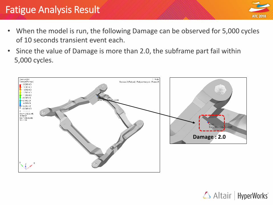
Fatigue Analysis Result
• When the model is run, the following Damage can be observed for 5,000 cycles of 10 seconds transient event each.
• Since the value of Damage is more than 2.0, the subframe part fail within5,000 cycles.
Damage : 2.0

Thank You!!